US7556679B2 - Processes for preparing phase change inks - Google Patents
Processes for preparing phase change inks Download PDFInfo
- Publication number
- US7556679B2 US7556679B2 US11/197,600 US19760005A US7556679B2 US 7556679 B2 US7556679 B2 US 7556679B2 US 19760005 A US19760005 A US 19760005A US 7556679 B2 US7556679 B2 US 7556679B2
- Authority
- US
- United States
- Prior art keywords
- mixing chamber
- dispersion
- ink
- phase change
- coloring material
- Prior art date
- Legal status (The legal status is an assumption and is not a legal conclusion. Google has not performed a legal analysis and makes no representation as to the accuracy of the status listed.)
- Active, expires
Links
- 230000008859 change Effects 0.000 title claims abstract description 49
- 238000000034 method Methods 0.000 title claims abstract description 34
- 230000008569 process Effects 0.000 title claims abstract description 26
- 239000000976 ink Substances 0.000 title description 150
- 239000000049 pigment Substances 0.000 claims abstract description 24
- 239000000203 mixture Substances 0.000 claims description 49
- 238000002156 mixing Methods 0.000 claims description 42
- 239000000463 material Substances 0.000 claims description 40
- 239000006185 dispersion Substances 0.000 claims description 32
- 238000004040 coloring Methods 0.000 claims description 23
- 239000002245 particle Substances 0.000 claims description 20
- 239000003795 chemical substances by application Substances 0.000 claims description 17
- 238000012360 testing method Methods 0.000 claims description 15
- 238000001914 filtration Methods 0.000 claims description 13
- 239000000654 additive Substances 0.000 claims description 10
- 239000003365 glass fiber Substances 0.000 claims description 6
- 239000004094 surface-active agent Substances 0.000 claims description 6
- 238000004891 communication Methods 0.000 claims description 5
- 238000004519 manufacturing process Methods 0.000 claims description 5
- 229920000642 polymer Polymers 0.000 claims description 5
- 238000012545 processing Methods 0.000 claims description 4
- 150000003839 salts Chemical class 0.000 claims description 4
- 150000001412 amines Chemical class 0.000 claims description 3
- 239000012528 membrane Substances 0.000 claims description 3
- 239000002184 metal Substances 0.000 claims description 3
- 229920006318 anionic polymer Polymers 0.000 claims description 2
- 229920006317 cationic polymer Polymers 0.000 claims description 2
- 238000001125 extrusion Methods 0.000 claims description 2
- 150000003242 quaternary ammonium salts Chemical class 0.000 claims description 2
- 230000000996 additive effect Effects 0.000 claims 4
- 239000007787 solid Substances 0.000 abstract description 21
- 238000002360 preparation method Methods 0.000 abstract description 6
- 239000012071 phase Substances 0.000 description 43
- 239000000975 dye Substances 0.000 description 17
- 239000007788 liquid Substances 0.000 description 14
- 239000000758 substrate Substances 0.000 description 14
- 239000000047 product Substances 0.000 description 13
- 239000003086 colorant Substances 0.000 description 12
- 150000001875 compounds Chemical class 0.000 description 11
- 239000001993 wax Substances 0.000 description 10
- 229920005989 resin Polymers 0.000 description 9
- 239000011347 resin Substances 0.000 description 9
- 238000012546 transfer Methods 0.000 description 8
- 238000007639 printing Methods 0.000 description 7
- 238000009826 distribution Methods 0.000 description 6
- 239000006229 carbon black Substances 0.000 description 5
- -1 polyethylene Polymers 0.000 description 5
- RSWGJHLUYNHPMX-UHFFFAOYSA-N Abietic-Saeure Natural products C12CCC(C(C)C)=CC2=CCC2C1(C)CCCC2(C)C(O)=O RSWGJHLUYNHPMX-UHFFFAOYSA-N 0.000 description 4
- OKTJSMMVPCPJKN-UHFFFAOYSA-N Carbon Chemical group [C] OKTJSMMVPCPJKN-UHFFFAOYSA-N 0.000 description 4
- KHPCPRHQVVSZAH-HUOMCSJISA-N Rosin Natural products O(C/C=C/c1ccccc1)[C@H]1[C@H](O)[C@@H](O)[C@@H](O)[C@@H](CO)O1 KHPCPRHQVVSZAH-HUOMCSJISA-N 0.000 description 4
- 125000000217 alkyl group Chemical group 0.000 description 4
- 125000003118 aryl group Chemical group 0.000 description 4
- 239000011248 coating agent Substances 0.000 description 4
- 238000000576 coating method Methods 0.000 description 4
- 239000004615 ingredient Substances 0.000 description 4
- 238000002844 melting Methods 0.000 description 4
- 230000008018 melting Effects 0.000 description 4
- 239000000126 substance Substances 0.000 description 4
- KZNICNPSHKQLFF-UHFFFAOYSA-N succinimide Chemical compound O=C1CCC(=O)N1 KZNICNPSHKQLFF-UHFFFAOYSA-N 0.000 description 4
- 229920002803 thermoplastic polyurethane Polymers 0.000 description 4
- KHPCPRHQVVSZAH-UHFFFAOYSA-N trans-cinnamyl beta-D-glucopyranoside Natural products OC1C(O)C(O)C(CO)OC1OCC=CC1=CC=CC=C1 KHPCPRHQVVSZAH-UHFFFAOYSA-N 0.000 description 4
- JOYRKODLDBILNP-UHFFFAOYSA-N Ethyl urethane Chemical compound CCOC(N)=O JOYRKODLDBILNP-UHFFFAOYSA-N 0.000 description 3
- 239000002270 dispersing agent Substances 0.000 description 3
- 150000002148 esters Chemical class 0.000 description 3
- 238000009472 formulation Methods 0.000 description 3
- 238000000265 homogenisation Methods 0.000 description 3
- 239000012943 hotmelt Substances 0.000 description 3
- 239000012948 isocyanate Substances 0.000 description 3
- 150000002513 isocyanates Chemical class 0.000 description 3
- 239000007791 liquid phase Substances 0.000 description 3
- 230000007774 longterm Effects 0.000 description 3
- 238000003860 storage Methods 0.000 description 3
- 239000004698 Polyethylene Substances 0.000 description 2
- 229920001807 Urea-formaldehyde Polymers 0.000 description 2
- PFEOZHBOMNWTJB-UHFFFAOYSA-N [H]C([H])(C)C([H])(C)CC Chemical compound [H]C([H])(C)C([H])(C)CC PFEOZHBOMNWTJB-UHFFFAOYSA-N 0.000 description 2
- LLCMFPYYLILXFI-UHFFFAOYSA-N [H]C([H])(C)C([H])(C)OCC[CH2] Chemical compound [H]C([H])(C)C([H])(C)OCC[CH2] LLCMFPYYLILXFI-UHFFFAOYSA-N 0.000 description 2
- 239000002253 acid Substances 0.000 description 2
- 239000003963 antioxidant agent Substances 0.000 description 2
- 230000015572 biosynthetic process Effects 0.000 description 2
- 239000004202 carbamide Substances 0.000 description 2
- 229910052799 carbon Inorganic materials 0.000 description 2
- 235000014113 dietary fatty acids Nutrition 0.000 description 2
- 238000001035 drying Methods 0.000 description 2
- 239000000194 fatty acid Substances 0.000 description 2
- 229930195729 fatty acid Natural products 0.000 description 2
- 150000004665 fatty acids Chemical class 0.000 description 2
- 150000002193 fatty amides Chemical class 0.000 description 2
- 239000010408 film Substances 0.000 description 2
- 239000012467 final product Substances 0.000 description 2
- 238000007641 inkjet printing Methods 0.000 description 2
- 239000012038 nucleophile Substances 0.000 description 2
- LYRFLYHAGKPMFH-UHFFFAOYSA-N octadecanamide Chemical compound CCCCCCCCCCCCCCCCCC(N)=O LYRFLYHAGKPMFH-UHFFFAOYSA-N 0.000 description 2
- 239000000123 paper Substances 0.000 description 2
- 229920000573 polyethylene Polymers 0.000 description 2
- 229920001343 polytetrafluoroethylene Polymers 0.000 description 2
- 239000004810 polytetrafluoroethylene Substances 0.000 description 2
- 239000000843 powder Substances 0.000 description 2
- 238000003908 quality control method Methods 0.000 description 2
- 239000002994 raw material Substances 0.000 description 2
- 239000000376 reactant Substances 0.000 description 2
- 239000007790 solid phase Substances 0.000 description 2
- 239000003381 stabilizer Substances 0.000 description 2
- 125000001424 substituent group Chemical group 0.000 description 2
- 229960002317 succinimide Drugs 0.000 description 2
- 238000010998 test method Methods 0.000 description 2
- 239000010409 thin film Substances 0.000 description 2
- 239000012745 toughening agent Substances 0.000 description 2
- 150000003626 triacylglycerols Chemical class 0.000 description 2
- 239000004034 viscosity adjusting agent Substances 0.000 description 2
- IIZPXYDJLKNOIY-JXPKJXOSSA-N 1-palmitoyl-2-arachidonoyl-sn-glycero-3-phosphocholine Chemical compound CCCCCCCCCCCCCCCC(=O)OC[C@H](COP([O-])(=O)OCC[N+](C)(C)C)OC(=O)CCC\C=C/C\C=C/C\C=C/C\C=C/CCCCC IIZPXYDJLKNOIY-JXPKJXOSSA-N 0.000 description 1
- 239000004215 Carbon black (E152) Substances 0.000 description 1
- 229920002302 Nylon 6,6 Polymers 0.000 description 1
- ULUAUXLGCMPNKK-UHFFFAOYSA-N Sulfobutanedioic acid Chemical compound OC(=O)CC(C(O)=O)S(O)(=O)=O ULUAUXLGCMPNKK-UHFFFAOYSA-N 0.000 description 1
- XSQUKJJJFZCRTK-UHFFFAOYSA-N Urea Chemical compound NC(N)=O XSQUKJJJFZCRTK-UHFFFAOYSA-N 0.000 description 1
- 0 [1*]C(=O)CC(=O)[3*]C(=O)CC([5*])=O Chemical compound [1*]C(=O)CC(=O)[3*]C(=O)CC([5*])=O 0.000 description 1
- 239000000980 acid dye Substances 0.000 description 1
- 150000001252 acrylic acid derivatives Chemical class 0.000 description 1
- NIXOWILDQLNWCW-UHFFFAOYSA-N acrylic acid group Chemical group C(C=C)(=O)O NIXOWILDQLNWCW-UHFFFAOYSA-N 0.000 description 1
- 238000005054 agglomeration Methods 0.000 description 1
- 230000002776 aggregation Effects 0.000 description 1
- 230000032683 aging Effects 0.000 description 1
- 150000001298 alcohols Chemical class 0.000 description 1
- 239000007864 aqueous solution Substances 0.000 description 1
- 239000000981 basic dye Substances 0.000 description 1
- 238000010923 batch production Methods 0.000 description 1
- 230000008901 benefit Effects 0.000 description 1
- 230000000740 bleeding effect Effects 0.000 description 1
- 239000012876 carrier material Substances 0.000 description 1
- 238000012512 characterization method Methods 0.000 description 1
- 239000002131 composite material Substances 0.000 description 1
- 238000010276 construction Methods 0.000 description 1
- 229920001577 copolymer Polymers 0.000 description 1
- 238000005336 cracking Methods 0.000 description 1
- 238000013461 design Methods 0.000 description 1
- 238000011161 development Methods 0.000 description 1
- 230000018109 developmental process Effects 0.000 description 1
- 238000010586 diagram Methods 0.000 description 1
- VJHINFRRDQUWOJ-UHFFFAOYSA-N dioctyl sebacate Chemical compound CCCCC(CC)COC(=O)CCCCCCCCC(=O)OCC(CC)CCCC VJHINFRRDQUWOJ-UHFFFAOYSA-N 0.000 description 1
- 239000000982 direct dye Substances 0.000 description 1
- 239000000986 disperse dye Substances 0.000 description 1
- 230000000694 effects Effects 0.000 description 1
- 238000005516 engineering process Methods 0.000 description 1
- 238000001704 evaporation Methods 0.000 description 1
- 230000008020 evaporation Effects 0.000 description 1
- 239000004744 fabric Substances 0.000 description 1
- 238000007646 gravure printing Methods 0.000 description 1
- 239000008240 homogeneous mixture Substances 0.000 description 1
- 229930195733 hydrocarbon Natural products 0.000 description 1
- 150000002430 hydrocarbons Chemical class 0.000 description 1
- 238000002372 labelling Methods 0.000 description 1
- 239000000787 lecithin Substances 0.000 description 1
- 229940067606 lecithin Drugs 0.000 description 1
- 235000010445 lecithin Nutrition 0.000 description 1
- 239000012803 melt mixture Substances 0.000 description 1
- 150000002734 metacrylic acid derivatives Chemical class 0.000 description 1
- 125000001570 methylene group Chemical group [H]C([H])([*:1])[*:2] 0.000 description 1
- 239000004200 microcrystalline wax Substances 0.000 description 1
- 235000019808 microcrystalline wax Nutrition 0.000 description 1
- 230000005012 migration Effects 0.000 description 1
- 238000013508 migration Methods 0.000 description 1
- 238000012986 modification Methods 0.000 description 1
- 230000004048 modification Effects 0.000 description 1
- 150000002903 organophosphorus compounds Chemical class 0.000 description 1
- 230000035515 penetration Effects 0.000 description 1
- 230000000737 periodic effect Effects 0.000 description 1
- 239000003208 petroleum Substances 0.000 description 1
- 229920000058 polyacrylate Polymers 0.000 description 1
- 239000011148 porous material Substances 0.000 description 1
- 238000004886 process control Methods 0.000 description 1
- 238000005086 pumping Methods 0.000 description 1
- 239000012260 resinous material Substances 0.000 description 1
- 230000004044 response Effects 0.000 description 1
- 229920006395 saturated elastomer Polymers 0.000 description 1
- 239000000344 soap Substances 0.000 description 1
- 239000002904 solvent Substances 0.000 description 1
- 239000000992 solvent dye Substances 0.000 description 1
- 229940124530 sulfonamide Drugs 0.000 description 1
- 150000003456 sulfonamides Chemical class 0.000 description 1
- 150000003871 sulfonates Chemical class 0.000 description 1
- 229920003002 synthetic resin Polymers 0.000 description 1
- 239000000057 synthetic resin Substances 0.000 description 1
- 239000003784 tall oil Substances 0.000 description 1
- 238000002411 thermogravimetry Methods 0.000 description 1
- 229920001169 thermoplastic Polymers 0.000 description 1
- 239000004416 thermosoftening plastic Substances 0.000 description 1
- 239000003981 vehicle Substances 0.000 description 1
- 125000000391 vinyl group Chemical group [H]C([*])=C([H])[H] 0.000 description 1
- 229920002554 vinyl polymer Polymers 0.000 description 1
- 238000005303 weighing Methods 0.000 description 1
Images


Classifications
-
- B—PERFORMING OPERATIONS; TRANSPORTING
- B41—PRINTING; LINING MACHINES; TYPEWRITERS; STAMPS
- B41J—TYPEWRITERS; SELECTIVE PRINTING MECHANISMS, i.e. MECHANISMS PRINTING OTHERWISE THAN FROM A FORME; CORRECTION OF TYPOGRAPHICAL ERRORS
- B41J2/00—Typewriters or selective printing mechanisms characterised by the printing or marking process for which they are designed
- B41J2/005—Typewriters or selective printing mechanisms characterised by the printing or marking process for which they are designed characterised by bringing liquid or particles selectively into contact with a printing material
- B41J2/01—Ink jet
- B41J2/17—Ink jet characterised by ink handling
- B41J2/175—Ink supply systems ; Circuit parts therefor
- B41J2/17593—Supplying ink in a solid state
-
- B—PERFORMING OPERATIONS; TRANSPORTING
- B01—PHYSICAL OR CHEMICAL PROCESSES OR APPARATUS IN GENERAL
- B01F—MIXING, e.g. DISSOLVING, EMULSIFYING OR DISPERSING
- B01F27/00—Mixers with rotary stirring devices in fixed receptacles; Kneaders
- B01F27/27—Mixers with stator-rotor systems, e.g. with intermeshing teeth or cylinders or having orifices
- B01F27/271—Mixers with stator-rotor systems, e.g. with intermeshing teeth or cylinders or having orifices with means for moving the materials to be mixed radially between the surfaces of the rotor and the stator
- B01F27/2711—Mixers with stator-rotor systems, e.g. with intermeshing teeth or cylinders or having orifices with means for moving the materials to be mixed radially between the surfaces of the rotor and the stator provided with intermeshing elements
-
- B—PERFORMING OPERATIONS; TRANSPORTING
- B01—PHYSICAL OR CHEMICAL PROCESSES OR APPARATUS IN GENERAL
- B01F—MIXING, e.g. DISSOLVING, EMULSIFYING OR DISPERSING
- B01F33/00—Other mixers; Mixing plants; Combinations of mixers
- B01F33/80—Mixing plants; Combinations of mixers
- B01F33/81—Combinations of similar mixers, e.g. with rotary stirring devices in two or more receptacles
- B01F33/811—Combinations of similar mixers, e.g. with rotary stirring devices in two or more receptacles in two or more consecutive, i.e. successive, mixing receptacles or being consecutively arranged
-
- B—PERFORMING OPERATIONS; TRANSPORTING
- B41—PRINTING; LINING MACHINES; TYPEWRITERS; STAMPS
- B41J—TYPEWRITERS; SELECTIVE PRINTING MECHANISMS, i.e. MECHANISMS PRINTING OTHERWISE THAN FROM A FORME; CORRECTION OF TYPOGRAPHICAL ERRORS
- B41J2/00—Typewriters or selective printing mechanisms characterised by the printing or marking process for which they are designed
- B41J2/005—Typewriters or selective printing mechanisms characterised by the printing or marking process for which they are designed characterised by bringing liquid or particles selectively into contact with a printing material
- B41J2/01—Ink jet
- B41J2/17—Ink jet characterised by ink handling
- B41J2/175—Ink supply systems ; Circuit parts therefor
Definitions
- the presently disclosed embodiments are directed to processes for making phase change or solid ink used in ink jet system recording apparatuses (e.g., printer, copying machine, facsimile, word processor, plotter, and the like). More particularly, the embodiments pertain to the preparation of pigment or dye-based solid inks using a high shear in-line homogenizer with a rotor-stator style blade for improved dispersion.
- the in-line homogenizer uses multiple stages tooling and is installed outside of the vessel so that the homogenizers are not limited to specific mixing chamber geometries or vessel geometries.
- Recording apparatuses using an ink jet system employ a recording method in which a liquid or fused solid ink is ejected as small droplets through a nozzle, slit, porous film, or the like, and deposited onto the surface of a recording material such as paper, cloth, or film to record letters or figures on the recording material.
- a recording material such as paper, cloth, or film to record letters or figures on the recording material.
- An ink for use in an ink jet recording apparatus mainly comprises a liquid, a coloring material and additives.
- Such ink is generally required to have properties including: the formation of a record having high-resolution and high-density uniform image without causing blotting or fogging on the recording material, the ability to be used without clogging nozzle tips due to drying of the ink, the facilitation of ejection responsibility and stability so that the nozzle tip is kept in good condition, the exhibition of good drying property, the formation of an image with good fastness, and the high stability to ensure long-term storage.
- Additives that may be added to the dispersed coloring material and the liquid include a surfactant or a fixing agent.
- a surfactant may added to lower the surface tension of the liquid to obtain acceptable levels of transfer, coating spread and adhesion.
- a fixing agent may be added to prevent permeation of the coloring material in the ink.
- Other additives may also be included in the ink, such as antioxidants, viscosity modifiers, clarifiers, conductivity agents and dyes used as auxiliary colorants, as disclosed in U.S. Pat. No. 6,878,198 and U.S. Patent Publication No. 20050113482, the disclosures of each of which are totally incorporated herein by reference.
- Factors such as droplet and particle size may have effect on whether the ink formed will have the desired properties.
- Pigment solids should be small and evenly dispersed to ensure that the droplets will be small and uniformly emulsified.
- Providing uniformly dispersed pigments in small droplets may result in higher particle surface area, and thus, more brilliant color and smoother finish.
- Providing smaller particle and droplet size may also further facilitate better penetration into the recording material so that the image created dries better, is more resistant to rubbing or bleeding and may impart higher stability for long-term storage.
- the quality of the product ink may be controlled by “Filter Tests,” e.g., a ink-making process is satisfactory if the product ink passes such a “Filter Test.”
- the finished ink is evaluated by a number of characterization tests including viscosity, thermo-gravimetric analyses, various filtration tests and print quality tests.
- the filtration tests were designed to emulate flow of molten ink through a printer head. For example, one of the filtration tests conducted involves measuring 100 grams of molten ink at fixed temperature (105-135° C.) and pressure (15 psig) as the ink passes through a 0.45 ⁇ m glass fiber membrane per unit time. An ink which meets the specification will pass through the 0.45 ⁇ m filter membrane in less than 5 minutes. Inks which are not homogenized adequately or filtered properly will not pass through under 5 minutes.
- phase change inks are desirable for ink jet printers because they remain in a solid phase at room temperature during shipping, long term storage, and the like.
- the problems associated with nozzle clogging as a result of ink evaporation with liquid ink jet inks are largely eliminated, thereby improving the reliability of the ink jet printing.
- the ink droplets are applied directly onto the final recording substrate (for example, paper, transparency material, and the like), the droplets solidify immediately upon contact with the substrate, so that migration of ink along the printing medium is prevented and dot quality is improved.
- phase change or solid inks are in the solid phase at ambient temperature, but exist in the liquid phase at the elevated operating temperature of an ink jet printing device. At the jet operating temperature, droplets of liquid ink are ejected from the printing device and, when the ink droplets contact the surface of the recording substrate, either directly or via an intermediate heated transfer belt or drum, they quickly solidify to form a predetermined pattern of solidified ink drops.
- Phase change inks have been used in other printing technologies, such as gravure printing, as disclosed in, for example, U.S. Pat. No. 5,496,879 and German Patent Publications DE 4205636AL and DE 4205713AL, the disclosures of each of which are totally incorporated herein by reference. Phase change inks have also been used for applications such as postal marking and industrial marking and labeling.
- Phase change inks for color printing typically comprise a phase change ink carrier composition which is combined with a phase change ink compatible pigment colorant.
- a series of colored phase change inks can be formed by combining ink carrier compositions with compatible subtractive primary colorants.
- the subtractive primary colored phase change inks can comprise four component dyes, namely, cyan, magenta, yellow and black, although the inks are not limited to these four colors.
- These subtractive primary colored inks can be formed by using a single dye or a mixture of dyes.
- magenta can be obtained by using a mixture of Solvent Red Dyes or a composite black can be obtained by mixing several dyes.
- the subtractive primary colorants employed can comprise dyes from the classes of Color Index (C.I.) Solvent Dyes, Disperse Dyes, modified Acid and Direct Dyes, and Basic Dyes.
- the colorants can also include pigments, as disclosed in, for example, U.S. Pat. No. 5,221,335, the disclosure of which is totally incorporated herein by reference.
- U.S. Pat. No. 5,621,022 the disclosure of which is totally incorporated herein by reference, discloses the use of a specific class of polymeric dyes in phase change ink compositions.
- compositions suitable for use as phase change ink carrier compositions are known.
- Some representative examples of references disclosing such materials include U.S. Pat. No. 3,653,932, U.S. Pat. No. 4,390,369, U.S. Pat. No. 4,484,948, U.S. Pat. No. 4,684,956, U.S. Pat. No. 4,851,045, U.S. Pat. No. 4,889,560, U.S. Pat. No. 5,006,170, U.S. Pat. No. 5,151,120, U.S. Pat. No. 5,372,852, U.S. Pat. No.
- Suitable carrier materials can include paraffins, microcrystalline waxes, polyethylene waxes, ester waxes, fatty acids and other waxy materials, fatty amide containing materials, sulfonamide materials, resinous materials made from different natural sources (tall oil rosins and rosin esters, for example), and many synthetic resins, oligomers, polymers, and copolymers.
- U.S. Pat. No. 4,889,560 discloses a phase change ink carrier composition combined with a compatible colorant to form a phase change ink composition.
- a thin film of substantially uniform thickness of that phase change ink carrier composition, and the ink produced therefrom, has a high degree of lightness and chroma.
- the thin films of a substantially uniform thickness of the ink composition are also rectilinearly light transmissive.
- the carrier composition is preferably a fatty amide-containing compound.
- U.S. Pat. No. 4,889,761 discloses a method for producing a light-transmissive phase change ink printed substrate is described which comprises providing a substrate, and then printing on at least one surface of the substrate a predetermined pattern of a light-transmissive phase change ink which initially transmits light in a non-rectilinear path.
- the pattern of solidified phase change ink is then reoriented to form an ink layer of substantially uniform thickness. This ink layer will, in turn, produce an image which then will transmit light in a substantially rectilinear path.
- the substrate is light transmissive, and the reoriented printed substrate exhibits a high degree of lightness and chroma, and transmits light in a substantially rectilinear path.
- the reoriented printed substrate can be used in a projection device to project an image containing clear, saturated colors.
- phase change ink composition that is indirectly applied to a substrate by raising the temperature of the phase change ink composition to form a liquid phase change ink composition, applying droplets of the phase change ink composition in a liquid phase to a liquid intermediate transfer surface on a solid support in a pattern using a device such as an ink jet print head, solidifying the phase change ink composition on the liquid intermediate transfer surface, transferring the phase change ink composition from the liquid intermediate transfer surface to the substrate, and fixing the phase change ink composition to the substrate.
- the phase change ink composition is malleable when the ink is transferred from the intermediate transfer surface to the substrate and is ductile after the ink has been transferred to the substrate and cooled to ambient temperature to preclude the ink from crumbling and cracking.
- U.S. Pat. No. 5,782,966 (Bui et al.), the disclosure of which is totally incorporated herein by reference, discloses resins and waxes made by reacting selected nucleophiles, including alcohols and/or amines, with an isocyanate.
- the order of addition of the isocyanate and the different nucleophiles can tailor the distribution of di-urethane, mixed urethane/urea, and/or di-urea molecules in the final resin product.
- the isocyanate-derived resin and wax materials are useful as ingredients as phase change ink carrier compositions used to make phase change ink jet inks.
- phase change carrier compositions made from the combination of at least one urethane resin; at least one urethane/urea resin; at least one mono-amide; and at least one polyethylene wax.
- the order of addition of the reactants to form the reactant product urethane resin and urethane/urea resin permits the tailoring or design engineering of desired properties.
- X.sub.1, X.sub.2, X.sub.3, and X.sub.4 are segments comprising atoms selected from groups V and VI of the periodic table; wherein at least one R.sub.1 and R.sub.5 comprises at least 37 carbon units; and wherein R.sub.2, R.sub.3, and R.sub.4 each comprise at least one carbon unit.
- the invention further encompasses a composition of matter, as well as methods of reducing coefficients of friction of phase change ink formulations.
- U.S. Pat. No. 6,309,453 (Banning et al.), the disclosure of which is totally incorporated herein by reference, discloses colorless compounds having a central core and at least two arms extending from the core.
- the core can comprise one or more atoms.
- the at least two arms have the
- Z is a segment of one or more atoms; j is an integer from 1 to about 300 and can be different at one of the at least two arms than at another of the at least two arms; Q is an alkyl or aryl group and can vary amongst different alkyl and aryl groups within the colorless compound; and n is an integer greater than 1 and can be different at one of the at least two arms than at another of the at least two arms.
- the invention encompasses phase change inks incorporating the above-described colorless compound as toughening agent, and methods of printing with such phase change inks.
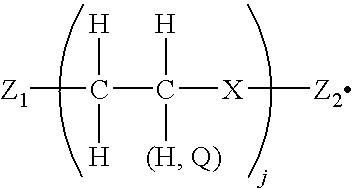
- the invention further includes a solid ink comprising a colorant and a colorless compound of the
- X is a single atom corresponding to N or O;
- Z.sub.1 and Z.sub.2 are substituents comprising one or more atoms, and can be the same as one another or different from one another; and
- j is an integer from 1 to about 50.
- U.S. Pat. No. 6,380,423 (Banning et al.), the disclosure of which is totally incorporated herein by reference, discloses colorless compounds having a central core and at least two arms extending from the core.
- the core can comprise one or more atoms.
- the at least two arms have the
- Z is a segment of one or more atoms; j is an integer from 1 to about 300 and can be different at one of the at least two arms than at another of the at least two arms; Q is an alkyl or aryl group and can vary amongst different alkyl and aryl groups within the colorless compound; and n is an integer greater than 1 and can be different at one of the at least two arms than at another of the at least two arms.
- the invention encompasses phase change inks incorporating the above-described colorless compound as toughening agent, and methods of printing with such phase change inks.
- the invention further includes a solid ink comprising a colorant and a colorless compound of the
- X is a single atom corresponding to N or O;
- Z.sub.1 and Z.sub.2 are substituents comprising one or more atoms, and can be the same as one another or different from one another; and
- j is an integer from 1 to about 50.
- U.S. Pat. No. 5,221,335 discloses a stabilized pigmented hot melt ink containing a thermoplastic vehicle, a coloring pigment, and a dispersion-stabilizing agent to inhibit settling or agglomeration of the pigment when the ink is molten, comprising 1.5 to 20 weight percent of a nitrogen-modified acrylate polymer.
- a preferred dispersion-stabilizing agent is the nitrogen-modified methacrylate polymer marketed by Rohm & Haas Co. as Plexol 1525.
- U.S. Pat. No. 5,800,600 (Lima-Marquez et al.), the disclosure of which is totally incorporated herein by reference, discloses a solid ink jet ink composition which is suitable for hot melt applications having a carrier having an electrical resistivity of at least 10.sup.8 Ohm ⁇ cm, insoluble marking particles, and a particle charging agent dispersed in it.
- the marking particle may be a pigment, an insoluble dyestuff, a polymer, or mixture thereof.
- the particle charging agent may be a metal soap, a fatty acid, lecithin, an organic phosphorous compound, a succinimide, a sulfosuccinate, petroleum sulfonates, a soluble or partially soluble resin such as a modified rosin ester, an acrylic, a vinyl, a hydrocarbon, or a mixture thereof.
- the solid ink jet ink composition may further include a viscosity controller.
- the ink may be capable of being heated to 155.degree. C. and have at that temperature a viscosity of between 5 to 150 centipoise.
- U.S. Pat. No. 6,858,070 discloses the use of single high shear mixers to manufacture ink, the entire disclosure thereof being incorporated herein by reference.
- Dye-based solid inks are commonly manufactured by dispersing the dyes and other ink components into molten wax in mixing chambers, such as feed tanks, using batch mixers with saw-tooth style or other single-stage “in-tank” impellers. Although saw-tooth style and other single-stage high speed in-tank batch mixers are adequate for dispersion of dyes in molten wax, they do not provide the adequate shear rate necessary for breaking up pigment agglomerates to submicron sized particles.
- ink jet inks involves homogenizers that have rotor-stator style in-tank batch mixers.
- This batch process has been developed for preparing pigment-based solid ink by dispersing the pigments and other ingredients into molten wax in a type of mixing chamber using a rotor-stator style in-tank, high-shear batch mixer.
- These rotor-stator style batch mixers are designed for specific tank geometry, however, and typically can only accept one set of rotor-stator tooling. This makes the rotor-stator style batch mixers less flexible and more expensive to use.
- in-tank batch mixers do not permit the process to be set up in “discrete passes” configuration, which produces narrow particle size distribution and allows all of the materials to be processed by the in-line homogenizer and its rotor-stator tooling between passes.
- a process for making pigment or dye-based solid inks used in ink jet systems that uses multiple-stage in-line dispersers or homogenizers.
- Such dispersers or homogenizers may be used with more than one set of rotor-stator tooling and are installed external to the vessel(s) Thus, they are not limited to specific mixing vessel(s) geometries.
- An embodiment of the present invention may include: a process for preparing a phase change ink composition, comprising obtaining an extrusion of coloring material from an extruder, forming a dispersion of the coloring material in a medium at a temperature above 100° C., mixing the dispersion in an in-line homogenizer at high shear until the particle size of the coloring material is less than 0.2 ⁇ m, and filtering the dispersion at a molten state with one or more filters.
- Another embodiment may also include: a system for preparing a phase change ink composition, comprising an in-line homogenizer, the in-line homogenizer having an inlet conduit and an outlet, a dispersion of a coloring material in a medium at a temperature above 100° C., wherein the dispersion is formed in an extruder prior to being added to the in-line homogenizer, and one ore more filters in flow communication with the in-line homogenizer.
- a system for preparing a phase change ink composition comprising an in-line homogenizer, the in-line homogenizer having an inlet conduit and an outlet, a dispersion of a coloring material in a medium at a temperature above 100° C., wherein the dispersion is formed in an extruder prior to being added to the in-line homogenizer, and one ore more filters in flow communication with the in-line homogenizer.
- FIG. 1 is a schematic illustration of a homogenizer with two mixing chambers set up in a discrete passes configuration in accordance with the invention.
- FIG. 2 is a schematic illustration of a homogenizer with one mixing chamber set up in a re-circulation configuration in accordance with an embodiment of the invention.
- FIG. 3 is a schematic of piping and instrumentation of a plant system set up in a discrete passes configuration in accordance with an embodiment of the invention.
- Embodiments of the present invention relate to processes, with improved dispersion capabilities, for making pigment or dye-based solid inks used in ink jet systems.
- the inks used in an ink jet recording apparatus mainly comprise a liquid, a coloring material and additives.
- the ink is made by blending a molten mixture of coloring material, wax, and the like, in a mixing chamber, such as a feed tank, and dispersing the molten mixture, followed by dispersing the mixture using a multiple-stage in-line disperser or homogenizer.
- In-line dispersion involves feeding the mixture into an in-line disperser or homogenizer, which is equipped with multiple sets of tooling, for a pre-determined number of equivalent passes, or until the ink meets quality control standards including particle size distribution and filtration tests.
- the product ink may be filtered through cartridge filters before being discharged into containers.
- Filtration of the finished ink product is a further step involved in the preparation of pigmented ink.
- the filtration step occurs at the molten state of the ink with sub-micron cartridge filters.
- the filtration parameters and specifications include a preferred temperature range of about 105-120° C., pressure about 3-10 psig, filter cartridge pore size about 0.2-1.0 ⁇ m, with one or more filters in series, and filter cartridge materials of construction including glass fiber, nylon-66, and polytetrafluoroethylene (PTFE).
- batch variations may be checked by taking samples from different parts of each batch and comparing them with the same quality control methods, as described above.
- the in-line homogenizer or disperser can be set up in two different configurations.
- In re-circulation configuration one feed tank is used. The content in the feed tank is drawn from the bottom, circulated through the in-line homogenizer loop, and returns to the top of the feed tank.
- In-line homogenizers may produce narrower particle distribution than batch homogenizers and further have the advantage of being capable of being set up in a discrete passes configuration.
- two feed tanks e.g., Tank A and Tank B
- Operations in discrete passes involve emptying one tank (Tank A) totally into another (Tank B) to achieve one pass.
- the flow direction will be reversed and the content from Tank B will be pumped through the in-line homogenizer and discharged to Tank A, and the process is repeated.
- the discrete passes configuration also produces narrow particle size distribution, and thus, using an in-line homogenizer set up in such a configuration will facilitate making ink with a narrower particle distribution than traditionally produced.
- This type of dispersion system or homogenizer may be used with more than one set of mixing devices, for example, rotor-stator style blades or other similar tooling. Therefore, embodiments of the invention are not limited to specific mixing chamber geometries. Furthermore, embodiments of the invention may use a multiple-stage in-line homogenizer, that is high-shear and in a rotor-stator style, with feed tank(s) set up in either discrete passes or re-circulation configuration to ensure that all inks pass through the homogenizer for the most uniform products. The discrete passes configuration is not continuous and homogenizes from one mixing chamber to the next mixing chamber in separate passes.
- the re-circulation configuration continues the homogenization between the mixing chambers until a specific homogeneity is achieved.
- a suitable system to use is the IKA Model Process DR-2000/4 Multiple Stage In-line Disperser (able to use up to three different rotor-stator tooling sets).
- Typical rotor-stator style in-line homogenizers available from IKA, Cavitron, Kinematica, YTRON, Quadro can also accept multiple sets of tooling including pumping tooling and tooling for cresting high shear.
- Such a high temperature dispersion system may include raw materials melting equipment (melters or melt tanks), one (“Re-circulation”) or two (“Discrete Passes”) homogenizer feed tanks, an in-line homogenizer, a sub-micron product ink filtration system which includes a gear pump and a series of sub-micron cartridge filters.
- melt tank(s) When dispersing dry pigments, the pigments are first melted and blended in melt tank(s) with dispersants or dispersing agents. These agents can be polar or non-polar ingredients, such as tri-amine compounds. The melting and blending of polar and non-polar ingredients are performed in an extruder, such as disclosed in U.S. Pat. No. 6,878,198, and disclosed in U.S. Pat. Application Serial No.
- carbon black pigments are first melted and mixed in a polar compound in an extruder.
- the polar compound may be a tri-amine compound.
- the temperature of the extruder may be set at about 50-120° C.
- the dispersed pigment and other ink components are further mixed in the feed tank with the in-line homogenizer.
- the dispersion is added to a mixing chamber and mixed until the coloring material forms a homogenous mixture with pigment particles size less than 0.2 micron.
- control valves direct the flow of the forming ink 20 .
- the solids 30 are fed into the homogenizer 35 through the inlet 25 and passed through the rotor-stator system in the homogenizer 35 .
- the flow is directed from a first feed tank 10 to a second feed tank 15 , and when the first feed tank 10 is completely empty the flow is switched to flow from the second feed tank 15 to the first feed tank 10 . Once the second feed tank 15 is completely empty, the flow is again directed to flow from the first feed tank 10 to the second feed tank 15 .
- this cycle is repeated until the desired properties are achieved in the ink 40 .
- the homogeneous, dispersed final product 40 is then produced through the outlet 45 .
- the discrete passes configuration may result in the most homogeneous product.
- one feed tank 50 is used to re-circulate the forming ink 55 .
- the solids 60 are fed into the homogenizer 65 through the inlet 80 and passed through the rotor-stator system in the homogenizer 65 .
- the forming ink 55 is re-circulated in the feed tank 50 until the desired properties are achieved in the ink 70 .
- the homogeneous, dispersed final product 70 is then produced through the outlet 75 .
- the equivalent passes needed to obtain the ink product is about 100 to about 200 equivalent passes.
- the homogenizer provides the necessary high shear to break up any pigment agglomerates that are formed during the dispersion of the pigment in the liquid.
- the multiple-stage in-line may be used with more than one set of rotor-stator tooling.
- FIG. 3 a piping and instrumentation diagram of a plant system 100 is provided.
- the system 100 may be used with embodiments of the present invention and FIG. 3 shows the system 100 being used in conjunction with a discrete passes configuration.
- Raw materials may be melted in a melter 190 , which is attached by piping to a first feed tank 110 .
- a scale 195 may be attached to the melter 190 to facilitate convenient weighing of the portions of materials to be used.
- the materials may be introduced into the in-line homogenizer 135 through a feed drain 125 and control valves direct the flow from the homogenizer to the first feed tank 110 and the second feed tank 115 , where the flow will be directed between the two feed tanks 110 and 115 until desired properties in the forming ink are achieved.
- the material transfer may be driven by a pump 185 , such as for example a jacketed gear pump.
- the system 100 may further include filters 182 and 184 to provide further processing of the ink product.
- jacketed cartridge filters are used for the filtering step.
- a sample drain 145 may also be included for providing an outlet from which to extract samples of the ink product to test the properties during processing.
- Conditions under which multiple stage in-line homogenizers operate under may include typical process parameters and equipment specifications for the XRCC pilot plant carbon black solid ink process.
- the temperature of the feed tank and loop is generally higher than the melting point of the ink (e.g., 120-135° C., depending on the wax used).
- the melting point for carbon black low melt formulation is 120° C.
- the pressure of the feed tank is maintained at atmospheric while that of the loop has a back pressure of 1-10 psig, that is maintained in the in-line re-circulation loop to ensure that the line is filled. The back pressure also prevents “cavitation” in the in-line homogenizer.
- the tip speed for rotor-stator type in-line homogenizers is typically 4,000-10,000 fpm (20-51 m/s).
- the typical tooling for the carbon black solid ink process with an IKA in-line homogenizer includes but is not limited to, pump tools, medium rotor-stator tools, and fine rotor-stator tools.
- the pump impeller tool has impeller blades that are designed to work like a centrifugal pump to circulate the liquid through the loop at 5-10 GPM, depending on the viscosity of the melt mixture.
- the medium and fine rotor-stator tool sets may have different layers with slots of different gap sizes (e.g., 0.5-5 mm) to provide high shear under high speed.
- the coloring material may be a pigment or a dye.
- Additives may also be added to the dispersed coloring material and the liquid, such as for example, a surfactant or a fixing agent.
- a surfactant may added to lower the surface tension of the liquid to obtain acceptable levels of transfer, coating spread and adhesion.
- a fixing agent may be added to prevent permeation of the coloring material in the ink. Examples of the fixing agent which can be used include a polyvalent metal salt, an organic amine and a salt thereof, a quaternary ammonium salt, a cationic polymer, a nonionic polymer and an anionic polymer.
- the fixing agent may take the form of an aqueous solution or the like.
- the fixing agent may be coated on a recording material before or after the ink recording or simultaneously with the ink recording.
- a method of ejecting the fixing agent form an orifice in response to a signal and coating it on a recording material is effective and efficient.
- the inks may contain other additives, such as antioxidants, viscosity modifiers, clarifiers, conductivity agents and dyes used as auxiliary colorants.
- the resulting extruded carbon black-Triamide resin dispersion was melt mixed together with 1.8 Kg OLOA11000, a succinimide dispersant (available from Chevron), 12.4 Kg of stearyl amide (KEMAMIDE S180 from Witco humko Chemical division), 7.7 Kg of KE-100 Resins, triglycerides of hydrogenated abietic (rosin) acid (commercially available from Arakawa Chemical Industries, Ltd.) and 0.18 Kg of NAUGARD N445 (from Uniroyal Chemical) in a 25 gallon mixing tank, equipped with a mechanical stirrer, for 1 hour at 130° C.
- OLOA11000 a succinimide dispersant (available from Chevron)
- KEMAMIDE S180 from Witco humko Chemical division
- KE-100 Resins 7.7 Kg of KE-100 Resins
- triglycerides of hydrogenated abietic (rosin) acid commercially available from Arakawa Chemical
- the dispersion mixture was then processed by an IKA three-stage in-line homogenizer, Model DR3-6/6A, equipped with a pump, a medium and a fine rotor-stator tooling at tip speed of approximately 7 m/s and volumetric flow rate of approximately 10 gallons per minute for 2 hours at 120° C.
- a total 36 Kg of distilled POLYWAX 500 (the viscosity of the distilled POLYWAX preferably at 10% to 100% higher than non-distilled POLYWAX 500) which was pre-melted in another mixing tank at 120° C., was then charged to the 25 gallon mixer tank.
- the resulting mixture was further processed with the same in-line homogenizer at 120° C. under the same tip speed and flow rate for another 2 hours.
- the resulting dispersion was stirred and mixed in the 25 gallon reactor for another 30 minutes before filtration to remove residual large particles.
- the filtration was done with two 30 inch long, 1 micron, 0.45 micron porosity, pleated glass-fiber cartridge filters connected in series.
- the resulting ink was then evaluated for ink jet applications. With the ink viscosity maintained at a fixed viscosity, preferably around 10.6 cps, 100 g of the ink was sampled and “aged” inside an oven at 110° C. for 48 hours. The aged ink was then filtered through a 47 mm, 0.45 micron glass-fiber disc filter at 110° C. at 15 psi.
- the ink sample obtained from Example I after aging passed through the 0.45 micron filter within 2.5 minutes.
- a 100 g sample of ink which has been aged at 110° C. for 48 hours must be able to pass through a 47 mm diameter, 0.45 micron opening, glass fiber disc filter at 110° C. and 15 psig in less than 5 minutes.
- Inks which failed the test generally are not dispersed and/or filtered properly.
- the ink in this example passed the filter test.
- This example was conducted in a 5-gal jacketed tank equipped with an IKA ULTRA-TURRAX Model T65 high shear batch mixer as well as a low shear agitator.
- the extruded carbon black-Triamide resin dispersion, OLOA11000, stearyl amide KEMAMIDE S180, triglycerides of hydrogenated abietic (rosin) acid and NAUGARD N445 (from Uniroyal Chemical) were first melted and mixed with the low shear agitator for 1 hr at 130° C. and then followed by 2 hours of processing at 120° C. with the IKA Model T65 high shear batch mixer. Distilled POLYWAX 500 was then added to the 5-gal tank and the resulting mixture was processed by the IKA high shear batch mixer for another 90 minutes at 120° C.
- a 100 g sample of the ink prepared by this process was taken and evaluated according to the filter test method described in Example I.
- the aged sample passed through the 0.45 micron filter in less than 3.5 minutes, and thus, passed the filter test.
- Example II This example was conducted in the same manner as in Example II, except that the IKA ULTRA-TURRAX Model T65 high shear batch mixer was replaced with a LIGHTNING Model R-500 saw-toothed impeller.
- a 100 g sample of the ink prepared by this process was taken and evaluated according to the filter test method described in Examples I and II.
- the aged sample took longer than 5 minutes to pass through the 0.45 micron filter. Thus, the ink in this example failed the filter test.
Abstract
Description


Equivalent passes=total time/(batch size/volumetric flow rate).
In one embodiment, the equivalent passes needed to obtain the ink product is about 100 to about 200 equivalent passes. In either type of mixing chamber configuration, the homogenizer provides the necessary high shear to break up any pigment agglomerates that are formed during the dispersion of the pigment in the liquid. The multiple-stage in-line may be used with more than one set of rotor-stator tooling.
Claims (20)
Priority Applications (1)
| Application Number | Priority Date | Filing Date | Title |
|---|---|---|---|
| US11/197,600 US7556679B2 (en) | 2005-08-04 | 2005-08-04 | Processes for preparing phase change inks |
Applications Claiming Priority (1)
| Application Number | Priority Date | Filing Date | Title |
|---|---|---|---|
| US11/197,600 US7556679B2 (en) | 2005-08-04 | 2005-08-04 | Processes for preparing phase change inks |
Publications (2)
| Publication Number | Publication Date |
|---|---|
| US20070030322A1 US20070030322A1 (en) | 2007-02-08 |
| US7556679B2 true US7556679B2 (en) | 2009-07-07 |
Family
ID=37717249
Family Applications (1)
| Application Number | Title | Priority Date | Filing Date |
|---|---|---|---|
| US11/197,600 Active 2027-11-10 US7556679B2 (en) | 2005-08-04 | 2005-08-04 | Processes for preparing phase change inks |
Country Status (1)
| Country | Link |
|---|---|
| US (1) | US7556679B2 (en) |
Cited By (10)
| Publication number | Priority date | Publication date | Assignee | Title |
|---|---|---|---|---|
| US20090003126A1 (en) * | 2007-06-27 | 2009-01-01 | H R D Corporation | System and process for fischer-tropsch conversion |
| US20100125157A1 (en) * | 2008-11-07 | 2010-05-20 | H R D Corporation | High shear process for producing micronized waxes |
| US20100204964A1 (en) * | 2009-02-09 | 2010-08-12 | Utah State University | Lidar-assisted multi-image matching for 3-d model and sensor pose refinement |
| US8354562B2 (en) | 2007-06-27 | 2013-01-15 | H R D Corporation | Method of making alkylene glycols |
| US8378155B2 (en) | 2007-06-27 | 2013-02-19 | H R D Corporation | Method of hydrogenating aldehydes and ketones |
| US8431752B2 (en) | 2007-06-27 | 2013-04-30 | H R D Corporation | Method of making alkylene glycols |
| US8455706B2 (en) | 2007-06-27 | 2013-06-04 | H R D Corporation | Method of making linear alkylbenzenes |
| US8497309B2 (en) | 2007-06-27 | 2013-07-30 | H R D Corporation | Gasification of carbonaceous materials and gas to liquid processes |
| US20150299466A1 (en) * | 2014-04-16 | 2015-10-22 | Xerox Corporation | Process and apparatus for preparing pigment and wax dual dispersions |
| US9192896B2 (en) | 2007-06-27 | 2015-11-24 | H R D Corporation | System and process for production of liquid product from light gas |
Families Citing this family (28)
| Publication number | Priority date | Publication date | Assignee | Title |
|---|---|---|---|---|
| US8034970B2 (en) * | 2007-06-27 | 2011-10-11 | H R D Corporation | Method of making phthalic acid diesters |
| US7750188B2 (en) * | 2007-06-27 | 2010-07-06 | H R D Corporation | System and process for the production of aniline and toluenediamine |
| US7592493B2 (en) * | 2007-06-27 | 2009-09-22 | H R D Corporation | High shear process for cyclohexanol production |
| WO2009002734A1 (en) * | 2007-06-27 | 2008-12-31 | H R D Corporation | System and process for production of nitrobenzene |
| US8021539B2 (en) | 2007-06-27 | 2011-09-20 | H R D Corporation | System and process for hydrodesulfurization, hydrodenitrogenation, or hydrofinishing |
| US8034972B2 (en) * | 2007-06-27 | 2011-10-11 | H R D Corporation | System and process for production of toluene diisocyanate |
| US8044220B2 (en) * | 2007-06-27 | 2011-10-25 | H R D Corporation | High shear process for the production of butadiene sulfone |
| US8026402B2 (en) * | 2007-06-27 | 2011-09-27 | H R D Corporation | High shear process for cyclohexane production |
| US8080684B2 (en) * | 2007-06-27 | 2011-12-20 | H R D Corporation | Method of producing ethyl acetate |
| US8269057B2 (en) * | 2007-06-27 | 2012-09-18 | H R D Corporation | System and process for alkylation |
| US9669381B2 (en) * | 2007-06-27 | 2017-06-06 | Hrd Corporation | System and process for hydrocracking |
| US7919645B2 (en) | 2007-06-27 | 2011-04-05 | H R D Corporation | High shear system and process for the production of acetic anhydride |
| US7482496B2 (en) * | 2007-06-27 | 2009-01-27 | H R D Corporation | Method for making chlorohydrins |
| US7659431B2 (en) * | 2007-06-27 | 2010-02-09 | H R D Corporation | Method of making dialkyl ketones |
| US8038424B2 (en) * | 2008-09-22 | 2011-10-18 | Xerox Corporation | System and method for manufacturing sold ink sticks with an injection molding process |
| US7780774B2 (en) | 2009-01-27 | 2010-08-24 | Xerox Corporation | Method of making a pigmented phase change ink with dispersant and synergist |
| WO2011138348A1 (en) * | 2010-05-05 | 2011-11-10 | Basf Se | Method for producing fine particle suspensions by melt emulsification |
| JP5495942B2 (en) * | 2010-05-21 | 2014-05-21 | キヤノン株式会社 | Ink tank and printer |
| WO2012105938A1 (en) * | 2011-01-31 | 2012-08-09 | Hewlett-Packard Development Company, L.P. | Printing systems utilizing inks with high solids content |
| US20120262523A1 (en) * | 2011-04-14 | 2012-10-18 | Levi Yaakov | Ink tank system |
| US20130242688A1 (en) * | 2012-03-09 | 2013-09-19 | Paul Leon Kageler | Pill preparation, storage, and deployment system for wellbore drilling and completion |
| EP2638810A1 (en) | 2012-03-15 | 2013-09-18 | N.V. Nutricia | Process for preparing infant formula |
| JP6086287B2 (en) * | 2012-08-29 | 2017-03-01 | 株式会社リコー | Manufacturing method of recording material |
| WO2015148483A1 (en) * | 2014-03-24 | 2015-10-01 | University Of Mississippi | Systems and methods for preparing solid lipid nanoparticles |
| EP3183391B1 (en) * | 2014-08-19 | 2020-02-12 | Russell, Atlas James | System and method for producing asphalt mix |
| CN107405789B (en) * | 2015-03-03 | 2021-06-08 | 英力士苯领集团股份公司 | Method and device for producing thermoplastic moulding compounds |
| US10071350B2 (en) | 2015-04-07 | 2018-09-11 | President And Fellows Of Harvard College | Microfluidic active mixing nozzle for three-dimensional printing of viscoelastic inks |
| EP3150385B1 (en) * | 2015-10-02 | 2018-05-02 | OCE-Technologies B.V. | Ink storage apparatus for a printing system |
Citations (32)
| Publication number | Priority date | Publication date | Assignee | Title |
|---|---|---|---|---|
| US2167243A (en) * | 1937-11-16 | 1939-07-25 | Koehring Co | Dual drum mixer |
| US3653932A (en) | 1969-08-28 | 1972-04-04 | Teletype Corp | Electrostatic printing composition comprising didodecyl sebacate |
| US4390369A (en) | 1981-12-17 | 1983-06-28 | Exxon Research And Engineering Co. | Natural wax-containing ink jet inks |
| US4484948A (en) | 1981-12-17 | 1984-11-27 | Exxon Research And Engineering Co. | Natural wax-containing ink jet inks |
| US4560281A (en) * | 1984-04-16 | 1985-12-24 | Foundry Automation, Inc. | Foundry apparatus for mixing sand with binder |
| EP0187352A2 (en) | 1984-12-31 | 1986-07-16 | Howtek, Inc. | A method of ink jet colour printing |
| EP0206286A1 (en) | 1985-06-25 | 1986-12-30 | Howtek, Inc. | Ink jet printer ink |
| US4684956A (en) | 1984-05-10 | 1987-08-04 | Willett International Limited | Method for applying a hot melt ink to a substrate |
| US4851045A (en) | 1986-08-25 | 1989-07-25 | Seiko Epson Corporation | Hot-melt ink |
| US4889560A (en) | 1988-08-03 | 1989-12-26 | Tektronix, Inc. | Phase change ink composition and phase change ink produced therefrom |
| US4889761A (en) | 1988-08-25 | 1989-12-26 | Tektronix, Inc. | Substrates having a light-transmissive phase change ink printed thereon and methods for producing same |
| US5006170A (en) | 1989-06-22 | 1991-04-09 | Xerox Corporation | Hot melt ink compositions |
| US5151120A (en) | 1989-03-31 | 1992-09-29 | Hewlett-Packard Company | Solid ink compositions for thermal ink-jet printing having improved printing characteristics |
| US5221335A (en) | 1990-05-23 | 1993-06-22 | Coates Electrographics Limited | Stabilized pigmented hot melt ink containing nitrogen-modified acrylate polymer as dispersion-stabilizer agent |
| WO1994004619A1 (en) | 1992-08-24 | 1994-03-03 | The General Electric Company Plc | Ionomer based hot-melt inks |
| DE4205713C2 (en) | 1992-02-25 | 1994-08-04 | Siegwerk Druckfarben Gmbh & Co | Printing ink, process for its production and its use |
| US5372852A (en) | 1992-11-25 | 1994-12-13 | Tektronix, Inc. | Indirect printing process for applying selective phase change ink compositions to substrates |
| DE4205636C2 (en) | 1992-02-25 | 1994-12-22 | Siegwerk Druckfarben Gmbh & Co | Gravure and planographic printing processes and printing machines for carrying out the processes |
| US5531425A (en) * | 1983-06-06 | 1996-07-02 | Alcan Aluminum Corporation | Apparatus for continuously preparing castable metal matrix composite material |
| US5575844A (en) * | 1993-03-01 | 1996-11-19 | Bpb Industries Public Limited Company | Method of preparing gypsum products |
| US5621022A (en) | 1992-11-25 | 1997-04-15 | Tektronix, Inc. | Use of polymeric dyes in hot melt ink jet inks |
| US5782966A (en) | 1996-06-28 | 1998-07-21 | Tektronix, Inc. | Isocyanate-derived materials for use in phase change ink jet inks |
| US5800600A (en) | 1994-07-14 | 1998-09-01 | Tonejet Corporation Pty Ltd | Solid ink jet ink |
| US5902841A (en) * | 1992-11-25 | 1999-05-11 | Tektronix, Inc. | Use of hydroxy-functional fatty amides in hot melt ink jet inks |
| US5994453A (en) | 1996-06-28 | 1999-11-30 | Tektronix, Inc. | Phase change ink formulation containing a combination of a urethane resin, a mixed urethane/urea resin, a mono-amide and a polyethylene wax |
| US6174937B1 (en) | 1999-07-16 | 2001-01-16 | Xerox Corporation | Composition of matter, a phase change ink, and a method of reducing a coefficient of friction of a phase change ink formulation |
| US6309453B1 (en) | 1999-09-20 | 2001-10-30 | Xerox Corporation | Colorless compounds, solid inks, and printing methods |
| US6858070B1 (en) | 2003-11-25 | 2005-02-22 | Xerox Corporation | Phase change inks |
| US6860930B2 (en) | 2003-06-25 | 2005-03-01 | Xerox Corporation | Phase change inks containing branched triamides |
| US6878198B1 (en) | 2003-11-25 | 2005-04-12 | Xerox Corporation | Phase change inks and process for the preparation thereof |
| US20050113482A1 (en) | 2003-11-25 | 2005-05-26 | Xerox Corporation | Processes for preparing phase change inks |
| US7288605B2 (en) * | 2001-08-27 | 2007-10-30 | Fraunhofer-Gesellschaft Zur Foerderung Der Angewandten Forschung E.V. | Polymer dye and method for producing the same and its use in light-emitting diodes and other optical components |
-
2005
- 2005-08-04 US US11/197,600 patent/US7556679B2/en active Active
Patent Citations (36)
| Publication number | Priority date | Publication date | Assignee | Title |
|---|---|---|---|---|
| US2167243A (en) * | 1937-11-16 | 1939-07-25 | Koehring Co | Dual drum mixer |
| US3653932A (en) | 1969-08-28 | 1972-04-04 | Teletype Corp | Electrostatic printing composition comprising didodecyl sebacate |
| US4390369A (en) | 1981-12-17 | 1983-06-28 | Exxon Research And Engineering Co. | Natural wax-containing ink jet inks |
| US4484948A (en) | 1981-12-17 | 1984-11-27 | Exxon Research And Engineering Co. | Natural wax-containing ink jet inks |
| US5531425A (en) * | 1983-06-06 | 1996-07-02 | Alcan Aluminum Corporation | Apparatus for continuously preparing castable metal matrix composite material |
| US4560281A (en) * | 1984-04-16 | 1985-12-24 | Foundry Automation, Inc. | Foundry apparatus for mixing sand with binder |
| US4684956A (en) | 1984-05-10 | 1987-08-04 | Willett International Limited | Method for applying a hot melt ink to a substrate |
| EP0187352A2 (en) | 1984-12-31 | 1986-07-16 | Howtek, Inc. | A method of ink jet colour printing |
| EP0187352B1 (en) | 1984-12-31 | 1991-06-05 | Howtek, Inc. | A method of ink jet colour printing |
| EP0206286A1 (en) | 1985-06-25 | 1986-12-30 | Howtek, Inc. | Ink jet printer ink |
| EP0206286B1 (en) | 1985-06-25 | 1990-05-23 | Howtek, Inc. | Ink jet printer ink |
| US4851045A (en) | 1986-08-25 | 1989-07-25 | Seiko Epson Corporation | Hot-melt ink |
| US4889560A (en) | 1988-08-03 | 1989-12-26 | Tektronix, Inc. | Phase change ink composition and phase change ink produced therefrom |
| US4889761A (en) | 1988-08-25 | 1989-12-26 | Tektronix, Inc. | Substrates having a light-transmissive phase change ink printed thereon and methods for producing same |
| US5151120A (en) | 1989-03-31 | 1992-09-29 | Hewlett-Packard Company | Solid ink compositions for thermal ink-jet printing having improved printing characteristics |
| US5006170A (en) | 1989-06-22 | 1991-04-09 | Xerox Corporation | Hot melt ink compositions |
| US5221335A (en) | 1990-05-23 | 1993-06-22 | Coates Electrographics Limited | Stabilized pigmented hot melt ink containing nitrogen-modified acrylate polymer as dispersion-stabilizer agent |
| DE4205713C2 (en) | 1992-02-25 | 1994-08-04 | Siegwerk Druckfarben Gmbh & Co | Printing ink, process for its production and its use |
| DE4205636C2 (en) | 1992-02-25 | 1994-12-22 | Siegwerk Druckfarben Gmbh & Co | Gravure and planographic printing processes and printing machines for carrying out the processes |
| US5496879A (en) * | 1992-02-25 | 1996-03-05 | Siegwerk Druckfarben Gmbh & Co. Kg | Printing ink |
| WO1994004619A1 (en) | 1992-08-24 | 1994-03-03 | The General Electric Company Plc | Ionomer based hot-melt inks |
| US5372852A (en) | 1992-11-25 | 1994-12-13 | Tektronix, Inc. | Indirect printing process for applying selective phase change ink compositions to substrates |
| US5621022A (en) | 1992-11-25 | 1997-04-15 | Tektronix, Inc. | Use of polymeric dyes in hot melt ink jet inks |
| US5902841A (en) * | 1992-11-25 | 1999-05-11 | Tektronix, Inc. | Use of hydroxy-functional fatty amides in hot melt ink jet inks |
| US5575844A (en) * | 1993-03-01 | 1996-11-19 | Bpb Industries Public Limited Company | Method of preparing gypsum products |
| US5800600A (en) | 1994-07-14 | 1998-09-01 | Tonejet Corporation Pty Ltd | Solid ink jet ink |
| US5782966A (en) | 1996-06-28 | 1998-07-21 | Tektronix, Inc. | Isocyanate-derived materials for use in phase change ink jet inks |
| US5994453A (en) | 1996-06-28 | 1999-11-30 | Tektronix, Inc. | Phase change ink formulation containing a combination of a urethane resin, a mixed urethane/urea resin, a mono-amide and a polyethylene wax |
| US6174937B1 (en) | 1999-07-16 | 2001-01-16 | Xerox Corporation | Composition of matter, a phase change ink, and a method of reducing a coefficient of friction of a phase change ink formulation |
| US6309453B1 (en) | 1999-09-20 | 2001-10-30 | Xerox Corporation | Colorless compounds, solid inks, and printing methods |
| US6380423B2 (en) | 1999-09-20 | 2002-04-30 | Xerox Corporation | Colorless compounds |
| US7288605B2 (en) * | 2001-08-27 | 2007-10-30 | Fraunhofer-Gesellschaft Zur Foerderung Der Angewandten Forschung E.V. | Polymer dye and method for producing the same and its use in light-emitting diodes and other optical components |
| US6860930B2 (en) | 2003-06-25 | 2005-03-01 | Xerox Corporation | Phase change inks containing branched triamides |
| US6858070B1 (en) | 2003-11-25 | 2005-02-22 | Xerox Corporation | Phase change inks |
| US6878198B1 (en) | 2003-11-25 | 2005-04-12 | Xerox Corporation | Phase change inks and process for the preparation thereof |
| US20050113482A1 (en) | 2003-11-25 | 2005-05-26 | Xerox Corporation | Processes for preparing phase change inks |
Cited By (16)
| Publication number | Priority date | Publication date | Assignee | Title |
|---|---|---|---|---|
| US8455706B2 (en) | 2007-06-27 | 2013-06-04 | H R D Corporation | Method of making linear alkylbenzenes |
| US8431752B2 (en) | 2007-06-27 | 2013-04-30 | H R D Corporation | Method of making alkylene glycols |
| US9592484B2 (en) | 2007-06-27 | 2017-03-14 | Hrd Corporation | Gasification of carbonaceous materials and gas to liquid processes |
| US8133925B2 (en) | 2007-06-27 | 2012-03-13 | H R D Corporation | System and process for fischer-tropsch conversion |
| US20090003126A1 (en) * | 2007-06-27 | 2009-01-01 | H R D Corporation | System and process for fischer-tropsch conversion |
| US8378155B2 (en) | 2007-06-27 | 2013-02-19 | H R D Corporation | Method of hydrogenating aldehydes and ketones |
| US9192896B2 (en) | 2007-06-27 | 2015-11-24 | H R D Corporation | System and process for production of liquid product from light gas |
| US8497309B2 (en) | 2007-06-27 | 2013-07-30 | H R D Corporation | Gasification of carbonaceous materials and gas to liquid processes |
| US8354562B2 (en) | 2007-06-27 | 2013-01-15 | H R D Corporation | Method of making alkylene glycols |
| US8480961B2 (en) | 2007-06-27 | 2013-07-09 | H R D Corporation | Method of making alkylene glycols |
| US8450539B2 (en) | 2008-11-07 | 2013-05-28 | H R D Corporation | High shear process for producing micronized waxes |
| US8669401B2 (en) | 2008-11-07 | 2014-03-11 | H R D Corporation | High shear process for producing micronized waxes |
| US20100125157A1 (en) * | 2008-11-07 | 2010-05-20 | H R D Corporation | High shear process for producing micronized waxes |
| US20100204964A1 (en) * | 2009-02-09 | 2010-08-12 | Utah State University | Lidar-assisted multi-image matching for 3-d model and sensor pose refinement |
| US20150299466A1 (en) * | 2014-04-16 | 2015-10-22 | Xerox Corporation | Process and apparatus for preparing pigment and wax dual dispersions |
| US9890284B2 (en) * | 2014-04-16 | 2018-02-13 | Xerox Corporation | Process and apparatus for preparing pigment and wax dual dispersions |
Also Published As
| Publication number | Publication date |
|---|---|
| US20070030322A1 (en) | 2007-02-08 |
Similar Documents
| Publication | Publication Date | Title |
|---|---|---|
| US7556679B2 (en) | Processes for preparing phase change inks | |
| JP3882956B2 (en) | Colored microcapsule dispersed water jet ink | |
| DE602004010873T2 (en) | Phase change ink compositions | |
| EP1409592B1 (en) | Water-based colorant preparations | |
| US7186762B2 (en) | Processes for preparing phase change inks | |
| KR101088532B1 (en) | Water-based coloring agent preparations for inkjet printing | |
| EP1406974B1 (en) | Water-based colorant preparations for ink-jet printing | |
| CA2487761C (en) | Phase change inks and process for the preparation thereof | |
| KR20100087646A (en) | Method of making a pigmented phase change ink with dispersant and synergist | |
| WO2005054381A1 (en) | Solvent based colorant preparations for ink jet printing | |
| JP6741228B2 (en) | Ink, ink set and image forming set | |
| RU2664921C2 (en) | Aqueous ink for ink-jet printing | |
| US9315685B2 (en) | Process for preparing an aqueous ink jet printing ink | |
| CA2847987C (en) | Low cost process for phase change ink using dry flushed pigments | |
| JP4882607B2 (en) | Method for producing colored microcapsule aqueous pigment dispersion | |
| EP1417265B1 (en) | Liquid colour compositions with acyglycerols as dispersants | |
| JP2023121527A (en) | inkjet ink | |
| AU2002321726A1 (en) | Liquid colour compositions with acylglycerols as dispersants |
Legal Events
| Date | Code | Title | Description |
|---|---|---|---|
| AS | Assignment |
Owner name: XEROX CORPORATION, CONNECTICUT Free format text: ASSIGNMENT OF ASSIGNORS INTEREST;ASSIGNORS:LEE, FRANK PING-HAY;WONG, RAYMOND WAN-NING;VAN KAO, SHEAU;REEL/FRAME:016867/0298 Effective date: 20050803 |
|
| FEPP | Fee payment procedure |
Free format text: PAYER NUMBER DE-ASSIGNED (ORIGINAL EVENT CODE: RMPN); ENTITY STATUS OF PATENT OWNER: LARGE ENTITY Free format text: PAYOR NUMBER ASSIGNED (ORIGINAL EVENT CODE: ASPN); ENTITY STATUS OF PATENT OWNER: LARGE ENTITY |
|
| STCF | Information on status: patent grant |
Free format text: PATENTED CASE |
|
| FPAY | Fee payment |
Year of fee payment: 4 |
|
| FPAY | Fee payment |
Year of fee payment: 8 |
|
| MAFP | Maintenance fee payment |
Free format text: PAYMENT OF MAINTENANCE FEE, 12TH YEAR, LARGE ENTITY (ORIGINAL EVENT CODE: M1553); ENTITY STATUS OF PATENT OWNER: LARGE ENTITY Year of fee payment: 12 |
|
| AS | Assignment |
Owner name: CITIBANK, N.A., AS AGENT, DELAWARE Free format text: SECURITY INTEREST;ASSIGNOR:XEROX CORPORATION;REEL/FRAME:062740/0214 Effective date: 20221107 |
|
| AS | Assignment |
Owner name: XEROX CORPORATION, CONNECTICUT Free format text: RELEASE OF SECURITY INTEREST IN PATENTS AT R/F 062740/0214;ASSIGNOR:CITIBANK, N.A., AS AGENT;REEL/FRAME:063694/0122 Effective date: 20230517 |
|
| AS | Assignment |
Owner name: CITIBANK, N.A., AS COLLATERAL AGENT, NEW YORK Free format text: SECURITY INTEREST;ASSIGNOR:XEROX CORPORATION;REEL/FRAME:064760/0389 Effective date: 20230621 |
|
| AS | Assignment |
Owner name: JEFFERIES FINANCE LLC, AS COLLATERAL AGENT, NEW YORK Free format text: SECURITY INTEREST;ASSIGNOR:XEROX CORPORATION;REEL/FRAME:065628/0019 Effective date: 20231117 |
|
| AS | Assignment |
Owner name: CITIBANK, N.A., AS COLLATERAL AGENT, NEW YORK Free format text: SECURITY INTEREST;ASSIGNOR:XEROX CORPORATION;REEL/FRAME:066741/0001 Effective date: 20240206 |