US7559986B2 - Phase difference plate comprising polymer film containing compound having rod-shaped molecular structure - Google Patents
Phase difference plate comprising polymer film containing compound having rod-shaped molecular structure Download PDFInfo
- Publication number
- US7559986B2 US7559986B2 US11/368,633 US36863306A US7559986B2 US 7559986 B2 US7559986 B2 US 7559986B2 US 36863306 A US36863306 A US 36863306A US 7559986 B2 US7559986 B2 US 7559986B2
- Authority
- US
- United States
- Prior art keywords
- film
- liquid crystal
- prepared
- group
- plate
- Prior art date
- Legal status (The legal status is an assumption and is not a legal conclusion. Google has not performed a legal analysis and makes no representation as to the accuracy of the status listed.)
- Expired - Lifetime, expires
Links
- 0 OCc(cc1)ccc1O*C1CCC(*Oc2ccc(*O)cc2)CC1 Chemical compound OCc(cc1)ccc1O*C1CCC(*Oc2ccc(*O)cc2)CC1 0.000 description 11
- XMOZWTZDMACVMS-UHFFFAOYSA-N CC1=CC=CC(NC2=NC(NC3=CC=CC(C)=C3)=NC(NC3=CC=CC(C)=C3)=N2)=C1 Chemical compound CC1=CC=CC(NC2=NC(NC3=CC=CC(C)=C3)=NC(NC3=CC=CC(C)=C3)=N2)=C1 XMOZWTZDMACVMS-UHFFFAOYSA-N 0.000 description 2
- ZQHBYVKZQYDFGU-AQHJXTDQSA-N CCCCCC1=CC=C(C(=O)O[C@H]2CC[C@H](OC(=O)C3=CC=C(CCCCC)C=C3)CC2)C=C1.[HH] Chemical compound CCCCCC1=CC=C(C(=O)O[C@H]2CC[C@H](OC(=O)C3=CC=C(CCCCC)C=C3)CC2)C=C1.[HH] ZQHBYVKZQYDFGU-AQHJXTDQSA-N 0.000 description 2
- FIAJBUGUDDJSBA-UHFFFAOYSA-N CCCCCCCC1=CC=C(OC(=O)C2CCC(C(=O)OC3=CC=C(CCCCCCC)C=C3)CC2)C=C1.[HH] Chemical compound CCCCCCCC1=CC=C(OC(=O)C2CCC(C(=O)OC3=CC=C(CCCCCCC)C=C3)CC2)C=C1.[HH] FIAJBUGUDDJSBA-UHFFFAOYSA-N 0.000 description 2
- WHHBXBKKHIYKJH-UHFFFAOYSA-N CCCCCCCCC1=CC=C(OC(=O)C2CCC(C(=O)OC3=CC=C(CCCCCCCC)C=C3)CC2)C=C1.[HH] Chemical compound CCCCCCCCC1=CC=C(OC(=O)C2CCC(C(=O)OC3=CC=C(CCCCCCCC)C=C3)CC2)C=C1.[HH] WHHBXBKKHIYKJH-UHFFFAOYSA-N 0.000 description 2
- NOBQTTLKGUIDAE-UHFFFAOYSA-N CC(=O)OCC1=CC=C(OC(=O)C2CCC(C(=O)OC3=CC=C(COC(C)=O)C=C3)CC2)C=C1.[HH] Chemical compound CC(=O)OCC1=CC=C(OC(=O)C2CCC(C(=O)OC3=CC=C(COC(C)=O)C=C3)CC2)C=C1.[HH] NOBQTTLKGUIDAE-UHFFFAOYSA-N 0.000 description 1
- GSLSUUYFJKMNNF-UHFFFAOYSA-N CC(C)C1=CC=C(OC(=O)C2CCC(C(=O)OC3=CC=C(C(C)C)C=C3)CC2)C=C1.CC1=CC=CC(OC(=O)C2CCC(C(=O)OC3=CC=CC(C)=C3)CC2)=C1.[HH].[HH] Chemical compound CC(C)C1=CC=C(OC(=O)C2CCC(C(=O)OC3=CC=C(C(C)C)C=C3)CC2)C=C1.CC1=CC=CC(OC(=O)C2CCC(C(=O)OC3=CC=CC(C)=C3)CC2)=C1.[HH].[HH] GSLSUUYFJKMNNF-UHFFFAOYSA-N 0.000 description 1
- VWIFCPAFSCMTLW-UHFFFAOYSA-N CC1=CC=C(C(=O)OC2CCC(OC(=O)C3=CC=C(C)C=C3)CC2)C=C1.CCC1=CC=C(C(=O)OC2CCC(OC(=O)C3=CC=C(CC)C=C3)CC2)C=C1.[HH].[HH] Chemical compound CC1=CC=C(C(=O)OC2CCC(OC(=O)C3=CC=C(C)C=C3)CC2)C=C1.CCC1=CC=C(C(=O)OC2CCC(OC(=O)C3=CC=C(CC)C=C3)CC2)C=C1.[HH].[HH] VWIFCPAFSCMTLW-UHFFFAOYSA-N 0.000 description 1
- YTRDSAMLXRMHPB-UHFFFAOYSA-N CC1=CC=C(OC(=O)C#CC(=O)OC2=CC=C(C)C=C2)C=C1.CCC1=CC=C(OC(=O)C#CC(=O)OC2=CC=C(CC)C=C2)C=C1 Chemical compound CC1=CC=C(OC(=O)C#CC(=O)OC2=CC=C(C)C=C2)C=C1.CCC1=CC=C(OC(=O)C#CC(=O)OC2=CC=C(CC)C=C2)C=C1 YTRDSAMLXRMHPB-UHFFFAOYSA-N 0.000 description 1
- OGAKNOAHTXMAJT-UHFFFAOYSA-N CC1=CC=C(OC(=O)C2CCC(C(=O)OC3=CC=C(C)C=C3)CC2)C=C1.O=C(OC1=CC=C(Br)C=C1)C1CCC(C(=O)OC2=CC=C(Br)C=C2)CC1.O=C(OC1=CC=C(Cl)C=C1)C1CCC(C(=O)OC2=CC=C(Cl)C=C2)CC1.[HH].[HH].[HH] Chemical compound CC1=CC=C(OC(=O)C2CCC(C(=O)OC3=CC=C(C)C=C3)CC2)C=C1.O=C(OC1=CC=C(Br)C=C1)C1CCC(C(=O)OC2=CC=C(Br)C=C2)CC1.O=C(OC1=CC=C(Cl)C=C1)C1CCC(C(=O)OC2=CC=C(Cl)C=C2)CC1.[HH].[HH].[HH] OGAKNOAHTXMAJT-UHFFFAOYSA-N 0.000 description 1
- ABJZXCVEYAEGFQ-UHFFFAOYSA-N CC1=CC=CC=C1OC(=O)C1CCC(C(=O)OC2=C(C)C=CC=C2)CC1.CCCCOC1=CC=C(OC(=O)C2CCC(C(=O)OC3=CC=C(OCCCC)C=C3)CC2)C=C1.[HH].[HH] Chemical compound CC1=CC=CC=C1OC(=O)C1CCC(C(=O)OC2=C(C)C=CC=C2)CC1.CCCCOC1=CC=C(OC(=O)C2CCC(C(=O)OC3=CC=C(OCCCC)C=C3)CC2)C=C1.[HH].[HH] ABJZXCVEYAEGFQ-UHFFFAOYSA-N 0.000 description 1
- ZCVFSCFSKFSMKE-UHFFFAOYSA-N CCC1=CC=C(B2OCC(C3=CC=CC=C3)CO2)C=C1.CCCCC1=CC=C(B2OCC(C3=CC=C(CCCC)C=C3)CO2)C=C1.CCCCC1=CC=C(C2COC(C3=CC=C(CCCC)C=C3)OC2)C=C1 Chemical compound CCC1=CC=C(B2OCC(C3=CC=CC=C3)CO2)C=C1.CCCCC1=CC=C(B2OCC(C3=CC=C(CCCC)C=C3)CO2)C=C1.CCCCC1=CC=C(C2COC(C3=CC=C(CCCC)C=C3)OC2)C=C1 ZCVFSCFSKFSMKE-UHFFFAOYSA-N 0.000 description 1
- UYNKQAQZFSODEJ-UHFFFAOYSA-N CCC1=CC=C(OC(=O)C2CCC(C(=O)OC3=CC=C(CC)C=C3)CC2)C=C1.CSC1=CC=C(OC(=O)C2CCC(C(=O)OC3=CC=C(SC)C=C3)CC2)C=C1.[HH].[HH] Chemical compound CCC1=CC=C(OC(=O)C2CCC(C(=O)OC3=CC=C(CC)C=C3)CC2)C=C1.CSC1=CC=C(OC(=O)C2CCC(C(=O)OC3=CC=C(SC)C=C3)CC2)C=C1.[HH].[HH] UYNKQAQZFSODEJ-UHFFFAOYSA-N 0.000 description 1
- HWYMEEMIRYJSDV-UHFFFAOYSA-N CCCCC1=CC=C(C(=O)OC2CCC(OC(=O)C3=CC=C(CCCC)C=C3)CC2)C=C1.COC1=CC=C(C(=O)OC2CCC(OC(=O)C3=CC=C(OC)C=C3)CC2)C=C1.[HH].[HH] Chemical compound CCCCC1=CC=C(C(=O)OC2CCC(OC(=O)C3=CC=C(CCCC)C=C3)CC2)C=C1.COC1=CC=C(C(=O)OC2CCC(OC(=O)C3=CC=C(OC)C=C3)CC2)C=C1.[HH].[HH] HWYMEEMIRYJSDV-UHFFFAOYSA-N 0.000 description 1
- PEFTYIGPZCKYQB-UHFFFAOYSA-N CCCCC1=CC=C(OC(=O)C#CC(=O)OC2=CC=C(CCCC)C=C2)C=C1.COC1=CC=C(OC(=O)C#CC(=O)OC2=CC=C(OC)C=C2)C=C1 Chemical compound CCCCC1=CC=C(OC(=O)C#CC(=O)OC2=CC=C(CCCC)C=C2)C=C1.COC1=CC=C(OC(=O)C#CC(=O)OC2=CC=C(OC)C=C2)C=C1 PEFTYIGPZCKYQB-UHFFFAOYSA-N 0.000 description 1
- JDHXFAFAHLJLMM-UHFFFAOYSA-N CCCCC1=CC=C(OC(=O)C2CCC(C(=O)OC3=CC=C(CCCC)C=C3)CC2)C=C1.CCCCCC1=CC=C(OC(=O)C2CCC(C(=O)OC3=CC=C(CCCCC)C=C3)CC2)C=C1.[HH].[HH] Chemical compound CCCCC1=CC=C(OC(=O)C2CCC(C(=O)OC3=CC=C(CCCC)C=C3)CC2)C=C1.CCCCCC1=CC=C(OC(=O)C2CCC(C(=O)OC3=CC=C(CCCCC)C=C3)CC2)C=C1.[HH].[HH] JDHXFAFAHLJLMM-UHFFFAOYSA-N 0.000 description 1
- QBTZSJNEUIUDSK-UHFFFAOYSA-N CCCCCC1=CC=C(C(=O)OC2CCC(OC(=O)C3=CC=C(CCCCC)C=C3)CC2)C=C1.CCCCCCOC(=O)C1=CC=C(OC(=O)C2CCC(C(=O)OC3=CC=C(C(=O)OCCCCCC)C=C3)CC2)C=C1.[HH].[HH] Chemical compound CCCCCC1=CC=C(C(=O)OC2CCC(OC(=O)C3=CC=C(CCCCC)C=C3)CC2)C=C1.CCCCCCOC(=O)C1=CC=C(OC(=O)C2CCC(C(=O)OC3=CC=C(C(=O)OCCCCCC)C=C3)CC2)C=C1.[HH].[HH] QBTZSJNEUIUDSK-UHFFFAOYSA-N 0.000 description 1
- HHPCNRKYVYWYAU-UHFFFAOYSA-N CCCCCC1=CC=C(C2=CC=C(C#N)C=C2)C=C1 Chemical compound CCCCCC1=CC=C(C2=CC=C(C#N)C=C2)C=C1 HHPCNRKYVYWYAU-UHFFFAOYSA-N 0.000 description 1
- DKVQVQUQRKVTEB-UHFFFAOYSA-N CCCCCC1=CC=C(OC(=O)C2CCC(C(=O)OC3=CC=C(CCCCC)C=C3)CC2)C=C1.[HH] Chemical compound CCCCCC1=CC=C(OC(=O)C2CCC(C(=O)OC3=CC=C(CCCCC)C=C3)CC2)C=C1.[HH] DKVQVQUQRKVTEB-UHFFFAOYSA-N 0.000 description 1
- OQUPGQBHQYRVCB-PDRNVXFJSA-N CCCCCCCC1=CC=C(OC(=O)/C=C\C(=O)OC2=CC=C(CCCCCCC)C=C2)C=C1.CCCCCCCOC(=O)C1=CC=C(OC(=O)/C=C\C(=O)OC2=CC=C(C(=O)OCCCCCCC)C=C2)C=C1 Chemical compound CCCCCCCC1=CC=C(OC(=O)/C=C\C(=O)OC2=CC=C(CCCCCCC)C=C2)C=C1.CCCCCCCOC(=O)C1=CC=C(OC(=O)/C=C\C(=O)OC2=CC=C(C(=O)OCCCCCCC)C=C2)C=C1 OQUPGQBHQYRVCB-PDRNVXFJSA-N 0.000 description 1
- VSNIXRNHHFMQJN-UHFFFAOYSA-N CCCCCCCC1=CC=C(OC(=O)C2CCC(C(=O)OC3=CC=C(CCCCCCC)C=C3)CC2)C=C1.CCOC(=O)C1=CC=C(OC(=O)C#CC(=O)OC2=CC=C(C(=O)OCC)C=C2)C=C1.[HH] Chemical compound CCCCCCCC1=CC=C(OC(=O)C2CCC(C(=O)OC3=CC=C(CCCCCCC)C=C3)CC2)C=C1.CCOC(=O)C1=CC=C(OC(=O)C#CC(=O)OC2=CC=C(C(=O)OCC)C=C2)C=C1.[HH] VSNIXRNHHFMQJN-UHFFFAOYSA-N 0.000 description 1
- KKSPGYZGIJGROF-UHFFFAOYSA-N CCCCCCCCC1=CC=C(N2CCN(C3=CC=C(CCCCCCCC)C=C3)CC2)C=C1.CCCCCOC(=O)OC1=CC=C(OC(=O)C2CCC(C(=O)OC3=CC=C(OC(=O)OCCCCC)C=C3)CC2)C=C1.[HH] Chemical compound CCCCCCCCC1=CC=C(N2CCN(C3=CC=C(CCCCCCCC)C=C3)CC2)C=C1.CCCCCOC(=O)OC1=CC=C(OC(=O)C2CCC(C(=O)OC3=CC=C(OC(=O)OCCCCC)C=C3)CC2)C=C1.[HH] KKSPGYZGIJGROF-UHFFFAOYSA-N 0.000 description 1
- NNRHLNKJLAFFNM-UHFFFAOYSA-N CCCCCCCCC1=CC=C(OC(=O)C2CCC(C(=O)OC3=CC=C(CCCCCCCC)C=C3)CC2)C=C1.O=C(OC1=CC=C(OCC(O)CO)C=C1)C1CCC(C(=O)OC2=CC=C(OCC(O)CO)C=C2)CC1.[HH].[HH] Chemical compound CCCCCCCCC1=CC=C(OC(=O)C2CCC(C(=O)OC3=CC=C(CCCCCCCC)C=C3)CC2)C=C1.O=C(OC1=CC=C(OCC(O)CO)C=C1)C1CCC(C(=O)OC2=CC=C(OCC(O)CO)C=C2)CC1.[HH].[HH] NNRHLNKJLAFFNM-UHFFFAOYSA-N 0.000 description 1
- MNROGYOODGAIDS-ZIKYENBLSA-N CCCCCCCOC(=O)C1=CC=C(OC(=O)C2CCC(C(=O)OC3=CC=C(C(=O)OCCCCCCC)C=C3)CC2)C=C1.CCCCCCOC(=O)C1=CC=C(OC(=O)/C=C\C(=O)OC2=CC=C(OCCCCCC)C=C2)C=C1.[HH] Chemical compound CCCCCCCOC(=O)C1=CC=C(OC(=O)C2CCC(C(=O)OC3=CC=C(C(=O)OCCCCCCC)C=C3)CC2)C=C1.CCCCCCOC(=O)C1=CC=C(OC(=O)/C=C\C(=O)OC2=CC=C(OCCCCCC)C=C2)C=C1.[HH] MNROGYOODGAIDS-ZIKYENBLSA-N 0.000 description 1
- HHVMQHXOFDFHGA-UHFFFAOYSA-N CCCCCCOC(=O)OC1=CC=C(OC(=O)C2CCC(C(=O)OC3=CC=C(OC(=O)OCCCCCC)C=C3)CC2)C=C1.[HH] Chemical compound CCCCCCOC(=O)OC1=CC=C(OC(=O)C2CCC(C(=O)OC3=CC=C(OC(=O)OCCCCCC)C=C3)CC2)C=C1.[HH] HHVMQHXOFDFHGA-UHFFFAOYSA-N 0.000 description 1
- IKJDUAJVYXWINN-UHFFFAOYSA-N CCCCOC(=O)C1=CC=C(OC(=O)C2CCC(C(=O)OC3=CC=C(C(=O)OCCCC)C=C3)CC2)C=C1.CCOC(=O)C1=CC=C(OC(=O)C2CCC(C(=O)OC3=CC=C(C(=O)OCC)C=C3)CC2)C=C1.[HH].[HH] Chemical compound CCCCOC(=O)C1=CC=C(OC(=O)C2CCC(C(=O)OC3=CC=C(C(=O)OCCCC)C=C3)CC2)C=C1.CCOC(=O)C1=CC=C(OC(=O)C2CCC(C(=O)OC3=CC=C(C(=O)OCC)C=C3)CC2)C=C1.[HH].[HH] IKJDUAJVYXWINN-UHFFFAOYSA-N 0.000 description 1
- DNPFRDQCJMFNNB-UHFFFAOYSA-N CCCCOC1=CC=C(C(=O)OC2CCC(OC(=O)C3=CC=C(OCCCC)C=C3)CC2)C=C1.O=C(C#CC(=O)OC1=CC=CC=C1)OC1=CC=CC=C1.[HH] Chemical compound CCCCOC1=CC=C(C(=O)OC2CCC(OC(=O)C3=CC=C(OCCCC)C=C3)CC2)C=C1.O=C(C#CC(=O)OC1=CC=CC=C1)OC1=CC=CC=C1.[HH] DNPFRDQCJMFNNB-UHFFFAOYSA-N 0.000 description 1
- VICMQVUETFKODR-UHFFFAOYSA-N CCOC(=O)CCC(=O)OCCC1=CC=C(OC(=O)C2CCC(C(=O)OC3=CC=C(CCOC(=O)CCC(=O)OCC)C=C3)CC2)C=C1.[HH] Chemical compound CCOC(=O)CCC(=O)OCCC1=CC=C(OC(=O)C2CCC(C(=O)OC3=CC=C(CCOC(=O)CCC(=O)OCC)C=C3)CC2)C=C1.[HH] VICMQVUETFKODR-UHFFFAOYSA-N 0.000 description 1
- COPGFCBSNJNWKJ-UHFFFAOYSA-N COC(=O)C1=CC=C(OC(=O)C2CCC(C(=O)OC3=CC=C(C(=O)OC)C=C3)CC2)C=C1.O=C(OC1=CC=C(OCCO)C=C1)C1CCC(C(=O)OC2=CC=C(OCCO)C=C2)CC1.[HH].[HH] Chemical compound COC(=O)C1=CC=C(OC(=O)C2CCC(C(=O)OC3=CC=C(C(=O)OC)C=C3)CC2)C=C1.O=C(OC1=CC=C(OCCO)C=C1)C1CCC(C(=O)OC2=CC=C(OCCO)C=C2)CC1.[HH].[HH] COPGFCBSNJNWKJ-UHFFFAOYSA-N 0.000 description 1
- DDCCHTYULSNIAH-UHFFFAOYSA-N NOOc(cc1)ccc1OONNOOc(cc1)ccc1OON Chemical compound NOOc(cc1)ccc1OONNOOc(cc1)ccc1OON DDCCHTYULSNIAH-UHFFFAOYSA-N 0.000 description 1
- YREDHLAQWXBBKR-UHFFFAOYSA-N Nc(cc1)ccc1OOC(CC1)CCC1OOc(cc1)ccc1N Chemical compound Nc(cc1)ccc1OOC(CC1)CCC1OOc(cc1)ccc1N YREDHLAQWXBBKR-UHFFFAOYSA-N 0.000 description 1
- QZNWIHGBQFXTDE-UHFFFAOYSA-N O=C(OC1=CC=C(CCO)C=C1)C1CCC(C(=O)OC2=CC=C(CCO)C=C2)CC1.O=C(OC1=CC=C(CO)C=C1)C1CCC(C(=O)OC2=CC=C(CO)C=C2)CC1.[HH].[HH] Chemical compound O=C(OC1=CC=C(CCO)C=C1)C1CCC(C(=O)OC2=CC=C(CCO)C=C2)CC1.O=C(OC1=CC=C(CO)C=C1)C1CCC(C(=O)OC2=CC=C(CO)C=C2)CC1.[HH].[HH] QZNWIHGBQFXTDE-UHFFFAOYSA-N 0.000 description 1
- XPFGBABPOYRGMX-UHFFFAOYSA-N O=C(OC1=CC=C(O)C=C1)C1CCC(C(=O)OC2=CC=C(O)C=C2)CC1.O=C(OC1=CC=C(OCC2=CC=CC=C2)C=C1)C1CCC(C(=O)OC2=CC=C(OCC3=CC=CC=C3)C=C2)CC1.[HH].[HH] Chemical compound O=C(OC1=CC=C(O)C=C1)C1CCC(C(=O)OC2=CC=C(O)C=C2)CC1.O=C(OC1=CC=C(OCC2=CC=CC=C2)C=C1)C1CCC(C(=O)OC2=CC=C(OCC3=CC=CC=C3)C=C2)CC1.[HH].[HH] XPFGBABPOYRGMX-UHFFFAOYSA-N 0.000 description 1
- BPEARNDTDWTKCY-DIPRJGKISA-N [H][C@]1(C(=O)OC2=CC=CC=C2)CC[C@@]([H])(C(=O)OC2=CC=CC=C2)CC1.[H][C@]1(C(=O)OC2=CC=CC=C2)CC[C@]([H])(C(=O)OC2=CC=CC=C2)CC1 Chemical compound [H][C@]1(C(=O)OC2=CC=CC=C2)CC[C@@]([H])(C(=O)OC2=CC=CC=C2)CC1.[H][C@]1(C(=O)OC2=CC=CC=C2)CC[C@]([H])(C(=O)OC2=CC=CC=C2)CC1 BPEARNDTDWTKCY-DIPRJGKISA-N 0.000 description 1
Images


Classifications
-
- G—PHYSICS
- G02—OPTICS
- G02B—OPTICAL ELEMENTS, SYSTEMS OR APPARATUS
- G02B5/00—Optical elements other than lenses
- G02B5/30—Polarising elements
- G02B5/3083—Birefringent or phase retarding elements
-
- C—CHEMISTRY; METALLURGY
- C08—ORGANIC MACROMOLECULAR COMPOUNDS; THEIR PREPARATION OR CHEMICAL WORKING-UP; COMPOSITIONS BASED THEREON
- C08J—WORKING-UP; GENERAL PROCESSES OF COMPOUNDING; AFTER-TREATMENT NOT COVERED BY SUBCLASSES C08B, C08C, C08F, C08G or C08H
- C08J5/00—Manufacture of articles or shaped materials containing macromolecular substances
- C08J5/18—Manufacture of films or sheets
-
- C—CHEMISTRY; METALLURGY
- C09—DYES; PAINTS; POLISHES; NATURAL RESINS; ADHESIVES; COMPOSITIONS NOT OTHERWISE PROVIDED FOR; APPLICATIONS OF MATERIALS NOT OTHERWISE PROVIDED FOR
- C09K—MATERIALS FOR MISCELLANEOUS APPLICATIONS, NOT PROVIDED FOR ELSEWHERE
- C09K2323/00—Functional layers of liquid crystal optical display excluding electroactive liquid crystal layer characterised by chemical composition
- C09K2323/02—Alignment layer characterised by chemical composition
-
- C—CHEMISTRY; METALLURGY
- C09—DYES; PAINTS; POLISHES; NATURAL RESINS; ADHESIVES; COMPOSITIONS NOT OTHERWISE PROVIDED FOR; APPLICATIONS OF MATERIALS NOT OTHERWISE PROVIDED FOR
- C09K—MATERIALS FOR MISCELLANEOUS APPLICATIONS, NOT PROVIDED FOR ELSEWHERE
- C09K2323/00—Functional layers of liquid crystal optical display excluding electroactive liquid crystal layer characterised by chemical composition
- C09K2323/03—Viewing layer characterised by chemical composition
- C09K2323/035—Ester polymer, e.g. polycarbonate, polyacrylate or polyester
-
- G—PHYSICS
- G02—OPTICS
- G02F—OPTICAL DEVICES OR ARRANGEMENTS FOR THE CONTROL OF LIGHT BY MODIFICATION OF THE OPTICAL PROPERTIES OF THE MEDIA OF THE ELEMENTS INVOLVED THEREIN; NON-LINEAR OPTICS; FREQUENCY-CHANGING OF LIGHT; OPTICAL LOGIC ELEMENTS; OPTICAL ANALOGUE/DIGITAL CONVERTERS
- G02F1/00—Devices or arrangements for the control of the intensity, colour, phase, polarisation or direction of light arriving from an independent light source, e.g. switching, gating or modulating; Non-linear optics
- G02F1/01—Devices or arrangements for the control of the intensity, colour, phase, polarisation or direction of light arriving from an independent light source, e.g. switching, gating or modulating; Non-linear optics for the control of the intensity, phase, polarisation or colour
- G02F1/13—Devices or arrangements for the control of the intensity, colour, phase, polarisation or direction of light arriving from an independent light source, e.g. switching, gating or modulating; Non-linear optics for the control of the intensity, phase, polarisation or colour based on liquid crystals, e.g. single liquid crystal display cells
- G02F1/133—Constructional arrangements; Operation of liquid crystal cells; Circuit arrangements
- G02F1/1333—Constructional arrangements; Manufacturing methods
- G02F1/1335—Structural association of cells with optical devices, e.g. polarisers or reflectors
- G02F1/13363—Birefringent elements, e.g. for optical compensation
- G02F1/133638—Waveplates, i.e. plates with a retardation value of lambda/n
Definitions
- the present invention relates to a phase retarder (phase difference plate) which consists of a polymer film containing a rod-like compound and which functions as a ⁇ /4 plate.
- the invention also relates to a phase retarder serving as a ⁇ /2 plate, a circularly polarizing plate comprising the ⁇ /4 plate, a liquid crystal display of reflection type comprising the circularly polarizing plate, a touch panel comprising the ⁇ /4 plate, and a liquid crystal display of reflection type comprising the touch panel.
- the invention relates to a cellulose ester film containing the rod-like compound.
- a ⁇ /4 plate and a ⁇ /2 plate have many uses in relation to anti-reflection films and liquid crystal displays, and hence have been widely and practically used.
- most ⁇ /4 or ⁇ /2 plates give ⁇ /4 or ⁇ /2 at particular wavelengths, respectively.
- Japanese Patent Provisional Publication Nos. 5(1993)-27118 and 5(1993)-27119 disclose a phase-retarder in which a birefringencial film giving high retardation and another birefringencial film giving low retardation are laminated so that their optical axes may be perpendicularly crossed. If the retardation difference of those films is kept ⁇ /4 in the whole visible wavelength region, the phase-retarder theoretically gives ⁇ /4 in the whole visible wavelength region.
- Japanese Patent Provisional Publication No. 10(1998)-68816 discloses a ⁇ /4 plate giving ⁇ /4 in a wide wavelength region.
- the disclosed ⁇ /4 plate comprises laminated two films made of the same polymer, and one of the films gives ⁇ /4 and the other gives ⁇ /2 at the same wavelength.
- Japanese Patent Provisional Publication No. 10(1998)-90521 also describes another wide-ranging ⁇ /4 plate comprising laminated two polymer films.
- stretched films of synthetic polymer such as polycarbonate are used.
- Japanese Patent Provisional Publication No. 2000-137116 discloses still another ⁇ /4 plate comprising a stretched cellulose ester film for giving ⁇ /4 in a wide wavelength region.
- the resultant film is liable to give a retardation value deviating from the aimed value in a short wavelength region.
- the present invention provides a phase retarder consisting of a single polymer film which contains a rod-like compound exhibiting a maximum absorption wavelength ( ⁇ max) of shorter than 250 nm in an ultraviolet absorption spectrum of its solution and which has retardation values Re450 and Re590 measured at 450 nm and 590 nm in the ranges of 60 to 135 nm and 100 to 170 nm, respectively; said Re450 and Re590 satisfying the condition of Re590 ⁇ Re450 ⁇ 2 nm.
- ⁇ max maximum absorption wavelength
- the invention also provides a phase retarder consisting of a single polymer film which contains a rod-like compound exhibiting a maximum absorption wavelength ( ⁇ max) of shorter than 250 nm in an ultraviolet absorption spectrum of its solution and which has retardation values Re450 and Re590 measured at 450 nm and 590 nm in the ranges of 120 to 270 nm and 200 to 340 nm, respectively; said Re450 and Re590 satisfying the condition of Re590 ⁇ Re450 ⁇ 2 nm.
- ⁇ max maximum absorption wavelength
- the invention further provides a circularly polarizing plate comprising a phase retarder and a polarizing membrane laminated thereon so that the polarizing axis of the polarizing membrane is placed essentially at the angle of 45° to the slow axis in the plane of the retarder;
- said phase retarder consisting of a single polymer film which contains a rod-like compound exhibiting a maximum absorption peak at a wavelength ( ⁇ max) shorter than 250 nm in an ultraviolet absorption spectrum of its solution and which has retardation values Re450 and Re590 measured at 450 nm and 590 nm in the ranges of 60 to 135 nm and 100 to 170 nm, respectively; said Re450 and Re590 satisfying the condition of Re590 ⁇ Re450 ⁇ 2 nm.
- the invention furthermore provides a touch panel comprising face-to-face placed two transparent electrically conductive substrates each of which has a transparent electrically conductive membrane on at least one surface, said substrates being placed so that their conductive membranes may face to each other, at least one of said substrates being a ⁇ /4 plate or being laminated on a ⁇ /4 plate, said ⁇ /4 plate consisting of a single polymer film which contains a rod-like compound exhibiting a maximum absorption peak at a wavelength ( ⁇ max) shorter than 250 nm in an ultraviolet absorption spectrum of its solution and which has retardation values Re450 and Re590 measured at 450 nm and 590 nm in the ranges of 60 to 135 nm and 100 to 170 nm, respectively; and said Re450 and Re590 satisfying the condition of Re590 ⁇ Re450 ⁇ 2 nm.
- the invention still further provides a cellulose ester film containing a compound represented by the following formula (II): Ar 1 —L 2 —X—L 3 —Ar 2 (II) [in which each of Ar 1 and Ar 2 is independently an aromatic group; each of L 2 and L 3 is independently a divalent linking group selected from the group consisting of an alkylene group, —O—, —CO— and combinations thereof; and X is 1,4-cyclohexylene, vinylene or ethynylene].
- Ar 1 —L 2 —X—L 3 —Ar 2 (II) [in which each of Ar 1 and Ar 2 is independently an aromatic group; each of L 2 and L 3 is independently a divalent linking group selected from the group consisting of an alkylene group, —O—, —CO— and combinations thereof; and X is 1,4-cyclohexylene, vinylene or ethynylene].
- the inventors have studied and found that the retardation of the polymer film in a short wavelength region can be properly controlled by adding a retardation-increasing agent of a rod-like compound exhibiting a maximum absorption peak at a wavelength ( ⁇ max) shorter than 250 nm in an ultraviolet absorption spectrum of its solution.
- a retardation-increasing agent of a rod-like compound exhibiting a maximum absorption peak at a wavelength ( ⁇ max) shorter than 250 nm in an ultraviolet absorption spectrum of its solution.
- ⁇ max wavelength
- the ⁇ /4 plate comprising a single polymer film is particularly preferably used in a circularly polarizing plate, a touch panel, and a liquid crystal display of reflection type comprising a circularly polarizing plate or a touch panel.
- FIG. 1 schematically shows a basic structure of liquid crystal display of reflection type comprising a circularly polarizing plate.
- FIG. 2 schematically shows a basic structure of liquid crystal display of reflection type equipped with a touch panel.
- FIG. 3 schematically shows another basic structure of liquid crystal display of reflection type equipped with a touch panel.
- the retardation value measured at 450 nm is in the range of 60 to 135 nm and that measured at 590 nm (Re590) is in the range of 100 to 170 nm.
- the Re450 and the Re590 satisfy the condition of Re590 ⁇ Re450 ⁇ 2 nm, preferably Re590 ⁇ Re450 ⁇ 5 nm, more preferably Re590 ⁇ Re450 ⁇ 10 nm.
- the polymer film has a retardation value measured at 450 nm (Re450) in the range of 108 to 120 nm, another retardation value measured at 550 nm (Re550) in the range of 125 to 142 nm, and yet another retardation value measured at 590 nm (Re590) in the range of 130 to 152 nm.
- They preferably satisfy the condition of Re590 ⁇ Re550 a 2 nm, more preferably Re590 ⁇ Re550 ⁇ 5 nm, most preferably Re590 ⁇ Re550 ⁇ 10 nm. It is also preferred to satisfy the condition of Re550 ⁇ Re450 ⁇ 10 nm.
- the retardation value measured at 450 nm is in the range of 120 to 270 nm and that measured at 590 nm (Re590) is in the range of 200 to 340 nm.
- the Re450 and the Re590 satisfy the condition of Re590 ⁇ Re450 ⁇ 4 nm, preferably Re590 ⁇ Re450 ⁇ 10 nm, more preferably Re590 ⁇ Re450 ⁇ 20 nm.
- the polymer film has a retardation value measured at 450 nm (Re450) in the range of 216 to 240 nm, another retardation value measured at 550 nm (Re550) in the range of 250 to 284 nm, and yet another retardation value measured at 590 nm (Re590) in the range of 260 to 304 nm.
- They preferably satisfy the condition of Re590 ⁇ Re550 ⁇ 4 nm, more preferably Re590 ⁇ Re550 ⁇ 10 nm, most preferably Re590 ⁇ Re550 ⁇ 20 nm. It is also preferred to satisfy the condition of Re550 ⁇ Re450 ⁇ 20 nm.
- the polymer film used the invention is a single film satisfying the condition of: 1 ⁇ ( nx ⁇ nz )/( nx ⁇ ny ) ⁇ 2 in which nx is a refractive index along the slow axis in the plane of the retarder, ny is a refractive index in the direction perpendicular to the slow axis in the plane of the retarder, and nz is a refractive index along the thickness of the retarder.
- the polymer film having the aforementioned optical characters can be prepared from the following materials in the manner described below.
- the polymer film is preferably made of a polymer having a light-transmittance of 80% or more.
- the polymer include cellulose esters (e.g., cellulose acetate, cellulose diacetate), norbornene-based polymers, and polymethylmethacrylate.
- Commercially available polymers such as Artone and Zeonex (norbornene-based polymers) may be used.
- Cellulose esters are preferred, and cellulose esters of lower fatty acids are more preferred.
- the term “lower fatty acids” means fatty acids having 6 or less carbon atoms. The number of carbon atoms is preferably 2 (cellulose acetate), 3 (cellulose propionate) or 4 (cellulose butyrate). Cellulose acetate is particularly preferred.
- Cellulose esters of mixed fatty acids such as cellulose acetatepropionate and cellulose acetate butyrate are also usable.
- polymers that are originally liable to show birefringence e.g., polycarbonate, polysulfone
- polysulfone e.g., polysulfone
- a cellulose acetate having an acetic acid content in the range of 55.0 to 62.5%, more preferably in the range of 57.0 to 62.0%.
- acetic acid content means the amount of combined acetic acid per one unit weight of cellulose.
- the acetic acid content can be determined according to ASTM: D-817-91 (tests of cellulose acetate).
- the cellulose ester has a viscosity average polymerization degree (DP) of preferably 250 or more, more preferably 290 or more.
- DP viscosity average polymerization degree
- the cellulose ester used in the invention it is also preferred for the cellulose ester used in the invention to have a narrow molecular weight distribution of Mw/Mn (Mw and Mn are weight and number average molecular weights, respectively), which is determined by gel permeation chromatography.
- Mw and Mn are weight and number average molecular weights, respectively
- the value of Mw/Mn is preferably in the range of 1.0 to 1.7, more preferably in the range of 1.3 to 1.65, most preferably in the range of 1.4 to 1.6.
- hydroxyl groups at 2-, 3- and 6-position of cellulose unit are not equally substituted (namely, the substitution degree at each position is not equal to one third of the total substitution degree), and the substitution degree at 6-position is apt to be relatively small.
- the substitution degree at 6-position is preferably not smaller than those at 2- and 3-positions.
- the hydroxyl group at 6-position is substituted in an amount of preferably 30% to 40%, more preferably 31% or more, most preferably 32% or more, based on the total substitution degree at 2-, 3- and 6-positions. Further, the substitution degree at 6-position is preferably 0.88 or more.
- the hydroxyl group at 6-position may be replaced with acyl group other than acetyl.
- the other acyl group are acyl groups having 3 or more carbon atoms (e.g., propionyl, butyloyl, valeroyl, benzoyl, acryloyl).
- the substitution degree at each position can be measured by means of NMR.
- the cellulose ester having a high substitution degree at 6-position can be prepared according to the methods described in Japanese Patent Provisional Publication No. 11(1999)-5851 (Synthesis example 1 in paragraph numbers 0043 to 0044, Synthesis example 2 in paragraph numbers 0048 to 0049, and Synthesis example 3 in paragraph numbers 0051 to 0052).
- a rod-like compound exhibiting a maximum absorption peak at a wavelength ( ⁇ max) shorter than 250 nm in an ultraviolet absorption spectrum of its solution is used as a retardation-increasing agent.
- the rod-like compound has preferably at least one aromatic ring, more preferably at least two aromatic rings in its molecular structure, in consideration of the retardation-increasing function.
- the rod-like compound preferably has a linear molecular structure.
- the molecule of the compound it is preferred for the molecule of the compound to be thermally the most stable when it takes a linear posture.
- What molecular structure is thermally the most stable can be calculated according to the crystal structure analysis or the molecular orbital method.
- the molecular structure giving the smallest heat of formation can be obtained by calculation according to a molecular orbital calculation program (e.g., WinMOPAC200, Fujitsu Ltd.).
- the term “linear molecular structure” means that the thermo-dynamically most stable molecular structure calculated above has a bending angle of 1400 or more even if it is bent.
- the rod-like compound preferably behaves as liquid crystal. It is more preferred to behave as liquid crystal when heated (namely, thermotropic liquid crystal).
- the liquid crystal phase is preferably nematic phase or smectic phase.
- the rod-like compound is preferably represented by the following formula (I): Ar 1 —L 1 —Ar 2 (I)
- each of Ar 1 and Ar 2 is independently an aromatic group.
- an aromatic group in the specification means an aryl (aromatic hydrocarbon) group, a substituted aryl group, an aromatic heterocyclic group or a substituted aromatic heterocyclic group.
- An aryl group and a substituted aryl group are preferred to an aromatic heterocyclic group and a substituted aromatic heterocyclic group.
- the heterocyclic ring in the aromatic heterocyclic ring is generally unsaturated.
- the aromatic heterocyclic group preferably comprises a five-, six- or seven- (more preferably five- or six-) membered ring.
- the aromatic heterocyclic ring generally has double bonds as many as possible.
- the hetero-atom in the heterocyclic group is preferably nitrogen, oxygen or sulfur atom, more preferably nitrogen or sulfur atom.
- aromatic heterocyclic ring examples include furan ring, thiophene ring, pyrrole ring, oxazole ring, isoxazole ring, thiazole ring, isothiazole ring, imidazole ring, pyrazole ring, furazane ring, triazole ring, pyran ring, pyridine ring, pyridazine ring, pyrimidine ring, pyrazine ring and 1,3,5-triazine ring.
- aromatic ring in the aromatic group examples include benzene ring, furan ring, thiophene ring, pyrrole ring, oxazole ring, thiazole ring, imidazole ring, triazole ring, pyridine ring, pyrimidine ring and pyrazine ring.
- Benzene ring is particularly preferred.
- substituent group of the substituted aryl or substituted aromatic heterocyclic group examples include a halogen atom (F, Cl, Br, I), hydroxyl, carboxyl, cyano, amino, an alkylamino group (e.g., methylamino, ethylamino, butylamino, dimethylamino), nitro, sulfo, carbamoyl, an alkylcarbamoyl group (e.g., N-methylcarbamoyl, N-ethylcarbamoyl, N,N-dimethylcarbamoyl), sulfamoyl, an alkylsulfamoyl group (e.g., N-methylsulfamoyl, N-ethylsulfamoyl, N,N-dimethylsulfamoyl), ureido, an alkylureido group (e.g., N-methylureido group
- Preferred substituent groups of the substituted aryl or substituted aromatic heterocyclic group are a halogen atom, cyano, carboxyl, hydroxyl, amino, an alkyl-substituted amino group, an acyl group, an acyloxy group, an amido group, an alkoxycarbonyl group, an alkoxy group, an alkylthio group and an alkyl group.
- the alkyl-group and the alkyl moiety of the alkylamino group, the alkoxycarbonyl group, the alkoxy group or the alkylthio group may further have a substituent group.
- substituent group of the alkyl group or moiety include a halogen atom, hydroxyl, carboxyl, cyano, amino, an alkylamino group, nitro, sulfo, carbamoyl, an alkylcarbamoyl group, sulfamoyl, an alkylsulfamoyl group, ureido, an alkylureido group, an alkenyl group, an alkynyl group, an acyl group, an acyloxy group, an alkoxy group, an aryloxy group, an alkoxycarbonyl group, an aryloxycarbonyl group, an alkoxycarbonylamino group, an alkylthio group, an arylthio group, an alkyl
- Preferred substituent groups of the alkyl group or moiety are a halogen atom, hydroxyl, amino, an alkylamino group, an acyl group, an acyloxy group, an acylamino group, an alkoxycarbonyl group, and an alkoxy group.
- L 1 is a divalent linking group selected from the group consisting of an alkylene group, an alkenylene group, an alkynylene group, a divalent saturated heterocyclic group, —O—, —CO— and combinations thereof.
- the alkylene group may have a cyclic structure.
- cyclic alkylene group cyclohexylene is preferred and 1,4-cyclohexylene is particularly preferred. If the alkylene group has a chain structure, a straight chain structure is preferred to a branched one.
- the alkylene group has preferably 1 to 20 carbon atoms, more preferably 1 to 15 carbon atoms, further preferably 1 to 10 carbon atoms, furthermore preferably 1 to 8 carbon atoms, most preferably 1 to 6 carbon atoms.
- the alkenylene group or the alkynylene group preferably has a chain structure, more preferably a straight chain structure.
- the alkenylene group or the alkynylene group has preferably 2 to 10 carbon atoms, more preferably 2 to 8 carbon atoms, further preferably 2 to 6 carbon atoms, furthermore preferably 2 to 4 carbon atoms, most preferably 2 carbon atoms (namely, the alkenylene group or the alkynylene group is most preferably vinylene or ethynylene, respectively).
- the divalent saturated heterocyclic group preferably has a 3- to 9-membered heterocyclic ring.
- the hetero-atom in the heterocyclic group is preferably oxygen, nitrogen, boron, sulfur, silicon, phosphorus or germanium atom.
- Examples of the saturated heterocyclic ring include piperidine ring, piperadine ring, morphorine ring, pyrrolidine ring, imidazoline ring, tetrahydrofuran ring, tetrahydropyran ring, 1,3-dioxane ring, 1,4-dioxane ring, tetrahydrothiophene ring, 1,3-thiazolidine ring, 1,3-oxazolidine ring, 1,3-dioxolan ring, 1,3-dithiolan ring and 1,3,2-dioxaborane.
- Particularly preferred divalent saturated heterocyclic groups are piperadine-1,4-diylene, 1,3-dioxan
- L-7 —O—CO-divalent saturated heterocyclic group-CO—O—
- the angle between Ar 1 -L 1 and L 1 —Ar 2 is 140° or more.
- the rod-like compound is more preferably represented by the following formula (II): Ar 1 —L 2 —X—L 3 —Ar 2 . (II)
- each of Ar 1 and Ar 2 is independently an aromatic group.
- the definition and examples of the aromatic group are the same as those of Ar 1 and Ar 2 in the formula (I).
- each of L 2 and L 3 is independently a divalent linking group selected from the group consisting of an alkylene group, —O—, —CO— and combinations thereof.
- the alkylene group preferably has a chain structure, and a straight chain structure is preferred to a branched one.
- the alkylene group has preferably 1 to 10 carbon atoms, more preferably 1 to 8 carbon atoms, further preferably 1 to 6 carbon atoms, furthermore preferably 1 to 4 carbon atoms, most preferably 1 to 2 carbon atoms (namely, the alkylene group is most preferably methylene or ethylene).
- Each of L 2 and L 3 is particularly preferably —O—CO— or —CO—O—.
- X is 1,4-cyclohexylene, vinylene or ethynylene.
- each of the above (1) to (34), (41), (42), (46), (47), (52) and (53) has two asymmetric carbons at the 1- and 4-positions of cyclohexane ring.
- each compound of (1), (4) to (34), (41), (42), (46), (47), (52) and (53) has a symmetrical meso type-molecular structure, and hence has no optical isomer (optical activity) but geometrical isomers (trans and cis-forms).
- the trans-form (1-trans) and cis-form (1-cis) of the above compound (1) are shown below.
- the rod-like compound preferably has a liner molecular structure. Accordingly, the trans-form is preferred to the cis-form.
- Each of the above compounds (2) and (3) has not only geometrical isomers but also optical isomers (four isomers in total). With respect to the geometrical isomers, the trans-form is preferred to the cis-form. However, in view of the function, there is little difference among the optical isomers, and hence either D- or L-body may be used. Further, it may be racemate.
- Each compound of (43) to (45) has trans- and cis-forms in connection with a vinylene bond at the central position.
- the trans-form is preferred to the cis-form.
- Each compound of (10), (23), (29) and (41) in the trans-form exhibits the maximum absorption peak at the following wavelength ( ⁇ max) in the ultraviolet absorption spectrum of its solution.
- Two or more of the rod-like compounds each of which gives the maximum absorption peak at a wavelength ( ⁇ max) shorter than 250 nm in its ultraviolet absorption spectrum in the form of solution, may be used in combination.
- the rod-like compound can be prepared according to the methods described in, for example, Mol. Cryst. Liq. Cryst., 53(1979), pp. 229; ibid., 89(1982), pp. 93; ibid., 145(1987), pp. 111; ibid., 170(1989), pp. 43; J. Am. Chem. Soc., 113(1991), pp. 1349; ibid., 118(1996), pp. 5346; ibid., 92(1970), pp. 1582; J. Org. Chem., 40(1975), pp. 420; and Tetrahedron, 48(1992), No. 16, pp. 3437.
- the retardation-increasing agent is incorporated in an amount of preferably 0.1 to 30 wt. %, more preferably 0.5 to 20 wt. %, based on the amount of the polymer.
- the polymer film is preferably prepared according to the solvent cast method.
- a solution (dope) in which the polymer is dissolved in an organic solvent is used.
- organic solvent examples include an ether having 3 to 12 carbon atoms, a ketone having 3 to 12 carbon atoms, an ester having 3 to 12 carbon atoms, and a halogenated hydrocarbon having 1 to 6 carbon atoms.
- the ether, the ketone or the ester may have a cyclic structure.
- a compound having two or more functional groups of ether, ketone or ester (—O—, —CO— or —COO—) is also usable as the solvent.
- the organic solvent may have other functional groups such as alcoholic hydroxyl. If the solvent is a compound having two or more functional groups, the number of carbon atoms is in any of the above ranges.
- ether having 3 to 12 carbon atoms examples include diisopropyl ether, dimethoxymethane, dimethoxy-ethane, 1,4-dioxane, 1,3-dioxolan, tetrahydrofuran, anisole and phenetole.
- Examples of the ketone having 3 to 12 carbon atoms include acetone, methylethyl ketone, diethyl ketone, diisobutyl ketone, cyclohexanone and methylcyclohexane.
- ester having 3 to 12 carbon atoms examples include ethyl formate, propyl formate, pentyl formate, methyl acetate, ethyl acetate, and pentyl acetate.
- Examples of the compound having two or more functional groups include 2-ethoxyethyl acetate, 2-methoxyethanol and 2-butoxyethanol.
- the organic solvent preferably contains essentially no halogenated hydrocarbon. This means the organic solvent preferably contains halogenated hydrocarbon in an amount of less than 5 wt. % (more preferably less than 2 wt. %). Also preferably, halogenated hydrocarbon such as methylene chloride is not found in the resultant film at all.
- a particularly preferred solvent is a mixture of three different solvents in which the first solvent is a ketone having 3 or 4 carbon atoms, an ester having 3 or 4 carbon atoms or a mixture thereof, the second solvent is a ketone or acetoacetic ester having 5 to 7 carbon atoms, and the third solvent is an alcohol having a boiling point of 30 to 170° C. or a hydrocarbon having a boiling point of 30 to 170° C.
- the first solvent include acetone, methyl acetate, methyl formate and ethyl formate.
- Preferred examples of the second solvent include cyclo-pentanone, cyclohexanone and methyl acetylacetate.
- the third solvent is an alcohol having a boiling point of 30 to 170° C. or a hydrocarbon having a boiling point of 30 to 170° C.
- the alcohol is preferably a monohydric alcohol.
- the hydrocarbon moiety of the alcohol may have a straight chain structure, a branched structure or a cyclic structure, and is preferably a saturated aliphatic hydro-carbon.
- the hydroxyl of the alcohol may be primary, secondary or tertiary.
- Examples of the alcohol include methanol (b.p.: 64.65° C.), ethanol (78.325° C.), 1-propanol (97.14° C.), 2-propanol (82.4° C.), 1-butanol (117.9° C.), 2-butanol (99.5° C.), t-butanol (82.45° C.), 1-pentanol (137.5° C.), 2-methyl-2-butanol (101.9° C.), cyclohexanol (161° C.), 2-fluoroethanol (103° C.), 2,2,2-trifluoroethanol (80° C.), 2,2,3,3-tetrafluoro-1-propanol (109° C.), 1,3-difluoro-2-propanol (55° C.), 1,1,1,3,3,3-hexa-2-methyl-2-propanol (62° C.), 1,1,1,3,3,3-hexafluoro-2-propanol (59° C.),
- the hydrocarbon may have a straight chain structure, a branched structure or a cyclic structure. Either an aromatic hydrocarbon or an aliphatic one can be used.
- the aliphatic hydrocarbon may be unsaturated. Examples of the hydrocarbon include cyclohexane (b.p.: 80.7° C.), hexane (69° C.), benzene (80.1° C.), toluene (110.1° C.) and xylene (138.4° C. to 144.4° C.).
- the first solvent is contained preferably in an amount of 30 to 95 wt. %, more preferably in an amount of 40 to 90 wt. %, most preferably in an amount of 50 to 90 wt. %.
- Each of the second and third solvents is contained preferably in an amount of 1 to 40 wt. %, more preferably in an amount of 3 to 30 wt. %.
- Preferred examples of the combination of the polymers and the solvents include polymer/methyl acetate/cyclohexanone/methanol/ethanol (X/(70-X)/20/5/5, by weight), polymer/methyl acetate/methyl ethyl ketone/acetone/methanol/ethanol (X/(50-X)/20/20/5/5, by weight), polymer/acetone/methyl acetoacetate/ethanol (X/(75-X)/20/5/5, by weight), polymer/methyl acetate/cyclopentanone/methanol/ethanol (X/(80-X)/10/5/5, by weight), polymer/methyl acetate/1,3-di-oxolan/methanol/ethanol (X/(70-X)/20/5/5, by weight), polymer/methyl acetate/dioxane/acetone/methanol/ethanol (X/(60-X)/20/10/5/5, by weight), and polymer/1,3-di-oxolan/cyclohexanone/methyl eth
- the container When the polymer is dissolved in the solvent in a container, the container may be filled with inert gas (such as nitrogen gas).
- inert gas such as nitrogen gas.
- the prepared polymer solution (dope) must be viscous enough to form a film when cast on a support.
- the viscosity of the dope immediately before casting is normally in the range of 10 to 2,000 ps ⁇ s, preferably in the range of 30 to 400 ps ⁇ s.
- the polymer solution (dope) can be prepared according to an ordinary method.
- the ordinary method means that the solution is prepared at a temperature of not lower than 0° C. (room temperature or elevated temperature).
- the polymer solution (dope) can be prepared through a common process by means of a common apparatus in the normal solvent cast method. In the normal process, a halogenated hydrocarbon (particularly, methylene chloride) is preferably used as the solvent.
- the amount of the polymer in the solution is preferably in the range of 10 to 40 wt. %, more preferably in the range of 10 to 30 wt. %.
- additives described below may be optionally added.
- the polymer and the organic solvent are mixed and stirred at room temperature (0 to 40° C.) to prepare the solution.
- the preparation may be carried out at an elevated temperature under a high pressure.
- the polymer and the organic solvent are placed in a vessel resisting pressure. After the vessel is sealed, the mixture is stirred under an increased pressure at an elevated temperature.
- the temperature is controlled so that it may be higher than the boiling point of the solvent at atmospheric pressure but so that the solvent may not boil.
- the temperature is normally in the range of 40° C. or more, preferably in the range of 60 to 200° C., more preferably in the range of 80 to 110° C.
- the components can be preliminary dispersed coarsely, and the coarse dispersion can be placed in the vessel. Otherwise, the components can also be introduced into the vessel in series.
- the vessel should be equipped with a stirring device.
- a pressure in the vessel can be formed by introducing an inert gas (such as nitrogen gas) into the vessel, or by heating and evaporating the solvent to increase the vapor pressure. Further, the components can be added to the vessel at a high pressure after the vessel is sealed.
- the vessel is preferably heated from outside.
- a jacket heater is preferably used. Otherwise, liquid heated with a plate-heater placed outside of the vessel may be circulated through a pipe wound around the vessel, to heat the whole vessel.
- the mixture is preferably stirred with a propeller mixer provided in the vessel.
- the wing of the propeller preferably has a length reaching the inside wall of the vessel. Further, at the tip of the wing, a scratching mean is provided to scratch and renew a liquid membrane formed on the inside wall.
- the prepared dope may be cooled and then taken out of the vessel, or may be taken out and then cooled with a heat exchanger.
- the solution can be prepared according to the cooling dissolution method, which makes it possible to dissolve the polymer in an organic solvent in which the polymer cannot be dissolved by a conventional process. Further, according to the method, the polymer can be rapidly and homogeneously dissolved in an organic solvent in which the polymer can be dissolved by a conventional process.
- the polymer is gradually added while stirred into an organic solvent at room temperature.
- the amount of the polymer in the mixture is preferably in the range of 10 to 40 wt. %, more preferably in the range of 10 to 30 wt. %.
- Various additives described below may be added in the mixture.
- the prepared mixture is cooled to a temperature of ⁇ 100 to ⁇ 10° C. (preferably ⁇ 80 to ⁇ 10° C., more preferably ⁇ 50 to ⁇ 20° C., most preferably ⁇ 50 to ⁇ 30° C.).
- the cooling procedure can be carried out, for example, with dry ice-methanol bath ( ⁇ 75° C.) or with cooled ethylene glycol solution ( ⁇ 30 to ⁇ 20° C.). Through the cooling procedure, the mixture is solidified.
- the cooling rate is preferably 4° C./minute or more, more preferably 8° C./minute or more, and most preferably 12° C./minute or more.
- the cooling rate is preferably as fast as possible.
- a theoretical upper limit of the cooling rate is 10,000° C./second
- a technical upper limit is 1,000° C./second
- a practical upper limit is 100° C./second.
- the cooling rate means the change of temperature at the cooling step per the time taken to complete the cooling step.
- the change of temperature means the difference between the temperature at which the cooling step is started and the temperature at which the cooling step is completed.
- the cooled mixture is then warmed to a temperature of 0 to 200° C. (preferably 0 to 150° C., more preferably 0 to 120° C., most preferably 0 to 50° C.).
- a temperature of 0 to 200° C. preferably 0 to 150° C., more preferably 0 to 120° C., most preferably 0 to 50° C.
- the polymer is dissolved in the organic solvent.
- the mixture may be left at room temperature or may be heated in a warm bath.
- the warming rate is 4° C./minute or more, more preferably 8° C./minute or more, and most preferably 12° C./minute or more.
- the warming rate is preferably as fast as possible.
- a theoretical upper limit of the warming rate is 10,000° C./second
- a technical upper limit is 1,000° C./second
- a practical upper limit is 100° C./second.
- the warming rate means the change of temperature at the warming step per the time taken to complete the warming step.
- the change of temperature means the difference between the temperature at which the warming step is started and the temperature at which the warming step is completed.
- a homogeneous solution can be prepared. If the polymer is not sufficiently dissolved, the cooling and warming procedures may be repeated. It can be judged by observation with the eyes whether the polymer is sufficiently dissolved or not.
- a sealed vessel is preferably used to prevent contamination of water, which may be caused by dew condensation at the cooling step. Further, the mixture may be cooled under an elevated pressure and heated under a reduced pressure so that the time taken to complete the cooling and heating steps can be shortened, respectively, and hence a vessel resisting pressure is preferably used to conduct the procedures under elevated and reduced pressures.
- a 20 wt. % solution prepared by dissolving cellulose acetate (acetic acid content: 60.9%, viscosity average polymerization degree: 299) in methyl acetate through the cooling dissolution process has a pseudo-phase transition point between gel and sol at approx. 33° C. Below that temperature, the solution is in the form of homogeneous gel. The solution, therefore, must be kept at a temperature above the pseudo-phase transition point, preferably at a temperature higher than the pseudo-phase transition point by approx. 10° C.
- the pseudo-phase transition point depends upon various conditions such as the organic solvent, the acetic acid content, the viscosity average polymerization degree and the concentration of cellulose acetate.
- the polymer film is formed from the prepared polymer solution (dope) according to the solvent cast method.
- the dope is cast on a drum or a band, and the solvent is evaporated to form a film.
- the solid content of the dope is preferably controlled in the range of 18 to 35%.
- the surface of the drum or band is preferably beforehand polished to be a mirror.
- the casting and drying steps of the solvent cast method are described in U.S. Pat. Nos. 2,336,310, 2,367,603, 2,492,078, 2,492,977, 2,492,978, 2,607,704, 2,739,069, 2,739,070, British Patent Nos. 640,731, 736,892, Japanese Patent Publication Nos. 45(1970)-4554, 49(1974)-5614, Japanese Patent Provisional Publication Nos. 60(1985)-176834, 60(1985)-203430 and 62(1987)-115035.
- the surface temperature of the drum or band is preferably 10° C. or below.
- the dope is blown with air for 2 seconds or more to dry.
- the formed film is then peeled, and blown with hot air whose temperature is successively changed from 100° C. to 160° C. in order to evaporate remaining solvent.
- This procedure is described in Japanese Patent Publication No. 5(1993)-17844. The procedure can shorten the time taken to complete the steps of cooling to peeling.
- the cast dope must gel at the surface temperature of the drum or band.
- Two or more polymer solutions may be prepared, and from them two or more layers may be formed by the solvent cast method to prepare a layered polymer film.
- the dopes are cast on a drum or a band, and the solvent is evaporated to form the film.
- the solid content of each dope is preferably controlled in the range of 10 to 40%.
- the surface of the drum or band is preferably beforehand polished to be a mirror.
- two or more outlets are arranged at intervals along the running direction of the support (drum or band), and from each outlet each polymer solution is cast to form a layered film (Japanese Patent Provisional Publication Nos. 61(1986)-158414, 1(1989)-122419 and 11(1999)-198285). Otherwise, polymer solutions may be cast from two outlets to form a film (Japanese Patent Publication No. 60(1985)-27562, Japanese Patent Provisional Publication Nos. 61(1986)-94724, 61(1986)-947245, 61(1986)-104813, 61(1986)-158413 and 6(1994)-134933).
- a flow of high-viscous polymer solution may be enclosed with a flow of low-viscous one to form a layered flow, and the high- and low-viscous solutions in the layered flow may be simultaneously extruded to produce a film (Japanese Patent Provisional Publication No. 56(1981)-162617).
- Japanese Patent Publication No. 44(1969)-20235 may be adopted.
- a polymer solution is cast on the support from one outlet to form a film.
- the formed film is turned over and again placed on the support.
- another polymer solution is cast from another outlet to form a film.
- the used polymer solutions may be the same or different from each other.
- the function of each formed polymer layer can be given by each corresponding solution extruded from each outlet.
- a plasticizer can be added into the polymer solution to enhance mechanical strength of the resultant film or to shorten the time for drying.
- the plasticizer is, for example, a phosphate ester or a carbonate ester.
- the phosphate ester used as the plasticizer include triphenyl phosphate (TPP) and tricresyl phosphate (TCP).
- Typical examples of the carbonate ester are phthalate esters and citrate esters.
- the phthalate esters include dimethyl phthalate (DMP), diethyl phthalate (DEP), dibutyl phthalate (DBP), dioctyl phthalate (DOP), diphenyl phthalate (DPP) and diethylhexyl phthalate (DEHP).
- citrate esters examples include triethyl o-acetylcitrate (OACTE) and tributyl o-acetylcitrate (OACTB). Besides the above, butyl oleate, methylacetyl ricinolate, dibutyl sebacate and various trimellitic esters are also usable.
- the plasticizers of phosphate esters DMP, DEP, DBP, DOP, DPP, DEHP) are preferred. Particularly preferred are DEP and DPP.
- the content of the plasticizer is preferably in the range of 0.1 to 25 wt. %, more preferably in the range of 1 to 20 wt. %, most preferably in the range of 3 to 15 wt. % based on the amount of the polymer.
- a deterioration inhibitor e.g., oxidation inhibitor, peroxide decomposer, radical inhibitor, metal inactivating agent, oxygen scavenger, amine
- the deterioration inhibitor is described in Japanese Patent Provisional Publication Nos. 3(1991)-199201, 5(1993)-1907073, 5(1993)-194789, 5(1993)-271471 and 6(1994)-107854.
- the content of the deterioration inhibitor is preferably in the range of 0.01 to 1 wt. %, more preferably in the range of 0.01 to 0.2 wt. % based-on the amount of the dope. If the content is less than 0.01 wt.
- the deterioration inhibitor gives little effect. If the content is more than 1 wt. %, the inhibitor often oozes out (bleeds out) to appear on the surface of the film.
- Particularly preferred deterioration inhibitors are butylated hydroxytoluene (BHT) and tribenzylamine (TBA).
- a matting layer containing a matting agent and a polymer may be provided on one or each surface of the film.
- a matting agent and the polymer materials described in Japanese Patent Provisional Publication No. 10(1998)-44327 are preferably used.
- the polymer film can be stretched to control the retardation.
- the stretching ratio (the ratio of length increased by stretching based on the original length) is preferably in the range of 3 to 100%, more preferably in the range of 10 to 80%, most preferably in the range of 15 to 60%.
- the polymer film has a thickness preferably in the range of 10 to 200 ⁇ m, more preferably in the range of 20 to 150 ⁇ m, most preferably in the range of 30 to 140 ⁇ m.
- the birefringence of the film measured at 550 nm is preferably in the range of 0.00196 to 0.01375, more preferably in the range of 0.00168 to 0.006875, most preferably in the range of 0.00275 to 0.00458.
- the polymer film is preferably subjected to surface treatment.
- the surface treatment include corona discharge treatment, glow discharge treatment, flame treatment, acid treatment, alkali treatment, and ultra-violet (UV) treatment.
- the above treatments are carried out preferably at a temperature not higher than Tg (glass transition temperature) of the film.
- the acid or alkali treatment is preferably carried out in consideration of adhesion between the film and the polarizing membrane.
- the steps of immersing the film surface in an alkaline solution, neutralizing with an acidic solution, washing with water, and drying are preferably circularly carried out.
- alkaline solution examples include aqueous solutions of KOH and NaOH.
- the normality of hydroxyl ion is preferably in the range of 0.1 to 3.0 N, more preferably in the range of 0.5 to 2.0 N.
- the temperature of the solution is preferably in the range of room temperature to 90° C., more preferably in the range of 40 to 70° C.
- the film may be subjected to surface treatment (e.g., glow discharge treatment, corona discharge treatment, ultraviolet (UV) treatment, flame treatment).
- surface treatment e.g., glow discharge treatment, corona discharge treatment, ultraviolet (UV) treatment, flame treatment.
- the polymer film preferably contains a ultraviolet absorbing agent.
- an undercoating layer adheresive layer
- the thickness of the undercoating layer is preferably in the range of 0.1 to 2 ⁇ m, more preferably in the range of 0.2 to 1 ⁇ m.
- a circularly polarizing plate comprises a (linearly) polarizing membrane and a ⁇ /4 plate.
- One of the protective films may be the ⁇ /4 plate (the aforementioned polymer film), and the other may be a normal cellulose acetate film. Both of them may be normal cellulose acetate films.
- the polarizing membrane examples include an iodine polarizing membrane, a polyene polarizing membrane and a dichromatic dye polarizing membrane.
- the iodine polarizing membrane and the dye polarizing membrane are generally prepared from polyvinyl alcohol films.
- the ⁇ /4 plate and the polarizing membrane are placed so that the slow axis of the ⁇ /4 plate may be essentially at 450 to the transmission axis of the membrane.
- FIG. 1 schematically shows a basic structure of liquid crystal display of reflection type comprising a circularly polarizing plate.
- the liquid crystal display of reflection type shown in FIG. 1 comprises a lower substrate ( 1 ), a reflective electrode ( 2 ), a lower orientation layer ( 3 ), a liquid crystal layer ( 4 ), an upper orientation layer ( 5 ), a transparent electrode ( 6 ), an upper substrate ( 7 ), a ⁇ /4 plate ( 8 ) and a polarizing membrane ( 9 ), layered in this order.
- a combination of the lower substrate ( 1 ) and the reflective electrode ( 2 ) constitutes a reflection board.
- Another combination of the lower substrate ( 1 ) to the upper substrate ( 7 ) constitutes a liquid crystal cell.
- the ⁇ /4 plate ( 8 ) may be placed at any position between the reflection board and the polarizing membrane ( 9 ).
- the ⁇ /4 plate ( 8 ) and the polarizing membrane ( 9 ) cooperatively functions as a circularly polarizing plate.
- a color filter layer is additionally provided.
- the color filter layer is preferably placed between the reflective electrode ( 2 ) and the lower orientation layer ( 3 ) or between the upper orientation layer ( 5 ) and the transparent electrode ( 6 ).
- a transparent electrode may be used in combination with a reflection board.
- the reflection board is preferably a metal board. If the reflection board has a smooth surface, rays parallel to the normal of the surface are often predominantly reflected to give a small viewing angle. Therefore, the surface of the reflection board may be made rugged (as described in Japanese Patent No. 275,620). Otherwise, a light-diffusing film may be provided on one surface (cell side or air side) of the polarizing membrane.
- the liquid crystal cell is preferably TN (twisted nematic) mode, STN (supper twisted nematic) mode, or HAN (hybrid aligned nematic) mode.
- the liquid crystal cell of TN mode has a twist angle preferably in the range of 40 to 100°, more preferably in the range of 50 to 90°, most preferably in the range of 60 to 80°.
- the product ( ⁇ n ⁇ d) of refractive anisotropy ( ⁇ n) and thickness (d) of the liquid crystal layer is preferably in the range of 0.1 to 0.5 ⁇ m, more preferably in the range of 0.2 to 0.4 ⁇ m.
- the liquid crystal cell of STN mode has a twist angle preferably in the range of 180 to 360°, more preferably in the range of 220 to 270°.
- the product ( ⁇ n ⁇ d) of refractive anisotropy ( ⁇ n) and thickness (d) of the liquid crystal layer is preferably in the range of 0.3 to 1.2 ⁇ m, more preferably in the range of 0.5 to 1.0 ⁇ m.
- liquid crystal molecules be essentially vertically aligned on one substrate and that the pre-tilt angle on the other substrate be in the range of 0 to 45°.
- the product ( ⁇ n ⁇ d) of refractive anisotropy ( ⁇ n) and thickness (d) of the liquid crystal layer is preferably in the range of 0.1 to 1.0 ⁇ m, more preferably in the range of 0.3 to 0.8 ⁇ m.
- the substrate on which the liquid crystal molecules are vertically aligned may be on the reflection board side or on the opposite side (transparent electrode side).
- the liquid crystal display of reflection type may be designed normally white mode (in which a bright or dark image is displayed when the applied voltage is low or high, respectively) or normally black mode (in which a dark or bright image is displayed when the applied voltage is low or high, respectively).
- the normally white mode is preferred.
- a touch panel comprises a fixed substrate placed near the display and a flexible substrate facing the fixed one.
- Each substrate has a transparent electrode on the surface facing the other substrate.
- Both substrates are preferably made of transparent optical material so as to ensure qualities of the displayed image. Examples of the optical material include glass, amorphous materials, polymers (e.g., poly(ether sulphone), polycarbonate, polyarylate, polyethylene terephthalate, cellulose ester).
- the ⁇ /4 plate according to the invention can be provided independently of the touch panel, or may be used as either the fixed substrate or the flexible one. Further, the ⁇ /4 plate of the invention can be used as each of the fixed and flexible substrates. It is particularly preferred to use the ⁇ /4 plate as the flexible substrate.
- the transparent electrodes on the fixed and flexible substrates are placed to form a gap between them. Normally in the gap, a layer of air is formed.
- the gap may be filled with a liquid having a refractive index close to that of the transparent electrodes, so as to control optical characters.
- an undercoating layer or an over-coating layer may be provided on the substrate side or the opposite side of the electrode, respectively, to reduce reflection of light.
- the surface of the transparent electrode may be roughened to keep the surface from sticking and to improve the touching durability.
- Spacers may be provided in the gap. As the spacers, particles (dot spacers) can be inserted between the electrodes. Otherwise, framing spacers may be laminated on the peripheral area of the fixed or flexible substrate.
- the touch panel works in a digital or analog system.
- the position where data are inputted is digitally determined according to the position where the electrodes are made in contact by touching.
- voltages are applied, for example, on the fixed substrate along the X-axis (horizontally) and on the flexible substrate along the Y-axis (vertically).
- the electrodes are made in contact to change the resistance in the X and Y directions. According to the changes of the resistance, the position where data are inputted can be determined.
- the touch panel is preferably used in combination with the display.
- the touch panel may be separated from the screen of display or may be unified with the screen.
- the polarizing plate can be placed between the touch panel and the display. In a different way, the polarizing plate may be placed outside (on the observer side) of the touch panel.
- the latter constitution is called “inner type”, which is preferred in the invention because it is excellent both in antiglare and in reducing the reflection of external light.
- the transparent electrically conductive membrane used in the touch panel has a surface resistance of preferably 10 4 ⁇ per square or less, more preferably 1,000 ⁇ per square or less.
- the conductive membrane is particularly preferably provided on at least one surface of the ⁇ /4 plate of the invention, so that it can be used as a touch panel of inner type.
- a dispersion of metal alkoxide or electrically conductive fine particles is applied to form the transparent electrically conductive membrane.
- the conductive membrane can be also formed simultaneously with the polymer film by cooperative casting. Otherwise, it can be prepared by vacuum film-forming process (e.g., sputtering, vacuum deposition, ion-plating or CDV process). In another different way, the conductive membrane can be formed by gas-phase growing method under atmospheric pressure.
- the conductive membrane is normally provided on one surface, but may be provided on each surface of the film.
- the formed membrane contains at least one metal, metal oxide and/or metal-nitride in the form of fine particles.
- the metal include gold, silver, copper, aluminum, iron, nickel, palladium, platinum, and alloys thereof.
- Silver is preferred, and in consideration of weathering resistance an alloy of silver and palladium is more preferred.
- the alloy contains palladium preferably in a content of 5 to 30 wt. %. If the content of palladium is too small, the resultant membrane has poor weathering resistance. If the alloy contains palladium too much, the electrical conductivity is lowered.
- the metal fine particles can be prepared according to the low-vacuum evaporation method or the colloidal metal method, in which an aqueous solution of metal salt is reduced with a reducing agent such as iron (II), hydrazine, boron hydride or amine (e.g., hydroxyethylamine).
- a reducing agent such as iron (II), hydrazine, boron hydride or amine (e.g., hydroxyethylamine).
- metal oxide examples include In 2 O 3 (doped with Sn), SnO 2 (doped with F, Sb), ZnO (doped with Al, Ga), TiO 2 , Al 2 O 3 , SiO 2 , MgO, BaO, MoO 3 , V 2 O 5 and complex oxides thereof.
- Examples of the metal nitride include TiN.
- the electrically conductive fine particles has a mean size preferably in the range of 1.0 to 700 nm, more preferably in the range of 2.0 to 300 nm, and most preferably in the range of 5.0 to 100 nm. If the particles are too large, they absorb light so much that the light transmittance of the membrane decreases and accordingly that the haze increases. On the other hand, if the mean size is less than 1 nm, it is difficult to disperse the particles and the resultant membrane has too large a surface resistance to achieve the object of the invention.
- electrically conductive fine particles are dispersed in an aqueous solution or organic solvent to prepare a coating solution.
- the coating solution is then applied to form the layer.
- the surface on which the solution is to be applied can be subjected to surface treatment or coated with an undercoating layer.
- the surface treatment include corona discharge treatment, glow dis-charge treatment, chromic acid (wet) treatment, flame treatment, hot air-blowing treatment, and ozone-ultraviolet (UV) treatment.
- Examples of the material of the undercoating layer include vinyl chloride, vinylidene chloride, butadiene, (meth)acrylic ester, vinyl ester, copolymers thereof, latex, and aqueous polymers (e.g., gelatin).
- aqueous polymers e.g., gelatin.
- an aqueous solution is preferably used.
- the solvent compatible and preferably used with water include alcohols (e.g., ethyl alcohol, n-propyl alcohol, iso-propyl alcohol, dibutyl alcohol, methyl cellosolve, butyl cellosolve).
- the amount of the conductive fine particles is preferably in the range of 10 to 1,000 mg/m 2 , more preferably in the range of 20 to 500 mg/m 2 , most preferably in the range of 50 to 150 mg/m 2 . If the amount of the particles is too small, the resultant layer has an insufficient conductivity. If it is too large, the transparency is lowered.
- the transparent electrically conductive membrane can contain a binder, or otherwise may consist of essentially only the electrically conductive fine particles without a binder.
- the binder may be a hydrophilic binder, a hydrophobic binder or latex.
- hydrophilic binder examples include gelatin, gelatin derivatives, agar, sodium alginate, starch, polyvinyl alcohol, polyacrylic copolymer, maleic anhydride copolymer, carboxymethyl cellulose, carboxyethyl cellulose, hydroxymethyl cellulose, and hydroxyethyl cellulose.
- hydrophobic binder examples include cellulose esters (e.g., nitrocellulose, diacetyl cellulose, triacetyl cellulose, methyl cellulose), vinyl polymers (e.g., vinyl chloride, vinylidene chloride, vinyl acrylate), polyamide, and polyester.
- the conductive membrane can be treated with heat or water to increase conductivity and transparency.
- the temperature of heat treatment depends on heat resistance of the polymer film, and is preferably 150° C. or below, more preferably in the range of 100 to 150° C. If it is above 150° C., the polymer film is liable to deform by heat. If it is 100° C. or below, the heat treatment cannot give desired effect. Accordingly, if the temperature is low, the treatment must be conducted for a long time.
- the film (in the form of web) on which the membrane is to be formed is preferably transferred through a heating zone so that the membrane can be evenly heated.
- the time for heating can be controlled by adjusting the length of the zone and the transferring speed.
- a roll of the film may be heated in a thermostat. However, in that case, it is necessary to set the heating time in consideration of uneven thermal conduction.
- the transparent electrically conductive membrane may be treated with water (e.g., washed with water).
- the membrane is, for example, coated with water alone. Examples of the coating method include dip coating and wire-bar coating.
- the membrane may be watered with a spray or a shower. After the membrane was watered, excess water may be wiped off with wire-bar, rod-bar or air-knife, if needed.
- the water treatment lowers the surface resistance of the conductive membrane having been subjected to the heat treatment, and further increases the transparency and levels the transmission spectrum. Furthermore, if the membrane is subjected to the water treatment, the anti-reflection layer remarkably lowers the reflectance.
- Examples of the metal oxide contained in the membrane include In 2 O 3 (doped with Sn, including ITO), SnO 2 (doped with F, Sb), ZnO (doped with Al, Ga) and complex oxides thereof (e.g., In 2 O 3 —ZnO).
- Examples of the metal nitride include TiN.
- the membrane may contain silver.
- the surface of the membrane is preferably coated with polymer (e.g., fluorocarbon resin, acrylic resin, silicone resin, propylene resin, vinyl resin) and inorganic material (e.g., SiO 2 , TiO 2 , ZnO 2 , SnO 2 ).
- the coating layer has a thickness preferably in the range of 2 nm to 100 ⁇ m, more preferably in the range of 2 nm to 50 ⁇ m, most preferably in the range of 2 nm to 10 ⁇ m.
- the membrane mainly containing indium oxide can be, for example, formed according to a reactive sputtering process in which a metal target mainly comprising metal indium or a sintered target mainly comprising indium oxide is used. From the viewpoint of controlling the reaction, the sintered target is preferably adopted.
- an inert gas e.g., argon
- oxygen gas are used as the sputtering gas and the reactive gas, respectively.
- DC magnetron sputter and RF magnetron sputter can be used as the discharging method.
- the flow of oxygen gas is preferably controlled according to the plasma emission monitoring method.
- the polymer film provided with the transparent electrically conductive membrane has a light-transmittance of preferably 50% or more, more preferably 60% or more, further preferably 70% or more, most preferably 80% or more.
- the thickness of the membrane is, if it comprises ITO, in the range of 10 to 100 nm, preferably in the range of 15 to 70 nm.
- the whole membrane may be used as an electrode. Otherwise, after the electrode is formed on the whole membrane, the membrane is subjected to resist and etching treatments to form a pattern electrode.
- the polymer film provided with the transparent electrically conductive membrane is prepared in the form of a sheet.
- the above film sheet and a counter transparent electrically conductive sheet are faced to each other so that the conductive membrane (layer) of each sheet may be inside.
- particles (dot spacers) having a thickness of 0.02 to 1.0 mm are, for example, provided.
- the counter conductive sheet may be the above polymer film, another electrically conductive sheet or a glass sheet having a conductive layer.
- the aforementioned polymer film is used as at least one of the facing two conductive sheets in the touch panel of the invention.
- the thus-prepared touch panel is placed under the polarizing plate on the incident light side in the liquid crystal display of inner type.
- the touch panel can be used in combination with various display devices.
- the display device include cathode ray tube (CRT), plasma display (PDP), field emission display (FED), inorganic EL device, organic EL device, and liquid crystal display.
- the phase retarder or circularly polarizing plate of the invention keeps these display devices from reflecting outer light. It is preferred to use the touch panel in combination with a liquid crystal display (particularly, of reflection type).
- FIG. 2 schematically shows a basic structure of liquid crystal display of reflection type comprising the touch panel.
- the liquid crystal display of reflection type comprising the touch panel of inner type shown in FIG. 2 comprises a lower substrate ( 1 ), a reflective electrode ( 2 ), a lower orientation layer ( 3 ), a liquid crystal layer ( 4 ), an upper orientation layer ( 5 ), a transparent electrode ( 6 ), an upper substrate ( 7 ), a transparent electrically conductive membrane ( 10 ), another transparent electrically conductive membrane ( 11 ), a ⁇ /4 plate ( 8 ) and a polarizing membrane ( 9 ), layered in this order.
- a combination of the lower substrate ( 1 ) to the upper substrate ( 7 ) constitutes a liquid crystal cell.
- a gap is formed between the conductive membranes ( 10 ) and ( 11 ), and a composition of the conductive membrane ( 10 ) to the polarizing membrane ( 9 ) serves as a touch panel of inner type.
- the upper substrate ( 7 ) also functions as a fixed substrate of touch panel. On the fixed substrate, the conductive membrane is formed.
- FIG. 3 schematically shows another basic structure of liquid crystal display of reflection type comprising the touch panel.
- the liquid crystal display of reflection type comprising the touch panel of inner type shown in FIG. 3 comprises a lower substrate ( 1 ), a reflective electrode ( 2 ), a lower orientation layer ( 3 ), a liquid crystal layer ( 4 ), an upper orientation layer ( 5 ), a transparent electrode ( 6 ), an upper substrate ( 7 ), a fixed substrate ( 12 ), a transparent electrically conductive membrane ( 10 ), another transparent electrically conductive membrane ( 11 ), a ⁇ /4 plate ( 8 ) and a polarizing membrane ( 9 ), layered in this order.
- a combination of the lower substrate ( 1 ) to the upper substrate ( 7 ) constitutes a liquid crystal cell.
- a gap is formed between the conductive membranes ( 10 ) and ( 11 ), and a composition of the fixed substrate ( 12 ) to the polarizing membrane ( 9 ) serves as a touch panel of inner type.
- Examples of the display modes include TN (twisted nematic) mode, STN (super twisted nematic) mode, HAN (hybrid aligned nematic) mode, and GH (guest-host) mode.
- TN twisted nematic
- STN super twisted nematic
- HAN hybrid aligned nematic
- GH guest-host
- the liquid crystal cell of TN mode has a twist angle preferably in the range of 40 to 100°, more preferably in the range of 50 to 90°, most preferably in the range of 60 to 80°.
- the product ( ⁇ n ⁇ d) of refractive anisotropy ( ⁇ n) and thickness (d) of the liquid crystal layer is preferably in the range of 0.1 to 0.5 ⁇ m, more preferably in the range of 0.2 to 0.4 ⁇ m.
- the liquid crystal cell of STN mode has a twist angle preferably in the range of 180 to 360°, more preferably in the range of 220 to 270°.
- the product ( ⁇ n ⁇ d) of refractive anisotropy ( ⁇ n) and thickness (d) of the liquid crystal layer is preferably in the range of 0.3 to 1.2 ⁇ m, more preferably in the range of 0.5 to 1.0 ⁇ m.
- liquid crystal molecules be essentially vertically aligned on one substrate and that the pre-tilt angle on the other substrate be in the range of 0 to 45°.
- the product ( ⁇ n ⁇ d) of refractive anisotropy ( ⁇ n) and thickness (d) of the liquid crystal layer is preferably in the range of 0.1 to 1.0 ⁇ m, more preferably in the range of 0.3 to 0.8 ⁇ m.
- the substrate on which the liquid crystal molecules are vertically aligned may be on the reflection board side or on the transparent electrode side.
- the liquid crystal layer comprises liquid crystal and a dichromatic dye. If both of the liquid crystal and the dichromatic dye are rod-like compounds, the director of liquid crystal is parallel to the long axis of the dichromatic dye molecule. Accordingly, when voltage is applied to change alignment of the liquid crystal, the alignment of dichromatic dye is changed at the same time.
- liquid crystal cell of GH mode There are some types of liquid crystal cell of GH mode. Examples of the type include Heilmeir type, white-Taylor type (in which cholesteric liquid crystal is used), dual-layered type and a type in which a ⁇ /4 plate is used. In the invention, the type in which a ⁇ /4 plate is used is preferred.
- the guest-host liquid crystal display of reflection type comprising a ⁇ /4 plate is described in Japanese Patent Provisional Publication Nos. 6(1994)-222350, 8(1996)-36174, 10(1998)-268300, 10(1998)-292175, 10(1998)-293301, 10(1998)-311976, 10(1998)-319442, 10(1998)-325953, 10(1998)-333138 and 11(1999)-38410.
- the ⁇ /4 plate is between the liquid crystal layer and the reflection board.
- the liquid crystal molecules are oriented in vertical alignment preferably to in horizontal alignment.
- the liquid crystal preferably has a negative dielectric anisotropy.
- the liquid crystal display of reflection type may be designed normally white mode (in which a bright or dark image is displayed when the applied voltage is low or high, respectively) or normally black mode (in which a dark or bright image is displayed when the applied voltage is low or high, respectively).
- the normally white mode is preferred.
- the prepared dope was cast on a glass plate, dried at room temperature for 1 minute, and further dried at 45° C. for 5 minutes. After peeled from the plate, the formed film was dried at 100° C. for 30 minutes and then further dried at 130° C. for 20 minutes. The amount of the solvent remaining in the obtained film was 0.5 wt. %.
- the film was stretched at 130° C. parallel to the casting direction to be 1.33 times as long as the original length. In stretching the film, the film was let to shrink freely perpendicularly to the stretching direction. The stretched film was then cooled to room temperature. In the thus-treated film, the solvent remained in the amount of 0.1 wt. %. The thickness of the obtained film was 102 ⁇ m.
- the ratio of stretching (SA/SB) was 1.48.
- the Re retardation values of the prepared cellulose ester film (phase retarder) were measured at 450 nm, 550 nm and 590 nm by means of an ellipsometer (M-150, JASCO CORPORATION), and found 111.6 nm, 137.3 nm and 145.2 nm, respectively.
- the refractive index was measured by means of an Abbe's refractometer and also the angular dependence of retardation was measured at 550 nm, to determine the refractive index (nx) in the direction parallel to the slow axis in the plane, the refractive index (ny) in the direction perpendicular to the slow axis in the plane, and the refractive index (nz) in the thickness direction. From the obtained refractive indexes at 550 nm, the value of (nx ⁇ nz)/(nx ⁇ ny) was calculated to find 1.50.
- a polarizing plate and a phase retarder were removed from a commercially available liquid crystal display of reflection type (Color Zaurus MI-310, Sharp Corporation). In place of the removed members, the polarizing plate and the phase retarder prepared above (polarizing plate laminated with a protective film having AR-treated surface) were installed.
- the contrast ratio of brightness in reflection was measured by means of a measuring apparatus (EZ-Contrast 160D, ELDIM), and thereby it was found that the front contrast ratio was 20.
- the viewing angle range giving a contrast ratio of 3 was 120° or more in both vertical (up-downward) and horizontal (left-rightward) direction.
- UV-vis ultraviolet-visible
- the additive (10-trans) was dissolved in tetrahydrofuran (without a stabilizer (BHT)) so that the concentration might be 10 ⁇ 5 mol/dm 3 .
- the absorption spectrum of the thus-prepared solution was measured by means of a spectro-photometer (Hitachi, Ltd.). In the obtained absorption spectrum, the maximum absorption peak was given at 220 nm ( ⁇ max) and the absorption coefficient ( ⁇ ) at the peak was 15,000.
- Example 1 The procedure of Example 1 was repeated except for using 1.2 weight parts of the following additive (Ref-1) in place of 10-trans, to prepare a cellulose ester film (phase retarder) and a liquid crystal display of reflection type.
- Ref-1 the following additive
- the Re retardation values of the prepared cellulose ester film (phase retarder) were measured at 450 nm, 550 nm and 590 nm by means of an ellipsometer (M-150, JASCO CORPORATION), and found 109.4 nm, 125.3 nm and 130.2 nm, respectively.
- the refractive index was measured by means of an Abbe's refractometer and also the angular dependence of retardation was measured at 550 nm, to determine the refractive index (nx) in the direction parallel to the slow axis in the plane, the refractive index (ny) in the direction perpendicular to the slow axis in the plane, and the refractive index (nz) in the thickness direction. From the obtained refractive indexes at 550 nm, the value of (nx ⁇ nz)/(nx ⁇ ny) was calculated to find 1.90.
- the thus-prepared liquid crystal display of reflection type was observed with the eyes. As a result, it was found that the display gave yellowish., bluish and other undesirable color in dark, bright and medium tone images, respectively. In all the displayed images, the display could not give neutral gray.
- the absorption spectrum of the additive (Ref-1) was measured in ultraviolet-visible (UV-vis) wavelength region in the following manner.
- the additive (Ref-1) was dissolved in tetrahydrofuran (without a stabilizer (BHT)) so that the concentration might be 10 ⁇ 5 mol/dm 3 .
- the absorption spectrum of the thus-prepared solution was measured by means of a spectro-photometer (Hitachi, Ltd.). In the obtained absorption spectrum, the maximum absorption peak was given at 280 nm ( ⁇ max) and the absorption coefficient at the peak was 60,000.
- Example 1 The procedure of Example 1 was repeated except for using another additive (23-trans) in place of 10-trans in the amount shown in Table 1, to prepare a cellulose ester film (phase retarder). The retardation of the film was measured, and the result was set forth in Table 1.
- Example 1 The procedure of Example 1 was repeated except for using another additive (29-trans) in place of 10-trans in the amount shown in Table 1, to prepare a cellulose ester film (phase retarder). The retardation of the film was measured, and the result was set forth in Table 1.
- Example 1 The procedure of Example 1 was repeated except for using another additive (Ref-1) in place of 10-trans in the amount shown in Table 1, to prepare a cellulose ester film (phase retarder). The retardation of the film was measured, and the result was set forth in Table 1.
- Ref-1 another additive
- Table 1 The retardation of the film was measured, and the result was set forth in Table 1.
- Example 1 The procedure of Example 1 was repeated except for using another additive (Ref-2) in place of 10-trans in the amount shown in Table 1, to prepare a cellulose ester film (phase retarder). The retardation of the film was measured, and the result was set forth in Table 1.
- Ref-2 another additive
- Table 1 The retardation of the film was measured, and the result was set forth in Table 1.
- Example 3 122.4 nm 137.1 nm 141.0 nm B Theoretical ⁇ /4 112.5 nm 137.5 nm 147.5 nm Remarks: (coloring*) A: undesirable colors are observed in neither dark, bright nor medium tone images; B: bluish and yellowish undesirable colors are observed in bright and dark images, respectively; and C: undesirable colors are observed in dark, bright and medium tone images, and all the images exhibited low contrast. [Auxiliary Experiment] (Spectrum of Retardation-Increasing Agent)
- the absorption spectra of the retardation-increasing agents (10-trans), (41-trans) and (29-trans) were measured in ultraviolet-visible (UV-vis) wavelength region.
- the prepared dope was cast onto a film-forming band, dried at room temperature for 1 minute, and further dried at 45° C. for 5 minutes.
- the thus-formed film contained the solvent remaining in the amount of 30 wt. %.
- the formed cellulose acetate film was further dried at 120° C. for 10 minutes.
- the film was then stretched at 130° C. parallel to the casting direction while let freely shrink perpendicularly, to be 1.34 times as long as the original length.
- the stretched film was furthermore dried at 120° C. for 30 minutes, to prepare a cellulose acetate film in which the solvent remained in the amount of 0.1 wt. %.
- the thus-prepared polymer film (PF-1) had the thickness of 112.7 ⁇ m, and its retardation values were measured at 450 nm, 550 nm and 590 nm by means of an ellipsometer (M-150, JASCO CORPORATION) to find 125.2 nm, 137.8 nm and 141.1 nm, respectively.
- the cellulose acetate film therefore, gave ⁇ /4 in a wide wavelength range.
- nx refractive index along the show axis
- ny refractive index perpendicular to the slow axis
- nz refractive index along the depth
- the prepared dope was cast onto a film-forming band, dried at room temperature for 1 minute, and further dried at 45° C. for 5 minutes.
- the thus-formed film contained the solvent remaining in the amount of 30 wt. %.
- the formed cellulose acetate film was further dried at 120° C. for 5 minutes.
- the film was then stretched at 130° C. parallel to the casting direction while let freely shrink perpendicularly, to be 1.3 times as long as the original length.
- the stretched film was furthermore dried at 130° C. for 20 minutes, to prepare a cellulose acetate film in which the solvent remained in the amount of 0.1 wt. %.
- the thus-prepared polymer film (PF-2) had the thickness of 100.1 ⁇ m, and its retardation values were measured at 450 nm, 550 nm and 590 nm by means of an ellipsometer (M-150, JASCO CORPORATION) to find 130.1 nm, 141.0 nm and 143.8 nm, respectively.
- the cellulose acetate film therefore, gave ⁇ /4 in a wide wavelength range.
- nx refractive index along the show axis
- ny refractive index perpendicular to the slow axis
- nz refractive index along the depth
- the prepared dope was cast onto a film-forming band, dried at room temperature for 1 minute, and further dried at 45° C. for 5 minutes.
- the thus-formed film contained the solvent remaining in the amount of 30 wt. %.
- the formed cellulose acetate film was further dried at 120° C. for 5 minutes.
- the film was then stretched at 130° C. parallel to the casting direction while let freely shrink perpendicularly, to be 1.34 times as long as the original length.
- the stretched film was furthermore dried at 130° C. for 20 minutes, to prepare a cellulose acetate film in which the solvent remained in the amount of 0.1 wt. %.
- the thus-prepared polymer film (PF-3) had the thickness of 119.5 ⁇ m, and its retardation values were measured at 450 nm, 550 nm and 590 nm by means of an ellipsometer (M-150, JASCO CORPORATION) to find 127.1 nm, 140.1 nm and 143.5 nm, respectively.
- the cellulose acetate film therefore, gave ⁇ /4 in a wide wavelength range.
- nx refractive index along the show axis
- ny refractive index perpendicular to the slow axis
- nz refractive index along the depth
- the prepared cellulose acetate solution and the retardation-increasing agent solution were all mixed and stirred well to prepare a dope.
- the prepared dope was cast onto a band-casting machine having a drying zone and a stretching zone equipped with multi-step rolls, by which the formed film was monoaxially stretched.
- the formed film contained the solvent remaining in the amount of 2.0 wt. %.
- the stretching zone was covered with a casing.
- the temperature of film surface was kept at 130° C.
- the temperature in stretching the film was controlled with the rolls and infrared heaters placed among the rolls. The rotation of the rolls was controlled so that the film might be stretched 1.31 times as long as the original length.
- the thus-stretched film was gradually cooled to room temperature.
- the prepared film had the thickness of 145 ⁇ m, and contained the solvent remaining in the amount of 0.2 wt. %.
- the retardation values of the film were measured at 450 nm, 550 nm and 590 nm by means of an ellipsometer (M-150, JASCO CORPORATION) to find 126.8 nm, 137.8 nm and 140.74 nm, respectively.
- the cellulose acetate film therefore, gave ⁇ /4 in a wide wavelength range.
- nx refractive index along the show axis
- ny refractive index perpendicular to the slow axis
- nz refractive index along the depth
- Polycarbonate (weight average molecular weight: 100,000) was dissolved in methylene chloride to prepare a 17 wt. % solution. The solution was cast onto a glass plate to form a film (dry thickness: 80 ⁇ m), which was dried at room temperature for 30 minutes. After further dried at 70° C. for 30 minutes, the polycarbonate film (volatile content: approx. 1 wt. %) was peeled from the glass plate and sized to 5 cm ⁇ 10 cm. The sized film was monoaxially stretched at 158° C. to obtain a stretched birefringencial film of polycarbonate.
- the retardation values of the obtained polycarbonate film ( ⁇ /4 plate) were measured at 450 nm, 550 nm and 590 nm by means of an ellipsometer (M-150, JASCO CORPORATION) to find 147.8 nm, 137.5 nm and 134.9 nm, respectively.
- Polyvinyl alcohol (average polymerization degree: 4,000; saponification degree: 99.8 mol. %) was dissolved in water to prepare a 4.0% aqueous solution.
- the solution was cast onto a band and dried to form a film. After peeled from the band, the film was stretched parallel to the casting direction under dry condition and then immersed in an aqueous solution containing 0.5 g/l of iodine and 50 g/l of potassium iodide at 30° C. for 1 minute. Immediately after that, the film was again immersed in another aqueous solution containing 100 g/l of boric acid and 60 g/l of potassium iodide at 70° C. for 5 minutes.
- the film was washed with water in a tank at 20° C. for 10 seconds, and then dried at 80° C. for 5 minutes.
- a polarizing membrane in the shape of a long band film (CHM-1, width: 1,290 mm; thickness: 20 ⁇ m) was prepared.
- Example 6 The cellulose acetate film prepared in Example 6 and a commercially available polarizing plate (SANRITZ CORPORATION) were laminated with an adhesive, so that the slow axis of the film might be at the angle of 45° to the transmission axis of the plate. Thus, a circularly polarizing plate was produced.
- SANRITZ CORPORATION commercially available polarizing plate
- the produced circularly polarizing plate gave almost completely circularly polarized light in a wide wavelength region (450 to 590 nm).
- Polyvinyl alcohol (average polymerization degree: 4,000; saponification degree: 99.8 mol. %) was dissolved in water to prepare a 4.0% aqueous solution.
- the solution was cast onto a band and dried to form a film. After peeled from the band, the film was stretched parallel to the casting direction under dry condition and then immersed in an aqueous solution containing 0.5 g/l of iodine and 50 g/l of potassium iodide at 30° C. for 1 minute. Immediately after that, the film was again immersed in another aqueous solution containing 100 g/l of boric acid and 60 g/l of potassium iodide at 70° C. for 5 minutes.
- the film was washed with water in a tank at 20° C. for 10 seconds, and then dried at 80° C. for 5 minutes.
- a polarizing membrane in the shape of a long band film (CHM-1, width: 1,290 mm; thickness: 20 ⁇ m) was prepared.
- Example 6 The cellulose acetate film prepared in Example 6, the polarizing plate prepared above and a commercially available cellulose acetate film (Fujitac, Fuji Photo Film Co., Ltd.) were roll-to-roll laminated and layered in this order. Thus, a circularly polarizing plate was produced.
- the produced circularly polarizing plate gave almost completely circularly polarized light in a wide wavelength region (450 to 590 nm).
- a glass substrate having an ITO electrode and another glass substrate equipped with an aluminum reflective electrode having a finely roughed surface were prepared.
- a polyimide orientation layer SE-7992, Nissan Chemical Industries Ltd.
- the substrates were laminated so that the orientation layers might face to each other, and a spacer of 3.4 ⁇ m was inserted between the substrates.
- the substrates were placed so that the rubbing directions of the orientation layers might be crossed at the angle of 110°.
- a liquid crystal compound (MLC-6252, Merck) was injected to form a liquid crystal layer.
- a liquid crystal cell of TN mode (twisted angle: 70°, ⁇ nd: 269 nm) was produced.
- the circularly polarizing plate (polarizing membrane on which a protective film having AR-treated surface was laminated) prepared in Example 8 was laminated on the glass substrate having the ITO electrode, so that the cellulose acetate film of the plate might be in contact with the glass substrate.
- a liquid crystal display of reflection type was prepared.
- the contrast ratio of reflection brightness was measured by means of a meter (EZ-Contrast 160D, ELDIM), and thereby it was found that the front contrast ratio was 25 and that the viewing angle giving the contrast ratio of 3 was not less than 120° (up-downward) or not less than 120° (left-rightward). Further, the display was subjected to the durability test (temperature: 60° C., relative humidity: 90%) for 500 hours, but even so the displayed image had no defect.
- a glass substrate having an ITO transparent electrode and another glass substrate having a smooth aluminum reflective electrode were prepared.
- a polyimide orientation layer SE-150, Nissan Chemical Industries Ltd.
- the substrates were laminated so that the polyimide orientation layers might face to each other, and a spacer of 6.0 ⁇ m was inserted between the substrates.
- the substrates were placed so that the rubbing directions of the orientation layers might be crossed at the angle of 60°.
- a liquid crystal compound ZLI-2977, Merck
- a commercially available internal diffusing sheet (IDS, Dai Nippon Printing Co., Ltd.) and the circularly polarizing plate prepared in Example 8 were laminated in this order with an adhesive on the glass substrate having the ITO transparent electrode, so that the polarizing plate might be the top or bottom.
- the contrast ratio of reflection brightness was measured by means of a meter (EZ-Contrast 160D, ELDIM), and thereby it was found that the front contrast ratio was 8 and that the viewing angle giving the contrast ratio of 3 was 90° (up-downward) or 105° (left-rightward).
- a glass substrate having an ITO transparent electrode and another glass substrate having a smooth aluminum reflective electrode were prepared.
- a polyimide orientation layer SE-610, Nissan Chemical Industries Ltd.
- a vertical orientation layer SE-1211, Nissan Chemical Industries Ltd.
- the substrates were laminated so that the orientation layers might face to each other, and a spacer of 4.0 ⁇ m was inserted between the substrates.
- a liquid crystal compound ZLI-1565, Merck
- a liquid crystal cell of HAN mode (And: 519 nm) was produced.
- the circularly polarizing plate prepared in Example 8 was laminated with an adhesive on the glass substrate having the ITO transparent electrode, and further thereon a light-diffusing membrane (Lumisty, Sumitomo Chemical Co., Ltd.) was laminated.
- a light-diffusing membrane Liisty, Sumitomo Chemical Co., Ltd.
- the contrast ratio of reflection brightness was measured by means of a meter (EZ-Contrast 160D, ELDIM), and thereby it was found that the front contrast ratio was 8 and that the viewing angle giving the contrast ratio of 3 was not less than 120° (up-downward) or not less than 120° (left-rightward).
- the above circularly polarizing plate was laminated with an adhesive on the TN-mode liquid crystal cell prepared in Example 9, so that the polycarbonate film of the plate might be on the ITO electrode side and so that the slow axis of the ⁇ /4 plate might be oriented at 45° to the transmission axis of the polarizing membrane.
- the contrast ratio of reflection brightness was measured by means of a meter (EZ-Contrast 160D, ELDIM), and thereby it was found that the front contrast ratio was 10 and that the viewing angle giving the contrast ratio of 3 was not less than 1000 (up-downward) or not less than 80° (left-rightward).
- % methylene chloride solution of which had the viscosity of 305 mPa ⁇ s) 58 weight parts of methyl acetate, 5 weight parts of acetone, 5 weight parts of methanol, 5 weight parts of ethanol, 5 weight parts of butanol, 1.2 weight parts of ditrimethylolpropane tetraacetate (plasticizer), 1.2 weight parts of triphenyl phosphate (plasticizer), 0.2 weight part of 2,4-bis-(n-octylthio)-6-(4-hydroxy-3,5-di-tert-butylanilino)-1,3,5-triazine (UV absorber), 0.2 weight part of 2-(2′-hydroxy-3′,5′-di-tert-butylphenyl)-5-chlorobeztriazole (UV absorber), 0.2 weight part of 2-(2′-hydroxy-3′,5′-di-tert-amylphenyl)-5-chloro-beztriazole (UV
- the cellulose triacetate used above contained 0.01 wt. % or less of remaining acetic acid, 0.05 wt. % of Ca, 0.007 wt. % of Mg and 5 ppm of Fe.
- the substitution degree at 6-position was 0.95, and was 32.2% based on the total substitution degree at 2-, 3- and 6-positions.
- the extract with acetone was 11 wt. %.
- the ratio of weight and number average molecular weights was 0.5, which indicated the particles were evenly dispersed.
- the yellowness index, haze, transmittance, Tg and crystallization calorific value were 0.3, 0.08, 93.5%, 160° C. and 6.2 J/g, respectively.
- the prepared cellulose acetate solution and the retardation-increasing agent solution were all mixed and stirred well to prepare a dope.
- the prepared dope was cast onto a band-casting machine having a drying zone and a stretching zone equipped with multi-step rolls, by which the formed film was monoaxially stretched.
- the formed film contained the solvent remaining in the amount of 2.0 wt. %.
- the stretching zone was covered with a casing.
- the temperature of film surface was kept at 130° C.
- the temperature in stretching the film was controlled with the rolls and infrared heaters placed among the rolls. The rotation of the rolls was controlled so that the film might be stretched 1.31 times as long as the original length.
- the thus-stretched film was gradually cooled to room temperature, and wound up.
- the prepared film had the thickness of 120.1 ⁇ m.
- the retardation values of the film were measured at 450 nm, 550 nm and 590 nm by means of an ellipsometer (M-150, JASCO CORPORATION) to find 127.0 nm, 140.3 nm and 144.2 nm, respectively.
- the cellulose acetate film therefore, gave ⁇ /4 in a wide wavelength range.
- nx refractive index along the show axis
- ny refractive index perpendicular to the slow axis
- nz refractive index along the depth
- the prepared dope was cast onto a film-forming band, dried at room temperature for 1 minute, and further dried at 45° C. for 5 minutes.
- the thus-formed film contained the solvent remaining in the amount of 30 wt. %.
- the formed cellulose ester film was further dried at 120° C. for 10 minutes.
- the film was then stretched at 130° C. parallel to the casting direction while let freely shrink perpendicularly, to be 1.34 times as long as the original length.
- the stretched film was furthermore dried at 120° C. for 30 minutes, to prepare a cellulose acetate film in which the solvent remained in the amount of 0.1 wt. %.
- the thus-prepared polymer film had the thickness of 113 ⁇ m, and its retardation values were measured at 450 nm, 550 nm and 590 nm by means of an ellipsometer (M-150, JASCO CORPORATION) to find 125.2 nm, 137.8 nm and 141.1 nm, respectively.
- the cellulose ester film therefore, gave ⁇ /4 in a wide wavelength range.
- nx refractive index along the show axis
- ny refractive index perpendicular to the slow axis
- nz refractive index along the depth
- the above-prepared film was set on a sputtering apparatus of wind-up type. After evacuated to 1.2 mPa, the vacuum chamber was filled with a mixed gas of Ar and O 2 (O 2 : 1.5%) at 0.25 Pa. The film was then subjected to DC sputtering (substrate temperature: 25° C., electric power density: 1 W/cm 2 ) to form a transparent electrically conductive membrane of In 2 O 3 (thickness: 42 nm).
- the surface resistance on the formed membrane side of the film was measured according to four-terminal method, to find 206 ⁇ per square.
- the light transmittance was 88%.
- the retardation values (Re) of the thus-prepared film having the membrane were measured at 450 nm, 550 nm and 590 nm by means of an ellipsometer (M-150, JASCO CORPORATION) to find 125.2 nm, 137.8 nm and 141.1 nm, respectively.
- the cellulose ester film therefore, gave ⁇ /4 in a wide wavelength range.
- nx refractive index along the show axis
- ny refractive index perpendicular to the slow axis
- nz refractive index along the depth
- a glass plate (thickness: 0.7 mm) coated with a transparent electrically conductive membrane of ITO (surface resistance of single surface: 800 ⁇ per square) was prepared. Dot spacers of 1 mm were placed on the surface, and silver electrodes were printed on both ends of the plate. Independently, on both ends of the above-prepared ⁇ /4 plate having the conductive membrane, silver electrodes were also printed. The thus-treated ⁇ /4 plate and the above glass plate were laminated so that the conductive membranes might face to each other, and then a flexible electrode was provided. At the peripheral area of the gap between the laminated substrates, an insulating adhesive was inserted in the thickness of 100 ⁇ m. Thus, a touch panel was prepared.
- a polarizing plate having AR treated surface was laminated so that the transmission axis of the polarizing plate might be at the angle of 45° to the stretching direction (parallel to the slow axis) of the ⁇ /4 plate.
- a touch panel comprising a ⁇ /4 plate with a transparent electrically conductive membrane was produced.
- a touch panel, a polarizing plate and a phase retarder were removed from a commercially available liquid crystal display of reflection type equipped with a touch panel (Power Zaurus MI-Cl, Sharp Corporation). In place of the removed members, the touch panel prepared above was installed.
- the contrast ratio of the prepared liquid crystal display was measured by means of a measuring apparatus (EZ-Contrast 160D, ELDIM), and thereby it was found that the front contrast ratio was 10:1.
- the viewing angle range giving a contrast ratio of 2:1 was 1200 or more in both vertical (up-downward) and horizontal (left-rightward) directions. It was also found that the display gave neutral gray without undesirable color in both dark and bright images.
- the surface reflectance was 9.5%, which indicated that the display reflected outer scenes little enough to be excellent in recognizability. Also as an input unit, the display exhibited good performance.
- % methylene chloride solution of which had the viscosity of 305 mPa ⁇ s) 58 weight parts of methyl acetate, 5 weight parts of acetone, 5 weight parts of methanol, 5 weight parts of ethanol, 5 weight parts of butanol, 1.2 weight parts of ditrimethylolpropane tetraacetate (plasticizer), 1.2 weight parts of triphenyl phosphate (plasticizer), 1.00 weight part of the retardation-increasing agent (41-trans), 0.02 weight part of C 12 H 25 OCH 2 CH 2 0-P—( ⁇ O)—(OK) 2 (releasing agent), 0.02 weight part of citric acid (releasing agent), and 0.05 weight part of silica particles (size: 20 nm, Mohs hardness number: approx. 7) are mixed to prepare a cellulose acetate solution.
- the cellulose triacetate used above contained 0.01 wt. % or less of remaining acetic acid, 0.05 wt. % of Ca, 0.007 wt. % of Mg and 5 ppm of Fe.
- the substitution degree at 6-position was 0.95, and was 32.2% based on the total substitution degree at 2-, 3- and 6-positions.
- the extract with acetone was 11 wt. %.
- the ratio of weight and number average molecular weights was 0.5, which indicated the particles were evenly dispersed.
- the yellowness index, haze, transmittance, Tg and crystallization calorific value were 0.3, 0.08, 93.5%, 160° C. and 6.2 J/g, respectively.
- the prepared film had the thickness of 121.7 ⁇ m.
- the retardation values of the film were measured at 450 nm, 550 nm and 590 nm by means of an ellipsometer (M-150, JASCO CORPORATION) to find 126.2 nm, 138.8 nm and 142.1 nm, respectively.
- the cellulose acetate film therefore, gave ⁇ /4 in a wide wavelength range.
- nx refractive index along the show axis
- ny refractive index perpendicular to the slow axis
- nz refractive index along the depth
- the above-prepared ⁇ /4 plate was subjected to sputtering in the same manner as in Example 15, to form a transparent electrically conductive membrane of In 2 O 3 (thickness: 50 nm).
- the surface resistance on the formed membrane side of the film was measured according to four-terminal method, to find 226 ⁇ per square.
- the light transmittance was 87%.
- the retardation values (Re) of the thus-prepared film having the membrane were measured at 450 nm, 550 nm and 590 nm by means of an ellipsometer (M-150, JASCO CORPORATION) to find 126.2 nm, 138.8 nm and 142.1 nm, respectively.
- the cellulose ester film therefore, gave ⁇ /4 in a wide wavelength range.
- nx refractive index along the show axis
- ny refractive index perpendicular to the slow axis
- nz refractive index along the depth
- a glass plate (thickness: 0.7 mm) coated with a transparent electrically conductive membrane of ITO (surface resistance of single surface: 800 ⁇ per square) was prepared. Dot spacers of 1 mm were placed on the surface, and silver electrodes were printed on both ends of the plate. Independently, on both ends of the above-prepared ⁇ /4 plate having the conductive membrane, silver electrodes were also printed. The thus-treated ⁇ /4 plate and the above glass plate were laminated so that the conductive membranes might face to each other, and then a flexible electrode was provided. At the peripheral area of the gap between the laminated substrates, an insulating adhesive was inserted in the thickness of 100 ⁇ m. Thus, a touch panel was prepared.
- a polarizing plate having AR treated surface was laminated so that the transmission axis of the polarizing plate might be at the angle of 45° to the stretching direction (parallel to the slow axis) of the ⁇ /4 plate.
- a touch panel comprising a ⁇ /4 plate with a transparent electrically conductive membrane was produced.
- a touch panel, a polarizing plate and a phase retarder were removed from a commercially available liquid crystal display of reflection type equipped with a touch panel (Power Zaurus MI-Cl, Sharp Corporation). In place of the removed members, the touch panel prepared above was installed.
- the contrast ratio of the prepared liquid crystal display was measured by means of a measuring apparatus (EZ-Contrast 160D, ELDIM), and thereby it was found that the front contrast ratio was 10:1.
- the viewing angle range giving a contrast ratio of 2:1 was 120° or more in both vertical (up-downward) and horizontal (left-rightward) directions. It was also found that the display gave neutral gray without undesirable color in both dark and bright images.
- the surface reflectance was 9.1%, which indicated that the display reflected outer scenes little enough to be excellent in recognizability. Also as an input unit, the display exhibited good performance.
- Example 15 The procedure of Example 15 was repeated to prepare a ⁇ /4 plate.
- the ⁇ /4 plate was subjected to the corona discharge treatment, and then coated with the above-prepared silver palladium colloidal coating liquid by means of a wire bar in the amount of 70 mg/m 2 .
- the applied liquid was dried at 40° C., and then sprayed with water supplied by a pump. After excess water was removed with an air-knife, the plate was transferred through a heating zone at 120° C. for 5 minutes.
- the coating liquid (L-1) for overcoating was then applied, dried, treated at 120° C. for 2 hours, and exposed to ultraviolet light to harden the formed layer (thickness: 80 nm).
- the surface resistance on the formed conductive layer side of the plate was measured according to four-terminal method, to find 200 ⁇ per square.
- the light transmittance was 71%.
- a polyimide orientation layer SE-7992, Nissan Chemical Industries Ltd.
- dot spacers of 1 mm were placed and silver electrodes were printed on both ends.
- silver electrodes were also printed.
- the thus-treated ⁇ /4 plate and the above glass plate were laminated so that the conductive membranes might face to each other.
- an insulating adhesive was inserted in the thickness of 100 ⁇ m.
- a touch panel was prepared.
- a polarizing plate having AR treated surface was laminated so that the transmission axis of the polarizing plate might be at the angle of 45° to the stretching direction (parallel to the slow axis) of the ⁇ /4 plate.
- a touch panel was produced.
- a glass substrate equipped with an aluminum reflective electrode having a finely roughed surface was prepared.
- a polyimide orientation layer SE-7992, Nissan Chemical Industries Ltd.
- the substrate and the above touch panel were laminated so that the orientation layers might face to each other, and a spacer of 3.4 ⁇ m was inserted into a gap between them.
- the substrate and the touch panel were placed so that the rubbing directions of the orientation layers might be crossed at the angle of 110°.
- a liquid crystal compound (MLC-6252, Merck) was injected to form a liquid crystal layer.
- a liquid crystal cell of TN mode twisted angle: 700, ⁇ nd: 269 nm
- a liquid crystal display of reflection type equipped with a touch panel was prepared.
- the contrast ratio of reflection brightness was measured by means of a meter (EZ-Contrast 160D, ELDIM), and thereby it was found that the front contrast ratio was 25 and that the viewing angle giving the contrast ratio of 2 was not less than 120° (up-downward) or not less than 120° (left-rightward).
- the surface reflectance was 8.9%, which indicated that the display reflected outer scenes little enough to be excellent in recognizability.
- the prepared dope was cast onto a band made of stainless steel, and dried to let the formed film self-supporting.
- the thus-formed film contained a volatile content in the amount of 30 wt. %.
- the film was further dried at 120° C. for 15 minutes to reduce the volatile content to 2 wt. % or less.
- the film was then stretched at 130° C. parallel to the casting direction while let freely shrink perpendicularly.
- the stretched film was dried at 120° C. for 30 minutes, to prepare a cellulose acetate film in which the solvent remained in the amount of 0.1 wt. %.
- the thus-prepared polymer film ( ⁇ /4 plate) had the thickness of 112 ⁇ m, and its retardation values were measured at 450 nm, 550 nm and 590 nm by means of an ellipsometer (M-150, JASCO CORPORATION) to find 71.3 nm, 78.1 nm and 80.0 nm, respectively.
- nx refractive index along the show axis
- ny refractive index perpendicular to the slow axis
- nz refractive index along the depth
- the above-prepared ⁇ /4 plate was subjected to sputtering in the same manner as in Example 15, to form a transparent electrically conductive membrane of In 2 O 3 (thickness: 40 nm).
- the surface resistance on the formed membrane side of the film was measured according to four-terminal method, to find 204 ⁇ per square.
- the light transmittance was 85%.
- a glass plate (thickness: 0.7 mm) coated with a transparent electrically conductive membrane of ITO (surface resistance of single surface: 800 ⁇ per square) was prepared. Dot spacers of 1 mm were placed on the surface, and silver electrodes were printed on both ends of the plate. Independently, on both ends of the above-prepared ⁇ /4 plate having the conductive membrane, silver electrodes were also printed. The thus-treated ⁇ /4 plate and the above glass plate were laminated so that the conductive membranes might face to each other, and then a flexible electrode was provided. At the peripheral area of the gap between the laminated substrates, an insulating adhesive was inserted in the thickness of 100 ⁇ m. Thus, a touch panel was prepared.
- a polarizing plate having AR treated surface was laminated so that the transmission axis of the polarizing plate might be at the angle of 45° to the stretching direction (parallel to the slow axis) of the ⁇ /4 plate.
- a touch panel comprising a ⁇ /4 plate with a transparent electrically conductive membrane was produced.
- a touch panel, a polarizing plate and a phase retarder were removed from a commercially available liquid crystal display of reflection type equipped with a touch panel (Power Zaurus MI-Cl, Sharp Corporation). In place of the removed members, the touch panel prepared above was installed.
- the contrast ratio of the prepared liquid crystal display was measured by means of a measuring apparatus (EZ-Contrast 160D, ELDIM), and thereby it was found that the front contrast ratio was 5:1.
- the viewing angle range giving a contrast ratio of 2:1 was approx. 60° in both vertical (up-downward) and horizontal (left-rightward) directions. It was also found that the display gave undesirable bluish and reddish colors in bright and dark images, respectively.
- the touch panel worked without any trouble. However, the surface reflectance was 19.1%, which indicated that the display considerably reflected outer scenes. Accordingly, the prepared display had poorer recognizability than those prepared in Examples.
Abstract
Description
Ar1—L2—X—L3—Ar2 (II)
[in which each of Ar1 and Ar2 is independently an aromatic group; each of L2 and L3 is independently a divalent linking group selected from the group consisting of an alkylene group, —O—, —CO— and combinations thereof; and X is 1,4-cyclohexylene, vinylene or ethynylene].
Re=(nx−ny)×d
in which nx is a refractive index along the slow axis (maximum refractive index) in the plane of the retarder; ny is a refractive index in the direction perpendicular to the slow axis in the plane of the retarder; and d is the thickness of the retarder in terms of nm.
1≦(nx−nz)/(nx−ny)≦2
in which nx is a refractive index along the slow axis in the plane of the retarder, ny is a refractive index in the direction perpendicular to the slow axis in the plane of the retarder, and nz is a refractive index along the thickness of the retarder.
Ar1—L1—Ar2 (I)
Ar1—L2—X—L3—Ar2. (II)


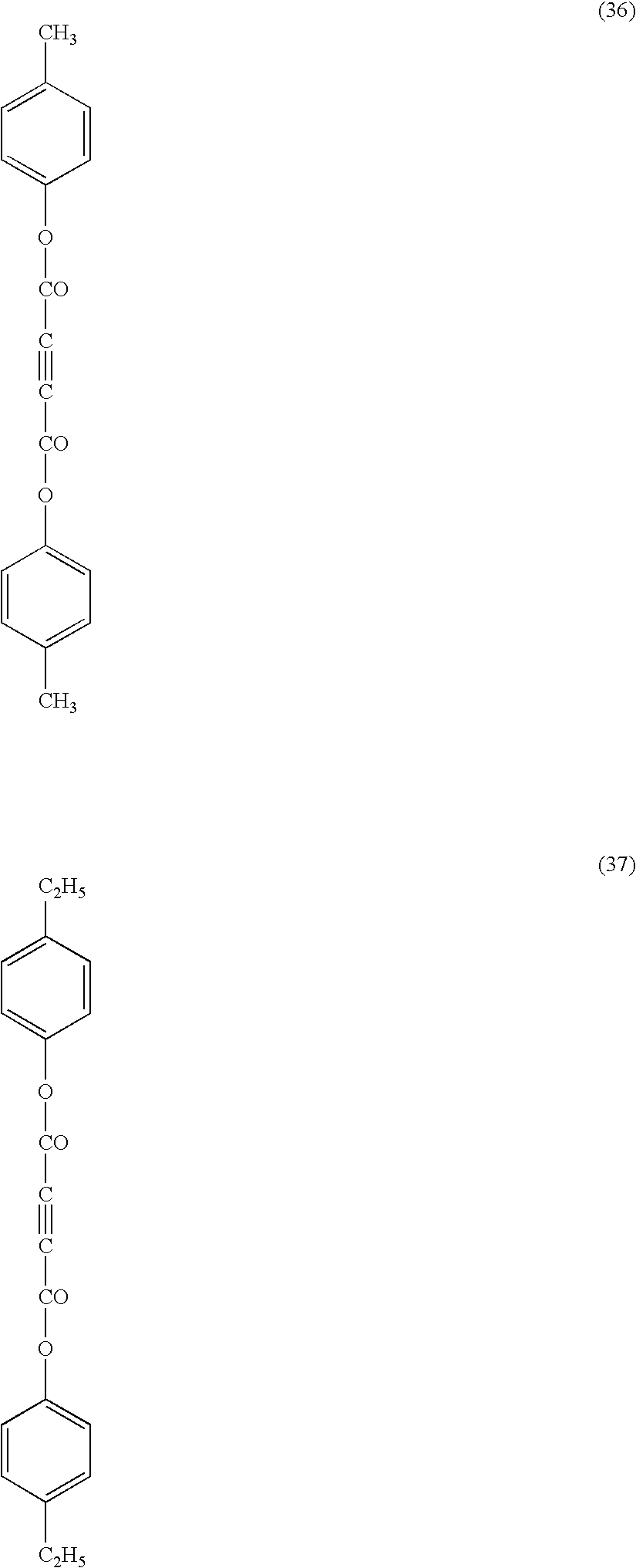


(Evaluation of Phase Retarder)
| TABLE 1 | |
| (23-trans) | |
| | |
| (29-trans) | |
| | |
| (Ref-2) | |
| | |
| Absorption | ||||
| Amount of | Wavelength | coefficient | ||
| additive | of absorp- | (ε) at ab- | ||
| (weight | tion maxi- | sorption | ||
| Film | Additive | parts) | mum (λmax) | maximum |
| Example 1 | 10-trans | 1.8 | 220 nm | 15,000 |
| Example 2 | 23-trans | 2.3 | 230 nm | 16,000 |
| Example 3 | 29-trans | 2.0 | 240 nm | 20,000 |
| Comp. Ex. 1 | Ref-1 | 1.2 | 280 nm | 60,000 |
| Comp. Ex. 2 | Ref-1 | 1.8 | 280 nm | 60,000 |
| Comp. Ex. 3 | Ref-2 | 1.6 | 280 nm | 60,000 |
| Retardation |
| Film | 450 nm | 550 nm | 590 nm | Coloring* |
| Example 1 | 111.6 nm | 137.3 nm | 146.2 nm | A |
| Example 2 | 112.6 nm | 137.5 nm | 144.2 nm | A |
| Example 3 | 113.6 nm | 137.6 nm | 143.1 nm | A |
| Comp. Example 1 | 109.4 nm | 125.3 nm | 130.2 nm | C |
| Comp. Example 2 | 120.6 nm | 137.2 nm | 140.2 nm | B |
| Comp. Example 3 | 122.4 nm | 137.1 nm | 141.0 nm | B |
| Theoretical λ/4 | 112.5 nm | 137.5 nm | 147.5 nm | |
| Remarks: (coloring*) | ||||
| A: undesirable colors are observed in neither dark, bright nor medium tone images; | ||||
| B: bluish and yellowish undesirable colors are observed in bright and dark images, respectively; and | ||||
| C: undesirable colors are observed in dark, bright and medium tone images, and all the images exhibited low contrast. | ||||
[Auxiliary Experiment]
(Spectrum of Retardation-Increasing Agent)
| TABLE 2 | |
| (10-trans) | |
|
|
|
| (41-trans) | |
|
|
|
| (29-trans) | |
|
|
|
| Retardation | Absorption co- | |
| increasing | Wavelength of absorp- | efficient (ε) at ab- |
| agent | tion maximum (λmax) | sorption maximum |
| 10-trans | 220 nm | 15,000 |
| 41-trans | 230 nm | 16,000 |
| 29-trans | 240 nm | 20,000 |


Claims (7)
Ar1—L2—X—L3—Ar2 (II)
Priority Applications (2)
| Application Number | Priority Date | Filing Date | Title |
|---|---|---|---|
| US11/368,633 US7559986B2 (en) | 2001-03-14 | 2006-03-07 | Phase difference plate comprising polymer film containing compound having rod-shaped molecular structure |
| US12/379,145 US7943210B2 (en) | 2001-03-14 | 2009-02-13 | Phase difference plate comprising polymer film containing compound having rod-shaped molecular structure |
Applications Claiming Priority (9)
| Application Number | Priority Date | Filing Date | Title |
|---|---|---|---|
| JP2001072391 | 2001-03-14 | ||
| JP2001-72392 | 2001-03-14 | ||
| JP2001072392A JP2002267847A (en) | 2001-03-14 | 2001-03-14 | Phase difference plate, circularly polarizing plate and reflection liquid crystal display device |
| JP2001-72391 | 2001-03-14 | ||
| JP2001249273A JP2003058320A (en) | 2001-08-20 | 2001-08-20 | Touch panel and reflective liquid crystal display device |
| JP2001-249273 | 2001-08-20 | ||
| PCT/JP2002/002411 WO2002073252A1 (en) | 2001-03-14 | 2002-03-14 | Phase difference plate comprising polymer film containing compound having rod-shaped molecular structure |
| US10/471,560 US7060333B2 (en) | 2001-03-14 | 2002-03-14 | Phase difference plate comprising polymer film containing compound having rod-shaped molecular structure |
| US11/368,633 US7559986B2 (en) | 2001-03-14 | 2006-03-07 | Phase difference plate comprising polymer film containing compound having rod-shaped molecular structure |
Related Parent Applications (3)
| Application Number | Title | Priority Date | Filing Date |
|---|---|---|---|
| US10471560 Division | 2002-03-14 | ||
| PCT/JP2002/002411 Division WO2002073252A1 (en) | 2001-03-14 | 2002-03-14 | Phase difference plate comprising polymer film containing compound having rod-shaped molecular structure |
| US10/471,560 Division US7060333B2 (en) | 2001-03-14 | 2002-03-14 | Phase difference plate comprising polymer film containing compound having rod-shaped molecular structure |
Related Child Applications (1)
| Application Number | Title | Priority Date | Filing Date |
|---|---|---|---|
| US12/379,145 Division US7943210B2 (en) | 2001-03-14 | 2009-02-13 | Phase difference plate comprising polymer film containing compound having rod-shaped molecular structure |
Publications (2)
| Publication Number | Publication Date |
|---|---|
| US20060144291A1 US20060144291A1 (en) | 2006-07-06 |
| US7559986B2 true US7559986B2 (en) | 2009-07-14 |
Family
ID=27346241
Family Applications (3)
| Application Number | Title | Priority Date | Filing Date |
|---|---|---|---|
| US10/471,560 Expired - Lifetime US7060333B2 (en) | 2001-03-14 | 2002-03-14 | Phase difference plate comprising polymer film containing compound having rod-shaped molecular structure |
| US11/368,633 Expired - Lifetime US7559986B2 (en) | 2001-03-14 | 2006-03-07 | Phase difference plate comprising polymer film containing compound having rod-shaped molecular structure |
| US12/379,145 Expired - Fee Related US7943210B2 (en) | 2001-03-14 | 2009-02-13 | Phase difference plate comprising polymer film containing compound having rod-shaped molecular structure |
Family Applications Before (1)
| Application Number | Title | Priority Date | Filing Date |
|---|---|---|---|
| US10/471,560 Expired - Lifetime US7060333B2 (en) | 2001-03-14 | 2002-03-14 | Phase difference plate comprising polymer film containing compound having rod-shaped molecular structure |
Family Applications After (1)
| Application Number | Title | Priority Date | Filing Date |
|---|---|---|---|
| US12/379,145 Expired - Fee Related US7943210B2 (en) | 2001-03-14 | 2009-02-13 | Phase difference plate comprising polymer film containing compound having rod-shaped molecular structure |
Country Status (8)
| Country | Link |
|---|---|
| US (3) | US7060333B2 (en) |
| EP (1) | EP1369713B1 (en) |
| KR (1) | KR100688114B1 (en) |
| CN (1) | CN1306289C (en) |
| AT (1) | ATE556335T1 (en) |
| AU (1) | AU2002238896A1 (en) |
| TW (1) | TW556005B (en) |
| WO (1) | WO2002073252A1 (en) |
Cited By (5)
| Publication number | Priority date | Publication date | Assignee | Title |
|---|---|---|---|---|
| US8742772B2 (en) | 2011-11-25 | 2014-06-03 | Nitto Denko Corporation | Touch panel sensor |
| US9068063B2 (en) | 2010-06-29 | 2015-06-30 | Eastman Chemical Company | Cellulose ester/elastomer compositions |
| US9273195B2 (en) | 2010-06-29 | 2016-03-01 | Eastman Chemical Company | Tires comprising cellulose ester/elastomer compositions |
| US9708474B2 (en) | 2011-12-07 | 2017-07-18 | Eastman Chemical Company | Cellulose esters in pneumatic tires |
| US10077343B2 (en) | 2016-01-21 | 2018-09-18 | Eastman Chemical Company | Process to produce elastomeric compositions comprising cellulose ester additives |
Families Citing this family (42)
| Publication number | Priority date | Publication date | Assignee | Title |
|---|---|---|---|---|
| JP2003114325A (en) * | 2001-10-03 | 2003-04-18 | Nitto Denko Corp | Laminated quarter-wave plate, circularly polarizing plate and liquid crystal display device using the same, and method for manufacturing the same |
| JP4201171B2 (en) * | 2002-11-08 | 2008-12-24 | 日本化薬株式会社 | Liquid crystalline compounding composition and retardation film using the same |
| KR20050009838A (en) * | 2003-07-18 | 2005-01-26 | 현대자동차주식회사 | monitor with a touch screen improved reflection rate of light |
| CN100445779C (en) * | 2003-08-28 | 2008-12-24 | 日本化药株式会社 | Phase shift films made by using cellulose derivatives |
| US8304040B2 (en) * | 2004-01-26 | 2012-11-06 | Fujifilm Corporation | Polymer film and preparation method of polymer solution |
| JP4759324B2 (en) * | 2004-06-22 | 2011-08-31 | 富士フイルム株式会社 | Polarizing plate and liquid crystal display device |
| TW200617446A (en) * | 2004-06-22 | 2006-06-01 | Fuji Photo Film Co Ltd | Polarizing plate and liquid crystal display device |
| TW200606449A (en) * | 2004-07-01 | 2006-02-16 | Fuji Photo Film Co Ltd | Optical cellulose acylate film, polarizing plate and liquid crystal display |
| US7710371B2 (en) * | 2004-12-16 | 2010-05-04 | Xerox Corporation | Variable volume between flexible structure and support surface |
| CN100432784C (en) * | 2004-12-20 | 2008-11-12 | 日东电工株式会社 | Liquid crystal panel and liquid crystal display apparatus |
| KR20070094825A (en) * | 2005-01-05 | 2007-09-21 | 제이에스알 가부시끼가이샤 | Thermoplastic resin composition, optical film, and process for producing film |
| WO2006090887A1 (en) * | 2005-02-23 | 2006-08-31 | Fujifilm Corporation | Optical compensation sheet and liquid crystal display device |
| JP4699783B2 (en) * | 2005-03-22 | 2011-06-15 | 富士フイルム株式会社 | Cellulose acylate film, polarizing plate and liquid crystal display device |
| TW200700471A (en) * | 2005-03-22 | 2007-01-01 | Fuji Photo Film Co Ltd | Optical compensation film, polarizing plate and liquid crystal display |
| JP4815888B2 (en) * | 2005-06-17 | 2011-11-16 | 富士ゼロックス株式会社 | Display medium, display element, and display method |
| JP4766936B2 (en) * | 2005-07-06 | 2011-09-07 | 富士フイルム株式会社 | Optical film and manufacturing method thereof, optical compensation film, polarizing plate, and liquid crystal display device |
| JPWO2007010839A1 (en) * | 2005-07-21 | 2009-01-29 | コニカミノルタオプト株式会社 | Polarizing plate, liquid crystal display device and method for producing hydrophilic polymer film |
| JP4134133B2 (en) * | 2005-09-29 | 2008-08-13 | 大日本印刷株式会社 | Optical function film and phase difference film |
| JP2009531811A (en) * | 2006-02-22 | 2009-09-03 | サン−ゴバン グラス フランス | Use of organic light emitting devices and transparent conductive layers in organic light emitting devices |
| WO2007145090A1 (en) * | 2006-06-13 | 2007-12-21 | Konica Minolta Opto, Inc. | Cellulose ester film, process for production of cellulose ester film, polarizing plate, and liquid crystal display device |
| JP2009048157A (en) * | 2006-12-21 | 2009-03-05 | Fujifilm Corp | Liquid crystal display |
| JP2009063983A (en) * | 2006-12-21 | 2009-03-26 | Fujifilm Corp | Optical film and polarizing plate having the same |
| JP2008260919A (en) * | 2007-03-16 | 2008-10-30 | Fujifilm Corp | Cellulose acetate propionate film, process for producing cellulose acetate propionate film, optical compensation sheet, polarizing plate and liquid crystal display device |
| US20080311392A1 (en) * | 2007-06-12 | 2008-12-18 | Ming Scientific, Llc | Thermal barrier |
| JP5027086B2 (en) * | 2008-09-25 | 2012-09-19 | 株式会社ジャパンディスプレイウェスト | Input device and display device with input function |
| EP2357499B1 (en) * | 2008-12-09 | 2017-04-19 | Sekisui Chemical Co., Ltd. | Retardation element |
| TWI462887B (en) | 2008-12-22 | 2014-12-01 | Sekisui Chemical Co Ltd | Laminated glass laminate |
| JP5609008B2 (en) * | 2009-05-12 | 2014-10-22 | コニカミノルタ株式会社 | Transparent conductive film, method for producing transparent conductive film, and transparent electrode for electronic device |
| KR100973628B1 (en) * | 2010-01-08 | 2010-08-02 | 최종수 | Apparatus for treating skin |
| JP5677204B2 (en) * | 2010-06-10 | 2015-02-25 | 富士フイルム株式会社 | Stereoscopic image recognition device |
| KR20120044041A (en) * | 2010-10-27 | 2012-05-07 | 삼성모바일디스플레이주식회사 | Display device |
| JP5900890B2 (en) | 2010-11-30 | 2016-04-06 | 日東電工株式会社 | Display panel device having touch input function |
| TWI471602B (en) * | 2012-01-17 | 2015-02-01 | Nat Applied Res Laboratories | Optical film and head up display device |
| JP2014044394A (en) * | 2012-03-30 | 2014-03-13 | Nitto Denko Corp | Long retardation film, circularly polarizing plate and organic electroluminescent (el) panel |
| KR20140013960A (en) * | 2012-07-23 | 2014-02-05 | 주식회사 엘지화학 | High light transmittance and color adjusting circular polarizing plate and reflective liquid crystal displays comprising the same |
| JPWO2014084044A1 (en) * | 2012-11-28 | 2017-01-05 | コニカミノルタ株式会社 | Glass with circular polarization function, organic EL display device and liquid crystal display device |
| JP6119518B2 (en) | 2013-02-12 | 2017-04-26 | ソニー株式会社 | Sensor device, input device and electronic apparatus |
| US10055067B2 (en) | 2013-03-18 | 2018-08-21 | Sony Corporation | Sensor device, input device, and electronic apparatus |
| JP6142745B2 (en) * | 2013-09-10 | 2017-06-07 | ソニー株式会社 | Sensor device, input device and electronic apparatus |
| JP2015190859A (en) | 2014-03-28 | 2015-11-02 | ソニー株式会社 | Sensor device, input device, and electronic apparatus |
| KR102299111B1 (en) * | 2015-01-09 | 2021-09-07 | 삼성디스플레이 주식회사 | Touch panel and organic light emitting diode display |
| KR102566331B1 (en) * | 2019-10-10 | 2023-08-22 | 주식회사 엘지화학 | Transmission Variable Device |
Citations (18)
| Publication number | Priority date | Publication date | Assignee | Title |
|---|---|---|---|---|
| US5412044A (en) | 1992-11-30 | 1995-05-02 | The Dow Chemical Company | Nitro group terminated mesogenic epoxy resin adducts |
| US5852487A (en) | 1996-01-25 | 1998-12-22 | Sharp Kabushiki Kaisha | LCD device having an input function and polymer substrates having dual function |
| JPH1180090A (en) | 1997-09-05 | 1999-03-23 | Dainippon Ink & Chem Inc | Liquid crystalline (meth)acrylate compound, composition containing the same compound and optical isomer using the same |
| US6020945A (en) | 1996-11-11 | 2000-02-01 | Dowa Mining Co., Ltd. | Display device with a transparent optical filter |
| JP2000056301A (en) | 1998-08-04 | 2000-02-25 | Kanegafuchi Chem Ind Co Ltd | Optical device |
| EP0982621A2 (en) | 1998-08-21 | 2000-03-01 | Nippon Mitsubishi Oil Corporation | Film for optical elements |
| DE19941567A1 (en) | 1998-09-05 | 2000-04-20 | Merck Patent Gmbh | New liquid crystal compounds containing 3-hydroxyacrylic acid ester units, having high clear point, dielectric anisotropy and double refraction, useful e.g. in displays or (electro)optical components |
| JP2000111914A (en) | 1998-09-30 | 2000-04-21 | Fuji Photo Film Co Ltd | Retardation raising agent for low fatty acid cellulose ester film, optical compensation sheet and liquid crystal display device |
| JP2000112663A (en) | 1997-11-27 | 2000-04-21 | Kanegafuchi Chem Ind Co Ltd | Transparent touch panel and liquid crystal cell with transparent touch panel |
| JP2000137116A (en) | 1998-10-30 | 2000-05-16 | Teijin Ltd | Phase difference plate and liquid crystal display device using the same |
| JP2000304932A (en) | 1999-02-17 | 2000-11-02 | Fuji Photo Film Co Ltd | Optical compensation sheet, elliptical polarizing plate, and liquid crystal display device |
| WO2000065384A1 (en) | 1999-04-21 | 2000-11-02 | Fuji Photo Film Co., Ltd. | Phase contrast plate comprising one sheet of cellulose ester film containing aromatic compound |
| JP2001098086A (en) | 1999-09-29 | 2001-04-10 | Fuji Photo Film Co Ltd | Method for production of cellulose ester film and method for increasing birefringence of cellulose ester film |
| JP2001154018A (en) | 1999-11-25 | 2001-06-08 | Konica Corp | Optical compensation sheet and liquid crystal display device using the same |
| JP2001154194A (en) | 1999-11-25 | 2001-06-08 | Konica Corp | Optical compensation sheet and liquid crystal display device utilizing the same |
| US6362862B1 (en) | 1996-04-26 | 2002-03-26 | Hitachi, Ltd. | Liquid crystal display |
| JP2002099388A (en) | 2000-07-19 | 2002-04-05 | Fuji Photo Film Co Ltd | Touch panel, reflection type liquid crystal display device and guest host type liquid crystal display device |
| US6844033B2 (en) | 2001-03-01 | 2005-01-18 | Konica Corporation | Cellulose ester film, its manufacturing method, polarizing plate, and liquid crystal display |
Family Cites Families (6)
| Publication number | Priority date | Publication date | Assignee | Title |
|---|---|---|---|---|
| DE69828733T2 (en) * | 1997-10-20 | 2005-12-29 | Fuji Photo Film Co., Ltd., Minami-Ashigara | Optical compensatory sheet and liquid crystal display device |
| JPH11115086A (en) * | 1997-10-20 | 1999-04-27 | Kanegafuchi Chem Ind Co Ltd | Transparent conductive film |
| JPH11134112A (en) * | 1997-10-28 | 1999-05-21 | Teijin Ltd | Input and display integral device |
| JP2000082338A (en) * | 1998-09-07 | 2000-03-21 | Toyobo Co Ltd | Transparent conductive film, transparent touch panel, and liquid crystal display element |
| JP2000099388A (en) * | 1998-09-24 | 2000-04-07 | Yamaha Corp | Filing system |
| KR100655677B1 (en) * | 1999-03-12 | 2006-12-08 | 후지 샤신 필름 가부시기가이샤 | Elliptic polarizer formed of transparent protective layer, polarizer layer, transparent support and optical anisotropic layer of liquid-crystal molecules |
-
2002
- 2002-03-14 TW TW091104799A patent/TW556005B/en not_active IP Right Cessation
- 2002-03-14 CN CNB028064720A patent/CN1306289C/en not_active Expired - Lifetime
- 2002-03-14 KR KR1020037011847A patent/KR100688114B1/en active IP Right Grant
- 2002-03-14 AU AU2002238896A patent/AU2002238896A1/en not_active Abandoned
- 2002-03-14 US US10/471,560 patent/US7060333B2/en not_active Expired - Lifetime
- 2002-03-14 EP EP02705178A patent/EP1369713B1/en not_active Expired - Lifetime
- 2002-03-14 AT AT02705178T patent/ATE556335T1/en active
- 2002-03-14 WO PCT/JP2002/002411 patent/WO2002073252A1/en active Application Filing
-
2006
- 2006-03-07 US US11/368,633 patent/US7559986B2/en not_active Expired - Lifetime
-
2009
- 2009-02-13 US US12/379,145 patent/US7943210B2/en not_active Expired - Fee Related
Patent Citations (21)
| Publication number | Priority date | Publication date | Assignee | Title |
|---|---|---|---|---|
| US5464912A (en) | 1992-11-30 | 1995-11-07 | The Dow Chemical Company | Amines from nitro group terminated mesogenic epoxy resin adducts with reduced hydroxyl group functionality |
| US5412044A (en) | 1992-11-30 | 1995-05-02 | The Dow Chemical Company | Nitro group terminated mesogenic epoxy resin adducts |
| US5852487A (en) | 1996-01-25 | 1998-12-22 | Sharp Kabushiki Kaisha | LCD device having an input function and polymer substrates having dual function |
| US6362862B1 (en) | 1996-04-26 | 2002-03-26 | Hitachi, Ltd. | Liquid crystal display |
| US6020945A (en) | 1996-11-11 | 2000-02-01 | Dowa Mining Co., Ltd. | Display device with a transparent optical filter |
| JPH1180090A (en) | 1997-09-05 | 1999-03-23 | Dainippon Ink & Chem Inc | Liquid crystalline (meth)acrylate compound, composition containing the same compound and optical isomer using the same |
| JP2000112663A (en) | 1997-11-27 | 2000-04-21 | Kanegafuchi Chem Ind Co Ltd | Transparent touch panel and liquid crystal cell with transparent touch panel |
| JP2000056301A (en) | 1998-08-04 | 2000-02-25 | Kanegafuchi Chem Ind Co Ltd | Optical device |
| EP0982621A2 (en) | 1998-08-21 | 2000-03-01 | Nippon Mitsubishi Oil Corporation | Film for optical elements |
| DE19941567A1 (en) | 1998-09-05 | 2000-04-20 | Merck Patent Gmbh | New liquid crystal compounds containing 3-hydroxyacrylic acid ester units, having high clear point, dielectric anisotropy and double refraction, useful e.g. in displays or (electro)optical components |
| JP2000111914A (en) | 1998-09-30 | 2000-04-21 | Fuji Photo Film Co Ltd | Retardation raising agent for low fatty acid cellulose ester film, optical compensation sheet and liquid crystal display device |
| JP2000137116A (en) | 1998-10-30 | 2000-05-16 | Teijin Ltd | Phase difference plate and liquid crystal display device using the same |
| JP2000304932A (en) | 1999-02-17 | 2000-11-02 | Fuji Photo Film Co Ltd | Optical compensation sheet, elliptical polarizing plate, and liquid crystal display device |
| WO2000065384A1 (en) | 1999-04-21 | 2000-11-02 | Fuji Photo Film Co., Ltd. | Phase contrast plate comprising one sheet of cellulose ester film containing aromatic compound |
| EP1182470A1 (en) | 1999-04-21 | 2002-02-27 | Fuji Photo Film Co., Ltd. | Phase contrast plate comprising one sheet of cellulose ester film containing aromatic compound |
| US7166339B1 (en) * | 1999-04-21 | 2007-01-23 | Fuji Photo Film Co Ltd | Phase contrast plate comprising one sheet of cellulose ester film containing aromatic compound |
| JP2001098086A (en) | 1999-09-29 | 2001-04-10 | Fuji Photo Film Co Ltd | Method for production of cellulose ester film and method for increasing birefringence of cellulose ester film |
| JP2001154018A (en) | 1999-11-25 | 2001-06-08 | Konica Corp | Optical compensation sheet and liquid crystal display device using the same |
| JP2001154194A (en) | 1999-11-25 | 2001-06-08 | Konica Corp | Optical compensation sheet and liquid crystal display device utilizing the same |
| JP2002099388A (en) | 2000-07-19 | 2002-04-05 | Fuji Photo Film Co Ltd | Touch panel, reflection type liquid crystal display device and guest host type liquid crystal display device |
| US6844033B2 (en) | 2001-03-01 | 2005-01-18 | Konica Corporation | Cellulose ester film, its manufacturing method, polarizing plate, and liquid crystal display |
Non-Patent Citations (3)
| Title |
|---|
| English language translation of the International Preliminary Examination Report mailed Dec. 17, 2003 in International Application No. PCT/JP02/02411. |
| Hiroshi et al. Machine Translation of JP 11-080090, Mar. 23, 1999. * |
| Search Report Issued in International Application No. PCT/JP02/02411, Jul. 9, 2002. |
Cited By (10)
| Publication number | Priority date | Publication date | Assignee | Title |
|---|---|---|---|---|
| US9068063B2 (en) | 2010-06-29 | 2015-06-30 | Eastman Chemical Company | Cellulose ester/elastomer compositions |
| US9200147B2 (en) | 2010-06-29 | 2015-12-01 | Eastman Chemical Company | Processes for making cellulose ester compositions |
| US9273195B2 (en) | 2010-06-29 | 2016-03-01 | Eastman Chemical Company | Tires comprising cellulose ester/elastomer compositions |
| US8742772B2 (en) | 2011-11-25 | 2014-06-03 | Nitto Denko Corporation | Touch panel sensor |
| US9708474B2 (en) | 2011-12-07 | 2017-07-18 | Eastman Chemical Company | Cellulose esters in pneumatic tires |
| US9708473B2 (en) | 2011-12-07 | 2017-07-18 | Eastman Chemical Company | Cellulose esters in pneumatic tires |
| US9708472B2 (en) | 2011-12-07 | 2017-07-18 | Eastman Chemical Company | Cellulose esters in highly-filled elastomeric systems |
| US9708475B2 (en) | 2011-12-07 | 2017-07-18 | Eastman Chemical Company | Cellulose esters in highly-filled elastomeric systems |
| US10077343B2 (en) | 2016-01-21 | 2018-09-18 | Eastman Chemical Company | Process to produce elastomeric compositions comprising cellulose ester additives |
| US10077342B2 (en) | 2016-01-21 | 2018-09-18 | Eastman Chemical Company | Elastomeric compositions comprising cellulose ester additives |
Also Published As
| Publication number | Publication date |
|---|---|
| EP1369713B1 (en) | 2012-05-02 |
| US7060333B2 (en) | 2006-06-13 |
| CN1516816A (en) | 2004-07-28 |
| WO2002073252A1 (en) | 2002-09-19 |
| ATE556335T1 (en) | 2012-05-15 |
| TW556005B (en) | 2003-10-01 |
| CN1306289C (en) | 2007-03-21 |
| KR100688114B1 (en) | 2007-03-02 |
| US20090163703A1 (en) | 2009-06-25 |
| US20040096594A1 (en) | 2004-05-20 |
| AU2002238896A1 (en) | 2002-09-24 |
| EP1369713A1 (en) | 2003-12-10 |
| EP1369713A4 (en) | 2006-06-07 |
| US20060144291A1 (en) | 2006-07-06 |
| KR20030084977A (en) | 2003-11-01 |
| US7943210B2 (en) | 2011-05-17 |
Similar Documents
| Publication | Publication Date | Title |
|---|---|---|
| US7559986B2 (en) | Phase difference plate comprising polymer film containing compound having rod-shaped molecular structure | |
| US7166321B2 (en) | Process for the preparation of an optical compensatory sheet comprising cellulose ester film, orientation layer, and optically anisotropic layer formed of liquid crystal molecules having a fixed alignment | |
| US7504139B2 (en) | Optical cellulose acylate film, polarizing plate and liquid crystal display | |
| KR100961426B1 (en) | Optical compensatory sheet comprising polymer film | |
| US7611760B2 (en) | Cellulose acylate film, optical compensation film, polarizing plate and liquid crystal display | |
| US20070258141A1 (en) | Polarizing Plate and Liquid Crystal Display | |
| JP4759324B2 (en) | Polarizing plate and liquid crystal display device | |
| US20070259134A1 (en) | Cellulose Compound Film, Optical Compensation Sheet, Polarizing Plate, and Liquid Crystal Display Device | |
| JP2002048913A (en) | Retardation film, circularly polarizing plate and reflective liquid crystal display device | |
| WO2005114272A1 (en) | Polarizing plate and liquid crystal display | |
| WO2006033313A1 (en) | Polarizing plate and liquid crystal display | |
| US20080062355A1 (en) | Polarizing Plate and Liquid Crystal Display | |
| JP2002099388A (en) | Touch panel, reflection type liquid crystal display device and guest host type liquid crystal display device | |
| JP2002071949A (en) | Optical compensation sheet, polarizing plate and liquid crystal display device using the same | |
| JP2002267847A (en) | Phase difference plate, circularly polarizing plate and reflection liquid crystal display device | |
| JP2002277632A (en) | Optical compensation sheet, method for manufacturing the same, polarizing plate and liquid crystal display | |
| JP2005134863A (en) | Optical compensation sheet, polarizing plate and liquid crystal display | |
| JP2023029317A (en) | Optical film, circular polarizing plate, and display device | |
| KR100810484B1 (en) | Phase difference plate constituted of one sheet of polymer film | |
| JP2003058320A (en) | Touch panel and reflective liquid crystal display device | |
| JP5171272B2 (en) | Optical film, retardation film, polarizing plate, and liquid crystal display device | |
| JP2002062431A (en) | Optical compensation sheet, polarizing plate and liquid crystal display device using the same | |
| JP2006039518A (en) | Polarizing plate and liquid crystal display | |
| JP2004045987A (en) | Touch panel-integrated transmission type liquid crystal display | |
| JP2005266502A (en) | Polarizing plate and liquid crystal display device |
Legal Events
| Date | Code | Title | Description |
|---|---|---|---|
| AS | Assignment |
Owner name: FUJIFILM HOLDINGS CORPORATION, JAPAN Free format text: CHANGE OF NAME AS SHOWN BY THE ATTACHED CERTIFICATE OF PARTIAL CLOSED RECORDS AND THE VERIFIED ENGLISH TRANSLATION THEREOF;ASSIGNOR:FUJI PHOTO FILM CO., LTD.;REEL/FRAME:018942/0958 Effective date: 20061001 Owner name: FUJIFILM HOLDINGS CORPORATION,JAPAN Free format text: CHANGE OF NAME AS SHOWN BY THE ATTACHED CERTIFICATE OF PARTIAL CLOSED RECORDS AND THE VERIFIED ENGLISH TRANSLATION THEREOF;ASSIGNOR:FUJI PHOTO FILM CO., LTD.;REEL/FRAME:018942/0958 Effective date: 20061001 |
|
| AS | Assignment |
Owner name: FUJIFILM CORPORATION, JAPAN Free format text: ASSIGNMENT OF ASSIGNORS INTEREST;ASSIGNOR:FUJIFILM HOLDINGS CORPORATION;REEL/FRAME:019193/0322 Effective date: 20070315 Owner name: FUJIFILM CORPORATION,JAPAN Free format text: ASSIGNMENT OF ASSIGNORS INTEREST;ASSIGNOR:FUJIFILM HOLDINGS CORPORATION;REEL/FRAME:019193/0322 Effective date: 20070315 |
|
| FEPP | Fee payment procedure |
Free format text: PAYOR NUMBER ASSIGNED (ORIGINAL EVENT CODE: ASPN); ENTITY STATUS OF PATENT OWNER: LARGE ENTITY |
|
| STCF | Information on status: patent grant |
Free format text: PATENTED CASE |
|
| FPAY | Fee payment |
Year of fee payment: 4 |
|
| FPAY | Fee payment |
Year of fee payment: 8 |
|
| MAFP | Maintenance fee payment |
Free format text: PAYMENT OF MAINTENANCE FEE, 12TH YEAR, LARGE ENTITY (ORIGINAL EVENT CODE: M1553); ENTITY STATUS OF PATENT OWNER: LARGE ENTITY Year of fee payment: 12 |