US7561586B2 - Method and apparatus for providing network VPN services on demand - Google Patents
Method and apparatus for providing network VPN services on demand Download PDFInfo
- Publication number
- US7561586B2 US7561586B2 US10/666,529 US66652903A US7561586B2 US 7561586 B2 US7561586 B2 US 7561586B2 US 66652903 A US66652903 A US 66652903A US 7561586 B2 US7561586 B2 US 7561586B2
- Authority
- US
- United States
- Prior art keywords
- vpn
- network
- sip
- application
- gateway
- Prior art date
- Legal status (The legal status is an assumption and is not a legal conclusion. Google has not performed a legal analysis and makes no representation as to the accuracy of the status listed.)
- Expired - Fee Related, expires
Links
Images


Classifications
-
- H—ELECTRICITY
- H04—ELECTRIC COMMUNICATION TECHNIQUE
- H04L—TRANSMISSION OF DIGITAL INFORMATION, e.g. TELEGRAPHIC COMMUNICATION
- H04L12/00—Data switching networks
- H04L12/28—Data switching networks characterised by path configuration, e.g. LAN [Local Area Networks] or WAN [Wide Area Networks]
- H04L12/46—Interconnection of networks
- H04L12/4604—LAN interconnection over a backbone network, e.g. Internet, Frame Relay
- H04L12/4608—LAN interconnection over ATM networks
Definitions
- the present invention relates to communication networks and, more particularly, to a method and apparatus for providing network VPN services on demand.
- Data communication networks may include various computers, servers, nodes, routers, switches, hubs, proxies, and other devices coupled to and configured to pass data to one another. These devices will be referred to herein as “network devices.” Data is communicated through the data communication network by passing data packets (or data cells or segments) between the network devices by utilizing one or more communication links. A particular data packet may be handled by multiple network devices and cross multiple communication links as it travels between its source and its destination over the network.
- the various network devices on the communication network communicate with each other using predefined sets of rules, referred to herein as protocols.
- Different protocols are used to govern different aspects of the communication, such as how signals should be formed for transmission between network devices, various aspects of what the data packets should look like, and how packets should be handled or routed through the network by the network devices.
- a secure path through an untrusted network may be formed by securing communication resources between two or more networks or network devices to form a VPN tunnel, such as by encrypting or encapsulating transmissions between the networks or network devices.
- VPN tunnels over a public network such as the Internet enables information to be exchanged securely between geographically dispersed sites without obtaining dedicated resources through the public network.
- Enterprise VPNs Enterprise Virtual Private Networks
- Enterprise VPNs may be used, for example, to share computational resources, storage resources, programs, and database resources.
- Enterprise networks focus on application-related issues, such as distributed workflow logic and resource management, coordinated fail-over between participants, problem determination, Quality of Service (QoS), and common security semantics.
- QoS Quality of Service
- Several examples of enterprise VPNs include emerging technologies like GRID services and Web services.
- a service VPN (S-VPN) gateway integrates SIP signaling between applications and network VPN UNI and NNI signaling to enable applications to use SIP signaling to invoke network VPN resources.
- the S-VPN also manages the mapping between SIP signaling and network VPN to manage network VPN resources on behalf of the enterprise VPN applications.
- the mapping relationship reflects the access of user applications to the specific VPN tunnels, multiplexing of media service sessions to VPN tunnels, VPN service creation, service duration, VPN QoS, VPN service life cycle management, and VPN service charge based on a per-service-usage.
- the S-VPN also provides VPN access policy/security management (i.e., inter-domain AAA process), VPN membership auto-discovery, service auto-discovery, network resource auto-discovery, address resolution service for both SIP and VPN naming space, VPN service mobility, and SLA management.
- VPN access policy/security management i.e., inter-domain AAA process
- VPN membership auto-discovery i.e., service auto-discovery
- network resource auto-discovery i.e., address resolution service for both SIP and VPN naming space
- VPN service mobility i.e., VPN service mobility
- SLA management i.e., inter-domain AAA process
- the S-VPN enables network VPN tunnels to be created in advanced and accessed on-demand, for example by enterprise VPN applications such as GRID applications, through a SIP interface.
- FIG. 1 is a functional block diagram of an example of a communication network including S-VPN gateways and illustrating the operations performed in establishing network VPN tunnels according to an embodiment of the invention
- FIG. 2 is a functional block diagram of an example of a communication network including S-VPN gateways and illustrating the operations performed in utilizing network VPN tunnels according to an embodiment of the invention
- FIG. 3 is a functional block diagram illustrating signaling that may take place in the control plane of various network devices according to an embodiment of the invention
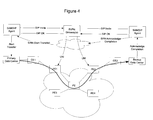
- FIG. 4 is a functional block diagram of an example of how an embodiment of the invention may be used to transfer information between two participants in a storage area network;
- FIG. 5 is a functional block diagram of an example of how an embodiment of the invention may be used to transfer information between three enterprise VPN participants.
- FIG. 6 is a functional block diagram of a S-VPN gateway network device according to an embodiment of the invention.
- a Service Virtual Private Network (S-VPN) gateway enables enterprise VPN applications to access network VPN resources on demand without requiring the enterprise VPN applications to manage the network VPN resources.
- the S-VPN gateway integrates SIP signaling with network VPN UNI/NNI signaling to enable enterprise VPN applications to use SIP signaling to obtain network VPN resources. This allows enterprise VPN applications to use familiar SIP signaling to obtain access to network VPN resources without understanding the nature or details associated with the network VPN resources. Accordingly, accessing network VPN resources can be as simple (to the enterprise VPN application) as establishing a VoIP call.
- integrating enterprise VPNs and network VPNs is performed through a combination of two logical events.
- network VPN tunnels label switched paths (LSPs)
- LSPs label switched paths
- resources on the network VPN tunnels are reserved to handle traffic between the participants in the enterprise VPN so that traffic may be passed between the participants.
- LSPs label switched paths
- These events may occur in a relatively contemporaneous manner so that a given exchange/request can be used to both establish a network VPN tunnel and reserve resources through the tunnel so that the network VPN tunnel may be used directly thereafter.
- the tunnels may be established so that they are available, and utilized as necessary by the enterprise VPN participants.
- the invention is not limited to using tunnels directly after they are created, or to waiting a predetermined period before the tunnels are utilized.
- the network that will handle the traffic for the network VPN is a Multi-Protocol Label Switched (MPLS) network and that the network VPN tunnels will be Label Switched Paths (LSPs) through the MPLS network.
- MPLS Multi-Protocol Label Switched
- LSPs Label Switched Paths
- FIG. 1 illustrates an example network 10 including S-VPN gateways 22 according to an embodiment of the invention.
- the invention is not limited to the network illustrated in FIG. 1 .
- FIG. 1 several arrows are used to show the exchange of information between participants in the network. Other exchanges are possible as well, and the invention is not limited to an embodiment utilizing all of these or only these particular exchanges of information.
- an enterprise VPN application 24 when an enterprise VPN application 24 wishes to join a network VPN, it must first register its association on the network 20 .
- the enterprise VPN application knows the VPN-ID of the network VPN it wishes to join. If the application does not know the VPN ID, the S-VPN may be used to discover that information on behalf of the application using VPN and network resource discovery protocols.
- the enterprise VPN application 24 transfers the VPN-ID to its associated SIP agent 26 .
- the registration process is illustrated by arrow ( 1 ) in FIG. 1 .
- the application provides the SIP agent with its application-specific address, such as URL or IP address, the VPN ID of the VPN to which it would like access, and the identity of the Customer Edge (CE) network device 28 to which it attaches when it access resources external to the LAN on which it is operating.
- the CE network device may register a portion of this information with the SIP user agent on behalf of the application.
- the CE network device 22 associated with enterprise VPN application A has been designated “CE 1 .”
- the SIP agent 26 Upon receipt of this information, the SIP agent 26 registers the enterprise VPN application address, VPN-ID, and CE-ID with a S-VPN gateway 22 associated with CE 1 . This exchange is designated by arrow ( 2 ) in FIG. 1 .
- the S-VPN gateway 22 distributes the CE-ID and VPN-ID to associated Provider Edge (PE) network device(s) 30 .
- PE Provider Edge
- MP-BGP Multi-Protocol Border Gateway Protocol
- MP-BGP enables BGP to carry routing information for multiple network layer routing protocols, e.g. IPv6, IPX, VPN-IPv4, and other similar protocols.
- the invention is not limited to this embodiment, but rather extends to all routing protocols that may be used to exchange routing information between the PE network devices and between the S-VPN gateway 22 and PE network devices 30 .
- the PE network device 30 exchanges (arrow 4 ) this new route information throughout the MPLS domain.
- the other PE network devices 30 will import the route into their routing tables in a known fashion.
- the route information may also be passed to the other S-VPNs (arrow 5 ).
- the service provider uses the routing information and VPN-ID information to set up VPN tunnels throughout the network 20 . Where one of the participants in the network moves, re-registration with a S-VPN at the new location causes the associated VPN tunnels to be redirected to the new location. Accordingly, the S-VPN is able to support VPN mobility.
- FIG. 2 illustrates an example of how an enterprise VPN application may obtain network VPN resources associated with a registered VPN-ID.
- SIP Session Initiation Protocol
- IETF Internet Engineering Task Force
- RRC IETF Request For Comments
- SIP is a text-based protocol that is based on HTTP and MIME, which is designed for real-time transmissions and is considerably less complex than H.323 (although the invention does not preclude the use of H.323 instead of SIP).
- SIP uses an URL addressing scheme and is human readable (e.g. sip:vpn1@nortel.com).
- SIP relies on the session description protocol (SDP) which is described in RFC 2327, the content of which is herein incorporated by reference.
- SDP session description protocol
- an application 24 associated with network VPN A when an application 24 associated with network VPN A is required to transmit data to or receive data from another enterprise VPN site, it issues a request to the SIP agent 26 indicating the VPN-ID and VPN transmission parameters, such as the required bandwidth, quality of service, priority, duration, time to start, and other pertinent parameters (arrow 6 ).
- the VPN-ID may be supplied by the SIP agent where the application is only a member of one VPN.
- the SIP agent 26 sends a SIP Invite message (arrow 7 ) to the S-VPN gateway 22 .
- the SIP Invite message may contain the VPN-ID and one or more of the VPN transmission parameters, or optionally additional VPN transmission parameters.
- the S-VPN gateway may evaluate the requested transmission in view of a service level agreement in place with the application, as well as current traffic conditions when deciding whether to provide the requested VPN services.
- Optional services that may be provided by the S-VPN gateway are discussed in greater detail below in connection with FIG. 3 .
- the S-VPN gateway interfaces (arrow 8 ) the PE(s) associated with CE 1 to reserve bandwidth on the network on behalf of the enterprise VPN application 24 .
- the S-VPN gateway uses User to Network Interface (UNI) signaling to interface with PE 1 to cause PE 1 to add a VPN session to the network VPN tunnel associated with the VPN-ID.
- UNI User to Network Interface
- One way of adding a session to a network VPN tunnel is to use Reservation Protocol (RSVP) to reserve bandwidth and to enable traffic engineering to take place on the Label Switched Path (LSP) forming the network VPN tunnel, and to use Label Distribution Protocol (LDP) to distribute LSP labels over the LSP through the MPLS network.
- RSVP Reservation Protocol
- LSP Label Switched Path
- LDP Label Distribution Protocol
- a label distribution protocol is a common set of procedures that may be used by a label switched router (LSR) to inform other LSRs of label bindings it has made.
- LSR label switched router
- LDP Label Distribution Protocol
- LDP can be utilized to establish LSPs through the LSPs established by RSVP.
- RSVP is used to establish routes through the network core
- LDP will automatically establish sessions with the router at the other end of the LSP.
- LDP control packets are routed hop-by-hop, rather than carried through the LSP. This allows the use of simplex (one-way) traffic-engineered LSPs. Traffic in the opposite direction flows through LDP-established LSPs that follow unicast routing rather than through traffic-engineered tunnels.
- the PE adds the LDP connection to the VPN tunnel (connection multiplexing) and forwards the LDP call to the destination PE. In this manner, an LSP is established between the PEs.
- the destination PE will set up a connection with the destination CE and forward the LDP call to the next SVPN server.
- the S-VPN gateway server also issues an invite (arrow 9 ) to the SIP agent of the second application. If the second application is not associated with the same S-VPN gateway, the SIP Invite is passed to the associated S-VPN gateway for the second application. Where the S-VPN gateway is not known to the S-VPN gateway for the first application, the S-VPN gateway will resolve the address by interfacing a location server 32 in a manner consistent with the SIP protocol specification.
- S-VPN gateway When a single S-VPN gateway is used to establish a network VPN between two sites, it will wait for the end PE device (PE 2 ) to respond with the LDP call setup message ( 10 ). Where there are two or more S-VPN gateways involved, as in the embodiment illustrated in FIG. 2 , the second S-VPN will receive the SIP invite ( 9 ) and wait to receive the LDP call setup message ( 10 ).
- the S-VPN gateway Upon receipt of both the SIP Invite and the LDP call setup message, the S-VPN gateway issues a SIP Invite ( 11 ) to the SIP agent for the second application. If the second application is available to participate in the transaction, it issues a SIP OK (arrow 12 ) which is handled by the S-VPN gateway(s) and agents according to the SIP specification. Once the session is established the tunnel is available to be utilized and may be used by the end devices to transfer data.
- the SIP agents 26 Upon receipt of the SIP OK, the SIP agents 26 will notify their respective applications that the network VPN has been successfully established ( 13 ).
- the SIP Agents may include transfer information, such as bandwidth information, where that information is different than the request information contained in the initial API.
- the first application Upon receipt of the network VPN confirmation ( 13 ) the first application will transmit data to the second application over the network VPN tunnel ( 14 , 15 , 16 ).
- the application When the application is finished transmitting data, it terminates the call by issuing a SIP terminate and releases the VPN resources reserved in the MPLS core.
- FIG. 3 illustrates signaling plane exchanges between network devices configured to implement an embodiment of the invention.
- an end user network device running an application such as a Grid application desires to access network VPN resources
- the end user network device (which also operates as the SIP client in this embodiment) issues a request to an associated SIP agent using a conventional protocol, such as Web Services Description Language (WSDL) or Simple Object Access Protocol (SOAP) (arrow 1 ).
- WSDL Web Services Description Language
- SOAP Simple Object Access Protocol
- the SIP agent issues a SIP invite message ( 2 ) to a S-VPN gateway.
- the S-VPN gateway accesses application—VPN databases to determine which VPNs are associated with the application that caused the SIP agent to issue the invite ( 3 ).
- the S-VPN gateway performs address management services for both the SIP naming space and the VPN naming space, and performs the necessary translations, lookups, and other functions on behalf of the network participants. To facilitate these services, the S-VPN gateway maintains several tables to allow it to manage the mapping between SIP session and VPN, between application and VPN, and various other aspects associated with VPN services to be provided to the application.
- the S-VPN includes a set of tables/databases containing information such as:
- the S-VPN gateway To issue a SIP call, the S-VPN gateway needs to know the address of the target application, or at least of the next S-VPN that will handle the SIP call on behalf of the target application. If the S-VPN gateway knows the address it may issue the call directly by issuing a SIP invite ( 4 ). Where this information is not available, the S-VPN engages in SIP component discovery ( 5 ) to obtain the required information prior to issuing the SIP invite ( 4 ). Where the target application has not registered with a S-VPN agent, and hence is not registered with the location server 32 , the S-VPN may obtain target application VPN information and network resource information using a standard network VPN discovery, and network resource discovery protocol.
- the S-VPN gateway may also perform various services on the network ( 6 ) to ensure that the VPN resource request is valid, such as by ascertaining AAA information associated with the request, applying policy, evaluating whether there are sufficient bandwidth resources available to satisfy the requested/required QoS, and establishing accounting entries to enable the application ultimately to be charged for the services to be performed.
- these additional services such as the establishment of accounting entries, may be performed after the network VPN resources have been reserved ( 14 ).
- the S-VPN gateway must also establish a Label Switched Path (LSP) through the network, distribute labels for use on that path, and reserve resources along that path to enable the enterprise VPN application to send data to the EUND target.
- LSP Label Switched Path
- the established LSP can be either unidirectional or bi-directional, based on service requirements set forth in the SIP session request.
- the new route will be distributed on the network using BGP as discussed above in connection with FIG. 1 .
- the S-VPN will use UNI signaling to cause a LDP call to be issued on the network to distribute labels to establish a LSP on the network as discussed above in connection with FIG. 2 .
- the S-VPN gateway will issue a UNI signal via media signaling gateway ( 8 ) to the PE network device associated with the CE that will be handling the traffic on behalf of the initiating application.
- the LDP call is used to distribute MPLS labels along the LSP between the ingress PE network device and the egress network device, as determined by the PE network device from its routing module.
- RSVP-TE may be used to reserve bandwidth along this path in the network. Reserving bandwidth enables the network to guarantee bandwidth availability, quality of service (QoS), and other attributes associated with the LSP so that transmissions may be handled by the MPLS network in a predictable fashion.
- QoS quality of service
- the S-VPN gateway may interface with its policy, AAA, QoS, and charging module ( 14 ) to ascertain if the network VPN resources should be provided to the initiating application.
- Interfacing with these control facilities at this stage enables the S-VPN to establish accounting entries only after the VPN resources have been provisioned and, may allow the network to respond with anticipated costs associated with the reserved resources.
- Interfacing with these control facilities earlier in the process, as described above reduces network resource allocation where the requesting application fails to obtain approval from the control facilities.
- the requesting application may be requesting bandwidth and/or QoS that exceeds its Service Level Agreement (SLA). In this instance the network may not agree to provide the requested network VPN resources.
- SLA Service Level Agreement
- the requesting application may not be able to authenticate itself sufficiently to access a particular network VPN, or may not be authorized to access the requested network VPN. Establishing this at an earlier stage minimizes setup costs associated with the network provider by filtering out requests that have been improperly requested.
- the S-VPN may also participate in the VPN tunnel monitoring and management to monitor use of the VPN tunnel and meter bandwidth usage on the tunnel. Monitoring bandwidth enables the S-VPN gateway to enter use-based information in the accounting entries to properly charge for use of the VPN resources.
- the label mapping is returned to the S-VPN gateway which will be used by the initiating application or associated CE to place traffic onto the tunnel through the network.
- the S-VPN gateway distributes routes associated with VPN-IDs to enable the PEs to establish network VPN tunnels.
- the S-VPN gateway interfaces with the other SIP servers and network devices to allocate bandwidth over the network VPN tunnels on demand. From an application stand-point, both of these conceptual steps are associated with one or more SIP calls, thus enabling the application to utilize standard SIP signaling to obtain access to network VPN resources. While an embodiment of the invention has been described as using SIP to request resources, BGP to distribute routing information, and UNI/LDP/RSVP to secure network resources to fulfill the network VPN requests, the invention is not limited to this example as many other protocols may be utilized and the invention is not limited to an embodiment formed to function using only the above-listed protocols.
- FIG. 4 illustrates one such example, in which a storage area network seeks to transfer data across a communications network from a primary data center to a backup data center.
- VPN-ID and route information is passed from the S-VPN gateway to the communication network to enable the routing information and VPN tables on the network devices to be updated to include the new route information.
- the primary data center When the primary data center is ready to transfer data to the backup data center, or is ready to schedule a transfer of data to the backup data center, the primary data center creates an API containing information associated with the transfer, such as the amount of data to be transferred, the bandwidth required, the quality of service required, the estimated duration of the transfer, and any other pertinent information.
- the API is received by the SAN/SIP agent which initiates a SIP session by sending a SIP invite to the S-VPN gateway.
- the S-VPN gateway receives the SIP invite and communicates with the relevant PE network devices to cause them to reserve bandwidth on the communication network for the requested transfer.
- the reservations may take place using LDP/RSVP as described above.
- the S-VPN gateway When the network resources have been reserved, the S-VPN gateway issues a SIP invite to the SAN/SIP agent for the backup data center. If the backup data center is able to participate in the transfer, it acknowledges the SIP invite and instructs its SAN/SIP agent to issue a SIP OK. The S-VPN gateway then issues a SIP OK to the SAN/SIP agent associated with the primary data center and the SAN/SIP agent instructs the primary data center to begin transfer of the data to the backup data center through its associated CE network device CE 1 .
- the backup data center Upon completion, the backup data center acknowledges completion of the transfer and the SAN/SIP agents and S-VPN gateway instruct the network that the network resources are no longer necessary.
- the network resources may be allocated to other uses and other users.
- the primary data center issues an API to the SAN/SIP agent indicating a need for resources.
- the primary data center receives back a message from the SAN/SIP agent when it is OK for the primary data center to start the transfer to the backup data center. After the transfer has completed, the primary data center receives a transmission acknowledgment from the backup data center.
- network VPN resources are transparently available on-demand without requiring the application to be cognizant or aware of the network details.
- FIG. 5 illustrates another example of how an embodiment of the invention may be utilized.
- an application at site A would like to transfer information to site B using VPN B and to site C using VPN C.
- the Application issues an API to the SIP agent containing the pertinent information for the transfer over VPN B and for the transfer over VPN C.
- the SIP agent passes this information into one or more SIP invite messages which are passed to the S-VPN gateway.
- the S-VPN gateway reserves VPN resources on behalf of the application for the transfers on the two VPNs, and issues SIP calls to the appropriate S-VPN agents for the sites. All of the details of how the signals are passed between the various participants are the same as discussed above, except that the S-VPN gateway is handling multiple requests for a given application at the same time.
- a single S-VPN gateway has been illustrated as providing S-VPN services to a given site.
- the invention is not limited in this manner, as additional S-VPN gateways may also be configured to provide redundancy should there be a problem with the primary S-VPN gateway or with obtaining access to the primary S-VPN gateway.
- the S-VPN gateway may be located at any convenient location on the network.
- a service provider will generally maintain a centralized VPN management center to manage VPN services for subscribers.
- the VPN management center generally functions to configure the CE network devices, handle communications between VPN customers and the service provider, monitor the status of the VPN networks, and provide any other services necessary or convenient to the VPN network and customers.
- the S-VPN gateway may be collocated with the service provider's VPN management center to facilitate communications between the S-VPN gateway and the other devices in the VPN management center, although the invention is not limited in this regard.
- the packets to be transmitted may be encapsulated using a protocol such as Generic Routing Encapsulation (GRE), which allows an arbitrary network protocol A to be transmitted over any other arbitrary network protocol B, by encapsulating the packets of A within GRE packets, which in turn are contained within packets of B.
- GRE Generic Routing Encapsulation
- the type of encapsulation or encryption to be used for the VPN may be communicated between the end points using a tunnel type attribute.
- FIG. 6 illustrates one embodiment of a network device configured to implement a S-VPN gateway according to an embodiment of the invention.
- the S-VPN gateway 22 in this embodiment includes a processor 40 containing control logic 42 configured to implement the functions ascribed to the S-VPN gateway 22 discussed herein in connection with FIGS. 1-5 .
- the S-VPN gateway may be a personal computer, server, or other processing device, capable of processing instructions to implement the functions of the S-VPN gateway 22 discussed herein.
- the S-VPN gateway may be embodied on a network device including a switch fabric or other hardware, firmware, and/or software, to enable the network device to perform functions commonly ascribed to a router or switch to enable the network device handle packet traffic over the VPNs.
- Network ports 44 are provided to enable the network device to receive data packets from the communications network and to output data packets onto the communications network.
- the S-VPN gateway 22 may be a separate device/machine on the network. Alternatively, the S-VPN gateway 22 may be instantiated as a process on another network device. The invention is not limited to any particular implementation on the network. Likewise, the invention is not limited to a particularly type of processing apparatus or network device.
- a memory 46 includes data and instructions to enable the processor to implement the functions ascribed to the S-VPN gateway 22 and contained in S-VPN software 48 .
- the S-VPN software 46 interfaces with application-VPN tables 50 to allow the S-VPN to maintain a database of applications, VPN-IDs, and other attributes associated with network VPNs supported by the S-VPN.
- the application-VPN tables are discussed in greater detail above in connection with FIG. 3 .
- a protocol stack 52 is provided to enable the processor to communicate with other network devices using established protocols. Specifically, in the illustrated embodiment, the protocol stack is configured to enable the S-VPN to communicate using SIP, UNI, LDP, RSVP-TE, and one or management protocols, such as Simple Network Management Protocol (SNMP) or Remote Monitoring (RMON).
- SNMP Simple Network Management Protocol
- RMON Remote Monitoring
- the S-VPN gateway may include additional or alternate components/processes configured to facilitate deployment of the functionality ascribed to it herein.
- the S-VPN gateway may include a security module 54 , an AAA module 56 , and other functional modules.
- the invention is thus not limited to a S-VPN gateway or a system employing a S-VPN gateway with only the enumerated components discussed herein, but rather extends to any S-VPN gateway performing the functions described herein and as set out in the claims.
- the control logic 42 may be implemented as a set of program instructions that are stored in a computer readable memory within the network device and executed on a microprocessor, such as processor 40 .
- a microprocessor such as processor 40 .
- Programmable logic can be fixed temporarily or permanently in a tangible medium such as a read-only memory chip, a computer memory, a disk, or other storage medium.
- Programmable logic can also be fixed in a computer data signal embodied in a carrier wave, allowing the programmable logic to be transmitted over an interface such as a computer bus or communication network. All such embodiments are intended to fall within the scope of the present invention.
Abstract
Description
Claims (13)
Priority Applications (1)
| Application Number | Priority Date | Filing Date | Title |
|---|---|---|---|
| US10/666,529 US7561586B2 (en) | 2003-09-19 | 2003-09-19 | Method and apparatus for providing network VPN services on demand |
Applications Claiming Priority (1)
| Application Number | Priority Date | Filing Date | Title |
|---|---|---|---|
| US10/666,529 US7561586B2 (en) | 2003-09-19 | 2003-09-19 | Method and apparatus for providing network VPN services on demand |
Publications (2)
| Publication Number | Publication Date |
|---|---|
| US20050063411A1 US20050063411A1 (en) | 2005-03-24 |
| US7561586B2 true US7561586B2 (en) | 2009-07-14 |
Family
ID=34313139
Family Applications (1)
| Application Number | Title | Priority Date | Filing Date |
|---|---|---|---|
| US10/666,529 Expired - Fee Related US7561586B2 (en) | 2003-09-19 | 2003-09-19 | Method and apparatus for providing network VPN services on demand |
Country Status (1)
| Country | Link |
|---|---|
| US (1) | US7561586B2 (en) |
Cited By (11)
| Publication number | Priority date | Publication date | Assignee | Title |
|---|---|---|---|---|
| US20070288550A1 (en) * | 2005-06-07 | 2007-12-13 | Kabushiki Kaisha Toshiba | Information Processing Server, Remote Control System, and Remote Control Method |
| US20090022115A1 (en) * | 2007-07-20 | 2009-01-22 | Verizon Services Corp. | Mobility label-based networks |
| US20090154373A1 (en) * | 2007-12-17 | 2009-06-18 | Feng Ye | Tracking customer edge traffic |
| US20090210532A1 (en) * | 2006-01-31 | 2009-08-20 | Matsushita Electric Industrial Co., Ltd. | Method for selective service updates for communication networks |
| US20110047274A1 (en) * | 2009-08-19 | 2011-02-24 | At&T Intellectual Property I, L.P. | System and Method to Manage a Policy Related to a Network-Based Service |
| US8868757B1 (en) * | 2006-05-24 | 2014-10-21 | Avaya Inc. | Two-way web service router gateway |
| US20150085664A1 (en) * | 2013-09-20 | 2015-03-26 | Telecommunication Systems, Inc. | Quality of Service to Over the Top Applications Used With VPN |
| US9055032B2 (en) | 2013-04-12 | 2015-06-09 | Blackberry Limited | Secure network tunnel between a computing device and an endpoint |
| WO2017103699A1 (en) * | 2015-12-15 | 2017-06-22 | International Business Machines Corporation | Dynamically defined virtual private network tunnels in hybrid cloud environments |
| CN109067659A (en) * | 2018-08-20 | 2018-12-21 | 普联技术有限公司 | A kind of session establishing method, router and conversational system |
| US20220053027A1 (en) * | 2010-12-10 | 2022-02-17 | CellSec, Inc. | Dividing a data processing device into separate security domains |
Families Citing this family (37)
| Publication number | Priority date | Publication date | Assignee | Title |
|---|---|---|---|---|
| EP1517473B1 (en) * | 2003-09-22 | 2006-11-29 | Alcatel | Method for control of communications from an edge device of an access network and edge device and network management module for performing said method |
| US10375023B2 (en) * | 2004-02-20 | 2019-08-06 | Nokia Technologies Oy | System, method and computer program product for accessing at least one virtual private network |
| US7809846B2 (en) * | 2004-03-01 | 2010-10-05 | Avaya Inc. | Resilient application layer overlay framework for converged communication over Internet protocol networks |
| US8799478B2 (en) * | 2004-03-01 | 2014-08-05 | Avaya Inc. | Web services and session initiation protocol endpoint for converged communication over internet protocol networks |
| US20060031852A1 (en) * | 2004-04-30 | 2006-02-09 | Wenjing Chu | Virtualization of control software for communication devices |
| KR101063049B1 (en) * | 2004-06-30 | 2011-09-07 | 텔레폰악티에볼라겟엘엠에릭슨(펍) | Method and system for multi-domain virtual private network configuration |
| US8189481B2 (en) * | 2005-04-08 | 2012-05-29 | Avaya, Inc | QoS-based routing for CE-based VPN |
| US20070076692A1 (en) * | 2005-09-30 | 2007-04-05 | Marian Croak | Method and apparatus for providing virtual private access links in a communication network |
| CN100420201C (en) * | 2005-10-14 | 2008-09-17 | 华为技术有限公司 | Method and system for managing user marginal device |
| FR2894752B1 (en) * | 2005-12-12 | 2008-01-11 | Alcatel Sa | METHOD FOR ESTABLISHING CONNECTION BETWEEN PORTIONS OF A DISTRIBUTED APPLICATION IN NODES CONNECTED TO A GMPLS CONTROL PLAN COMMUNICATION NETWORK |
| CN100450093C (en) * | 2005-12-30 | 2009-01-07 | 华为技术有限公司 | Method for providing QoS service for virtual special net user |
| CN1866868B (en) * | 2006-01-18 | 2010-10-06 | 华为技术有限公司 | Multi protocol label switched network flow managing system, method and device |
| US20070223462A1 (en) * | 2006-03-27 | 2007-09-27 | Steven Hite | Enhanced service delivery platform that provides a common framework for use by IMS and Web applications in delivering services |
| US20070230419A1 (en) * | 2006-03-31 | 2007-10-04 | Sundar Raman | QoS signaling to support fairness |
| CN101079729B (en) * | 2006-05-23 | 2011-04-20 | 华为技术有限公司 | Method for reserving network resource |
| US8250175B2 (en) | 2006-08-02 | 2012-08-21 | Cisco Technology, Inc. | Techniques for remapping content requests |
| US8064440B2 (en) * | 2006-08-04 | 2011-11-22 | Cisco Technology, Inc. | Technique for avoiding IP lookup with multipoint-to-multipoint label switched paths |
| US8325615B2 (en) * | 2006-09-08 | 2012-12-04 | Cisco Technology, Inc. | System and method for collapsed subscriber management and call control |
| US8073956B2 (en) * | 2006-11-07 | 2011-12-06 | Microsoft Corporation | Multimedia communications using preferred devices |
| US7995500B2 (en) * | 2006-11-30 | 2011-08-09 | Cisco Technology, Inc. | Managing an amount of tunnels in a computer network |
| JP4946422B2 (en) * | 2006-12-22 | 2012-06-06 | 日本電気株式会社 | COMMUNICATION SYSTEM, COMMUNICATION DEVICE, SERVICE PROCESSING DEVICE, AND COMMUNICATION METHOD USED FOR THEM |
| US8218459B1 (en) * | 2007-12-20 | 2012-07-10 | Genbrand US LLC | Topology hiding of a network for an administrative interface between networks |
| US20090254967A1 (en) * | 2008-04-02 | 2009-10-08 | J Premkumar | Virtual private networks (vpn) access based on client workstation security compliance |
| JP5083168B2 (en) * | 2008-10-17 | 2012-11-28 | 富士通株式会社 | Method and apparatus for setting pseudo wire |
| US8228901B2 (en) * | 2009-04-14 | 2012-07-24 | Global Convergence Solutions | System and method for dynamic call routing |
| CN101902457B (en) * | 2010-02-23 | 2014-11-19 | 上海宝信软件股份有限公司 | System for configuring external communication protocol and method thereof |
| US8458786B1 (en) * | 2010-08-13 | 2013-06-04 | Zscaler, Inc. | Automated dynamic tunnel management |
| CN102325072B (en) * | 2011-05-17 | 2013-12-11 | 杭州华三通信技术有限公司 | Method for automatically discovering VPN (Virtual Private Network) and equipment |
| US8856518B2 (en) * | 2011-09-07 | 2014-10-07 | Microsoft Corporation | Secure and efficient offloading of network policies to network interface cards |
| EP2667541B1 (en) * | 2012-05-23 | 2015-08-05 | Alcatel Lucent | Connectivity service orchestrator |
| US9444712B2 (en) * | 2012-11-21 | 2016-09-13 | Cisco Technology, Inc. | Bandwidth on-demand services in multiple layer networks |
| US9923897B2 (en) * | 2013-03-06 | 2018-03-20 | Surfeasy, Inc. | Edge server selection for enhanced services network |
| US11683308B2 (en) * | 2019-06-06 | 2023-06-20 | Cisco Technology, Inc. | Systems and methods for generating contextual labels |
| CN112468325B (en) * | 2020-11-11 | 2023-07-11 | 广州鲁邦通物联网科技股份有限公司 | Multiplexing VPN architecture and VPN scheduling method |
| US11336739B1 (en) * | 2020-12-23 | 2022-05-17 | Salesforce.Com, Inc. | Intent-based allocation of database connections |
| US11784945B2 (en) * | 2021-10-04 | 2023-10-10 | Nec Corporation | Dynamic self-optimization of application quality-of-service requests to mobile networks |
| CN115378993B (en) * | 2022-07-26 | 2023-07-21 | 上海道客网络科技有限公司 | Method and system for supporting namespace-aware service registration and discovery |
Citations (9)
| Publication number | Priority date | Publication date | Assignee | Title |
|---|---|---|---|---|
| US20020041590A1 (en) * | 1999-11-02 | 2002-04-11 | Worldcom, Inc. | Method for providing IP telephony with QoS using end-to-end RSVP signaling |
| US20020131576A1 (en) * | 1999-08-18 | 2002-09-19 | Pekka Lampola | Method and system for signaling in a telecommunication system |
| US20020141381A1 (en) * | 2000-11-30 | 2002-10-03 | Nortel Networks Limited | Session initiation protocol based advanced intelligent network/intelligent network messaging |
| US20030033518A1 (en) * | 2001-08-08 | 2003-02-13 | Faccin Stefano M. | Efficient security association establishment negotiation technique |
| US20030110292A1 (en) * | 2001-12-07 | 2003-06-12 | Yukiko Takeda | Address translator, message processing method and euipment |
| US20040028080A1 (en) * | 2002-08-06 | 2004-02-12 | Harish Samarasinghe | Method of defining a SIP message body for communications between core network elements |
| US6795430B1 (en) * | 2000-07-14 | 2004-09-21 | Nortel Networks Limited | Service-related signaling between voice over internet protocol servers |
| US7072346B2 (en) * | 2000-11-27 | 2006-07-04 | Fujitsu Limited | Network and edge router |
| US7394811B2 (en) * | 1999-10-01 | 2008-07-01 | Nortel Networks Limited | Establishing connections across a communications network |
-
2003
- 2003-09-19 US US10/666,529 patent/US7561586B2/en not_active Expired - Fee Related
Patent Citations (9)
| Publication number | Priority date | Publication date | Assignee | Title |
|---|---|---|---|---|
| US20020131576A1 (en) * | 1999-08-18 | 2002-09-19 | Pekka Lampola | Method and system for signaling in a telecommunication system |
| US7394811B2 (en) * | 1999-10-01 | 2008-07-01 | Nortel Networks Limited | Establishing connections across a communications network |
| US20020041590A1 (en) * | 1999-11-02 | 2002-04-11 | Worldcom, Inc. | Method for providing IP telephony with QoS using end-to-end RSVP signaling |
| US6795430B1 (en) * | 2000-07-14 | 2004-09-21 | Nortel Networks Limited | Service-related signaling between voice over internet protocol servers |
| US7072346B2 (en) * | 2000-11-27 | 2006-07-04 | Fujitsu Limited | Network and edge router |
| US20020141381A1 (en) * | 2000-11-30 | 2002-10-03 | Nortel Networks Limited | Session initiation protocol based advanced intelligent network/intelligent network messaging |
| US20030033518A1 (en) * | 2001-08-08 | 2003-02-13 | Faccin Stefano M. | Efficient security association establishment negotiation technique |
| US20030110292A1 (en) * | 2001-12-07 | 2003-06-12 | Yukiko Takeda | Address translator, message processing method and euipment |
| US20040028080A1 (en) * | 2002-08-06 | 2004-02-12 | Harish Samarasinghe | Method of defining a SIP message body for communications between core network elements |
Non-Patent Citations (3)
| Title |
|---|
| E. Rosen, et al., BGP/MPLS VPNs, IETF RFC 2547, Mar. 1999. |
| J. Rosenberg, et al., SIP: Session Initiation Protocol, IETF RFC 3261, Jun. 2002. |
| M. Handley, et al., SDP: Session Description Protocol, Internet Engineering Task Force (IETF) Request For Comments (RFC) 2327, Apr. 1998. |
Cited By (23)
| Publication number | Priority date | Publication date | Assignee | Title |
|---|---|---|---|---|
| US20070288550A1 (en) * | 2005-06-07 | 2007-12-13 | Kabushiki Kaisha Toshiba | Information Processing Server, Remote Control System, and Remote Control Method |
| US8631087B2 (en) * | 2005-06-07 | 2014-01-14 | Kabushiki Kaisha Toshiba | Information processing server, remote control system, and remote control method using a tunnel to determine a service on another network and executing the service without using the tunnel |
| US20090210532A1 (en) * | 2006-01-31 | 2009-08-20 | Matsushita Electric Industrial Co., Ltd. | Method for selective service updates for communication networks |
| US8601127B2 (en) * | 2006-01-31 | 2013-12-03 | Panasonic Corporation | Method for selective service updates for communication networks |
| US8868757B1 (en) * | 2006-05-24 | 2014-10-21 | Avaya Inc. | Two-way web service router gateway |
| US20090022115A1 (en) * | 2007-07-20 | 2009-01-22 | Verizon Services Corp. | Mobility label-based networks |
| US8081611B2 (en) * | 2007-07-20 | 2011-12-20 | Verizon Patent And Licensing Inc. | Mobility label-based networks |
| US20090154373A1 (en) * | 2007-12-17 | 2009-06-18 | Feng Ye | Tracking customer edge traffic |
| US8284696B2 (en) * | 2007-12-17 | 2012-10-09 | Cisco Technology, Inc. | Tracking customer edge traffic |
| US20160165480A1 (en) * | 2009-05-01 | 2016-06-09 | Telecommunication Systems, Inc. | Quality of Service to Over the Top Applications Used with VPN |
| US20110047274A1 (en) * | 2009-08-19 | 2011-02-24 | At&T Intellectual Property I, L.P. | System and Method to Manage a Policy Related to a Network-Based Service |
| US9037716B2 (en) | 2009-08-19 | 2015-05-19 | At&T Intellectual Property I, L.P. | System and method to manage a policy related to a network-based service |
| US11575714B2 (en) * | 2010-12-10 | 2023-02-07 | Pulse Secure, Llc | Dividing a data processing device into separate security domains |
| US20220053027A1 (en) * | 2010-12-10 | 2022-02-17 | CellSec, Inc. | Dividing a data processing device into separate security domains |
| US9055032B2 (en) | 2013-04-12 | 2015-06-09 | Blackberry Limited | Secure network tunnel between a computing device and an endpoint |
| US9825914B2 (en) | 2013-04-12 | 2017-11-21 | Blackberry Limited | Secure network tunnel between a computing device and an endpoint |
| US20150085664A1 (en) * | 2013-09-20 | 2015-03-26 | Telecommunication Systems, Inc. | Quality of Service to Over the Top Applications Used With VPN |
| US9301191B2 (en) * | 2013-09-20 | 2016-03-29 | Telecommunication Systems, Inc. | Quality of service to over the top applications used with VPN |
| GB2557767A (en) * | 2015-12-15 | 2018-06-27 | Ibm | Dynamically defined virtual private network tunnels in hybrid cloud environments |
| GB2557767B (en) * | 2015-12-15 | 2021-11-10 | Ibm | Dynamically defined virtual private network tunnels in hybrid cloud environments |
| WO2017103699A1 (en) * | 2015-12-15 | 2017-06-22 | International Business Machines Corporation | Dynamically defined virtual private network tunnels in hybrid cloud environments |
| CN109067659A (en) * | 2018-08-20 | 2018-12-21 | 普联技术有限公司 | A kind of session establishing method, router and conversational system |
| CN109067659B (en) * | 2018-08-20 | 2021-08-06 | 普联技术有限公司 | Session establishing method, router and session system |
Also Published As
| Publication number | Publication date |
|---|---|
| US20050063411A1 (en) | 2005-03-24 |
Similar Documents
| Publication | Publication Date | Title |
|---|---|---|
| US7561586B2 (en) | Method and apparatus for providing network VPN services on demand | |
| US7788354B2 (en) | End-to-end service quality in a voice over Internet Protocol (VoIP) Network | |
| US6714987B1 (en) | Architecture for an IP centric distributed network | |
| CA2604234C (en) | Method for managing service bindings over an access domain and nodes therefor | |
| US20030117954A1 (en) | Telecommunications system employing virtual service network architecture | |
| EP1379036A1 (en) | Method and system for automatically establishing a return label switched path | |
| WO2006026920A1 (en) | A METHOD AND SYSTEM FOR DYNAMIC CONSULTING QoS IN NGN | |
| US20070147243A1 (en) | Method and system for guaranteeing end-to-end quality of service | |
| WO2008006317A1 (en) | A system and method for the multi-service access | |
| JP2003521199A (en) | Communication network method, server and configuration | |
| US8730977B2 (en) | Method of transferring data between a sending station in a first network and a receiving station in a second network, and apparatus for controlling the communication between the sending station in the first network and the receiving station in the second network | |
| JP2015526989A (en) | Quality of service for streams over multiple audio-video bridging networks | |
| US20060268905A1 (en) | Method for controlling QoS and QoS policy converter | |
| WO2009056013A1 (en) | A policy control method and system for layer two device | |
| US7856025B2 (en) | Method and system for intercommunicating between private network user and network with QoS guarantee | |
| EP1821455B1 (en) | A method for forwarding the traffic flow in the bearer network | |
| WO2018077304A1 (en) | Service information processing method, apparatus and system | |
| Baroncelli et al. | Supporting control plane-enabled transport networks within ITU-T next generation network (NGN) architecture | |
| WO2007140694A1 (en) | Method for achieving an internet protocol telecommunication network and the system thereof | |
| WO2004042533A2 (en) | End-to-end qos internet protocol | |
| Karsten-Berier et al. | A Modular Approach to Mobile QoS Signaling—Motivation, Design & Implementation | |
| Higgins et al. | Assured network delivery |
Legal Events
| Date | Code | Title | Description |
|---|---|---|---|
| AS | Assignment |
Owner name: NORTEL NETWORKS LIMITED, CANADA Free format text: ASSIGNMENT OF ASSIGNORS INTEREST;ASSIGNORS:WANG, GUO-QIANG;RAVINDRAN, RAVI;XIA, MIN;REEL/FRAME:014203/0350;SIGNING DATES FROM 20030919 TO 20031014 |
|
| FEPP | Fee payment procedure |
Free format text: PAYOR NUMBER ASSIGNED (ORIGINAL EVENT CODE: ASPN); ENTITY STATUS OF PATENT OWNER: LARGE ENTITY |
|
| AS | Assignment |
Owner name: ROCKSTAR BIDCO, LP, NEW YORK Free format text: ASSIGNMENT OF ASSIGNORS INTEREST;ASSIGNOR:NORTEL NETWORKS LIMITED;REEL/FRAME:027164/0356 Effective date: 20110729 |
|
| FPAY | Fee payment |
Year of fee payment: 4 |
|
| AS | Assignment |
Owner name: ROCKSTAR CONSORTIUM US LP, TEXAS Free format text: ASSIGNMENT OF ASSIGNORS INTEREST;ASSIGNOR:ROCKSTAR BIDCO, LP;REEL/FRAME:032425/0867 Effective date: 20120509 |
|
| AS | Assignment |
Owner name: RPX CLEARINGHOUSE LLC, CALIFORNIA Free format text: ASSIGNMENT OF ASSIGNORS INTEREST;ASSIGNORS:ROCKSTAR CONSORTIUM US LP;ROCKSTAR CONSORTIUM LLC;BOCKSTAR TECHNOLOGIES LLC;AND OTHERS;REEL/FRAME:034924/0779 Effective date: 20150128 |
|
| AS | Assignment |
Owner name: JPMORGAN CHASE BANK, N.A., AS COLLATERAL AGENT, IL Free format text: SECURITY AGREEMENT;ASSIGNORS:RPX CORPORATION;RPX CLEARINGHOUSE LLC;REEL/FRAME:038041/0001 Effective date: 20160226 |
|
| REMI | Maintenance fee reminder mailed | ||
| LAPS | Lapse for failure to pay maintenance fees | ||
| STCH | Information on status: patent discontinuation |
Free format text: PATENT EXPIRED DUE TO NONPAYMENT OF MAINTENANCE FEES UNDER 37 CFR 1.362 |
|
| FP | Lapsed due to failure to pay maintenance fee |
Effective date: 20170714 |
|
| AS | Assignment |
Owner name: RPX CLEARINGHOUSE LLC, CALIFORNIA Free format text: RELEASE (REEL 038041 / FRAME 0001);ASSIGNOR:JPMORGAN CHASE BANK, N.A.;REEL/FRAME:044970/0030 Effective date: 20171222 Owner name: RPX CORPORATION, CALIFORNIA Free format text: RELEASE (REEL 038041 / FRAME 0001);ASSIGNOR:JPMORGAN CHASE BANK, N.A.;REEL/FRAME:044970/0030 Effective date: 20171222 |