US7563532B2 - Trifluorostyrene containing compounds, and their use in polymer electrolyte membranes - Google Patents
Trifluorostyrene containing compounds, and their use in polymer electrolyte membranes Download PDFInfo
- Publication number
- US7563532B2 US7563532B2 US10/570,024 US57002404A US7563532B2 US 7563532 B2 US7563532 B2 US 7563532B2 US 57002404 A US57002404 A US 57002404A US 7563532 B2 US7563532 B2 US 7563532B2
- Authority
- US
- United States
- Prior art keywords
- group
- poly
- polymer
- fluorinated
- tetrafluoroethylene
- Prior art date
- Legal status (The legal status is an assumption and is not a legal conclusion. Google has not performed a legal analysis and makes no representation as to the accuracy of the status listed.)
- Expired - Fee Related, expires
Links
- JDBNWXISEILQFJ-UHFFFAOYSA-N CC.CC.FC(F)=CC1=C2C=CC=CC2=CC=C1.FC(F)=CC1=CC=CC=C1 Chemical compound CC.CC.FC(F)=CC1=C2C=CC=CC2=CC=C1.FC(F)=CC1=CC=CC=C1 JDBNWXISEILQFJ-UHFFFAOYSA-N 0.000 description 14
- LRVNVDCDJPVNSL-UHFFFAOYSA-N CC.CC=C(F)F.FC(F)=CC1=CC=CC=C1.FC(F)=CC1=CC=CC=C1 Chemical compound CC.CC=C(F)F.FC(F)=CC1=CC=CC=C1.FC(F)=CC1=CC=CC=C1 LRVNVDCDJPVNSL-UHFFFAOYSA-N 0.000 description 9
- ZTBLXINWNVODST-UHFFFAOYSA-N C=C.C=C.CC1=C2=C(=C(Br)C=C1)C=CC=C2.CC1=C2=C(=C(C=C(F)F)C=C1)C=CC=C2.CC1=CC=C(Br)C=C1.CC1=CC=C(C=C(F)F)C=C1.[Pd].[Pd] Chemical compound C=C.C=C.CC1=C2=C(=C(Br)C=C1)C=CC=C2.CC1=C2=C(=C(C=C(F)F)C=C1)C=CC=C2.CC1=CC=C(Br)C=C1.CC1=CC=C(C=C(F)F)C=C1.[Pd].[Pd] ZTBLXINWNVODST-UHFFFAOYSA-N 0.000 description 1
- JAOVNXWPCLYGDO-UXBLZVDNSA-N [NH-][NH+]=[I]/C=N/c1ccccc1 Chemical compound [NH-][NH+]=[I]/C=N/c1ccccc1 JAOVNXWPCLYGDO-UXBLZVDNSA-N 0.000 description 1
- PPSANZLAZUXEJJ-NLHGFPKYSA-N [NH-][NH+]=[I]/C=N\Cc(cc1)ccc1/N=C/[I-][NH+]=N Chemical compound [NH-][NH+]=[I]/C=N\Cc(cc1)ccc1/N=C/[I-][NH+]=N PPSANZLAZUXEJJ-NLHGFPKYSA-N 0.000 description 1
- XZHNRNJHKWOCMG-NLHGFPKYSA-N [NH-][NH+]=[I]/C=N\Cc1cccc(/N=C/[I-][NH+]=N)c1 Chemical compound [NH-][NH+]=[I]/C=N\Cc1cccc(/N=C/[I-][NH+]=N)c1 XZHNRNJHKWOCMG-NLHGFPKYSA-N 0.000 description 1
Images


Classifications
-
- C—CHEMISTRY; METALLURGY
- C08—ORGANIC MACROMOLECULAR COMPOUNDS; THEIR PREPARATION OR CHEMICAL WORKING-UP; COMPOSITIONS BASED THEREON
- C08F—MACROMOLECULAR COMPOUNDS OBTAINED BY REACTIONS ONLY INVOLVING CARBON-TO-CARBON UNSATURATED BONDS
- C08F259/00—Macromolecular compounds obtained by polymerising monomers on to polymers of halogen containing monomers as defined in group C08F14/00
- C08F259/08—Macromolecular compounds obtained by polymerising monomers on to polymers of halogen containing monomers as defined in group C08F14/00 on to polymers containing fluorine
-
- C—CHEMISTRY; METALLURGY
- C08—ORGANIC MACROMOLECULAR COMPOUNDS; THEIR PREPARATION OR CHEMICAL WORKING-UP; COMPOSITIONS BASED THEREON
- C08F—MACROMOLECULAR COMPOUNDS OBTAINED BY REACTIONS ONLY INVOLVING CARBON-TO-CARBON UNSATURATED BONDS
- C08F255/00—Macromolecular compounds obtained by polymerising monomers on to polymers of hydrocarbons as defined in group C08F10/00
- C08F255/02—Macromolecular compounds obtained by polymerising monomers on to polymers of hydrocarbons as defined in group C08F10/00 on to polymers of olefins having two or three carbon atoms
-
- C—CHEMISTRY; METALLURGY
- C08—ORGANIC MACROMOLECULAR COMPOUNDS; THEIR PREPARATION OR CHEMICAL WORKING-UP; COMPOSITIONS BASED THEREON
- C08F—MACROMOLECULAR COMPOUNDS OBTAINED BY REACTIONS ONLY INVOLVING CARBON-TO-CARBON UNSATURATED BONDS
- C08F291/00—Macromolecular compounds obtained by polymerising monomers on to macromolecular compounds according to more than one of the groups C08F251/00 - C08F289/00
- C08F291/18—Macromolecular compounds obtained by polymerising monomers on to macromolecular compounds according to more than one of the groups C08F251/00 - C08F289/00 on to irradiated or oxidised macromolecules
- C08F291/185—The monomer(s) not being present during the irradiation or the oxidation of the macromolecule
Definitions
- the present invention relates to a novel compound grafted to a base polymer, and its use in electrochemical cells as membranes, and more particularly to the use of these grafted polymers in fuel cells.
- This invention was made with government support under Contract No. DE-FC04-02AL67606 awarded by the U.S. Department of Energy. The government has certain rights in the invention.
- Electrochemical cells such as fuel cells and lithium-ion batteries are known. Depending on the operating conditions, each type of cell places a particular set of requirements upon the electrolytes used in them. For fuel cells, this is typically dictated by the type of fuel, such as hydrogen or methanol, used to power the cell and the composition of the membrane used to separate the electrodes.
- Proton-exchange membrane fuel cells powered by hydrogen as the fuel, could be run at higher operating temperatures than currently employed to take advantage of lower purity feed streams, improved electrode kinetics, better heat transfer from the fuel cell stack to improve its cooling. Waste heat is also employed in a useful fashion. However, if current fuel cells are to be operated at greater than 100° C. then they must be pressurized to maintain adequate hydration of typical proton-exchange membranes to support useful levels of proton conductivity.
- the invention provides a fluorinated ion exchange polymer prepared by grafting a monomer on to a base polymer, wherein the grafting monomer is selected from the group consisting of structure 1a, structure 1b and mixtures thereof:
- Y is selected from the group consisting of —R F SO 2 F (sulfonyl fluoride), —R F SO 3 M (fluorosulfonic acid or salt), —R F SO 2 NH 2 (fluorosulfonamide), and —R F SO 2 N(M)SO 2 R 2 F (imide); wherein M is H, an alkali cation, or ammonium; and R F and R 2 F groups are perfluorinated or partially fluorinated, and may optionally include ether oxygens; and
- the invention also provides the grafting monomer further comprising co-monomers selected from the group consisting of compounds containing single or multiple vinyl groups, such as divinyl benzene, triallyl cyanurate, and monomers having the structure 2, 3 or mixtures thereof:
- X is hydrogen, halogen, alkyl, or perfluoroalkyl that may include oxygen.
- the invention provides a grafting process for making the ionic polymer comprising:
- Y is selected from the group consisting of —R F SO 2 F (sulfonyl fluoride), —R F SO 3 M (fluorosulfonic acid or salt), —R F SO 2 NH 2 (fluorosulfonamide), and —R F SO 2 N(M)SO 2 R 2 F (imide); wherein M is H, an alkali cation, or ammonium; and R F and R 2 F groups are perfluorinated or partially fluorinated, and may optionally include ether oxygens; and
- the invention also provides the grafting monomers further comprising co-monomers selected from the group consisting of compounds containing single or multiple vinyl groups, such as divinyl benzene, triallyl cyanurate, and monomers having the structure 2, 3 or mixtures thereof:
- X is hydrogen, halogen, alkyl, or perfluoroalkyl that may include oxygen.
- the invention provides a catalyst coated membrane comprising a polymer electrolyte membrane, wherein the polymer electrolyte membrane comprises a fluorinated ion exchange polymer prepared by grafting a monomer on to a base polymer, wherein the grafting monomer is selected from the group consisting of structure 1a, structure 1b and mixtures thereof:
- Y is selected from the group consisting of —R F SO 2 F (sulfonyl fluoride), —R F SO 3 M (fluorosulfonic acid or salt), —R F SO 2 NH 2 (fluorosulfonamide), and —R F SO 2 N(M)SO 2 R 2 F (imide); wherein M is H, an alkali cation, or ammonium; and R F and R 2 F groups are perfluorinated or partially fluorinated, and may optionally include ether oxygens; and
- the grafting monomers further comprise co-monomers selected from compounds containing single or multiple vinyl groups, such as divinyl benzene, triallyl cyanurate, and monomers having the structure 2, 3 or mixtures thereof:
- X is hydrogen, halogen, alkyl, or perfluoroalkyl that may include oxygen.
- the invention provides a membrane electrode assembly comprising a polymer electrolyte membrane, having a first surface and a second surface, wherein the polymer electrolyte membrane comprises a fluorinated ion exchange polymer prepared by grafting a monomer on to a base polymer film, wherein the grafting monomer is selected from the group consisting of structure 1a, structure 1b and mixtures thereof,
- Y is selected from the group consisting of —R F SO 2 F (sulfonyl fluoride), —R F SO 3 M (fluorosulfonic acid or salt), —R F SO 2 NH 2 (fluorosulfonamide), and —R F SO 2 N(M)SO 2 R 2 F (imide); wherein M is H, an alkali cation, or ammonium; and R F and R 2 F groups are perfluorinated or partially fluorinated, and may optionally include ether oxygens; and
- the grafting monomers further comprise co-monomers selected from compounds containing single or multiple vinyl groups, such as divinyl benzene, triallyl cyanurate, and monomers having the structure 2, 3 or mixtures thereof:
- X is hydrogen, halogen, alkyl, or perfluoroalkyl that may include oxygen.
- the membrane electrode assembly further comprises at least one electrode prepared from an electrocatalyst coating composition present on the first and second surfaces of the membrane. It also further comprises at least one gas diffusion backing. Alternately, the membrane electrode assembly further comprises a gas diffusion electrode present on the first and second surfaces of the membrane, wherein the gas diffusion electrode comprises a gas diffusion backing and an electrode prepared from an electrocatalyst containing composition.
- the invention provides an electrochemical cell, such as a fuel cell, comprising a membrane electrode assembly, wherein the membrane electrode assembly comprises a polymer electrolyte membrane, having a first surface and a second surface, wherein the polymer electrolyte membrane comprises a fluorinated ion exchange polymer prepared by grafting a monomer on to a base polymer, wherein the grafting monomer is selected from the group consisting of structure 1a, structure 1b and mixtures thereof,
- Y is selected from the group consisting of —R F SO 2 F (sulfonyl fluoride), —R F SO 3 M (fluorosulfonic acid or salt), —R F SO 2 NH 2 (fluorosulfonamide), and —R F SO 2 N(M)SO 2 R 2 F (imide); wherein M is H, an alkali cation, or ammonium; and R F and R 2 F groups are perfluorinated or partially fluorinated, and may optionally include ether oxygens; and
- the grafting monomers further comprise co-monomers selected from compounds containing single or multiple vinyl groups, such as divinyl benzene, triallyl cyanurate, and monomers having the structure 2, 3, or mixtures thereof:
- X is hydrogen, halogen, alkyl, or perfluoroalkyl that may include oxygen.
- the fuel cell further comprises at least one electrode prepared from an electrocatalyst containing composition, e.g., an anode and a cathode, present on the first and second surfaces of the polymer electrolyte membrane. It also further comprises at least one gas diffusion backing.
- the membrane electrode assembly in the fuel cell further comprises a gas diffusion electrode present on the first and second surfaces of the membrane, wherein the gas diffusion electrode comprises a gas diffusion backing and an electrode prepared from an electrocatalyst containing composition.
- the fuel cell further comprises a means for delivering a fuel to the anode, a means for delivering oxygen to the cathode, a means for connecting the anode and cathode to an external electrical load, hydrogen or methanol in the liquid or gaseous state in contact with the anode, and oxygen in contact with the cathode.
- the fuel is in the liquid or vapor phase.
- suitable fuels include hydrogen; alcohols such as methanol and ethanol; ethers such as diethyl ether, etc.
- FIG. 1 is a schematic illustration of a single cell assembly.
- FIG. 2 is a schematic illustration of the lower fixture of a four-electrode cell for in-plane conductivity measurement.
- the fluorinated ion exchange polymers of the invention are useful as polymer electrolyte membranes in fuel cells, chloralkali cells, batteries, electrolysis cells, ion exchange membranes, sensors, electrochemical capacitors, and modified electrodes.
- the fluorinated ion exchange polymer is made by grafting a monomer on to a base polymer, wherein the grafting monomer is selected from the group consisting of structure 1a, structure 1b and mixtures thereof,
- Y is —R F SO 2 F (sulfonyl fluoride), —R F SO 3 M (fluorosulfonic acid or salt), —R F SO 2 NH 2 (fluorosulfonamide), or —R F SO 2 N(M)SO 2 R 2 F (imide); wherein M is H, an alkali cation, or ammonium; and R F and R 2 F groups are perfluorinated or partially fluorinated alkylene, and may optionally include ether oxygens; and n is between 1 and 2 for 1a, or n is between 1 and 3 for 1b.
- R F perfluorinated alkylene groups
- R 2 F groups typically are selected from methyl, ethyl, propyl, butyl, and phenyl, each of which may be partially fluorinated or perfluorinated. More typically R 2 F groups are selected from the group consisting of perfluoromethyl, perfluoroethyl, and perfluorophenyl.
- the monomers having sulfonyl fluoride groups are represented by the structures 1a or 1b:
- the sulfonyl fluoride groups may be converted to acid, metal salt, amide, or imide form, either before the grafting reaction or subsequent to the grafting reaction.
- Monomer having structure 1 was prepared by Pd catalyzed reaction of trifluorovinyl zinc reagent with aryl bromide, which was obtained from A. Feiring (Feiring, et al, J. Fluorine Chem. 105, 129, 2000).
- the vinyl zinc reagent was made from reaction of CF 2 ⁇ CFBr and zinc powder in DMF (Burton et al, JOC 53, 2714, 1988).
- the grafting monomers may optionally include co-monomers to improve the grafting process, or to improve properties such as strength or resistance to solvent swelling.
- Co-monomers may be introduced along with monomers having structures 1a or 1b during the grafting reaction.
- the co-monomers must be capable of co-polymerization with monomers 1a or 1b under free-radical conditions.
- Suitable crosslinking monomers comprise co-monomers selected from compounds containing multiple vinyl groups, such as divinyl benzene, triallyl cyanurate, or compounds having structure 2. Additional suitable co-monomers include substituted trifluorostyrene monomers having structure 3
- X is hydrogen, halogen, alkyl, or perfluoroalkyl that may include oxygen.
- substituents X are hydrogen, halogen such as Cl, Br, F or I; linear or branched perfluoroalkyl groups, wherein the alkyl group comprises C1 to C10 carbon atoms; or a perfluoroalkyl group containing oxygen, chlorine or bromine, and wherein the perfluoroalkyl group comprises C1 to C10 carbon atoms.
- substituents X are selected from the group consisting of hydrogen, chlorine, fluorine, methyl, ethyl, methoxy, perfluoromethyl, perfluoroethyl, perfluorobutyl, perfluoromethoxy, and —CF 2 CF(CF 3 )OCF 2 CF 3 .
- the base polymer to be used as the substrate for the grafting reaction may be a homopolymer or comprised of several comonomers.
- the base polymer is typically selected so that it imparts desirable mechanical properties to the final grafted polymer, is stable to the irradiation used to activate the polymer for grafting, and is stable under the conditions to which it is exposed during use.
- Suitable materials generally include homopolymers or copolymers of non-fluorinated, fluorinated, and perfluorinated monomers. Partially or completely fluorinated polymers often impart increased chemical stability and are preferred.
- Some typical base polymers include poly(ethylene-tetrafluorethylene-termonomer (ETFE) that comprises a terpolymer of ethylene and tetrafluoroethylene (TFE), in the range of 35:65 to 65:35 (mole ratios) with from 1 to 10 mole % of a termonomer, perfluorobutyl ethylene in the case of DuPont Tefzel®; ETFE copolymers also using other termonomers (Neoflon® ETFE); ECTFE that comprises a copolymer of ethylene and chlorotrifluoroethylene; FEP that comprises a copolymer of TFE and hexafluoropropylene (HFP), optionally containing a minor amount (1-3 mol %) of perfluoro(alkyl vinyl ether) (PAVE), usually perfluoro(propyl vinyl ether) (PPVE) or perfluoro(ethyl vinyl ether) (PEVE); PFA that comprises a copoly
- the base polymer is selected from poly(ethylene-tetrafluoroethylene), poly(ethylene-tetrafluoroethylene-termonomer) (Tefzel®, Neoflon® ETFE); poly(tetrafluoroethylene-hexafluoropropylene) (Teflon® FEP); poly(tetrafluoroethylene-perfluorovinylether) (Teflon® PFA), polytetrafluoroethylene (Teflon® PTFE); poly(ethylene-chlorotrifluoroethylene); poly(vinylidene fluoride) (Kynar® or Solef®); poly(vinylidenefluoride-hexafluoropropylene) (Kynar® Flex).
- the base polymer is selected from poly(ethylene-tetrafluoroethylene-termonomer), poly(tetrafluoroethylene-hexafluoropropylene), poly(tetrafluoroethylene-perfluoropropylvinylether), and poly(vinyledene fluoride).
- the fluorinated ion exchange polymer may be prepared by a grafting process comprising the steps of:
- the monomers used in the grafting process are selected from monomers of 1a or 1b, along with optional co-monomers, as described above under Fluorinated Ion Exchange Polymer.
- Base polymers suitable for the process of the second aspect generally include homopolymers or copolymers of fluorinated or perfluorinated monomers. Partially or completely fluorinated polymers often impart increased chemical stability and are preferred. Preferably the base polymer is selected from those listed earlier.
- Free radicals may be created in the base polymer in order to produce attachment sites for the grafting monomers using radiation.
- the films are known as irradiated films.
- the radiation dosage should be sufficient to allow for the desired graft level to be reached, but not so high as to cause excessive radiation damage.
- Graft level is defined as (wt. of grafted polymer ⁇ wt. of base polymer)/(wt. of base polymer).
- the radiation may be provided in the form of electron beam, gamma ray, or X-rays. Electron beam irradiation is typically performed at a high dose rate that may be advantageous for commercial production.
- the irradiation may be done while the base polymer is in contact with the grafting monomers (simultaneous irradiation and grafting). However, if the free radicals of the base polymer are sufficiently stable, then the irradiation may be performed first and in a subsequent step the base polymer is brought into contact with the grafting monomers (post-irradiation grafting).
- Base polymers suitable for the post-irradiation grafting method are usually fluorinated polymers. In this case the irradiation may typically be done at sub-ambient temperatures, for example with base polymer cooled with dry ice, and it may be stored at a sufficiently low temperature to prevent decay of the free radicals prior to its use in the grafting reaction.
- the irradiation may be performed in the presence of oxygen or in an oxygen-free environment, and an appreciable graft level can be obtained in either case. It is preferred to perform the grafting in an inert gas, such as nitrogen or argon. This may be accomplished by loading the base polymer films, within an inert-atmosphere box, into oxygen-barrier bags, sealing them shut (with or without grafting monomers and solvent), and then irradiating. In the case of post-irradiation grafting, the base polymer may then also be stored in the oxygen-free environment before and during the grafting reaction.
- an inert gas such as nitrogen or argon
- the grafting reaction is performed by exposing the base polymer to a monomer composition containing the grafting monomers.
- a monomer composition containing the grafting monomers In simplest form the neat liquid monomers may be used as the monomer composition. It is generally desirable to lower the quantity of fluorinated monomer used in the grafting reaction, and this may be accomplished by diluting it by forming an emulsion or a solution with a solvent, which thus increases the total working volume of the grafting composition.
- the monomer composition may thus be an emulsion made by mechanical or ultrasonic mixing of the monomers with water and/or alcohols such as isopropanol, and fluorinated or non-fluorinated surfactants such as fluorinated carboxylic salts, typically ammonium perfluorooctanoate and ammonium fluorooctanesulfonate.
- a third useful form for the monomer composition is a solution of the monomers in an inert organic solvent.
- Typical solvents include toluene, benzene, halobenzenes, and fluorocarbons such as perfluoroethers, fluorochlorocarbons such as 1,1,2-trichlorotrfluoroethane, chlorocarbons such as CH 2 Cl 2 , CH 2 ClCH 2 Cl, and hydrocarbons.
- fluorocarbons such as perfluoroethers, fluorochlorocarbons such as 1,1,2-trichlorotrfluoroethane, chlorocarbons such as CH 2 Cl 2 , CH 2 ClCH 2 Cl, and hydrocarbons.
- fluorocarbons such as perfluoroethers, fluorochlorocarbons such as 1,1,2-trichlorotrfluoroethane, chlorocarbons such as CH 2 Cl 2 , CH 2 ClCH 2 Cl, and hydrocarbons.
- fluorocarbons such as perfluoroethers, fluorochlorocarbons such as 1,1,2-trichlorotrfluor
- Preferred fluoroalkyl benzene solvents are trifluoromethylbenzene ( ⁇ , ⁇ , ⁇ -trifluorotoluene), 1,3-bis(trifluoromethyl)benzene, and 1,4-bis(trifluoromethyl)benzene, and (pentafluoroethyl)benzene, with trifluoromethylbenzene being most preferred.
- aromatic compounds substituted with fluorinated aliphatic groups when used as solvents for the fluorinated vinyl monomers, provide fast rates for grafting monomers to fluorinated base polymers.
- the grafting solution may comprise mixtures of the grafting monomer(s) and the solvent, where the mole fraction of the solvent in the mixture is between 1% and 99%, more typically between 5% and 90%. Grafting is accomplished by contacting the base polymer films, during irradiation or subsequent to irradiation, with the monomer composition and holding films at 0° C. to 120° C. for 0.1 to 500 hrs. Typical temperatures are 25° C. to 100° C., more typically 35 to 90° C., and most typically 40 to 80° C. Typical times are 10 min to 300 hrs, more typically 1 hr to 200 hrs, and most typically 1 hour to 100 hours.
- the solvent and unreacted monomer may be removed by extraction with a low-boiling solvent or through vaporization.
- the grafted polymer may also be extracted with a solvent in order to remove any polymer formed in the film that is not grafted to the base film.
- the hydrolysis is usually carried out at room temperature to 100° C., preferably at room temperature to 80° C.
- Treatment of polymeric salts with acids such as HNO 3 gave polymeric acids.
- polymeric substrates such as PVDF that are sensitive to strong base, it is preferable to use the weaker carbonate bases that avoid decomposition of the substrate.
- an electrochemical cell such as a fuel cell, comprises a catalyst-coated membrane (CCM) ( 10 ) in combination with at least one gas diffusion backing (GDB) ( 13 ) to form an unconsolidated membrane electrode assembly (MEA)( 30 ).
- the catalyst-coated membrane ( 10 ) comprises a polymer electrolyte membrane ( 11 ) discussed above and catalyst layers or electrodes ( 12 ) formed from an electrocatalyst coating composition.
- the fuel cell is further provided with an inlet ( 14 ) for fuel, such as hydrogen; liquid or gaseous alcohols, e.g. methanol and ethanol; or ethers, e.g.
- gas diffusion electrodes comprising a gas diffusion backing having a layer of an electrocatalyst coating composition thereon may be brought into contact with a solid polymer electrolyte membrane to form the MEA.
- the electrocatalyst coating compositions used to apply the catalyst layers as electrodes on the CCM ( 10 ) or the GDE comprise a combination of catalysts and binders dispersed in suitable solvents for the binders, and may include other materials to improve electrical conductivity, adhesion, and durability.
- the catalysts may be unsupported or supported, typically on carbon, and may differ in composition depending on their use as anodes or cathodes.
- the binders typically consist of the same polymer used to form the polymer electrolyte membrane ( 11 ), but may contain in part or be solely composed of other suitable polymer electrolytes as needed to improve the operation of the fuel cell. Some examples include Nafion® perfluorosulfonic acid, sulfonated polyether sulfones, or their membranes.
- the fuel cell utilizes a fuel source that may begin the gas or liquid phase, and may comprise hydrogen, an alcohol, or an ether.
- the fuel is humidified to the degree required to maintain adequate ionic conductivity in the solid polymer electrolyte membrane discussed above so that the fuel cell provides a high power output.
- the fuel cell may be operated at elevated pressures to maintain the required degree of humidification.
- a gaseous humidified hydrogen feed or methanol/water solution is supplied to the anode compartment, and air or oxygen supplied to the cathode compartment.
- CCM manufacture A variety of techniques are known for CCM manufacture, which apply an electrocatalyst coating composition similar to that described above onto a solid polymer electrolyte membrane. Some known methods include spraying, painting, patch coating and screen, decal, pad or flexographic printing.
- the MEA ( 30 ), shown in FIG. 1 may be prepared by thermally consolidating the gas diffusion backing (GDB) with a CCM at a temperature of under 200° C., preferably 140-160° C.
- the CCM may be made of any type known in the art.
- an MEA comprises a solid polymer electrolyte (SPE) membrane with a thin catalyst-binder layer disposed thereon.
- the catalyst may be supported (typically on carbon) or unsupported.
- a catalyst film is prepared as a decal by spreading the electrocatalyst coating composition on a flat release substrate such as Kapton® polyimide film (available from the DuPont Company).
- the decal is transferred to the surface of the SPE membrane by the application of pressure and heat, followed by removal of the release substrate to form a catalyst coated membrane (CCM) with a catalyst layer having a controlled thickness and catalyst distribution.
- CCM catalyst coated membrane
- the catalyst layer is applied directly to the membrane, such as by printing, and the catalyst film is then dried at a temperature not greater than 200° C.
- the CCM thus formed, is then combined with a GDB to form the MEA ( 30 ).
- the MEA is formed, by layering the CCM and the GDB, followed by consolidating the entire structure in a single step by heating to a temperature no greater than 200° C., preferably in the range of 140-160° C., and applying pressure. Both sides of the MEA can be formed in the same manner and simultaneously. Also, the composition of the catalyst layer and GDB could be different on opposite sides of the membrane.
- the in-plane conductivity of membranes was measured under conditions of controlled relative humidity and temperature by a technique in which the current flowed parallel to the plane of the membrane.
- a four-electrode technique was used similar to that described in an article entitled “Proton Conductivity of Nafion® 117 As Measured by a Four-Electrode AC Impedance Method” by Y. Sone et al., J. Electrochem. Soc., 143, 1254 (1996), which is herein incorporated by reference.
- a lower fixture ( 40 ) was machined from annealed glass-fiber reinforced PEEK to have four parallel ridges ( 41 ) containing grooves that supported and held four 0.25 mm diameter platinum wire electrodes.
- the distance between the two outer electrodes was 25 mm, while the distance between the two inner electrodes was 10 mm.
- a strip of membrane was cut to a width between 10 and 15 mm and a length sufficient to cover and extend slightly beyond the outer electrodes, and placed on top of the platinum electrodes.
- An upper fixture (not shown), which had ridges corresponding in position to those of the bottom fixture, was placed on top and the two fixtures were clamped together so as to push the membrane into contact with the platinum electrodes.
- the fixture containing the membrane was placed inside a small pressure vessel (pressure filter housing), which was placed inside a forced-convection thermostated oven for heating. The temperature within the vessel was measured by means of a thermocouple.
- Water was fed from a calibrated Waters 515 HPLC pump (Waters Corporation, Milford, Mass.) and combined with dry air fed from a calibrated mass flow controller (200 sccm maximum) to evaporate the water within a coil of 1.6 mm diameter stainless steel tubing inside the oven.
- the resulting humidified air was fed into the inlet of the pressure vessel.
- the total pressure within the vessel (100 to 345 kPa) was adjusted by means of a pressure-control letdown valve on the outlet and measured using a capacitance manometer (Model 280E, Setra Systems, Inc., Boxborough, Mass.).
- the relative humidity was calculated assuming ideal gas behavior using tables of the vapor pressure of liquid water as a function of temperature, the gas composition from the two flow rates, the vessel temperature, and the total pressure.
- the slots ( 42 ) in the lower and upper parts of the fixture allowed access of humidified air to the membrane for rapid equilibration with water vapor.
- Current was applied between the outer two electrodes while the resultant voltage was measured between the inner two electrodes.
- the real part of the AC impedance (resistance) between the inner two electrodes, R was measured at a frequency of 1 kHz using a potentiostat/frequency response analyzer (PC4/750TM with EIS software, Gamry Instruments, Warminster, Pa.).
- ETFE films were obtained in thicknesses of 27 ⁇ m and 65 ⁇ m (Tefzel® LZ5100 and LZ5200, DuPont Company, Wilmington, Del.). PVdF films were obtained with a thickness 50 ⁇ m (Kynar® Goodfellow Corp, Berwyn, Pa.). The films were degassed and brought into a nitrogen-filled glove box. They were cut to size and sealed inside gas-barrier bags (ESCAL® ceramic-barrier bag from Mitsubishi Gas Chemical America, Inc. or PPD aluminum-foil-barrier bags from Shield Pack, Inc., West Monroe, La.). Dry ice pellets were placed in a metal tray for cooling and the bags with films were placed into the metal tray.
- gas-barrier bags ESCAL® ceramic-barrier bag from Mitsubishi Gas Chemical America, Inc. or PPD aluminum-foil-barrier bags from Shield Pack, Inc., West Monroe, La.
- the films were irradiated using an electron beam accelerator using 1 MV and a current of 2 mA. Up to 6 films were placed in each bag, and the bags were stacked up to 2 high in the tray. The beam was electronically scanned across a 40′′ aperture while the metal tray was moved slowly beneath the beam. Each pass resulted in a dosage of 20 kGy, and from 1 to 15 passes were used resulting in total dosages between 20 and 300 kGy. The irradiated films were stored in the bags under dry ice or in a refrigerator cooled to ⁇ 40° C.
- Irradiated films from Example 1 with 140-kGy dosage were weighed and placed inside a glass jar inside a dry box filled with nitrogen.
- a solution of CF 2 ⁇ CF—C 6 H 4 O(CF 2 ) 2 SO 2 F and ⁇ , ⁇ , ⁇ -trifluorotoluene (1:1 v:v) was poured over the films and a Teflon® mesh was used to hold the films under the solution.
- the jar was covered and heated to 60° C. for 25 hr.
- the films were removed from the monomer solution and rinsed briefly with ⁇ , ⁇ , ⁇ - ⁇ , ⁇ , ⁇ -trifluorotoluene.
- the grafted films were dried in a vacuum oven at 22° C. with nitrogen bleed for 16 hours.
- the films were then heated in tetrahydrofuran (THF) at 70° C. for 4 hours to further remove residual solvent, monomer, and/or polymer which was not bonded to the base film.
- THF tetrahydrofuran
- the films were dried under ambient conditions in a fume hood, reweighed, and the uptake calculated. Uptake was calculated as (w g ⁇ w)/w, where w is the initial weight of the film and w g is the weight of the dried grafted film after the THF extraction.
- a 65 ⁇ m ETFE film with 140-kGy dose was grafted similar to the procedure of Example 2, except the grafting time was increased to 100 hr.
- the grafted film had a thickness of 79 ⁇ m and a weight uptake of 236%.
- the film was hydrolyzed in 10 wt % KOH in H2O:MeOH:DMSO 5:4:1 wt:wt:wt in a Petri dish @ 50° C. overnight (16 hours).
- the film was rinsed in deionized water for 5 minutes at ambient temperature.
- the film was ion-exchanged to acid form by dipping in 14% nitric acid at 50° C.
- the conductivity of the membrane was measured in-plane, as described above, immersed in water, at ambient temperature, and was found to be 159 mS/cm.
- the conductivity of the sample was measured in-plane at 120° C. under controlled humidity varying from 25% first to 95% at the end, after which the sample thickness had shrunk to 84 ⁇ m with also a shrinkage in the width.
- the conductivity values are given in the table below:
- Irradiated films from Example 1, with 20 kGy dosage were weighed and placed inside a glass jar inside a dry box filled with nitrogen.
- the emulsion made above was transferred into the glass jar under nitrogen and a Teflon® mesh was used to hold the films under the emulsion.
- the jar was covered under N 2 and heated with stirring at 70° C.
- the films were removed from the jar after time specified in the Table below and washed with MeOH, acetone and water.
- the grafted films were dried in a vacuum oven at 70° C. with nitrogen bleed overnight and then were heated in THF at 70° C. for 4 hours to further remove residual monomer and/or polymer which was not bonded to the base film.
- the films were dried in a vacuum oven at 70° C. with nitrogen bleed, re-weighed, and the uptake calculated. Uptake was calculated as (w g ⁇ w)/w, where w is the initial weight of the film and w g is the weight of the dried
- Irradiated films from Example 1 with 40 kGy dosage were weighed and placed inside a glass jar inside a dry box filled with nitrogen.
- the emulsion made above was transferred into the glass jar under nitrogen and a Teflon® mesh was used to hold the films under the emulsion.
- the jar was covered under N 2 and heated with stirring at 70° C.
- the films were removed from the jar after certain time and washed with MeOH, acetone and water.
- the grafted films were dried in a vacuum oven at 70° C. with nitrogen bleed over night and then were heated in THF at 70° C. for 4 hours to further remove residual monomer and/or polymer that was not bonded to the base film.
- the films were dried in a vacuum oven at 70° C. with nitrogen bleed, re-weighed, and the uptake calculated. Uptake was calculated as (w g ⁇ w)/w, where w is the initial weight of the film and w g is the weight of the dried grafted
- Irradiated films from Example 1 with 140 kGy dosage were weighed and placed inside a glass jar inside a dry box filled with nitrogen.
- the emulsion made above was transferred into the glass jar under nitrogen and a Teflon® mesh was used to hold the films under the emulsion.
- the jar was covered under N 2 and heated with stirring at 70° C.
- the films were removed from the jar after certain time and washed with MeOH, acetone and water.
- the grafted films were dried in a vacuum oven at 70° C. with nitrogen bleed overnight and then were heated in THF at 70° C. for 4 hours to further remove residual monomer and/or polymer which was not bonded to the base film.
- the films were dried in a vacuum oven at 70° C. with nitrogen bleed, reweighed, and the uptake calculated. Uptake was calculated as (w g ⁇ w)/w, where w is the initial weight of the film and w g is the weight of the dried grafted film after
- Irradiated films from Example 1 with 300 kGy dosage were weighed and placed inside a glass jar inside a dry box filled with nitrogen.
- the emulsion made above was transferred into the glass jar under nitrogen and a Teflon® mesh was used to hold the films under the emulsion.
- the jar was covered under and heated with stirring at 70° C.
- the films were removed from the jar after certain time and washed with MeOH, acetone and water.
- the grafted films were dried in. a vacuum oven at 70° C. with nitrogen bleed over night and were then heated in THF at 70° C. for 4 hours to further remove residual monomer and/or polymer which was not bonded to the base film.
- the films were dried in a vacuum oven at 70° C. with nitrogen bleed, reweighed, and the uptake calculated. Uptake was calculated as (w g ⁇ w)/w, where w is the initial weight of the film and w g is the weight of the dried grafted film after
- a grafted 1 mil ETFE film having 141% weight gain was immersed in 10 wt % KOH in H 2 O:MeOH:DMSO 5:4:1 wt:wt:wt in a Petri dish @ 50° C. overnight two days.
- the film was rinsed in deionized water for 5 minutes at ambient temperature.
- the film was ion-exchanged to acid form by dipping in 14% nitric acid at 50° C. for 2 hr twice, followed by rinsing in deionized water and then three successive soaks in deionized water for 15 minutes at room temperature and then boiled in water for 1 hr.
- the hydrolyzed sample was swollen to 36 ⁇ m thickness.
- the conductivity of the sample was measure in-plane at 120° C. under controlled humidity varying from 25% first to 95% at the end. The conductivity values are given in the table below:
- a grafted 2 mil ETFE film having 23.2% weight gain was immersed in 10 wt % KOH in H2O:MeOH:DMSO 5:4:1 wt:wt:wt in a Petri dish @ 50° C. for two days.
- the film was rinsed in deionized water for 5 minutes at ambient temperature.
- the film was ion-exchanged to acid form by dipping in 14% nitric acid at room temperature for 2 days, followed by rinsing in deionized water and to neutral and dried in an vacuum oven at 60° C.
- the hydrolyzed sample was swollen to 64 ⁇ m thickness.
- the conductivity of the sample was measure in-plane at 120° C. under controlled humidity varying from 25% first to 95% at the end.
- the conductivity values are given in the table below:
Abstract

wherein Y is selected from the group consisting of —RFSO2F, —RFSO3M, —RSO 2NH2 and —RFSO2N(M)SO2R2 F, where in M is hydrogen, an alkali cation or ammonium; and RF and R2 F are perfluorinated or partially fluorinated, and may optionally include ether oxygens; and n is between 1 and 2 for 1a, or n is between 1 and 3 for 1b. These ion exchange polymers are useful is preparing catalyst coated membranes and membrane electrode assemblies for fuel cells.
Description
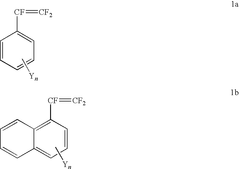
wherein Y is selected from the group consisting of —RFSO2F (sulfonyl fluoride), —RFSO3M (fluorosulfonic acid or salt), —RFSO2NH2 (fluorosulfonamide), and —RFSO2N(M)SO2R2 F (imide); wherein M is H, an alkali cation, or ammonium; and RF and R2 F groups are perfluorinated or partially fluorinated, and may optionally include ether oxygens; and
-
- n is between 1 and 2 for 1a, or n is between 1 and 3 for 1b.

wherein X is hydrogen, halogen, alkyl, or perfluoroalkyl that may include oxygen.
-
- (a) forming a monomer composition comprising a grafting monomer, in neat form, emulsion form, or solution form; wherein the grafting monomer is selected from the group consisting of structure 1a, structure 1b and mixtures thereof:

wherein Y is selected from the group consisting of —RFSO2F (sulfonyl fluoride), —RFSO3M (fluorosulfonic acid or salt), —RFSO2NH2 (fluorosulfonamide), and —RFSO2N(M)SO2R2 F (imide); wherein M is H, an alkali cation, or ammonium; and RF and R2 F groups are perfluorinated or partially fluorinated, and may optionally include ether oxygens; and
-
- n is between 1 and 2 for 1a, or n is between 1 and 3 for 1b;
- (b) irradiating a base polymer with ionizing radiation; and
- (c) contacting the base polymer with the monomer composition from step (a), at a temperature of about 0° C. to about 120° C. for about 0.1 to about 500 hrs. The steps (b) and (c) may be performed simultaneously or sequentially.

wherein X is hydrogen, halogen, alkyl, or perfluoroalkyl that may include oxygen.

wherein Y is selected from the group consisting of —RFSO2F (sulfonyl fluoride), —RFSO3M (fluorosulfonic acid or salt), —RFSO2NH2 (fluorosulfonamide), and —RFSO2N(M)SO2R2 F (imide); wherein M is H, an alkali cation, or ammonium; and RF and R2 F groups are perfluorinated or partially fluorinated, and may optionally include ether oxygens; and
-
- n is between 1 and 2 for 1a, or n is between 1 and 3 for 1b.

wherein X is hydrogen, halogen, alkyl, or perfluoroalkyl that may include oxygen.

wherein Y is —RFSO2F (sulfonyl fluoride), —RFSO3M (fluorosulfonic acid or salt), —RFSO2NH2 (fluorosulfonamide), or —RFSO2N(M)SO2R2 F (imide); wherein M is H, an alkali cation, or ammonium; and RF and R2 F groups are perfluorinated or partially fluorinated alkylene, and may optionally include ether oxygens; and n is between 1 and 2 for 1a, or n is between 1 and 3 for 1b. Some suitable perfluorinated alkylene groups RF, that may optionally include ether oxygens are selected from the group consisting of (CF2)q wherein q=1 to 20, (CF2)qOCF2CF2 wherein q=0 to 12, and (CF2CF(CF3)O)qCF2CF2 wherein q=1 to 8. Typically RF is selected from the group consisting of (CF2)q wherein q=1 to 4; (CF2)qOCF2CF2 wherein q=0 to 6; and (CF2CF(CF3)O)qCF2CF2 wherein q=1 to 2. R2 F groups typically are selected from methyl, ethyl, propyl, butyl, and phenyl, each of which may be partially fluorinated or perfluorinated. More typically R2 F groups are selected from the group consisting of perfluoromethyl, perfluoroethyl, and perfluorophenyl.

The sulfonyl fluoride groups may be converted to acid, metal salt, amide, or imide form, either before the grafting reaction or subsequent to the grafting reaction.
Synthesis of Monomers:

Co-Monomers:

wherein X is hydrogen, halogen, alkyl, or perfluoroalkyl that may include oxygen. Some suitable substituents X are hydrogen, halogen such as Cl, Br, F or I; linear or branched perfluoroalkyl groups, wherein the alkyl group comprises C1 to C10 carbon atoms; or a perfluoroalkyl group containing oxygen, chlorine or bromine, and wherein the perfluoroalkyl group comprises C1 to C10 carbon atoms. More typically, substituents X are selected from the group consisting of hydrogen, chlorine, fluorine, methyl, ethyl, methoxy, perfluoromethyl, perfluoroethyl, perfluorobutyl, perfluoromethoxy, and —CF2CF(CF3)OCF2CF3.
Base Polymer:
-
- (a) forming a monomer composition comprising monomers having structures 1a or 1b, along with optional co-monomers, in neat form, emulsion form, or solution form
- (b) irradiating a base polymer, typically in film form, with ionizing radiation
- (c) contacting the base polymer with the monomer composition from step (a), at a temperature of about 0° C. to about 120° C. for about 0.1 to about 500 hrs. The steps (b) and (c) may be performed simultaneously or sequentially.
κ=1.00 cm/(R×t×w),
where t was the thickness of the membrane and w was its width (both in cm).
| Thickness | |||||
| Initial | after | Wt | |||
| thickness | grafting | uptake | |||
| Film | (um) | (um) | (%) | ||
| PVdF | 62 | 72 | 145 | ||
| ETFE | 27 | 39 | 257 | ||
| ETFE | 65 | 82 | 284 | ||
| RH % | Conductivity (mS/cm) | ||
| 25 | 31 | ||
| 50 | 111 | ||
| 95 | 511 | ||
| Init. | Final | Wt | ||||
| Time | Weight | Weight | uptake | |||
| Film | (h) | (g) | (g) | (%) | ||
| PVdF (1 mil) | 24 | 0.106 | 0.215 | 102.8 | ||
| PVdF (1 mil) | 48 | 0.111 | 0.225 | 102.7 | ||
| PVdF (1 mil) | 72 | 0.103 | 0.213 | 106.8 | ||
| ETFE (2 mil) | 24 | 0.200 | 0.393 | 96.5 | ||
| ETFE (2 mil) | 48 | 0.225 | 0.454 | 101.8 | ||
| ETFE (2 mil) | 72 | 0.216 | 0.450 | 108.3 | ||
| Init. | Final | Wt | ||||
| Time | Weight | Weight | uptake | |||
| Film | (h) | (g) | (g) | (%) | ||
| ETFE (2 mil) | 24 | 0.237 | 0.279 | 23.2 | ||
| ETFE (2 mil) | 48 | 0.211 | 0.311 | 50.2 | ||
| Init. | Final | Wt | ||||
| Time | Weight | Weight | uptake | |||
| Film | (h) | (g) | (g) | (%) | ||
| ETFE (1 mil) | 8 | 0.097 | 0.234 | 141.2 | ||
| ETFE (1 mil) | 24 | 0.116 | 0.477 | 311.2 | ||
| ETFE (1 mil) | 48 | 0.106 | 0.539 | 408.5 | ||
| ETFE (1 mil) | 72 | 0.102 | 0.520 | 409.8 | ||
| ETFE (1 mil) | 72 | 0.465 | 0.2.333 | 401.7 | ||
| Init. | Final | Wt | ||||
| Time | Weight | Weight | uptake | |||
| Film | (h) | (g) | (g) | (%) | ||
| ETFE (2 mil) | 3 | 0.197 | 0.211 | 7.1 | ||
| ETFE (2 mil) | 11 | 0.244 | 0.300 | 22.9 | ||
| ETFE (2 mil) | 30 | 0.212 | 0.322 | 51.9 | ||
| ETFE (2 mil) | 55 | 0.199 | 0.555 | 178.8 | ||
| ETFE (2 mil) | 120 | 0.897 | 3.172 | 253.6 | ||
| RH % | Conductivity (mS/cm) | ||
| 25 | 17.7 | ||
| 50 | 69.8 | ||
| 95 | 368.3 | ||
| RH % | Conductivity (mS/cm) | ||
| 25 | 0.55 | ||
| 50 | 3.95 | ||
| 95 | 43.5 | ||
Claims (40)


Priority Applications (1)
| Application Number | Priority Date | Filing Date | Title |
|---|---|---|---|
| US10/570,024 US7563532B2 (en) | 2003-09-29 | 2004-06-25 | Trifluorostyrene containing compounds, and their use in polymer electrolyte membranes |
Applications Claiming Priority (3)
| Application Number | Priority Date | Filing Date | Title |
|---|---|---|---|
| US50703503P | 2003-09-29 | 2003-09-29 | |
| PCT/US2004/020704 WO2005049204A2 (en) | 2003-09-29 | 2004-06-25 | Trifluorostyrene containing compounds grafted to base polymers |
| US10/570,024 US7563532B2 (en) | 2003-09-29 | 2004-06-25 | Trifluorostyrene containing compounds, and their use in polymer electrolyte membranes |
Publications (2)
| Publication Number | Publication Date |
|---|---|
| US20080206624A1 US20080206624A1 (en) | 2008-08-28 |
| US7563532B2 true US7563532B2 (en) | 2009-07-21 |
Family
ID=34619304
Family Applications (1)
| Application Number | Title | Priority Date | Filing Date |
|---|---|---|---|
| US10/570,024 Expired - Fee Related US7563532B2 (en) | 2003-09-29 | 2004-06-25 | Trifluorostyrene containing compounds, and their use in polymer electrolyte membranes |
Country Status (5)
| Country | Link |
|---|---|
| US (1) | US7563532B2 (en) |
| JP (1) | JP2007507560A (en) |
| DE (1) | DE112004001818T5 (en) |
| TW (1) | TW200512220A (en) |
| WO (1) | WO2005049204A2 (en) |
Cited By (2)
| Publication number | Priority date | Publication date | Assignee | Title |
|---|---|---|---|---|
| US20070208092A1 (en) * | 2004-05-07 | 2007-09-06 | Zhen-Yu Yang | Stable Trifluorostyrene Containing Compounds Grafted To Base Polymers, And Their Use As Polymer Electrolyte Membranes |
| US20080032184A1 (en) * | 2004-05-07 | 2008-02-07 | Zhen-Yu Yang | Stable Trifluorostyrene Containing Compounds, And Their Use In Polymer Electroyte Membranes |
Families Citing this family (6)
| Publication number | Priority date | Publication date | Assignee | Title |
|---|---|---|---|---|
| US7737190B2 (en) | 2005-03-24 | 2010-06-15 | E.I. Du Pont De Nemours And Company | Process to prepare stable trifluorostyrene containing compounds grafted to base polymers using a solvent/water mixture |
| WO2006102670A1 (en) * | 2005-03-24 | 2006-09-28 | E. I. Du Pont De Nemours And Company | Process to prepare stable trifluorostyrene containing compounds grafted to base polymers |
| US20060276556A1 (en) * | 2005-03-24 | 2006-12-07 | Roelofs Mark G | Process to prepare stable trifluorostyrene containing compounds grafted to base polymers using an alcohol/water mixture |
| JP2006351244A (en) * | 2005-06-13 | 2006-12-28 | Shin Etsu Chem Co Ltd | Solid polyelectrolyte membrane, manufacturing method therefor, and fuel cell |
| CA2784539C (en) * | 2009-12-15 | 2015-06-30 | Shandong Huaxia Shenzhou New Material Co., Ltd | High exchange capacity perfluorinated ion exchange resin, preparation method and use thereof |
| US11103833B2 (en) | 2016-03-18 | 2021-08-31 | Entegris, Inc. | Hydrophobic polyethylene membrane for use in venting, degassing, and membrane distillation processes |
Citations (22)
| Publication number | Priority date | Publication date | Assignee | Title |
|---|---|---|---|---|
| US4113922A (en) | 1974-12-23 | 1978-09-12 | Hooker Chemicals & Plastics Corp. | Trifluorostyrene sulfonic acid membranes |
| US4169023A (en) | 1974-02-04 | 1979-09-25 | Tokuyama Soda Kabushiki Kaisha | Electrolytic diaphragms, and method of electrolysis using the same |
| US4384941A (en) | 1981-02-06 | 1983-05-24 | Japan Atomic Energy Research Institute | Process for electrolyzing water |
| US4396727A (en) | 1980-11-17 | 1983-08-02 | Japan Atomic Energy Research Institute | Cation exchange membrane and process for producing the same |
| US4481306A (en) | 1981-08-07 | 1984-11-06 | Ici Australia Limited | Polymerization process |
| US5536754A (en) | 1995-02-15 | 1996-07-16 | E. I. Du Pont De Nemours And Company | Fluorinated ion-exchange polymers and intermediates therefor |
| US5876571A (en) * | 1996-05-10 | 1999-03-02 | E. I. Du Pont De Nemours And Company | Process for making cation exchange membranes with enhanced electrochemical properties |
| US6194474B1 (en) * | 1998-04-18 | 2001-02-27 | Universtitat Stuttgart | Acid-base polymer blends and their application in membrane processes |
| WO2001058576A1 (en) | 2000-02-14 | 2001-08-16 | Ballard Power Systems Inc. | Graft polymeric membranes and ion-exchange membranes formed therefrom |
| US6359019B1 (en) | 1997-11-12 | 2002-03-19 | Ballard Power Systems Inc. | Graft polymeric membranes and ion-exchange membranes formed therefrom |
| US6437011B2 (en) * | 1993-09-21 | 2002-08-20 | Ballard Power Systems Inc. | α,β, β-trifluorostyrene-based composite membranes |
| US20020137806A1 (en) | 1997-11-12 | 2002-09-26 | Charles Stone | Graft polymeric membranes and ion-exchange membranes formed therefrom |
| WO2003006515A1 (en) | 2001-07-13 | 2003-01-23 | E.I. Du Pont De Nemours And Company | Functional fluorine-containing polymers and ionomers derived therefrom |
| WO2003018654A1 (en) | 2001-08-27 | 2003-03-06 | Ballard Power Systems Inc. | Process for preparing graft copolymer membranes |
| WO2004026929A1 (en) | 2002-09-20 | 2004-04-01 | Ballard Power Systems Inc. | Process for preparing graft copolymers useful in membranes |
| WO2005003083A1 (en) | 2003-06-27 | 2005-01-13 | E.I. Dupont De Nemours And Company | Trifluorostyrene containing compounds, and their use in polymer electrolyte membranes |
| WO2005113621A1 (en) | 2004-05-07 | 2005-12-01 | E.I. Dupont De Nemours And Company | Stable trifluorostyrene containing compounds grafted to base polymers |
| WO2005113491A1 (en) | 2004-05-07 | 2005-12-01 | E.I. Dupont De Nemours And Company | Stable trifluorostyrene containing compounds, and their use in polymer electrolyte membranes |
| WO2006102670A1 (en) | 2005-03-24 | 2006-09-28 | E. I. Du Pont De Nemours And Company | Process to prepare stable trifluorostyrene containing compounds grafted to base polymers |
| WO2006102671A1 (en) | 2005-03-24 | 2006-09-28 | E. I. Du Pont De Nemours And Company | Process to prepare stable trifluorostyrene containing compounds grafted to base polymers using a solvent/water mixture |
| WO2006102672A1 (en) | 2005-03-24 | 2006-09-28 | E. I. Du Pont De Nemours And Company | Process to prepare stable trifluorostyrene containing compounds grafted to base polymers using an alcohol/water mixture |
| US7179560B2 (en) * | 2003-02-08 | 2007-02-20 | Samsung Sdi Co., Ltd. | Composite electrolyte membrane and fuel cell containing the same |
Family Cites Families (1)
| Publication number | Priority date | Publication date | Assignee | Title |
|---|---|---|---|---|
| US5602185A (en) * | 1993-09-21 | 1997-02-11 | Ballard Power Systems Inc. | Substituted trifluorostyrene compositions |
-
2004
- 2004-06-25 JP JP2006527966A patent/JP2007507560A/en active Pending
- 2004-06-25 US US10/570,024 patent/US7563532B2/en not_active Expired - Fee Related
- 2004-06-25 TW TW093118621A patent/TW200512220A/en unknown
- 2004-06-25 WO PCT/US2004/020704 patent/WO2005049204A2/en active Application Filing
- 2004-06-25 DE DE112004001818T patent/DE112004001818T5/en not_active Withdrawn
Patent Citations (26)
| Publication number | Priority date | Publication date | Assignee | Title |
|---|---|---|---|---|
| US4169023A (en) | 1974-02-04 | 1979-09-25 | Tokuyama Soda Kabushiki Kaisha | Electrolytic diaphragms, and method of electrolysis using the same |
| US4113922A (en) | 1974-12-23 | 1978-09-12 | Hooker Chemicals & Plastics Corp. | Trifluorostyrene sulfonic acid membranes |
| US4396727A (en) | 1980-11-17 | 1983-08-02 | Japan Atomic Energy Research Institute | Cation exchange membrane and process for producing the same |
| US4384941A (en) | 1981-02-06 | 1983-05-24 | Japan Atomic Energy Research Institute | Process for electrolyzing water |
| US4481306A (en) | 1981-08-07 | 1984-11-06 | Ici Australia Limited | Polymerization process |
| US6437011B2 (en) * | 1993-09-21 | 2002-08-20 | Ballard Power Systems Inc. | α,β, β-trifluorostyrene-based composite membranes |
| US5536754A (en) | 1995-02-15 | 1996-07-16 | E. I. Du Pont De Nemours And Company | Fluorinated ion-exchange polymers and intermediates therefor |
| US5876571A (en) * | 1996-05-10 | 1999-03-02 | E. I. Du Pont De Nemours And Company | Process for making cation exchange membranes with enhanced electrochemical properties |
| US6359019B1 (en) | 1997-11-12 | 2002-03-19 | Ballard Power Systems Inc. | Graft polymeric membranes and ion-exchange membranes formed therefrom |
| US20020137806A1 (en) | 1997-11-12 | 2002-09-26 | Charles Stone | Graft polymeric membranes and ion-exchange membranes formed therefrom |
| US6194474B1 (en) * | 1998-04-18 | 2001-02-27 | Universtitat Stuttgart | Acid-base polymer blends and their application in membrane processes |
| WO2001058576A1 (en) | 2000-02-14 | 2001-08-16 | Ballard Power Systems Inc. | Graft polymeric membranes and ion-exchange membranes formed therefrom |
| WO2003006515A1 (en) | 2001-07-13 | 2003-01-23 | E.I. Du Pont De Nemours And Company | Functional fluorine-containing polymers and ionomers derived therefrom |
| WO2003018654A1 (en) | 2001-08-27 | 2003-03-06 | Ballard Power Systems Inc. | Process for preparing graft copolymer membranes |
| WO2004026929A1 (en) | 2002-09-20 | 2004-04-01 | Ballard Power Systems Inc. | Process for preparing graft copolymers useful in membranes |
| US7179560B2 (en) * | 2003-02-08 | 2007-02-20 | Samsung Sdi Co., Ltd. | Composite electrolyte membrane and fuel cell containing the same |
| WO2005003083A1 (en) | 2003-06-27 | 2005-01-13 | E.I. Dupont De Nemours And Company | Trifluorostyrene containing compounds, and their use in polymer electrolyte membranes |
| US20060135715A1 (en) | 2003-06-27 | 2006-06-22 | Zhen-Yu Yang | Trifluorostyrene containing compounds, and their use in polymer electrolyte membranes |
| WO2005113621A1 (en) | 2004-05-07 | 2005-12-01 | E.I. Dupont De Nemours And Company | Stable trifluorostyrene containing compounds grafted to base polymers |
| WO2005113491A1 (en) | 2004-05-07 | 2005-12-01 | E.I. Dupont De Nemours And Company | Stable trifluorostyrene containing compounds, and their use in polymer electrolyte membranes |
| US20080032184A1 (en) | 2004-05-07 | 2008-02-07 | Zhen-Yu Yang | Stable Trifluorostyrene Containing Compounds, And Their Use In Polymer Electroyte Membranes |
| WO2006102670A1 (en) | 2005-03-24 | 2006-09-28 | E. I. Du Pont De Nemours And Company | Process to prepare stable trifluorostyrene containing compounds grafted to base polymers |
| US20060264576A1 (en) | 2005-03-24 | 2006-11-23 | Roelofs Mark G | Process to prepare stable trifluorostyrene containing compounds grafted to base polymers |
| US20060276555A1 (en) | 2005-03-24 | 2006-12-07 | Roelofs Mark G | Process to prepare stable trifluorostyrene containing compounds grafted to base polymers using a solvent/water mixture |
| WO2006102672A1 (en) | 2005-03-24 | 2006-09-28 | E. I. Du Pont De Nemours And Company | Process to prepare stable trifluorostyrene containing compounds grafted to base polymers using an alcohol/water mixture |
| WO2006102671A1 (en) | 2005-03-24 | 2006-09-28 | E. I. Du Pont De Nemours And Company | Process to prepare stable trifluorostyrene containing compounds grafted to base polymers using a solvent/water mixture |
Non-Patent Citations (1)
| Title |
|---|
| Burton et. al., Palladium-Catalyzed Cross-Coupling of Perfluoroalkenylzince Reagents With Aryl Iodides. J. Org. Chem., 1988, vol. 53:2714-2720. |
Cited By (3)
| Publication number | Priority date | Publication date | Assignee | Title |
|---|---|---|---|---|
| US20070208092A1 (en) * | 2004-05-07 | 2007-09-06 | Zhen-Yu Yang | Stable Trifluorostyrene Containing Compounds Grafted To Base Polymers, And Their Use As Polymer Electrolyte Membranes |
| US20080032184A1 (en) * | 2004-05-07 | 2008-02-07 | Zhen-Yu Yang | Stable Trifluorostyrene Containing Compounds, And Their Use In Polymer Electroyte Membranes |
| US7829603B2 (en) * | 2004-05-07 | 2010-11-09 | E.I. Du Pont De Nemours And Company | Stable trifluorostyrene containing compounds grafted to base polymers, and their use as polymer electrolyte membranes |
Also Published As
| Publication number | Publication date |
|---|---|
| DE112004001818T5 (en) | 2006-09-07 |
| JP2007507560A (en) | 2007-03-29 |
| WO2005049204A3 (en) | 2005-12-15 |
| TW200512220A (en) | 2005-04-01 |
| US20080206624A1 (en) | 2008-08-28 |
| WO2005049204A2 (en) | 2005-06-02 |
Similar Documents
| Publication | Publication Date | Title |
|---|---|---|
| US20060264576A1 (en) | Process to prepare stable trifluorostyrene containing compounds grafted to base polymers | |
| US7265162B2 (en) | Bromine, chlorine or iodine functional polymer electrolytes crosslinked by e-beam | |
| US9419300B2 (en) | Proton conducting materials | |
| US20040241518A1 (en) | Solid polymer membrane for fuel cell prepared by in situ polymerization | |
| US7737190B2 (en) | Process to prepare stable trifluorostyrene containing compounds grafted to base polymers using a solvent/water mixture | |
| US20060135715A1 (en) | Trifluorostyrene containing compounds, and their use in polymer electrolyte membranes | |
| JP2007513471A (en) | Reinforced polymer electrolyte membrane | |
| JP2014500392A (en) | Ionomer and ion conductive composition | |
| US20100093878A1 (en) | Crosslinkable fluoropolymer, crosslinked fluoropolymers and crosslinked fluoropolymer membranes | |
| US20060276556A1 (en) | Process to prepare stable trifluorostyrene containing compounds grafted to base polymers using an alcohol/water mixture | |
| US8071254B2 (en) | Crosslinkable fluoropolymer, crosslinked fluoropolymers and crosslinked fluoropolymer membranes | |
| US7829603B2 (en) | Stable trifluorostyrene containing compounds grafted to base polymers, and their use as polymer electrolyte membranes | |
| US7563532B2 (en) | Trifluorostyrene containing compounds, and their use in polymer electrolyte membranes | |
| US20080032184A1 (en) | Stable Trifluorostyrene Containing Compounds, And Their Use In Polymer Electroyte Membranes | |
| US7456314B2 (en) | Partially fluorinated ionic compounds | |
| JP2007507560A5 (en) | ||
| US8415070B2 (en) | Partially fluorinated cyclic ionic polymers and membranes | |
| CN117397071A (en) | Proton exchange membrane |
Legal Events
| Date | Code | Title | Description |
|---|---|---|---|
| AS | Assignment |
Owner name: E. I. DU PONT DE NEMOURS AND COMPANY, DELAWARE Free format text: ASSIGNMENT OF ASSIGNORS INTEREST;ASSIGNORS:YANG, ZHEN-YU;CHOUDHURY, BISWAJIT;ROELOFS, MARK GERRIT;REEL/FRAME:017666/0865 Effective date: 20050513 Owner name: E. I. DU PONT DE NEMOURS AND COMPANY,DELAWARE Free format text: ASSIGNMENT OF ASSIGNORS INTEREST;ASSIGNORS:YANG, ZHEN-YU;CHOUDHURY, BISWAJIT;ROELOFS, MARK GERRIT;REEL/FRAME:017666/0865 Effective date: 20050513 |
|
| AS | Assignment |
Owner name: E.I. DUPONT DE NEMOURS & CO., INC., DELAWARE Free format text: CONFIRMATORY LICENSE;ASSIGNOR:E.I. DUPONT DE NEMOURS & CO., INC.;REEL/FRAME:028333/0315 Effective date: 20111102 |
|
| AS | Assignment |
Owner name: U.S. DEPARTMENT OF ENERGY, DISTRICT OF COLUMBIA Free format text: CONFIRMATORY LICENSE;ASSIGNOR:E.I. DUPONT DE NEMOURS & CO., INC.;REEL/FRAME:028373/0468 Effective date: 20111102 |
|
| FPAY | Fee payment |
Year of fee payment: 4 |
|
| REMI | Maintenance fee reminder mailed | ||
| LAPS | Lapse for failure to pay maintenance fees |
Free format text: PATENT EXPIRED FOR FAILURE TO PAY MAINTENANCE FEES (ORIGINAL EVENT CODE: EXP.) |
|
| STCH | Information on status: patent discontinuation |
Free format text: PATENT EXPIRED DUE TO NONPAYMENT OF MAINTENANCE FEES UNDER 37 CFR 1.362 |
|
| FP | Lapsed due to failure to pay maintenance fee |
Effective date: 20170721 |