US7570464B2 - Overload protective apparatus of a compressor and a method thereof - Google Patents
Overload protective apparatus of a compressor and a method thereof Download PDFInfo
- Publication number
- US7570464B2 US7570464B2 US10/498,099 US49809904A US7570464B2 US 7570464 B2 US7570464 B2 US 7570464B2 US 49809904 A US49809904 A US 49809904A US 7570464 B2 US7570464 B2 US 7570464B2
- Authority
- US
- United States
- Prior art keywords
- compressor
- power supply
- power
- unit
- current value
- Prior art date
- Legal status (The legal status is an assumption and is not a legal conclusion. Google has not performed a legal analysis and makes no representation as to the accuracy of the status listed.)
- Expired - Fee Related
Links
Images


Classifications
-
- F—MECHANICAL ENGINEERING; LIGHTING; HEATING; WEAPONS; BLASTING
- F04—POSITIVE - DISPLACEMENT MACHINES FOR LIQUIDS; PUMPS FOR LIQUIDS OR ELASTIC FLUIDS
- F04B—POSITIVE-DISPLACEMENT MACHINES FOR LIQUIDS; PUMPS
- F04B49/00—Control, e.g. of pump delivery, or pump pressure of, or safety measures for, machines, pumps, or pumping installations, not otherwise provided for, or of interest apart from, groups F04B1/00 - F04B47/00
- F04B49/06—Control using electricity
- F04B49/065—Control using electricity and making use of computers
-
- F—MECHANICAL ENGINEERING; LIGHTING; HEATING; WEAPONS; BLASTING
- F04—POSITIVE - DISPLACEMENT MACHINES FOR LIQUIDS; PUMPS FOR LIQUIDS OR ELASTIC FLUIDS
- F04B—POSITIVE-DISPLACEMENT MACHINES FOR LIQUIDS; PUMPS
- F04B35/00—Piston pumps specially adapted for elastic fluids and characterised by the driving means to their working members, or by combination with, or adaptation to, specific driving engines or motors, not otherwise provided for
- F04B35/04—Piston pumps specially adapted for elastic fluids and characterised by the driving means to their working members, or by combination with, or adaptation to, specific driving engines or motors, not otherwise provided for the means being electric
- F04B35/045—Piston pumps specially adapted for elastic fluids and characterised by the driving means to their working members, or by combination with, or adaptation to, specific driving engines or motors, not otherwise provided for the means being electric using solenoids
-
- F—MECHANICAL ENGINEERING; LIGHTING; HEATING; WEAPONS; BLASTING
- F04—POSITIVE - DISPLACEMENT MACHINES FOR LIQUIDS; PUMPS FOR LIQUIDS OR ELASTIC FLUIDS
- F04B—POSITIVE-DISPLACEMENT MACHINES FOR LIQUIDS; PUMPS
- F04B49/00—Control, e.g. of pump delivery, or pump pressure of, or safety measures for, machines, pumps, or pumping installations, not otherwise provided for, or of interest apart from, groups F04B1/00 - F04B47/00
- F04B49/02—Stopping, starting, unloading or idling control
-
- H—ELECTRICITY
- H02—GENERATION; CONVERSION OR DISTRIBUTION OF ELECTRIC POWER
- H02P—CONTROL OR REGULATION OF ELECTRIC MOTORS, ELECTRIC GENERATORS OR DYNAMO-ELECTRIC CONVERTERS; CONTROLLING TRANSFORMERS, REACTORS OR CHOKE COILS
- H02P25/00—Arrangements or methods for the control of AC motors characterised by the kind of AC motor or by structural details
- H02P25/02—Arrangements or methods for the control of AC motors characterised by the kind of AC motor or by structural details characterised by the kind of motor
- H02P25/032—Reciprocating, oscillating or vibrating motors
-
- F—MECHANICAL ENGINEERING; LIGHTING; HEATING; WEAPONS; BLASTING
- F04—POSITIVE - DISPLACEMENT MACHINES FOR LIQUIDS; PUMPS FOR LIQUIDS OR ELASTIC FLUIDS
- F04B—POSITIVE-DISPLACEMENT MACHINES FOR LIQUIDS; PUMPS
- F04B2201/00—Pump parameters
- F04B2201/02—Piston parameters
- F04B2201/0206—Length of piston stroke
-
- F—MECHANICAL ENGINEERING; LIGHTING; HEATING; WEAPONS; BLASTING
- F04—POSITIVE - DISPLACEMENT MACHINES FOR LIQUIDS; PUMPS FOR LIQUIDS OR ELASTIC FLUIDS
- F04B—POSITIVE-DISPLACEMENT MACHINES FOR LIQUIDS; PUMPS
- F04B2203/00—Motor parameters
- F04B2203/04—Motor parameters of linear electric motors
- F04B2203/0401—Current
-
- F—MECHANICAL ENGINEERING; LIGHTING; HEATING; WEAPONS; BLASTING
- F04—POSITIVE - DISPLACEMENT MACHINES FOR LIQUIDS; PUMPS FOR LIQUIDS OR ELASTIC FLUIDS
- F04B—POSITIVE-DISPLACEMENT MACHINES FOR LIQUIDS; PUMPS
- F04B2203/00—Motor parameters
- F04B2203/04—Motor parameters of linear electric motors
- F04B2203/0402—Voltage
Definitions
- the present invention relates to a compressor, and particularly, to an overload protective apparatus of a compressor and its method capable of preventing a compressor for being damaged by overload without using an over load protector (OLP).
- OHP over load protector
- a compressor particularly, a reciprocating compressor has no crankshaft for converting a rotating movement to a linear movement, thereby having small friction loss and so having higher efficiency in compression than that of a general compressor.
- the reciprocating compressor is used for a refrigerator or an air conditioner
- a stroke voltage inputted to the reciprocating compressor is varied
- a compression ratio of the reciprocating compressor can be varied to control freezing compressor.
- FIG. 1 is a block diagram showing a structure of an operation control device of the reciprocating compressor in accordance with the conventional art.
- the operation control device of the reciprocating compressor includes: a voltage detecting unit 14 for detecting a voltage applied to the reciprocating compressor 13 as the compressor operates; a current detecting unit 12 for detecting a current applied to the reciprocating compressor 13 as the compressor operates; a microcomputer 15 for calculating a stroke by using the voltage detected by the voltage detecting unit 14 and the current detected by the current detecting unit 12 , comparing the calculated stroke and a stroke reference value, and outputting a switching control signal on the basis of the comparison result; and a power supply unit 11 for supplying a stroke voltage to the reciprocating compressor 13 by on-off controlling AC power supplied to the reciprocating compressor 13 according to the switching control signal outputted from the microcomputer 15 by using an internal triac (Tr 1 ).
- the reciprocating compressor 13 receives a stroke voltage provided to an internal motor (not shown) according to a stroke reference value set by a user and varies an internal stroke so as to vertically move a piston (not shown) in the compressor.
- the reciprocating motor compressor 13 receives a voltage supplied to the motor on the basis of the stroke reference value set by a user and varies the stroke so as to vertically move the stroke.
- the stroke means a moving distance of a piston in the reciprocating motor compressor 13 in a reciprocating movement.
- a turn-on period of the triac (Tr 1 ) of the power supply unit 11 is lengthened by a switching control signal outputted from the microcomputer 15 .
- the AC power is supplied to the reciprocating motor compressor 13 to drive the reciprocating motor compressor 13 .
- the voltage detecting unit 14 and the current detecting unit 12 detect a voltage and a current applied to the reciprocating motor compressor 13 and output the detected voltage and current to the microcomputer 15 , respectively.
- the microcomputer 15 calculates a stroke by using the voltage and the current detected by the voltage detecting unit 14 and the current detecting unit 12 , then, compares the calculated stroke with the stroke reference value, and outputs a switching control signal according to the comparison result. That is, when the calculated stroke is smaller than the stroke reference value, the microcomputer 15 outputs a switching control signal for lengthening an on-period of the triac (Tr 1 ) to the power supply unit 11 thereby increasing a stroke voltage supplied to the reciprocating motor compressor 13 .
- the microcomputer 15 when the calculated stroke is greater than the stroke reference value, the microcomputer 15 outputs a switching control signal for shortening an on-period of the triac (Tr 1 ) to the power supply unit 11 thereby decreasing a stroke voltage supplied to the reciprocating motor compressor 13 .
- an over load protector (OLP) 20 for cutting off power applied to. a motor of the compressor 13 when a temperature of the compressor 13 is high or when over current flows in a internal motor of the compressor 13 is installed independent of the operation control device.
- OTP over load protector
- the over load protector 20 detects a temperature of a compressor 13 electrically connected with itself. In addition, the over load protector 20 detects heat due to a current flowing therein, and cuts off or passes power applied to an internal motor of the compressor 13 on the basis of a temperature of the detected heat. That is, when a temperature of the compressor 13 gets high, or over current flows in the internal motor of the compressor 13 , the over load protector 20 operates to cut off power supplied to the compressor 13 , and thus prevents damage of the compressor 13 .
- the over load protector installed in the compressor 13 in accordance with the conventional art cannot be minimized by a size of a power device (not shown) in the over load protector 20 , and also, a cost for the compressor increases by installing the over load protector in the compressor.
- an object of the present invention to provide an overload protective apparatus and its method capable of preventing damage of a compressor due to overload by using an operation control device operating the compressor without using the overload protector.
- an overload protective apparatus of a compressor including: a reference current setting unit for presetting a reference current value for normally operating a compressor; a current detecting unit for detecting a current applied to the compressor; a microcomputer for generating a power cutoff signal when the detected current value is greater than the reference current value, and for generating a power supply signal when the detected current value is smaller than the reference current value; and a power supply unit for cutting off power applied to the compressor on the basis of the power cutoff signal, or for applying power to the compressor on the basis of the power supply signal.
- an operation control device of a compressor including a voltage detecting unit for detecting a voltage applied to a compressor; a current detecting unit for detecting a current applied to the compressor; a microcomputer for calculating a stroke by using a voltage detected by the voltage detecting unit and a current detected by the current detecting unit, comparing the calculated stroke and a stroke reference value and outputting a switching control signal on the basis of the comparison result; and a power supply unit for supplying a stroke voltage to the compressor by on-off controlling AC power supplied to the compressor on the basis of the switching control signal outputted from the microcomputer by using an internal triac (Tr 1 ), further comprising: a reference current setting unit for presetting a reference current value of the compressor; a microcomputer for generating a power cutoff signal when the detected current value is greater than the reference current value and outputting the generated power cutoff signal or for generating a power supply signal when the detected current value is smaller than the reference current value and outputting the generated power supply signal; and
- a method for protecting a compressor from overload comprising: detecting a current applied to a compressor; comparing the detected current value and a pre-stored reference current value; generating a power cutoff signal when the detected current value is greater than the reference current value, and generating a power supply signal when the detected current value is the same as or smaller than the reference current value; and cutting off power applied to an internal motor of the compressor on the basis of the power cutoff signal or applying power to the internal motor of the compressor on the basis of the power supply signal.
- a method for controlling operation of a compressor including detecting a voltage and a current applied to a compressor; calculating a stroke by using the voltage and the current; comparing the calculated stroke and a stroke reference value; and controlling an operation of the compressor on the basis of the comparison result, further comprising: comparing the detected current value and a pre-stored reference current value; generating a power cutoff signal when the detected current value is greater than the reference current value, and generating a power supply signal when the detected current value is the same as or smaller than the reference current value; and cutting off power applied to an internal motor of the compressor on the basis of the power cutoff signal, or applying power to the internal motor of the compressor on the basis of the power supply signal.
- FIG. 1 is a block diagram showing a structure of an operation control device of a reciprocating compressor in accordance with the conventional art
- FIG. 2 is a block diagram showing a structure of an operation control device and an overload protective apparatus of a reciprocating compressor in accordance with the present invention
- FIG. 3 is a block diagram showing a structure of a different embodiment of an overload protective apparatus of a reciprocating compressor in accordance with the present invention.
- FIG. 4 is a flow chart showing an operational order of an overload protective apparatus of a reciprocating compressor in accordance with a different embodiment of the present invention.
- FIGS. 2 through 4 a preferred embodiment of an overload protective apparatus and its method capable of preventing damage of a compressor due to overload, by using an operation control apparatus for controlling an operation of the compressor, without using an over load protector.
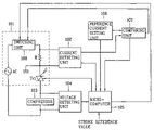
- FIG. 2 is a block diagram showing a structure of an operation control device and an overload protective apparatus of a reciprocating compressor in accordance with the present invention.
- an operation control device of the reciprocating compressor includes: a voltage detecting unit 104 for detecting a voltage applied to the reciprocating compressor 103 as a piston in the reciprocating compressor is driven; a current detecting unit 102 for detecting a current applied to the reciprocating compressor 103 as a piston in the compressor is driven; a microcomputer 105 for calculating a stroke by using the voltage detected by the voltage detecting unit 104 and the current detected by the current detecting unit 102 , comparing the calculated stroke and a stroke reference value, and outputting a switching control signal on the basis of the comparison result; and a power supply unit 101 for supplying a stroke voltage to the reciprocating compressor 103 by turning on/off AC power supplied to the reciprocating compressor 103 according to a switching control signal outputted from the microcomputer 105 by using an internal triac (Tr 1 ).
- the overload protective apparatus in accordance with the present invention includes: the current detecting unit 102 , the microcomputer 105 , the power supply unit 101 and a reference current setting unit 106 for presetting a reference current for normally operating a motor in the compressor.
- the microcomputer 105 when a detected current value is greater than the reference current value, the microcomputer 105 generates a power cutoff signal and outputs the generated power cutoff signal, when the detected current value is smaller than the reference current value, the microcomputer 105 generates a power supply signal and outputs the generated power supply signal.
- the power supply unit 101 cuts off power applied to an internal motor of the compressor 103 on the basis of the power cutoff signal, or applies power to the internal motor of the compressor 103 on the basis of the power supply signal.
- the current detecting unit 102 of the overload protective apparatus detects a current applied to an internal motor of the compressor in real time, and outputs the detected current value to the microcomputer 105 .
- the microcomputer 105 When a current value detected by the current detecting unit 102 is greater than a reference current value preset in the reference current setting unit 106 , the microcomputer 105 generates a power cutoff signal, and outputs the generated power cutoff signal to the power supply unit 101 . But when a current value detected by the current detecting unit 102 is the same as or smaller than a reference current value preset in the reference current setting unit 106 , the microcomputer 105 generates a power supply signal, and outputs the generated power supply signal to the power supply unit 101 .
- the triac (Tr 1 ) of the power supply unit 101 cuts off power applied to an internal motor of the compressor 103 on the basis of the power cutoff signal, or applies power to the internal motor of the compressor 103 on the basis of the power supply signal. That is, the triac (Tr 1 ) of the power supply unit 101 controls a turn-on period on the basis of the power supply signal or the power cutoff signal outputted from the microcomputer 105 , to cut off or pass power applied to the internal motor of the compressor 103 .
- FIG. 3 is a block diagram showing a structure of a different embodiment of an overload protective apparatus of a reciprocating compressor in accordance with the present invention.
- an overload protective apparatus in accordance with the different embodiment of the present invention includes: a reference current setting unit 106 for pre-storing a reference current value; a current detecting unit 102 for detecting a current applied to an internal motor (not shown) of the compressor when the compressor 103 operates; a microcomputer 105 for generating a power cutoff signal when a current value detected by the current detecting unit 102 is greater than the reference current value stored in the reference current setting unit 106 and outputting the generated power cutoff signal, or for generating a power supply signal when the detected current value is the same as or smaller than the reference current value and outputting the generated power supply signal; and switching unit 108 for cutting off power applied to the internal motor of the compressor 103 on the basis of the power cutoff signal, or for applying power to the internal motor of the compressor 103 on the basis of the power supply signal.
- the overload protective apparatus of the reciprocating compressor in accordance with the difference embodiment of the present invention further includes a comparing unit 107 which is driven independent of the microcomputer 105 when the microcomputer 105 does not operate. That is, the comparing unit 107 compares a current value detected by the current detecting unit 102 and a reference current value pre-stored in the reference current setting unit 106 , generates a power cutoff signal when the current value detected by the current detecting unit 102 is greater than the reference current value and outputs the generated power cutoff signal to the switching unit 108 . When the detected current value is smaller than the reference current value, the comparing unit 107 generates a power supply signal and outputs the generated power supply signal to the switching unit 108 .
- the microcomputer 105 receives the power supply signal from the comparing unit 107 and controls a turn-on period of the triac (Tr 1 ) in the power supply unit 101 thereby applying power to the internal motor of the compressor, or the microcomputer 105 receives the power cutoff signal from the comparing unit 107 and controls a turn-on period of the internal triac of the power supply unit 101 thereby cutting off power applied to the internal motor of the compressor 103 .
- the comparing unit 107 if the comparing unit 107 does not operate because of a break down or the like, the power can be cut off or applied by an output signal of the microcomputer 105 . That is, in case that the comparing unit 107 does not operate, the microcomputer 105 generates a power cutoff signal when a current detected by the current detecting unit 102 is greater than a reference current value pre-stored in the reference current setting unit 106 and outputs the generated power cutoff signal to the switching unit 108 . When the detected current value is smaller than the reference current value, the microcomputer 105 generates a power supply signal and outputs the generated power supply signal to the switching unit 108 .
- a device for performing a contact/noncontact type mechanical operation such as a relay (not shown), as the switching unit 108 , in order to apply or cut off power applied to an internal motor of the compressor 103 on the basis of an output signal of the microcomputer 105 or the comparing unit 107 .
- FIG. 4 is a flow chart showing an operational order of an overload protective apparatus of a reciprocating compressor in accordance with the difference embodiment of the present invention.
- the current detecting unit 102 detects a current applied to an internal motor of the compressor 103 when the compressor 103 operates, in real time (S 11 ).
- the microcomputer 105 generates a power cutoff signal when a current value detected by the current detecting unit 102 is greater than a reference current value stored in the reference current setting unit 102 , and outputs the generated power cutoff signal to the switching unit 108 (S 12 ⁇ S 14 ). At this time, the switching unit 108 cuts off power applied to the compressor on the basis of the power cutoff signal. That is, if over current is detected, the microcomputer 105 controls the switching unit 108 such as a relay to cut off power applied to a motor in the compressor 103 (S 15 ).
- the microcomputer 105 generates a power supply signal when the detected current value is the same as or smaller than the reference current value and outputs the generated power supply signal to the switching unit 108 .
- the switching unit 108 applies power to the compressor 103 on the basis of the power supply signal. That is, if over current is not detected, the microcomputer 105 controls the switching unit 108 such as a relay to apply power to the motor in the compressor 103 and normally drives the compressor 103 (S 16 , S 17 ).
- the power can be cut off or applied by an output signal of the comparing unit 107 . That is, the comparing unit 107 compares a reference current value pre-stored in the reference current setting unit 106 and a current value detected by the current detecting unit 102 , generates a power cutoff signal when the current value detected by the current detecting unit 102 is greater than the reference current value, and outputs the generated power cutoff signal to the switching unit 108 (S 12 ⁇ S 14 ). At this time, the switching unit 108 cuts off power applied to the compressor 103 on the basis of the power cutoff signal.
- the comparing unit 107 when the detected current value is the same as or smaller than the reference current value, the comparing unit 107 generates a power supply signal, and outputs the generated power supply signal to the switching unit 108 .
- the switching unit 108 applies power to the compressor on the basis of the switching signal.
- the reference current value is preset by a user and means a current value that should be applied to an internal motor of the compressor 103 in order to normally drive the motor. That is, the reference current value is set in such a manner of measuring a current value applied to an internal motor of the compressor when the compressor normally operates and storing the measured value (S 12 ⁇ S 13 , 16 ).
- the microcomputer 105 determines whether a predetermined time (e.g., 1 ⁇ 3 minutes) elapses after cutting off power applied to the compressor 103 . If the predetermined time elapses, the microcomputer 105 generates the power supply signal, and outputs the generated power supply signal to the switching unit 108 . At this time, the switching unit 108 applies power to the compressor 103 on the basis of the power supply signal so that the compressor 103 can normally operate.
- a predetermined time e.g., 1 ⁇ 3 minutes
- the microcomputer 105 determines whether the predetermined time has not been elapse. If the predetermined time does not elapse, the microcomputer 105 generates the power cutoff signal, and outputs the generated power cutoff signal to the switching unit 108 . At this time, the switching unit 108 cuts off power applied to the compressor 103 on the basis of the power cutoff signal (S 18 ).
- the present invention is advantageous in that damage of a compressor due to the over current can be prevented without using a conventional over load protector (OLP), by comparing a current value applied to an internal motor of a compressor when the compressor operates and the reference current value, and cutting off or applying power to the internal motor of the compressor on the basis of the comparison result.
- OHP over load protector
- the present invention is advantageous in that a cost can be reduced by using an operation control device for controlling an operation of the compressor, without using the conventional over load protector (OLP).
- OHP over load protector
- the present invention is advantageous in that the compressor can be minimized by using an operation control device for controlling an operation of the compressor, without using the conventional over load protector (OLP).
- OHP over load protector
Abstract
Description
Claims (7)
Applications Claiming Priority (1)
| Application Number | Priority Date | Filing Date | Title |
|---|---|---|---|
| PCT/KR2002/001910 WO2004033909A1 (en) | 2002-10-11 | 2002-10-11 | Overload protective apparatus of a compressor and a method thereof |
Publications (2)
| Publication Number | Publication Date |
|---|---|
| US20050083630A1 US20050083630A1 (en) | 2005-04-21 |
| US7570464B2 true US7570464B2 (en) | 2009-08-04 |
Family
ID=32089647
Family Applications (1)
| Application Number | Title | Priority Date | Filing Date |
|---|---|---|---|
| US10/498,099 Expired - Fee Related US7570464B2 (en) | 2002-10-11 | 2002-10-11 | Overload protective apparatus of a compressor and a method thereof |
Country Status (7)
| Country | Link |
|---|---|
| US (1) | US7570464B2 (en) |
| JP (1) | JP4272160B2 (en) |
| CN (1) | CN100390414C (en) |
| AU (1) | AU2002368283A1 (en) |
| BR (1) | BRPI0214773B1 (en) |
| DE (1) | DE10297637B4 (en) |
| WO (1) | WO2004033909A1 (en) |
Cited By (1)
| Publication number | Priority date | Publication date | Assignee | Title |
|---|---|---|---|---|
| JP2014511959A (en) * | 2011-03-15 | 2014-05-19 | ワールプール,ソシエダッド アノニマ | Operating system for resonant linear compressor, operating method of resonant linear compressor and resonant linear compressor |
Families Citing this family (17)
| Publication number | Priority date | Publication date | Assignee | Title |
|---|---|---|---|---|
| KR100494384B1 (en) * | 2002-09-03 | 2005-06-13 | 삼성전자주식회사 | Output control apparatus for linear compressor and control method thereof |
| US20080041081A1 (en) | 2006-08-15 | 2008-02-21 | Bristol Compressors, Inc. | System and method for compressor capacity modulation in a heat pump |
| DE102006009231A1 (en) * | 2006-02-28 | 2007-08-30 | BSH Bosch und Siemens Hausgeräte GmbH | Operation method for linear compressor in cooling equipment involves evaluating amplitude of motion of linear compressor to determine overloaded condition |
| KR100806100B1 (en) * | 2006-04-20 | 2008-02-21 | 엘지전자 주식회사 | Driving control apparatus and method for linear compressor |
| JP4737153B2 (en) * | 2007-06-29 | 2011-07-27 | ダイキン工業株式会社 | AC solenoid valve protection device |
| US8904814B2 (en) * | 2008-06-29 | 2014-12-09 | Bristol Compressors, International Inc. | System and method for detecting a fault condition in a compressor |
| US8601828B2 (en) * | 2009-04-29 | 2013-12-10 | Bristol Compressors International, Inc. | Capacity control systems and methods for a compressor |
| US9168315B1 (en) * | 2011-09-07 | 2015-10-27 | Mainstream Engineering Corporation | Cost-effective remote monitoring, diagnostic and system health prediction system and method for vapor compression and heat pump units based on compressor discharge line temperature sampling |
| CN103904966A (en) * | 2012-12-27 | 2014-07-02 | 苏州宝时得电动工具有限公司 | Electric tool and motor control method of electric tool |
| CN103939321B (en) * | 2014-04-02 | 2016-08-10 | 邯郸美的制冷设备有限公司 | A kind of compressor of air conditioner starts control method and device |
| CN105781953B (en) * | 2014-12-25 | 2018-06-12 | Tcl空调器(中山)有限公司 | Prevent control method, controller and the air conditioner of overload of compressor |
| CN105510696A (en) * | 2015-12-28 | 2016-04-20 | 广东芬尼克兹节能设备有限公司 | Current transformer module and compressor protection control method using same |
| CN106123211A (en) * | 2016-06-22 | 2016-11-16 | 广东美的制冷设备有限公司 | In air-conditioner and air-conditioner, the low-voltage variation of compressor controls apparatus and method |
| CN106026837A (en) * | 2016-07-14 | 2016-10-12 | 哈尔滨兴亚技术有限公司 | Power driver |
| CN107611926B (en) * | 2017-09-15 | 2020-11-06 | 珠海格力电器股份有限公司 | Overload protection device and method, storage medium, compressor and electric appliance |
| CN110173421A (en) * | 2019-04-22 | 2019-08-27 | 广东美博制冷设备有限公司 | A kind of method and device for overload protection of compressor |
| GB2611362A (en) * | 2021-10-04 | 2023-04-05 | Aspen Pumps Ltd | Condensate pump assembly & control methods |
Citations (28)
| Publication number | Priority date | Publication date | Assignee | Title |
|---|---|---|---|---|
| US3721880A (en) * | 1971-10-12 | 1973-03-20 | Carrier Corp | Refrigerant compressor motor control |
| US3742303A (en) * | 1971-11-08 | 1973-06-26 | Bec Prod Inc | Compressor protector system |
| JPS57194858A (en) * | 1981-05-21 | 1982-11-30 | Mitsubishi Electric Corp | Profiling controlling device |
| US4514989A (en) * | 1984-05-14 | 1985-05-07 | Carrier Corporation | Method and control system for protecting an electric motor driven compressor in a refrigeration system |
| DE2429279C2 (en) | 1973-06-20 | 1986-06-12 | Hitachi, Ltd., Tokio/Tokyo | Tax order |
| US4617472A (en) * | 1983-07-19 | 1986-10-14 | Nuvatec, Inc. | Recreational vehicle power control system |
| JPS62103492A (en) | 1985-10-31 | 1987-05-13 | Sawafuji Electric Co Ltd | Device for protecting car-loaded refrigerator from overcurrent |
| JPH01281353A (en) * | 1988-01-07 | 1989-11-13 | Mitsubishi Electric Corp | Protection circuit for air conditioner |
| JPH0328650A (en) * | 1989-06-27 | 1991-02-06 | Mitsubishi Electric Corp | Air conditioner |
| US5182459A (en) * | 1990-02-07 | 1993-01-26 | Zexel Corporation | Control system for vehicle safety device |
| JPH0518588A (en) | 1991-07-12 | 1993-01-26 | Sanyo Electric Co Ltd | Protecting method for overcurrent of air conditioner |
| US5209075A (en) * | 1990-11-20 | 1993-05-11 | Samsung Electronics Co., Ltd. | Current controlling apparatus and method for air conditioning apparatus |
| US5349162A (en) * | 1993-04-05 | 1994-09-20 | Whirlpool Corporation | Fault detection method and apparatus for a domestic appliance |
| DE4333591A1 (en) | 1993-10-01 | 1995-04-06 | Bayerische Motoren Werke Ag | Controller for switching the electric drive motor, in particular of an air compressor, on and off to match the demand |
| US5414989A (en) * | 1990-01-24 | 1995-05-16 | Temco Textilmachinenkomponenten Gmbh & Co. Kg | Three disk set friction false-twisting unit with swung out set of disks |
| JPH07158931A (en) * | 1993-12-08 | 1995-06-20 | Matsushita Seiko Co Ltd | Controller for air-conditioner |
| JPH09112438A (en) | 1995-10-20 | 1997-05-02 | Sanyo Electric Co Ltd | Driver of linear compressor |
| US5631796A (en) * | 1992-09-18 | 1997-05-20 | Hitachi, Ltd. | Electric vehicle control system |
| JPH10122141A (en) | 1996-10-18 | 1998-05-12 | Sanyo Electric Co Ltd | Driving device of linear compressor |
| US5986597A (en) * | 1995-06-12 | 1999-11-16 | Scully Signal Company | Fluid transfer controller with digital bitstream monitor |
| JPH11351143A (en) | 1998-06-10 | 1999-12-21 | Matsushita Electric Ind Co Ltd | Driving device for linear compressor |
| US6158230A (en) * | 1998-03-30 | 2000-12-12 | Sanyo Electric Co., Ltd. | Controller for air conditioner |
| US6176683B1 (en) * | 1999-04-26 | 2001-01-23 | Lg Electronics, Inc. | Output control apparatus for linear compressor and method of the same |
| EP1100190A2 (en) | 1999-11-12 | 2001-05-16 | Lg Electronics Inc. | Device and method for controlling the current supply and the static capacitance of a compressor |
| DE10147610A1 (en) | 2000-09-27 | 2002-06-06 | Lg Electronics Inc | Reciprocating compressor controller for refrigerator, controls voltage supply to drive circuit to make stroke corresponding to detected phase difference inflection point |
| JP2002235673A (en) | 2000-11-29 | 2002-08-23 | Lg Electronics Inc | Operation control device for compressor and control method therefor |
| US6550870B1 (en) * | 2001-08-29 | 2003-04-22 | Robert Bosch Corporation | Parking brake control |
| US20050015125A1 (en) * | 2003-03-14 | 2005-01-20 | Mioduski Paul C. | Hyperthermia treatment systems and methods |
Family Cites Families (4)
| Publication number | Priority date | Publication date | Assignee | Title |
|---|---|---|---|---|
| JPH09294397A (en) * | 1996-04-24 | 1997-11-11 | Mitsubishi Electric Corp | Motor controller for air conditioner |
| JP2001204180A (en) * | 2000-01-20 | 2001-07-27 | Fujitsu General Ltd | Controller for air conditioner |
| JP4505932B2 (en) * | 2000-03-24 | 2010-07-21 | ダイキン工業株式会社 | Air conditioner drive circuit and air conditioner drive method |
| JP4179735B2 (en) * | 2000-07-13 | 2008-11-12 | 三洋電機株式会社 | Compressor operation control method and apparatus for air conditioner and air conditioner |
-
2002
- 2002-10-11 US US10/498,099 patent/US7570464B2/en not_active Expired - Fee Related
- 2002-10-11 CN CNB02827203XA patent/CN100390414C/en not_active Expired - Fee Related
- 2002-10-11 WO PCT/KR2002/001910 patent/WO2004033909A1/en active Application Filing
- 2002-10-11 AU AU2002368283A patent/AU2002368283A1/en not_active Abandoned
- 2002-10-11 JP JP2004542884A patent/JP4272160B2/en not_active Expired - Fee Related
- 2002-10-11 BR BRPI0214773A patent/BRPI0214773B1/en not_active IP Right Cessation
- 2002-10-11 DE DE10297637T patent/DE10297637B4/en not_active Expired - Fee Related
Patent Citations (28)
| Publication number | Priority date | Publication date | Assignee | Title |
|---|---|---|---|---|
| US3721880A (en) * | 1971-10-12 | 1973-03-20 | Carrier Corp | Refrigerant compressor motor control |
| US3742303A (en) * | 1971-11-08 | 1973-06-26 | Bec Prod Inc | Compressor protector system |
| DE2429279C2 (en) | 1973-06-20 | 1986-06-12 | Hitachi, Ltd., Tokio/Tokyo | Tax order |
| JPS57194858A (en) * | 1981-05-21 | 1982-11-30 | Mitsubishi Electric Corp | Profiling controlling device |
| US4617472A (en) * | 1983-07-19 | 1986-10-14 | Nuvatec, Inc. | Recreational vehicle power control system |
| US4514989A (en) * | 1984-05-14 | 1985-05-07 | Carrier Corporation | Method and control system for protecting an electric motor driven compressor in a refrigeration system |
| JPS62103492A (en) | 1985-10-31 | 1987-05-13 | Sawafuji Electric Co Ltd | Device for protecting car-loaded refrigerator from overcurrent |
| JPH01281353A (en) * | 1988-01-07 | 1989-11-13 | Mitsubishi Electric Corp | Protection circuit for air conditioner |
| JPH0328650A (en) * | 1989-06-27 | 1991-02-06 | Mitsubishi Electric Corp | Air conditioner |
| US5414989A (en) * | 1990-01-24 | 1995-05-16 | Temco Textilmachinenkomponenten Gmbh & Co. Kg | Three disk set friction false-twisting unit with swung out set of disks |
| US5182459A (en) * | 1990-02-07 | 1993-01-26 | Zexel Corporation | Control system for vehicle safety device |
| US5209075A (en) * | 1990-11-20 | 1993-05-11 | Samsung Electronics Co., Ltd. | Current controlling apparatus and method for air conditioning apparatus |
| JPH0518588A (en) | 1991-07-12 | 1993-01-26 | Sanyo Electric Co Ltd | Protecting method for overcurrent of air conditioner |
| US5631796A (en) * | 1992-09-18 | 1997-05-20 | Hitachi, Ltd. | Electric vehicle control system |
| US5349162A (en) * | 1993-04-05 | 1994-09-20 | Whirlpool Corporation | Fault detection method and apparatus for a domestic appliance |
| DE4333591A1 (en) | 1993-10-01 | 1995-04-06 | Bayerische Motoren Werke Ag | Controller for switching the electric drive motor, in particular of an air compressor, on and off to match the demand |
| JPH07158931A (en) * | 1993-12-08 | 1995-06-20 | Matsushita Seiko Co Ltd | Controller for air-conditioner |
| US5986597A (en) * | 1995-06-12 | 1999-11-16 | Scully Signal Company | Fluid transfer controller with digital bitstream monitor |
| JPH09112438A (en) | 1995-10-20 | 1997-05-02 | Sanyo Electric Co Ltd | Driver of linear compressor |
| JPH10122141A (en) | 1996-10-18 | 1998-05-12 | Sanyo Electric Co Ltd | Driving device of linear compressor |
| US6158230A (en) * | 1998-03-30 | 2000-12-12 | Sanyo Electric Co., Ltd. | Controller for air conditioner |
| JPH11351143A (en) | 1998-06-10 | 1999-12-21 | Matsushita Electric Ind Co Ltd | Driving device for linear compressor |
| US6176683B1 (en) * | 1999-04-26 | 2001-01-23 | Lg Electronics, Inc. | Output control apparatus for linear compressor and method of the same |
| EP1100190A2 (en) | 1999-11-12 | 2001-05-16 | Lg Electronics Inc. | Device and method for controlling the current supply and the static capacitance of a compressor |
| DE10147610A1 (en) | 2000-09-27 | 2002-06-06 | Lg Electronics Inc | Reciprocating compressor controller for refrigerator, controls voltage supply to drive circuit to make stroke corresponding to detected phase difference inflection point |
| JP2002235673A (en) | 2000-11-29 | 2002-08-23 | Lg Electronics Inc | Operation control device for compressor and control method therefor |
| US6550870B1 (en) * | 2001-08-29 | 2003-04-22 | Robert Bosch Corporation | Parking brake control |
| US20050015125A1 (en) * | 2003-03-14 | 2005-01-20 | Mioduski Paul C. | Hyperthermia treatment systems and methods |
Cited By (1)
| Publication number | Priority date | Publication date | Assignee | Title |
|---|---|---|---|---|
| JP2014511959A (en) * | 2011-03-15 | 2014-05-19 | ワールプール,ソシエダッド アノニマ | Operating system for resonant linear compressor, operating method of resonant linear compressor and resonant linear compressor |
Also Published As
| Publication number | Publication date |
|---|---|
| BR0214773A (en) | 2004-11-09 |
| DE10297637B4 (en) | 2012-03-15 |
| CN1615404A (en) | 2005-05-11 |
| DE10297637T5 (en) | 2005-01-13 |
| WO2004033909A1 (en) | 2004-04-22 |
| CN100390414C (en) | 2008-05-28 |
| BRPI0214773B1 (en) | 2016-06-14 |
| AU2002368283A1 (en) | 2004-05-04 |
| US20050083630A1 (en) | 2005-04-21 |
| JP4272160B2 (en) | 2009-06-03 |
| JP2005536686A (en) | 2005-12-02 |
Similar Documents
| Publication | Publication Date | Title |
|---|---|---|
| US7570464B2 (en) | Overload protective apparatus of a compressor and a method thereof | |
| US5501083A (en) | Control apparatus and method for an air conditioner compressor | |
| US7791309B2 (en) | Motor controller and method of controlling the motor | |
| US8057190B2 (en) | Method and control unit for operating a linear compressor | |
| CA2698290A1 (en) | Brushless dc motor with soft-starting of pwm signals | |
| US20060048530A1 (en) | Operation control apparatus for compressor and method thereof | |
| WO2003085265A1 (en) | Compressor unit and refrigerator using the unit | |
| US7466098B2 (en) | Method for controlling operation of compressor and apparatus thereof | |
| US8154232B2 (en) | Method for operating a motor system, and a motor system | |
| US6351960B1 (en) | Apparatus and method for protecting motor of inverter refrigerator | |
| KR100498312B1 (en) | Overload protective device of reciprocating compressor and method thereof | |
| KR100492596B1 (en) | Overload protective device of compressor and method thereof | |
| KR101657228B1 (en) | Apparatus for controlling stand-by power of air conditioner | |
| KR102022966B1 (en) | Compressor control unit for increasing the usable lifetime and control method using the same | |
| JP2007166782A (en) | Refrigerator and inverter device used therefor | |
| KR100449123B1 (en) | The fan filter unit control system of BLDC motor for extreme cleanness and method thereof and the management system manageability a fan filter unit control system using network | |
| JPH05322324A (en) | Inverter air conditioner | |
| KR19980028572A (en) | Compressor overheat prevention method of inverter air conditioner | |
| KR100348605B1 (en) | Heating overload driving control apparatus and method for inverter heat pump | |
| TWM570566U (en) | Motor intelligent driving control circuit and motor energy-saving system using the same | |
| KR100374836B1 (en) | Driving control apparatus and method for linear compressor | |
| KR100374835B1 (en) | Trip prevention apparatus for linear compressor | |
| KR100394244B1 (en) | Low load driving apparatus and method for linear compressor | |
| KR100339544B1 (en) | Motor for compressor drive control method of inverter airconditioner | |
| KR100509017B1 (en) | Inverter air conditioner power device protection method |
Legal Events
| Date | Code | Title | Description |
|---|---|---|---|
| AS | Assignment |
Owner name: LG ELECTRONICS INC, KOREA, REPUBLIC OF Free format text: ASSIGNMENT OF ASSIGNORS INTEREST;ASSIGNORS:JUN, YOUNG-HOAN;SHIN, DONG-HEE;BAE, GYOO-JONG;AND OTHERS;REEL/FRAME:016128/0741 Effective date: 20040518 |
|
| FEPP | Fee payment procedure |
Free format text: PAYOR NUMBER ASSIGNED (ORIGINAL EVENT CODE: ASPN); ENTITY STATUS OF PATENT OWNER: LARGE ENTITY |
|
| STCF | Information on status: patent grant |
Free format text: PATENTED CASE |
|
| FEPP | Fee payment procedure |
Free format text: PAYER NUMBER DE-ASSIGNED (ORIGINAL EVENT CODE: RMPN); ENTITY STATUS OF PATENT OWNER: LARGE ENTITY Free format text: PAYOR NUMBER ASSIGNED (ORIGINAL EVENT CODE: ASPN); ENTITY STATUS OF PATENT OWNER: LARGE ENTITY |
|
| FPAY | Fee payment |
Year of fee payment: 4 |
|
| FPAY | Fee payment |
Year of fee payment: 8 |
|
| FEPP | Fee payment procedure |
Free format text: MAINTENANCE FEE REMINDER MAILED (ORIGINAL EVENT CODE: REM.); ENTITY STATUS OF PATENT OWNER: LARGE ENTITY |
|
| LAPS | Lapse for failure to pay maintenance fees |
Free format text: PATENT EXPIRED FOR FAILURE TO PAY MAINTENANCE FEES (ORIGINAL EVENT CODE: EXP.); ENTITY STATUS OF PATENT OWNER: LARGE ENTITY |
|
| STCH | Information on status: patent discontinuation |
Free format text: PATENT EXPIRED DUE TO NONPAYMENT OF MAINTENANCE FEES UNDER 37 CFR 1.362 |
|
| FP | Lapsed due to failure to pay maintenance fee |
Effective date: 20210804 |