US7571907B2 - Driving apparatus - Google Patents
Driving apparatus Download PDFInfo
- Publication number
- US7571907B2 US7571907B2 US11/378,862 US37886206A US7571907B2 US 7571907 B2 US7571907 B2 US 7571907B2 US 37886206 A US37886206 A US 37886206A US 7571907 B2 US7571907 B2 US 7571907B2
- Authority
- US
- United States
- Prior art keywords
- drive
- paper sheet
- drive force
- sheet
- drive source
- Prior art date
- Legal status (The legal status is an assumption and is not a legal conclusion. Google has not performed a legal analysis and makes no representation as to the accuracy of the status listed.)
- Expired - Fee Related, expires
Links
- 230000005540 biological transmission Effects 0.000 claims abstract description 25
- 230000007423 decrease Effects 0.000 claims description 2
- 102220058101 rs730881654 Human genes 0.000 description 11
- 230000010355 oscillation Effects 0.000 description 9
- 102220017075 rs76180450 Human genes 0.000 description 9
- 102220182605 rs886053542 Human genes 0.000 description 8
- 102220265514 rs1309896929 Human genes 0.000 description 7
- 238000010586 diagram Methods 0.000 description 6
- 238000000034 method Methods 0.000 description 6
- 238000007599 discharging Methods 0.000 description 4
- 230000003534 oscillatory effect Effects 0.000 description 4
- 238000001514 detection method Methods 0.000 description 3
- 238000010438 heat treatment Methods 0.000 description 3
- 238000011144 upstream manufacturing Methods 0.000 description 3
- 102100036848 C-C motif chemokine 20 Human genes 0.000 description 2
- 230000003247 decreasing effect Effects 0.000 description 2
- 230000006870 function Effects 0.000 description 2
- 101000713099 Homo sapiens C-C motif chemokine 20 Proteins 0.000 description 1
- 101000911772 Homo sapiens Hsc70-interacting protein Proteins 0.000 description 1
- 101001139126 Homo sapiens Krueppel-like factor 6 Proteins 0.000 description 1
- 101000661807 Homo sapiens Suppressor of tumorigenicity 14 protein Proteins 0.000 description 1
- 230000001133 acceleration Effects 0.000 description 1
- 239000004020 conductor Substances 0.000 description 1
- 230000000694 effects Effects 0.000 description 1
- 230000005284 excitation Effects 0.000 description 1
- 230000020169 heat generation Effects 0.000 description 1
- 238000003825 pressing Methods 0.000 description 1
- 102220082546 rs112552261 Human genes 0.000 description 1
- 102220222088 rs781696878 Human genes 0.000 description 1
- 230000006641 stabilisation Effects 0.000 description 1
- 238000011105 stabilization Methods 0.000 description 1
- 230000007704 transition Effects 0.000 description 1
Images


Classifications
-
- B—PERFORMING OPERATIONS; TRANSPORTING
- B41—PRINTING; LINING MACHINES; TYPEWRITERS; STAMPS
- B41J—TYPEWRITERS; SELECTIVE PRINTING MECHANISMS, i.e. MECHANISMS PRINTING OTHERWISE THAN FROM A FORME; CORRECTION OF TYPOGRAPHICAL ERRORS
- B41J29/00—Details of, or accessories for, typewriters or selective printing mechanisms not otherwise provided for
- B41J29/38—Drives, motors, controls or automatic cut-off devices for the entire printing mechanism
-
- B—PERFORMING OPERATIONS; TRANSPORTING
- B41—PRINTING; LINING MACHINES; TYPEWRITERS; STAMPS
- B41J—TYPEWRITERS; SELECTIVE PRINTING MECHANISMS, i.e. MECHANISMS PRINTING OTHERWISE THAN FROM A FORME; CORRECTION OF TYPOGRAPHICAL ERRORS
- B41J13/00—Devices or arrangements of selective printing mechanisms, e.g. ink-jet printers or thermal printers, specially adapted for supporting or handling copy material in short lengths, e.g. sheets
- B41J13/0009—Devices or arrangements of selective printing mechanisms, e.g. ink-jet printers or thermal printers, specially adapted for supporting or handling copy material in short lengths, e.g. sheets control of the transport of the copy material
Definitions
- the present invention relates to a driving apparatus.
- a driving apparatus is used to transmit a driving force generated by a drive source such as a motor, by means of a driving means, such as gears, for driving a roller or the like, for feeding or conveying a recording medium such as a printing paper.
- a clutch is used as a means for transmitting and interrupting a driving force, to connect a roller or the like, as a load unit, to the drive source, and, while the drive source is kept rotating, the clutch is operated to transmit the driving force to the roller or the like. See for example in Japanese Patent Kokai Publication No. H10-30653.
- the drive source when the clutch is operated to cause transition from the interrupting state to a transmitting state, to connect the drive source and the roller or the like, the drive source receive a high load, because of the inertia of the roller or the like. To prevent damages to the drive source due to the high load, it is necessary to keep the drive source rotating, such that a sufficient torque to withstand such a high load is generated. However, if the drive source is kept rotating such that a sufficient torque is obtained, power consumption of the drive source is increased, or the drive source may be heated excessively, and the temperature within the image forming apparatus may rise too high.
- An object of the present invention is to solve the above problems and to provide a driving apparatus which can reduce the power consumption and the heat generation.
- a driving apparatus comprises:
- FIG. 1 is a block diagram of a control device of a driving apparatus of a first embodiment of the invention
- FIG. 2 is a schematic diagram of an image forming apparatus according to the first embodiment of the invention.
- FIG. 3 is a perspective view of a part of the image forming apparatus according to the first embodiment of the invention.
- FIGS. 4A to 4D are time charts showing the operation of the driving apparatus according to the first embodiment of the invention.
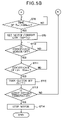
- FIGS. 5A and 5B are flowcharts showing the operation of the driving control according to the first embodiment of the invention.
- FIG. 6 is a schematic diagram of an image forming apparatus according to the second embodiment of the invention.
- FIG. 7 is a circuit block diagram of the driving apparatus according to the second embodiment of the invention.
- FIGS. 8A to 8E are time charts showing the operation of the driving apparatus according to the second embodiment of the invention.
- FIGS. 9A to 9C are flowcharts showing the operation of the driving control according to the second embodiment of the invention.
- FIG. 2 shows an image forming apparatus according to a first embodiment of the invention.
- Reference numeral 10 denotes a printer, which is one type of image forming apparatus.
- the invention is applicable to any type of image forming apparatus, including a monochromatic electro-photographic printer, a facsimile machine, a copier, a multi-function printer also having functions of a facsimile machine, and a copier.
- the image forming apparatus is assumed to be a tandem color electro-photographic printer.
- the printer 10 comprises a sheet feeding unit 11 , a toner image forming unit 12 , a fixing unit 13 , and a sheet discharge unit 14 , and an image is formed on a recording medium which is conveyed by a rotating belt member passing over stretched about a plurality of rollers.
- the sheet feeding unit 11 has a sheet cassette 22 , a pick-up roller 23 , a sheet separating unit 24 , a first or primary conveying roller pair 25 , a second or an intermediate conveying roller pair 26 , and a registration roller pair 27 .
- the sheet cassette 22 accommodates a plurality of stacked recording paper sheets 21 as a printing medium.
- the pick-up roller 23 picks up and feeds out the paper sheets 21 one by one from the sheet cassette 22 .
- the separating unit 24 comprises a retard roller 24 A and a feed roller 24 B, for separating the recording paper sheets 21 overlapping each other when they are fed out from the pick-up roller 23 , into each sheet.
- the conveying roller pair 25 and the intermediate conveying roller pair 26 serve to convey the paper sheet 21 , and to correct any skew of the paper sheet 21 .
- the registration roller pair 27 also corrects any skew of the paper sheet 21 immediately before the printing.
- a conveyance sensor 28 is provided on a sheet conveyance path, immediately before (upstream of) the conveying roller pair 25 , to detect the paper sheet 21 .
- the toner image forming unit 12 is provided with a sheet conveying belt 32 for conveying the paper sheet 21 fed from the sheet feeding unit 11 , and black, yellow, magenta and cyan image forming units 29 K, 29 Y, 29 M and 29 C for forming toner images on the paper sheet 21 .
- the printer 10 is a color printer, and black, yellow, magenta and cyan image forming units 29 K, 29 Y, 29 M and 29 C are provided to form toner images of black, yellow, magenta, and cyan.
- a fixing roller pair 30 is provided to fix the toner images having been formed by the black, yellow, magenta and cyan image forming units 29 K, 29 Y, 29 M and 29 C, onto the paper sheet 21 .
- the toner of the toner images attached to the paper sheet 21 is fused, pressed, and fixed on the paper sheet 21 .
- the sheet discharge unit 14 is provided with a discharge roller 31 for discharging or ejecting the paper sheet 21 , on which the toner images have been fixed at the fixing unit 13 .
- the paper sheet 21 having been discharged is placed on a discharging tray, not shown as such, provided on top of the image forming apparatus.
- FIG. 3 is a perspective view showing the driving apparatus according to the first embodiment of the invention.
- a motor unit 40 serving as a drive source is mounted to a frame, not shown, of the printer 10 .
- the motor unit 40 is in the form of a stepping motor, and outputs a driving force, which is transmitted via gears 42 , to an electro-magnetic clutch 41 which serves as a means for selectively interrupting or transmitting the driving force.
- the load unit 43 for the driving apparatus is a medium conveying device for conveying the paper sheet 21 in the printer 21 .
- the load unit 43 consists of the conveying roller pair 25 , as mentioned above.
- the driving force of the motor unit 40 is transmitted via the gears 42 and the electro-magnetic clutch 41 to the conveying roller pair 25 .
- the interruption or transmission of the driving force is achieved by operating the electro-magnetic clutch 41 . That is, when the electro-magnetic clutch 41 is in a connecting (or transmitting) state, the driving force of the motor unit 40 is transmitted to the conveying roller pair 25 .
- the electro-magnetic clutch 41 is in a disconnecting (or interrupting) states the driving force of the motor unit 40 is not transmitted to the conveying roller pair 25 .
- a control device for the driving apparatus according the present embodiment will next be described.
- FIG. 1 is a block diagram showing the configuration of the control device of the driving apparatus according to the first embodiment of the invention.
- the driving apparatus comprises a motor drive circuit 45 , a clutch drive circuit 46 and a CPU 47 .
- the motor drive circuit 45 is a torque control circuit for controlling the motor unit 40 , and serves as a means for switching a drive current.
- the clutch drive circuit 46 serves as a driving force interruption/transmission control unit for controlling the electro-magnetic clutch 41 .
- the CPU 47 performs control over the entire driving apparatus, including control over timing of operation of the clutch drive circuit 46 and the motor drive circuit 45 .
- the CPU 47 serves as a drive timing control unit for controlling the timing of operation, including the starting timing, of the motor drive circuit 45 , and for controlling the motor current.
- the motor drive circuit 45 is provided with a current sensing resistor 48 for sensing the drive current of the motor unit 40 .
- the CUP 47 operates according a program A 1 stored therein (i.e., in a program memory not shown as such), and conducts control over the driving apparatus, i.e., drive control.
- Control signals from the CPU 47 and supplied to the motor drive circuit 45 include a phase signal S 2 for controlling the excitation phase of the motor unit 40 , and a voltage signal S 3 for controlling the motor current value.
- the voltage signal S 3 is output from a DA output port of the CPU 47 .
- Supplied from the CPU 47 to the clutch drive circuit 46 as a control signal is a clutch ON/OFF signal S 1 , and a motor current sensing signal S 4 is input from the current sensing resistor 48 .
- An output signal S 5 of the conveyance sensor 28 is input to the CPU 47 .
- a stepping motor driver of a bipolar drive type such as MTD 2005F manufactured by Shindengen Electric Manufacturing Co., Ltd., TA84002 manufactured by Toshiba Corporation, may be used.
- the motor drive circuit 45 includes, as functional blocks, a comparator 45 a for comparing the voltages, a PWM controller 45 b for varying the PWM (pulse-width modulation) duties based on the result of the comparison at the comparator 45 a , and a driver 45 c for turning on and off the currents.
- the driver 45 c receives a power supply from a drive power source voltage terminal DP.
- the clutch drive circuit 46 supplies or interrupts the voltage to the electromagnetic clutch 41 , and may be formed of transistor circuits. When the clutch ON/OFF signal S 1 is “high,” the electromagnetic clutch is engaged or on. When the clutch ON/OFF signal S 1 is “low,” the electromagnetic clutch is disengaged or off.
- the conveying operation for conveying the paper sheet 21 during printing is first described.
- the paper sheets 21 accommodated in the sheet feeding unit 11 are picked up and fed out by the sheet pick-up roller 23 in the sheet feeding unit 11 .
- the paper sheet 21 is then conveyed toward the conveying roller pair 25 .
- the conveying roller pair 25 is stationary (i.e., is not rotating) before the paper sheet 21 arrives at the position of the conveying roller pair 25 .
- the conveying roller pair 25 starts to rotate when the paper sheet 21 travels a predetermined distance after the paper sheet 21 is detected by the sensor 28 , i.e., when the paper sheet 21 abuts (is expected to abut) on the conveying roller pair 25 . Any skew of the paper sheet 21 is thereby corrected.
- the present embodiment is directed to the driving apparatus which performs rotation and stopping of the conveying roller pair 25 .
- the paper sheet 21 is further conveyed by the intermediate conveying roller pair 26 and the registration roller pair 27 to the toner image forming unit 12 .
- the toner image forming unit 12 forms toner images of black, yellow, magenta and cyan on the paper sheet 21 by means of the black, yellow, magenta and cyan image forming units 29 K, 29 Y, 29 M and 29 C, while conveying the paper sheet 21 by means of the sheet conveying belt 32 .
- the paper sheet 21 on which the toner images have been formed is conveyed to the fixing unit 13 , where heat and pressure are applied by means of the pressure roller 30 , so that the toner images are fixed on the paper sheet 21 .
- the paper sheet 21 on which the toner images have been fixed is conveyed to the sheet discharge unit 14 , where the paper sheet is discharged or ejected to the discharging tray on top of the printer.
- FIGS. 4A to 4D are time charts showing the operation of the driving apparatus according the first embodiment of the invention.
- the horizontal axes in FIGS. 4A to 4D represent time.
- the distances “L 11 ,” and “L 13 ” are also shown along the horizontal axes. In such a case, their lengths along the horizontal axes are represented by the corresponding time lengths.
- the electromagnetic clutch 41 is in the off state (as shown in FIG. 4D ), and the conveying roller pair 25 is not rotating ( FIG. 4A ). However, the motor unit 41 is in the rotating state.
- the CPU 47 raises the voltage of the current setting reference voltage signal S 3 , serving as the motor current setting signal, to a level V 2 (as shown in FIG. 4C ).
- a circuit for increasing the value of the drive current for the motor unit 40 i.e., the value of the motor current will be described later.
- the electromagnetic clutch 41 is not turned on until after the oscillation of the motor unit 40 , due to the increase of the drive current of the motor unit 40 , is stabilized.
- the time Ts taken for the oscillation of the motor unit 40 to be stabilized is 50 to 100 ms.
- the result of the detection of the paper sheet 21 by the conveyance sensor 28 is utilized to simplify the control over timing at which the electromagnetic clutch 41 is turned on.
- the clutch ON/OFF signal S 1 from the CPU 47 is set to be “high,” so that the electromagnetic clutch 41 is turned on (at T 12 as shown in FIG. 4A ).
- the electromagnetic clutch 41 is turned on, the conveying roller pair 25 begins to rotate, and the paper sheet 21 is conveyed to the toner image forming unit 12 .
- the motor load after this period is slightly greater than when the electromagnetic clutch was not connected, i.e., in the off state, because the paper sheet 21 is conveyed by the conveying roller pair 25 .
- increase DL in the motor load is slight because it is due to the increase in the pressure between the conveying roller pair 25 due to the fact that the paper sheet 21 is held between the conveying roller pair 25 and the friction force of the paper sheet 21 with the pick-up roller 23 , the retard roller 24 A, and the feed roller 24 B.
- the output torque to be generated by the motor unit 40 i.e., the motor torque, need not be of a larger value (to an appreciable degree) after the oscillation following the motor load increase at the time of the connection of the electromagnetic clutch 41 is stabilized.
- the drive current varying means for the motor unit 40 is next described.
- a current sensing resistor 48 is connected to the motor drive circuit 45 to sense the drive current of the motor unit 40 , as shown in FIG. 1 .
- the driver 45 c is shown to be connected with the motor unit 40 by a single line, but actually drive currents of different phases are supplied to coils of respective phases provided in the motor unit 40 , via a plurality of conductors, not specifically illustrated as such. Based on the pulse periods determined by the PWM controller 45 b , the driver 45 c determines the currents for the respective phases, and the polarities of the voltages applied to the coils of the respective phases are switched in accordance with the phase signal S 2 supplied from the CPU 47 .
- a current (which is also a “drive current”) corresponding to the drive currents supplied for the motor unit 40 is drawn from the drive power source voltage terminal DP, and is passed through the driver 45 c and through the current sensing resistor 48 .
- the current through the current sensing resistor 48 is converted to a voltage, which is input, as a motor current sensing signal S 4 , to the comparator 45 a in the motor drive circuit 45 .
- the comparator 45 a Also input to the comparator 45 a is the current setting reference voltage signal S 3 , supplied as a voltage signal for controlling the motor current from the CPU 47 .
- the comparator 45 a compares the motor current sensing signal S 4 from the current sensing resistor 48 with the current setting reference voltage signal S 3 from the CPU 47 .
- a signal S 11 indicating the result of the comparison is passed to the PWM controller 45 b .
- the PWM controller 45 b performs the following operation based on the result of the comparison.
- the result of the comparison is represented by the following inequalities: (motor current sensing signal S4) >(current setting reference voltage signal S3) (2) (motor current sensing signal S4) ⁇ (current setting reference voltage signal S3) (3)
- the PWM controller 45 b reduces the on-duty of the PWM.
- the inequality (3) is satisfied, i.e., when the motor current value is smaller than the set value, the PWM controller 45 b increases the on-duty of the PWM.
- the motor current is increased when the on-duty of the PWM is increased.
- the motor current is decreased when the on-duty of the PWM is decreased. Accordingly, the drive current supplied to the motor unit 40 is kept constant according to the current setting reference voltage signal S 3 .
- the current setting reference voltage signal S 3 is set to be a larger value.
- the current setting reference voltage signal S 3 is set to be a smaller value.
- FIGS. 5A and 5B are flowcharts showing the operation of the drive control according to the first embodiment of the invention.
- the CPU 47 repeats judgment on whether sheet feeding has begun. If it judges that the sheet feeding has begun, the CPU 47 sets the voltage of the current setting reference voltage signal S 3 (which is an output of the CPU 47 ) to the level V 1 , in order to set the drive current supplied to the motor unit 40 to a normal, low level, i.e., small level. As a result, the motor current is set to a small value. Then, the motor starting action is taken to start the motor unit 40 . In this case, a phase signal S 2 with acceleration processing in conformity with the increase of the rotation speed required by the motor unit 40 is output.
- the CPU 47 judges whether the paper sheet 21 having been fed has reached the position of the conveyance sensor 28 , i.e., whether the conveyance sensor 28 detects a paper sheet 21 (i.e., whether the output signal S 5 of the conveyance sensor 28 is “turned on.”
- the output signal S 5 of the conveyance sensor 28 is turned on (T 11 in FIG. 4D )
- the voltage of the current setting reference voltage signal S 3 is set to the level V 2 (T 11 in FIG. 4C ), in order to set the motor current to a larger value, as a process for increasing the drive current supplied to the motor unit 40 .
- the electromagnetic clutch 41 is turned on (T 12 in FIG. 4A ). In order to turn on the electromagnetic clutch 41 , the clutch ON/OFF signal S 1 is set to “high.”
- the CPU 47 judges whether the trailing edge of the paper sheet 21 having been fed has passed the position of the conveyance sensor 28 , i.e., whether the output signal S 5 of the conveyance sensor 28 is turned off. If the output signal S 5 of the conveyance sensor 28 is turned off (T 16 in FIG.
- the CPU 47 judges whether the sheet feeding is terminated. If the sheet feeding is not terminated, the above described operation is repeated. If the sheet feeding is terminated, the motor-stopping action is taken, to stop the motor unit 40 , so as to stop the processing.
- the drive current supplied to the motor unit 40 is increased before the electromagnetic clutch 41 is turned on, and after the electromagnetic clutch 41 is turned on, the drive current supplied to the motor unit 40 is returned to a smaller value.
- the motor unit 40 does not pull out even when the load on the motor unit 40 is increased due to the inertia of the load unit 43 , at the time when the electromagnetic clutch 41 is turned on.
- the drive current is returned to a small value after the electromagnetic clutch 41 is turned on, so that the drive current can be kept to be a small value except for a short period during which the electromagnetic clutch 41 is turned on, and the load on the motor unit 40 increases. Accordingly, it is possible to prevent excessive torque state during normal driving, thereby preventing oscillation and noises of the motor unit 40 from becoming large, and preventing wear of the gears from becoming fast.
- FIG. 6 is a schematic view of the image forming apparatus according to the second embodiment of the invention.
- FIG. 7 is a circuit block diagram of a driving apparatus according to the second embodiment of the invention.
- a printer 10 according to the present embodiment is provided with a sheet reversing unit 15 for reversing the paper sheet 21 .
- the sheet reversing unit 15 comprises a paper sheet retracting route 52 for reversal, and a roller pair 51 for conveying the paper sheet 21 after the reversal.
- Provided on the upstream side of the intermediate conveying roller pair 26 is an intermediate conveyance sensor 53 .
- the output signal S 6 from the intermediate conveyance sensor 53 is input to the CPU 47 .
- the driving apparatus has a configuration shown in FIG. 7 .
- the CPU 47 performs control over the entire driving apparatus, i.e., the drive control according to the program A 2 stored in the CPU 47 (i.e., in a program memory not shown as such).
- Input to the CPU 47 is the output signal S 6 from the intermediate conveyance sensor 53 .
- FIGS. 8A to 8E are time charts showing the operation of the driving apparatus according to the second embodiment.
- the conveying operation for conveying the paper sheet 21 during the printing is first described.
- the paper sheet 21 accommodated in the sheet feeding unit 11 are picked up and fed out by the sheet pick-up roller 23 in the sheet feeding unit 11 .
- the paper sheet 21 is then conveyed toward the conveying roller pair 25 .
- the conveying roller pair 25 is stationary before the paper sheet 21 arrives at the position of the conveying roller pair 25 .
- the conveying roller pair 25 starts to rotate when the paper sheet 21 travels a predetermined distance after the paper sheet 21 is detected by the sensor 28 , i.e., when the paper sheet 21 abuts on the conveying roller pair 25 . Any skew of the paper sheet 21 is thereby corrected.
- the paper sheet 21 is further conveyed by the intermediate conveying roller pair 26 and the registration roller pair 27 to the toner image forming unit 12 .
- the toner image forming unit 12 forms toner images of black, yellow, magenta and cyan, on the paper sheet 21 by means of the black, yellow, magenta and cyan image forming units 29 K, 29 Y, 29 M and 29 C, while conveying the paper sheet 21 by means of the sheet conveying belt 32 .
- the paper sheet 21 on which the toner images have been formed is conveyed to the fixing unit 13 , where heat and pressure are applied by means of the fixing roller 30 , so that the toner images are fixed on the paper sheet 21 .
- the paper sheet 21 on which the toner images have been fixed is conveyed to the sheet discharge unit 14 , and discharged or ejected, by means of the discharge roller 31 , to the discharging tray on top of the printer.
- the paper sheets 21 are fed out from the sheet feeding unit 11 one after another, in succession, and the paper sheets 21 re-fed from the sheet reversing unit 15 and the paper sheets 21 fed from the sheet feeding unit 21 need to be alternately fed to the intermediate conveying roller pair 26 .
- the paper sheet 21 re-fed from the sheet reversing unit 15 is fed to the intermediate conveying roller pair 26
- the paper sheet 21 fed from the sheet feeding unit 11 is halted at a position PA (upstream of the intermediate conveying roller pair 26 and downstream of the conveying roller pair 25 ) as shown in FIG. 6 .
- PA upstream of the intermediate conveying roller pair 26 and downstream of the conveying roller pair 25
- the distance L 14 from the position PA to the intermediate conveying roller pair 26 is 45 mm, and the distance L 15 from the conveying roller pair 25 to the position PA is 50 mm.
- the paper sheet 21 fed from the sheet feeding unit 11 is identified as paper sheet 21 - 1
- the paper sheet 21 re-fed from the sheet reversing unit 15 is identified as paper sheet 21 - 2 .
- the operation similar to that of the first embodiment is performed. If the re-fed paper sheet 21 - 2 is judged to be present, the electromagnetic clutch 41 is turned off (at T 22 as shown in FIG. 8A ), and the conveyance of the paper sheet 21 - 1 is halted.
- the electromagnetic clutch 41 is not turned on until after the oscillation of the motor unit 40 , due to the increase of the drive current of the motor unit 40 , is stabilized.
- the time Ts taken for the oscillation of the motor unit 40 to be stabilized is 50 to 100 ms.
- the present embodiment utilizes the result of the detection of the paper sheet 21 - 2 re-fed to the intermediate conveyance sensor 53 to simplify the control over timing at which the electromagnetic clutch 41 is turned on.
- the voltage of the voltage signal S 3 which is the current setting reference voltage signal, and serves as the motor current setting signal is raised to the level V 2 at T 23 as shown in FIG. 8C , to increase the drive current value of the motor unit 40 .
- the electromagnetic clutch 41 is turned on at T 24 as shown in FIG. 8A , to re-start or resume the conveyance of the paper sheet 21 - 1 .
- the motor load at the time when the electromagnetic clutch 41 is turned on is increased suddenly when the motor unit 40 is connected to the load unit 43 , as shown in FIG. 8B , and as in the first embodiment. This is because of the inertia component of the conveying roller 25 of the load unit 43 , and because the load unit 43 having been stationary begins to rotate and the rotation speed rises to the speed of the motor unit 40 within in a short period of time, upon turning-on of the electromagnetic clutch 41 and the resultant connection of the motor unit 40 with the load section 12 .
- the high motor load continues for 30 ms until the electromagnetic clutch 41 is completely coupled (T 25 ). In other words, the time Tp taken for the electromagnetic clutch 41 to be completely coupled and the motor load to return to a level close to the level before the clutch was turned on is about 30 ms.
- the motor load after this period is slightly larger than when the electromagnetic clutch was not connected, i.e., in the off state, because the paper sheet 21 is conveyed by the conveying roller pair 25 .
- increase DL in the motor load is slight because it is due to the increase in the pressure between the conveying roller pair 25 due to the fact that the paper sheet 21 is held between the conveying roller pair 25 and the friction force of the paper sheet 21 with the pick-up roller 23 , the retard roller 24 A, and the feed roller 24 B.
- the output torque to be generated by the motor unit 40 i.e., the motor torque, need not be of a larger value (to an appreciable degree) after the oscillation following the motor load increase at the time of the connection of the electromagnetic clutch 41 is stabilized.
- FIGS. 9A to 9C are flowcharts showing the operation of the drive control according to the second embodiment of the invention.
- the CPU 47 sets the voltage of the current setting reference voltage signal S 3 to the level V 1 , and the motor unit 40 is made to start.
- the output signal S 5 of the conveyance sensor 28 is turned on (T 11 in FIG. 8D )
- the voltage of the current setting reference voltage signal S 3 is set to the level V 2 (T 11 in FIG. 8C ).
- the electromagnetic clutch 41 is turned on (T 12 in FIG. 8A )
- the voltage of the current setting reference voltage signal S 3 is set to the level V 1 (T 15 in FIG. 8C ).
- the operation so far is identical to that of the first embodiment, so that only the outline has been set forth.
- the output signal S 6 of the intermediate conveyance sensor 53 is shown to be turned on at T 21 before the output signal S 5 of the conveyance sensor 28 is turned on at T 11 .
- the CPU 47 switches the electromagnetic clutch 41 off (T 22 in FIG. 8A ).
- the paper sheet 21 - 2 is assumed to be detected since a time point T 21 .
- the voltage of the current setting reference voltage signal S 3 is set to the level V 2 (T 23 in FIG. 8C ), to set the motor current to a large value.
- the CPU 47 then starts to monitor whether the trailing edge of the paper sheet 21 - 1 has passed the position of the conveyance sensor 28 , i.e., whether the output signal S 5 of the conveyance sensor 28 is turned off.
- the drive current supplied to the motor unit 40 is increased before the electromagnetic clutch 41 is turned on, and after the electromagnetic clutch 41 is turned on, the drive current supplied to the motor unit 40 is returned to a smaller value.
- the motor unit 40 does not pull out even when the load on the motor unit 40 is increased due to the inertia of the load unit 43 , at the time when the electromagnetic clutch 41 is turned on.
- the drive current is returned to a small value after the electromagnetic clutch 41 is turned on, so that the drive current can be kept to be a small value except for a short period during which the electromagnetic clutch 41 is turned on, and the load on the motor unit 40 increases. Accordingly, it is possible to prevent excessive torque state during normal driving, thereby preventing oscillation and noises of the motor unit 40 from becoming large, and preventing wear of the gears from becoming fast.
- the image forming apparatus is a printer.
- the invention can be applied to facsimile machine, MFP (multi function printer), copier, other types of electronic devices having similar driving apparatus.
Abstract
Description
- (a) a drive source outputting a drive force;
- (b) a drive force interruption/transmission device for transmitting or interrupting the drive force from the drive source;
- (c) a load unit operating by the drive force transmitted from the drive force interruption/transmission device;
- (d) a torque control unit for varying the output torque of the drive source;
- (e) a drive force interruption control unit for controlling the operation of the drive force interruption/transmission device; and
- (f) a drive timing control unit for controlling the torque control unit and the drive force interruption/transmission control unit;
- (g) wherein after the output torque of the drive force is increased the drive force from the drive source is transmitted to the load unit.
Tt=L11/Vc=25 [mm]/180 [mm/s]=139[ms] (1)
(motor current sensing signal S4) >(current setting reference voltage signal S3) (2)
(motor current sensing signal S4) <(current setting reference voltage signal S3) (3)
When the inequality (2) is satisfied, i.e., when the motor current value is larger than the set value, the
- Step ST1: Judgment is made as to whether the sheet feeding has been started. If the sheet feeding has been started, the next step performed is the step ST2. If the sheet feeding has not been started, “waiting” action is continued.
- Step ST2: The voltage of the current setting reference voltage signal S3, which is an output signal from the
CPU 47, is set to the level V1, in order to set the drive current of themotor unit 40 to a small level. - Step ST3: The
motor unit 40 is started. - Step ST4: Judgment is made as to whether the output signal S5 of the
conveyance sensor 28 is turned on. When the output signal S5 of theconveyance sensor 28 is turned on, the next step performed is the step ST5. If the output signal S5 of theconveyance sensor 28 is not on, the “waiting” action is continued. - Step ST5: The voltage of the current setting reference voltage signal S3, which is an output signal of the
CPU 47, is set to the level V2, in order to set the drive current of themotor unit 40, to a large level. - Step ST6: Judgment is made as to whether the
paper sheet 21 has been conveyed for a distance of L11=25 mm from the state (time point) when the output signal S5 of theconveyance sensor 28 is turned on. If thepaper sheet 21 has been conveyed for L11=25 mm, the next step performed is the step ST7. If thepaper sheet 21 has not been conveyed for L11=25 mm, the “waiting” action is continued. - Step ST7: The clutch ON/OFF signal S1 is set to “high” (H) to turn on the
electromagnetic clutch 41. - Step ST8: Judgment is made as to whether the time length Tw of 200 ms has elapsed after the
electromagnetic clutch 41 is turned on. If the time length of Tw=200 ms has elapsed, the next step performed is the step ST9. If the time length of Tw=200 ms has not elapsed, the “waiting” action is continued. - Step ST9: The voltage of the current setting reference voltage signal S3, which is an output signal of the
CPU 47, is set to the level V1, in order to set the drive current of themotor unit 40 to a small level. - Step ST10: Judgment is made as to whether the output signal S5 of the
conveyance sensor 28 has been turned off. If the output signal S5 of theconveyance sensor 28 has been turned off, the next step performed is the Step ST11. If the output signal S5 of theconveyance sensor 28 has not been turned off, the “waiting” action is continued. - Step ST11: Judgment is made as to whether the
paper sheet 21 has been conveyed for the distance of L13=30 mm after the turn-off of the output signal S5 of theconveyance sensor 28. If thepaper sheet 21 has been conveyed for the distance of L13=30 mm, the next step performed is the step ST12. If thepaper sheet 21 has not been conveyed for the distance of L13=30 mm, the “waiting” action is continued. - Step ST12: The clutch ON/OFF signal S1 is set to “low” (L) to turn off the
electromagnetic clutch 41. - Step ST13: Judgment is made as to whether the sheet feeding has been terminated. If the sheet feeding has been terminated, the next step performed is the step ST14. If the sheet feeding has not been terminated, the procedure returns to the step ST4.
- Step ST14: The
motor unit 40 is stopped to terminate the process.
- Step ST21: Judgment is made as to whether the sheet feeding has been started. If the sheet feeding has been started, the next step performed is the step ST22. If the sheet feeding has not been started, “waiting” action is continued.
- Step ST22: The voltage of the current setting reference voltage signal S3, which is an output signal from the
CPU 47, is set to the level V1, in order to set the drive current of themotor unit 40 to a small level. - Step ST23: The
motor unit 40 is started. - Step ST24: Judgment is made as to whether the output signal S5 of the
conveyance sensor 28 is turned on. When the output signal S5 of theconveyance sensor 28 is turned on, the next step performed is the step ST25. If the output signal S5 of theconveyance sensor 28 is not on, the “waiting” action is continued. - Step ST25: The voltage of the current setting reference voltage signal S3, which is an output signal of the
CPU 47, is set to the level V2, in order to set the drive current of themotor unit 40, to a large level. - Step ST26: Judgment is made as to whether the
paper sheet 21 has been conveyed for a distance of L11=25 mm from the state (time point) when the output signal S5 of theconveyance sensor 28 is turned on. If thepaper sheet 21 has been conveyed for L11=25 mm, the next step performed is the step ST27. If thepaper sheet 21 has not been conveyed for L11=25 mm, the “waiting” action is continued. - Step ST27: The clutch ON/OFF signal S1 is set to “high” (H), to turn on the
electromagnetic clutch 41. - Step ST28: Judgment is made as to whether the time length Tw of 200 ms has elapsed after the
electromagnetic clutch 41 is turned on. If the time length of Tw=200 ms has elapsed, the next step performed is the step ST29. If the time length of Tw=200 ms has not elapsed, the “waiting” action is continued. - Step ST29: The voltage of the current setting reference voltage signal S3, which is an output signal of the
CPU 47, is set to the level V1, in order to set the drive current of themotor unit 40 to a small level. - Step ST30: Judgment is made as to whether the
paper sheet 21 has been conveyed the distance of L16=50 mm after the state (time point) at which theelectromagnetic clutch 41 is turned on (T12). If thepaper sheet 21 has been conveyed for the distance of L16=50 mm, the next step performed is step ST31. If thepaper sheet 21 has not been conveyed for the distance of L16=50 mm, the “waiting” action is continued. - Step ST31: Judgment is made as to whether the paper sheet 21-2 re-fed from the
sheet reversing unit 15 is present. If the re-fed paper sheet 21-2 is present, the next step performed is the step ST32. If the re-fed paper sheet 21-2 is not present, the next step performed is the step ST36. - Step ST32: The clutch ON/OFF signal S1 is set to “low” (L), to turn off the electromagnetic clutch 41 (T22 in
FIG. 8A ). - Step ST33: The voltage of the current setting reference voltage signal S3, which is an output signal from the
CPU 47, is set to the level V2 (T23 inFIG. 8C ), in order to set the drive current of themotor unit 40 to a large level. - Step ST34: Judgment is made as to whether the paper sheet 21-2 has been conveyed for the distance of L18=25 mm after the
intermediate conveyance sensor 53 ceases to detect the paper sheet 21-2 (i.e., after theintermediate conveyance sensor 53 detects the passage of the trailing edge of the re-fed paper sheet 21-2). If the paper sheet 21-2 has been conveyed for the distance of L18=25 mm, the next step performed is the step ST35. If the paper sheet 21-2 has not been conveyed for the distance of L18=25 mm, the “waiting” action is continued. - Step ST35: The clutch ON/OFF signal S1 is set to “high” (H), to turn on the electromagnetic clutch 41 (T24 in
FIG. 8A ). - Step ST36: Judgment is made as to whether the output signal S5 of the
conveyance sensor 28 has been turned off. If the output signal S5 of theconveyance sensor 28 has been turned off, the next step performed is the Step ST37. If the output signal S5 of theconveyance sensor 28 has not been turned off, the “waiting” action is continued. - Step ST37: Judgment is made as to whether the
paper sheet 21 has been conveyed for the distance of L13=30 mm after the turn-off of the output signal S5 of theconveyance sensor 28. If thepaper sheet 21 has been conveyed for the distance of L13=30 mm, the next step performed is the step ST38. If thepaper sheet 21 has not been conveyed for the distance of L13=30 mm, the “waiting” action is continued. - Step ST38: The clutch ON/OFF signal S1 is set to “low” (L), to turn off the
electromagnetic clutch 41. - Step ST39: Judgment is made as to whether the sheet feeding has been terminated. If the sheet feeding has been terminated, the next step performed is the step ST40. If the sheet feeding has not been terminated, the procedure returns to the step ST24.
- Step ST40: The
motor unit 40 is stopped to terminate the process.
Claims (7)
Applications Claiming Priority (2)
| Application Number | Priority Date | Filing Date | Title |
|---|---|---|---|
| JP2005078410A JP4863631B2 (en) | 2005-03-18 | 2005-03-18 | Driving device and image forming apparatus having the same |
| JP2005-078410 | 2005-03-18 |
Publications (2)
| Publication Number | Publication Date |
|---|---|
| US20060209156A1 US20060209156A1 (en) | 2006-09-21 |
| US7571907B2 true US7571907B2 (en) | 2009-08-11 |
Family
ID=37009876
Family Applications (1)
| Application Number | Title | Priority Date | Filing Date |
|---|---|---|---|
| US11/378,862 Expired - Fee Related US7571907B2 (en) | 2005-03-18 | 2006-03-17 | Driving apparatus |
Country Status (2)
| Country | Link |
|---|---|
| US (1) | US7571907B2 (en) |
| JP (1) | JP4863631B2 (en) |
Cited By (3)
| Publication number | Priority date | Publication date | Assignee | Title |
|---|---|---|---|---|
| US20080224386A1 (en) * | 2007-03-08 | 2008-09-18 | Akira Kunieda | Sheet conveying device, sheet finisher, sheet feeding device, image forming apparatus, and sheet conveying method |
| US20150210484A1 (en) * | 2014-01-29 | 2015-07-30 | Itoh Denki Co., Ltd. | Transfer apparatus and positioning method of device having motor |
| US20200338916A1 (en) | 2019-04-24 | 2020-10-29 | Canon Kabushiki Kaisha | Motor control apparatus and image forming apparatus |
Families Citing this family (5)
| Publication number | Priority date | Publication date | Assignee | Title |
|---|---|---|---|---|
| TWI276545B (en) * | 2004-07-16 | 2007-03-21 | Benq Corp | Print system capable of detecting an abnormal print condition |
| JP5210724B2 (en) * | 2008-06-20 | 2013-06-12 | 京セラドキュメントソリューションズ株式会社 | Image forming apparatus |
| GB2470953A (en) * | 2009-06-12 | 2010-12-15 | Neopost Technologies | Transport apparatus for documents |
| JP6075100B2 (en) * | 2012-07-31 | 2017-02-08 | 株式会社リコー | Drive device |
| JP6828597B2 (en) * | 2017-05-31 | 2021-02-10 | 株式会社リコー | Image forming device |
Citations (4)
| Publication number | Priority date | Publication date | Assignee | Title |
|---|---|---|---|---|
| JPH1030653A (en) | 1996-07-17 | 1998-02-03 | Oki Data:Kk | Electromagnetic clutch and medium conveying device therewith |
| US5967506A (en) * | 1996-11-22 | 1999-10-19 | Fujitsu Limited | Sheet conveying method and apparatus |
| US6092803A (en) * | 1995-02-08 | 2000-07-25 | Canon Kabushiki Kaisha | Sheet transport apparatus and image forming apparatus |
| US6733009B2 (en) * | 2001-05-10 | 2004-05-11 | Canon Kabushiki Kaisha | Image forming apparatus |
Family Cites Families (2)
| Publication number | Priority date | Publication date | Assignee | Title |
|---|---|---|---|---|
| JP2002369588A (en) * | 2001-06-04 | 2002-12-20 | Fuji Xerox Co Ltd | Imaging apparatus |
| JP2004248372A (en) * | 2003-02-12 | 2004-09-02 | Canon Inc | Image forming apparatus |
-
2005
- 2005-03-18 JP JP2005078410A patent/JP4863631B2/en not_active Expired - Fee Related
-
2006
- 2006-03-17 US US11/378,862 patent/US7571907B2/en not_active Expired - Fee Related
Patent Citations (4)
| Publication number | Priority date | Publication date | Assignee | Title |
|---|---|---|---|---|
| US6092803A (en) * | 1995-02-08 | 2000-07-25 | Canon Kabushiki Kaisha | Sheet transport apparatus and image forming apparatus |
| JPH1030653A (en) | 1996-07-17 | 1998-02-03 | Oki Data:Kk | Electromagnetic clutch and medium conveying device therewith |
| US5967506A (en) * | 1996-11-22 | 1999-10-19 | Fujitsu Limited | Sheet conveying method and apparatus |
| US6733009B2 (en) * | 2001-05-10 | 2004-05-11 | Canon Kabushiki Kaisha | Image forming apparatus |
Cited By (6)
| Publication number | Priority date | Publication date | Assignee | Title |
|---|---|---|---|---|
| US20080224386A1 (en) * | 2007-03-08 | 2008-09-18 | Akira Kunieda | Sheet conveying device, sheet finisher, sheet feeding device, image forming apparatus, and sheet conveying method |
| US7896341B2 (en) * | 2007-03-08 | 2011-03-01 | Ricoh Company, Ltd. | Sheet conveying device, sheet finisher, sheet feeding device, image forming apparatus, and sheet conveying method |
| US20150210484A1 (en) * | 2014-01-29 | 2015-07-30 | Itoh Denki Co., Ltd. | Transfer apparatus and positioning method of device having motor |
| US9617083B2 (en) * | 2014-01-29 | 2017-04-11 | Itoh Denki Co., Ltd. | Transfer apparatus and positioning method of device having motor |
| US20200338916A1 (en) | 2019-04-24 | 2020-10-29 | Canon Kabushiki Kaisha | Motor control apparatus and image forming apparatus |
| US11932031B2 (en) | 2019-04-24 | 2024-03-19 | Canon Kabushiki Kaisha | Motor control apparatus and image forming apparatus |
Also Published As
| Publication number | Publication date |
|---|---|
| JP4863631B2 (en) | 2012-01-25 |
| JP2006256814A (en) | 2006-09-28 |
| US20060209156A1 (en) | 2006-09-21 |
Similar Documents
| Publication | Publication Date | Title |
|---|---|---|
| US7571907B2 (en) | Driving apparatus | |
| US8899581B2 (en) | Image processing apparatus, rotation control method for motor, and computer-readable recording medium | |
| US8322718B2 (en) | Recording medium conveyer capable of effectively conveying recording medium of various types | |
| US8474815B2 (en) | Transport device, image forming device, transport method, and recording medium | |
| US10640315B2 (en) | Drive apparatus and image forming apparatus | |
| US9122224B2 (en) | Image forming apparatus and power supply device | |
| JP4596048B2 (en) | Image forming apparatus and preparation operation execution method | |
| US7556254B2 (en) | Image forming system and paper feeder thereof | |
| US10638006B2 (en) | Sheet conveyance apparatus and image forming apparatus | |
| JP2013077932A (en) | Image reading apparatus | |
| US7751755B2 (en) | Image forming apparatus | |
| JP2007233073A (en) | Image forming apparatus | |
| US10007224B2 (en) | Power supply device changing target voltage depending on operation mode, and image forming device having power supply device | |
| JP6578961B2 (en) | Sheet conveying apparatus, image processing apparatus, and sheet conveying control method | |
| JP4827699B2 (en) | Image forming system and paper feeding device thereof | |
| US20130195498A1 (en) | Power control device, electronic apparatus, and image forming apparatus | |
| US20190177102A1 (en) | Paper conveyance device, image forming apparatus, paper conveyance control method, and recording medium | |
| US10234800B2 (en) | Control device and image forming apparatus | |
| EP1731970A2 (en) | Control apparatus system | |
| US11079704B2 (en) | Image forming apparatus with rotating guide member that guides sheet | |
| US7587148B2 (en) | Image formation apparatus, an image formation method, an image formation program, and a recording medium | |
| JP2011230894A (en) | Image forming apparatus | |
| US11841665B2 (en) | Image forming apparatus | |
| JP2018002346A (en) | Sheet transport device | |
| US20240012355A1 (en) | Image forming apparatus |
Legal Events
| Date | Code | Title | Description |
|---|---|---|---|
| AS | Assignment |
Owner name: OKI DATA CORPORATION, JAPAN Free format text: ASSIGNMENT OF ASSIGNORS INTEREST;ASSIGNOR:SHINYAMA, HIDEKI;REEL/FRAME:017724/0129 Effective date: 20060525 |
|
| STCF | Information on status: patent grant |
Free format text: PATENTED CASE |
|
| FEPP | Fee payment procedure |
Free format text: PAYOR NUMBER ASSIGNED (ORIGINAL EVENT CODE: ASPN); ENTITY STATUS OF PATENT OWNER: LARGE ENTITY |
|
| CC | Certificate of correction | ||
| FPAY | Fee payment |
Year of fee payment: 4 |
|
| FPAY | Fee payment |
Year of fee payment: 8 |
|
| FEPP | Fee payment procedure |
Free format text: MAINTENANCE FEE REMINDER MAILED (ORIGINAL EVENT CODE: REM.); ENTITY STATUS OF PATENT OWNER: LARGE ENTITY |
|
| LAPS | Lapse for failure to pay maintenance fees |
Free format text: PATENT EXPIRED FOR FAILURE TO PAY MAINTENANCE FEES (ORIGINAL EVENT CODE: EXP.); ENTITY STATUS OF PATENT OWNER: LARGE ENTITY |
|
| STCH | Information on status: patent discontinuation |
Free format text: PATENT EXPIRED DUE TO NONPAYMENT OF MAINTENANCE FEES UNDER 37 CFR 1.362 |
|
| FP | Lapsed due to failure to pay maintenance fee |
Effective date: 20210811 |