US7585301B2 - Modular hip inserter/positioner - Google Patents
Modular hip inserter/positioner Download PDFInfo
- Publication number
- US7585301B2 US7585301B2 US10/170,129 US17012902A US7585301B2 US 7585301 B2 US7585301 B2 US 7585301B2 US 17012902 A US17012902 A US 17012902A US 7585301 B2 US7585301 B2 US 7585301B2
- Authority
- US
- United States
- Prior art keywords
- piece
- shaft
- implant
- positioning tool
- rotation
- Prior art date
- Legal status (The legal status is an assumption and is not a legal conclusion. Google has not performed a legal analysis and makes no representation as to the accuracy of the status listed.)
- Expired - Fee Related, expires
Links
Images


Classifications
-
- A—HUMAN NECESSITIES
- A61—MEDICAL OR VETERINARY SCIENCE; HYGIENE
- A61F—FILTERS IMPLANTABLE INTO BLOOD VESSELS; PROSTHESES; DEVICES PROVIDING PATENCY TO, OR PREVENTING COLLAPSING OF, TUBULAR STRUCTURES OF THE BODY, e.g. STENTS; ORTHOPAEDIC, NURSING OR CONTRACEPTIVE DEVICES; FOMENTATION; TREATMENT OR PROTECTION OF EYES OR EARS; BANDAGES, DRESSINGS OR ABSORBENT PADS; FIRST-AID KITS
- A61F2/00—Filters implantable into blood vessels; Prostheses, i.e. artificial substitutes or replacements for parts of the body; Appliances for connecting them with the body; Devices providing patency to, or preventing collapsing of, tubular structures of the body, e.g. stents
- A61F2/02—Prostheses implantable into the body
- A61F2/30—Joints
- A61F2/32—Joints for the hip
- A61F2/36—Femoral heads ; Femoral endoprostheses
- A61F2/3609—Femoral heads or necks; Connections of endoprosthetic heads or necks to endoprosthetic femoral shafts
-
- A—HUMAN NECESSITIES
- A61—MEDICAL OR VETERINARY SCIENCE; HYGIENE
- A61F—FILTERS IMPLANTABLE INTO BLOOD VESSELS; PROSTHESES; DEVICES PROVIDING PATENCY TO, OR PREVENTING COLLAPSING OF, TUBULAR STRUCTURES OF THE BODY, e.g. STENTS; ORTHOPAEDIC, NURSING OR CONTRACEPTIVE DEVICES; FOMENTATION; TREATMENT OR PROTECTION OF EYES OR EARS; BANDAGES, DRESSINGS OR ABSORBENT PADS; FIRST-AID KITS
- A61F2/00—Filters implantable into blood vessels; Prostheses, i.e. artificial substitutes or replacements for parts of the body; Appliances for connecting them with the body; Devices providing patency to, or preventing collapsing of, tubular structures of the body, e.g. stents
- A61F2/02—Prostheses implantable into the body
- A61F2/30—Joints
- A61F2/46—Special tools or methods for implanting or extracting artificial joints, accessories, bone grafts or substitutes, or particular adaptations therefor
- A61F2/4603—Special tools or methods for implanting or extracting artificial joints, accessories, bone grafts or substitutes, or particular adaptations therefor for insertion or extraction of endoprosthetic joints or of accessories thereof
- A61F2/4607—Special tools or methods for implanting or extracting artificial joints, accessories, bone grafts or substitutes, or particular adaptations therefor for insertion or extraction of endoprosthetic joints or of accessories thereof of hip femoral endoprostheses
-
- A—HUMAN NECESSITIES
- A61—MEDICAL OR VETERINARY SCIENCE; HYGIENE
- A61F—FILTERS IMPLANTABLE INTO BLOOD VESSELS; PROSTHESES; DEVICES PROVIDING PATENCY TO, OR PREVENTING COLLAPSING OF, TUBULAR STRUCTURES OF THE BODY, e.g. STENTS; ORTHOPAEDIC, NURSING OR CONTRACEPTIVE DEVICES; FOMENTATION; TREATMENT OR PROTECTION OF EYES OR EARS; BANDAGES, DRESSINGS OR ABSORBENT PADS; FIRST-AID KITS
- A61F2/00—Filters implantable into blood vessels; Prostheses, i.e. artificial substitutes or replacements for parts of the body; Appliances for connecting them with the body; Devices providing patency to, or preventing collapsing of, tubular structures of the body, e.g. stents
- A61F2/02—Prostheses implantable into the body
- A61F2/30—Joints
- A61F2/32—Joints for the hip
- A61F2/36—Femoral heads ; Femoral endoprostheses
- A61F2/3662—Femoral shafts
- A61F2/367—Proximal or metaphyseal parts of shafts
-
- A—HUMAN NECESSITIES
- A61—MEDICAL OR VETERINARY SCIENCE; HYGIENE
- A61F—FILTERS IMPLANTABLE INTO BLOOD VESSELS; PROSTHESES; DEVICES PROVIDING PATENCY TO, OR PREVENTING COLLAPSING OF, TUBULAR STRUCTURES OF THE BODY, e.g. STENTS; ORTHOPAEDIC, NURSING OR CONTRACEPTIVE DEVICES; FOMENTATION; TREATMENT OR PROTECTION OF EYES OR EARS; BANDAGES, DRESSINGS OR ABSORBENT PADS; FIRST-AID KITS
- A61F2/00—Filters implantable into blood vessels; Prostheses, i.e. artificial substitutes or replacements for parts of the body; Appliances for connecting them with the body; Devices providing patency to, or preventing collapsing of, tubular structures of the body, e.g. stents
- A61F2/02—Prostheses implantable into the body
- A61F2/30—Joints
- A61F2002/30001—Additional features of subject-matter classified in A61F2/28, A61F2/30 and subgroups thereof
- A61F2002/30108—Shapes
- A61F2002/3011—Cross-sections or two-dimensional shapes
- A61F2002/30138—Convex polygonal shapes
- A61F2002/30143—Convex polygonal shapes hexagonal
-
- A—HUMAN NECESSITIES
- A61—MEDICAL OR VETERINARY SCIENCE; HYGIENE
- A61F—FILTERS IMPLANTABLE INTO BLOOD VESSELS; PROSTHESES; DEVICES PROVIDING PATENCY TO, OR PREVENTING COLLAPSING OF, TUBULAR STRUCTURES OF THE BODY, e.g. STENTS; ORTHOPAEDIC, NURSING OR CONTRACEPTIVE DEVICES; FOMENTATION; TREATMENT OR PROTECTION OF EYES OR EARS; BANDAGES, DRESSINGS OR ABSORBENT PADS; FIRST-AID KITS
- A61F2/00—Filters implantable into blood vessels; Prostheses, i.e. artificial substitutes or replacements for parts of the body; Appliances for connecting them with the body; Devices providing patency to, or preventing collapsing of, tubular structures of the body, e.g. stents
- A61F2/02—Prostheses implantable into the body
- A61F2/30—Joints
- A61F2002/30001—Additional features of subject-matter classified in A61F2/28, A61F2/30 and subgroups thereof
- A61F2002/30316—The prosthesis having different structural features at different locations within the same prosthesis; Connections between prosthetic parts; Special structural features of bone or joint prostheses not otherwise provided for
- A61F2002/30329—Connections or couplings between prosthetic parts, e.g. between modular parts; Connecting elements
- A61F2002/30331—Connections or couplings between prosthetic parts, e.g. between modular parts; Connecting elements made by longitudinally pushing a protrusion into a complementarily-shaped recess, e.g. held by friction fit
- A61F2002/30332—Conically- or frustoconically-shaped protrusion and recess
-
- A—HUMAN NECESSITIES
- A61—MEDICAL OR VETERINARY SCIENCE; HYGIENE
- A61F—FILTERS IMPLANTABLE INTO BLOOD VESSELS; PROSTHESES; DEVICES PROVIDING PATENCY TO, OR PREVENTING COLLAPSING OF, TUBULAR STRUCTURES OF THE BODY, e.g. STENTS; ORTHOPAEDIC, NURSING OR CONTRACEPTIVE DEVICES; FOMENTATION; TREATMENT OR PROTECTION OF EYES OR EARS; BANDAGES, DRESSINGS OR ABSORBENT PADS; FIRST-AID KITS
- A61F2/00—Filters implantable into blood vessels; Prostheses, i.e. artificial substitutes or replacements for parts of the body; Appliances for connecting them with the body; Devices providing patency to, or preventing collapsing of, tubular structures of the body, e.g. stents
- A61F2/02—Prostheses implantable into the body
- A61F2/30—Joints
- A61F2002/30001—Additional features of subject-matter classified in A61F2/28, A61F2/30 and subgroups thereof
- A61F2002/30316—The prosthesis having different structural features at different locations within the same prosthesis; Connections between prosthetic parts; Special structural features of bone or joint prostheses not otherwise provided for
- A61F2002/30535—Special structural features of bone or joint prostheses not otherwise provided for
- A61F2002/30537—Special structural features of bone or joint prostheses not otherwise provided for adjustable
- A61F2002/30538—Special structural features of bone or joint prostheses not otherwise provided for adjustable for adjusting angular orientation
- A61F2002/3054—Special structural features of bone or joint prostheses not otherwise provided for adjustable for adjusting angular orientation about a connection axis or implantation axis for selecting any one of a plurality of radial orientations between two modular parts, e.g. Morse taper connections, at discrete positions, angular positions or continuous positions
-
- A—HUMAN NECESSITIES
- A61—MEDICAL OR VETERINARY SCIENCE; HYGIENE
- A61F—FILTERS IMPLANTABLE INTO BLOOD VESSELS; PROSTHESES; DEVICES PROVIDING PATENCY TO, OR PREVENTING COLLAPSING OF, TUBULAR STRUCTURES OF THE BODY, e.g. STENTS; ORTHOPAEDIC, NURSING OR CONTRACEPTIVE DEVICES; FOMENTATION; TREATMENT OR PROTECTION OF EYES OR EARS; BANDAGES, DRESSINGS OR ABSORBENT PADS; FIRST-AID KITS
- A61F2/00—Filters implantable into blood vessels; Prostheses, i.e. artificial substitutes or replacements for parts of the body; Appliances for connecting them with the body; Devices providing patency to, or preventing collapsing of, tubular structures of the body, e.g. stents
- A61F2/02—Prostheses implantable into the body
- A61F2/30—Joints
- A61F2002/30001—Additional features of subject-matter classified in A61F2/28, A61F2/30 and subgroups thereof
- A61F2002/30316—The prosthesis having different structural features at different locations within the same prosthesis; Connections between prosthetic parts; Special structural features of bone or joint prostheses not otherwise provided for
- A61F2002/30535—Special structural features of bone or joint prostheses not otherwise provided for
- A61F2002/30604—Special structural features of bone or joint prostheses not otherwise provided for modular
- A61F2002/30616—Sets comprising a plurality of prosthetic parts of different sizes or orientations
-
- A—HUMAN NECESSITIES
- A61—MEDICAL OR VETERINARY SCIENCE; HYGIENE
- A61F—FILTERS IMPLANTABLE INTO BLOOD VESSELS; PROSTHESES; DEVICES PROVIDING PATENCY TO, OR PREVENTING COLLAPSING OF, TUBULAR STRUCTURES OF THE BODY, e.g. STENTS; ORTHOPAEDIC, NURSING OR CONTRACEPTIVE DEVICES; FOMENTATION; TREATMENT OR PROTECTION OF EYES OR EARS; BANDAGES, DRESSINGS OR ABSORBENT PADS; FIRST-AID KITS
- A61F2/00—Filters implantable into blood vessels; Prostheses, i.e. artificial substitutes or replacements for parts of the body; Appliances for connecting them with the body; Devices providing patency to, or preventing collapsing of, tubular structures of the body, e.g. stents
- A61F2/02—Prostheses implantable into the body
- A61F2/30—Joints
- A61F2002/30001—Additional features of subject-matter classified in A61F2/28, A61F2/30 and subgroups thereof
- A61F2002/30667—Features concerning an interaction with the environment or a particular use of the prosthesis
- A61F2002/3071—Identification means; Administration of patients
-
- A—HUMAN NECESSITIES
- A61—MEDICAL OR VETERINARY SCIENCE; HYGIENE
- A61F—FILTERS IMPLANTABLE INTO BLOOD VESSELS; PROSTHESES; DEVICES PROVIDING PATENCY TO, OR PREVENTING COLLAPSING OF, TUBULAR STRUCTURES OF THE BODY, e.g. STENTS; ORTHOPAEDIC, NURSING OR CONTRACEPTIVE DEVICES; FOMENTATION; TREATMENT OR PROTECTION OF EYES OR EARS; BANDAGES, DRESSINGS OR ABSORBENT PADS; FIRST-AID KITS
- A61F2/00—Filters implantable into blood vessels; Prostheses, i.e. artificial substitutes or replacements for parts of the body; Appliances for connecting them with the body; Devices providing patency to, or preventing collapsing of, tubular structures of the body, e.g. stents
- A61F2/02—Prostheses implantable into the body
- A61F2/30—Joints
- A61F2/30767—Special external or bone-contacting surface, e.g. coating for improving bone ingrowth
- A61F2/30771—Special external or bone-contacting surface, e.g. coating for improving bone ingrowth applied in original prostheses, e.g. holes or grooves
- A61F2002/30795—Blind bores, e.g. of circular cross-section
- A61F2002/30797—Blind bores, e.g. of circular cross-section internally-threaded
-
- A—HUMAN NECESSITIES
- A61—MEDICAL OR VETERINARY SCIENCE; HYGIENE
- A61F—FILTERS IMPLANTABLE INTO BLOOD VESSELS; PROSTHESES; DEVICES PROVIDING PATENCY TO, OR PREVENTING COLLAPSING OF, TUBULAR STRUCTURES OF THE BODY, e.g. STENTS; ORTHOPAEDIC, NURSING OR CONTRACEPTIVE DEVICES; FOMENTATION; TREATMENT OR PROTECTION OF EYES OR EARS; BANDAGES, DRESSINGS OR ABSORBENT PADS; FIRST-AID KITS
- A61F2/00—Filters implantable into blood vessels; Prostheses, i.e. artificial substitutes or replacements for parts of the body; Appliances for connecting them with the body; Devices providing patency to, or preventing collapsing of, tubular structures of the body, e.g. stents
- A61F2/02—Prostheses implantable into the body
- A61F2/30—Joints
- A61F2/30767—Special external or bone-contacting surface, e.g. coating for improving bone ingrowth
- A61F2/30771—Special external or bone-contacting surface, e.g. coating for improving bone ingrowth applied in original prostheses, e.g. holes or grooves
- A61F2002/30795—Blind bores, e.g. of circular cross-section
- A61F2002/30813—Stepped or enlarged blind bores, e.g. having discrete diameter changes
-
- A—HUMAN NECESSITIES
- A61—MEDICAL OR VETERINARY SCIENCE; HYGIENE
- A61F—FILTERS IMPLANTABLE INTO BLOOD VESSELS; PROSTHESES; DEVICES PROVIDING PATENCY TO, OR PREVENTING COLLAPSING OF, TUBULAR STRUCTURES OF THE BODY, e.g. STENTS; ORTHOPAEDIC, NURSING OR CONTRACEPTIVE DEVICES; FOMENTATION; TREATMENT OR PROTECTION OF EYES OR EARS; BANDAGES, DRESSINGS OR ABSORBENT PADS; FIRST-AID KITS
- A61F2/00—Filters implantable into blood vessels; Prostheses, i.e. artificial substitutes or replacements for parts of the body; Appliances for connecting them with the body; Devices providing patency to, or preventing collapsing of, tubular structures of the body, e.g. stents
- A61F2/02—Prostheses implantable into the body
- A61F2/30—Joints
- A61F2/32—Joints for the hip
- A61F2/36—Femoral heads ; Femoral endoprostheses
- A61F2/3609—Femoral heads or necks; Connections of endoprosthetic heads or necks to endoprosthetic femoral shafts
- A61F2002/3625—Necks
-
- A—HUMAN NECESSITIES
- A61—MEDICAL OR VETERINARY SCIENCE; HYGIENE
- A61F—FILTERS IMPLANTABLE INTO BLOOD VESSELS; PROSTHESES; DEVICES PROVIDING PATENCY TO, OR PREVENTING COLLAPSING OF, TUBULAR STRUCTURES OF THE BODY, e.g. STENTS; ORTHOPAEDIC, NURSING OR CONTRACEPTIVE DEVICES; FOMENTATION; TREATMENT OR PROTECTION OF EYES OR EARS; BANDAGES, DRESSINGS OR ABSORBENT PADS; FIRST-AID KITS
- A61F2/00—Filters implantable into blood vessels; Prostheses, i.e. artificial substitutes or replacements for parts of the body; Appliances for connecting them with the body; Devices providing patency to, or preventing collapsing of, tubular structures of the body, e.g. stents
- A61F2/02—Prostheses implantable into the body
- A61F2/30—Joints
- A61F2/32—Joints for the hip
- A61F2/36—Femoral heads ; Femoral endoprostheses
- A61F2/3609—Femoral heads or necks; Connections of endoprosthetic heads or necks to endoprosthetic femoral shafts
- A61F2002/3652—Connections of necks to shafts
-
- A—HUMAN NECESSITIES
- A61—MEDICAL OR VETERINARY SCIENCE; HYGIENE
- A61F—FILTERS IMPLANTABLE INTO BLOOD VESSELS; PROSTHESES; DEVICES PROVIDING PATENCY TO, OR PREVENTING COLLAPSING OF, TUBULAR STRUCTURES OF THE BODY, e.g. STENTS; ORTHOPAEDIC, NURSING OR CONTRACEPTIVE DEVICES; FOMENTATION; TREATMENT OR PROTECTION OF EYES OR EARS; BANDAGES, DRESSINGS OR ABSORBENT PADS; FIRST-AID KITS
- A61F2/00—Filters implantable into blood vessels; Prostheses, i.e. artificial substitutes or replacements for parts of the body; Appliances for connecting them with the body; Devices providing patency to, or preventing collapsing of, tubular structures of the body, e.g. stents
- A61F2/02—Prostheses implantable into the body
- A61F2/30—Joints
- A61F2/46—Special tools or methods for implanting or extracting artificial joints, accessories, bone grafts or substitutes, or particular adaptations therefor
- A61F2/4603—Special tools or methods for implanting or extracting artificial joints, accessories, bone grafts or substitutes, or particular adaptations therefor for insertion or extraction of endoprosthetic joints or of accessories thereof
- A61F2002/4625—Special tools or methods for implanting or extracting artificial joints, accessories, bone grafts or substitutes, or particular adaptations therefor for insertion or extraction of endoprosthetic joints or of accessories thereof with relative movement between parts of the instrument during use
- A61F2002/4627—Special tools or methods for implanting or extracting artificial joints, accessories, bone grafts or substitutes, or particular adaptations therefor for insertion or extraction of endoprosthetic joints or of accessories thereof with relative movement between parts of the instrument during use with linear motion along or rotating motion about the instrument axis or the implantation direction, e.g. telescopic, along a guiding rod, screwing inside the instrument
-
- A—HUMAN NECESSITIES
- A61—MEDICAL OR VETERINARY SCIENCE; HYGIENE
- A61F—FILTERS IMPLANTABLE INTO BLOOD VESSELS; PROSTHESES; DEVICES PROVIDING PATENCY TO, OR PREVENTING COLLAPSING OF, TUBULAR STRUCTURES OF THE BODY, e.g. STENTS; ORTHOPAEDIC, NURSING OR CONTRACEPTIVE DEVICES; FOMENTATION; TREATMENT OR PROTECTION OF EYES OR EARS; BANDAGES, DRESSINGS OR ABSORBENT PADS; FIRST-AID KITS
- A61F2/00—Filters implantable into blood vessels; Prostheses, i.e. artificial substitutes or replacements for parts of the body; Appliances for connecting them with the body; Devices providing patency to, or preventing collapsing of, tubular structures of the body, e.g. stents
- A61F2/02—Prostheses implantable into the body
- A61F2/30—Joints
- A61F2/46—Special tools or methods for implanting or extracting artificial joints, accessories, bone grafts or substitutes, or particular adaptations therefor
- A61F2/4603—Special tools or methods for implanting or extracting artificial joints, accessories, bone grafts or substitutes, or particular adaptations therefor for insertion or extraction of endoprosthetic joints or of accessories thereof
- A61F2002/4629—Special tools or methods for implanting or extracting artificial joints, accessories, bone grafts or substitutes, or particular adaptations therefor for insertion or extraction of endoprosthetic joints or of accessories thereof connected to the endoprosthesis or implant via a threaded connection
-
- A—HUMAN NECESSITIES
- A61—MEDICAL OR VETERINARY SCIENCE; HYGIENE
- A61F—FILTERS IMPLANTABLE INTO BLOOD VESSELS; PROSTHESES; DEVICES PROVIDING PATENCY TO, OR PREVENTING COLLAPSING OF, TUBULAR STRUCTURES OF THE BODY, e.g. STENTS; ORTHOPAEDIC, NURSING OR CONTRACEPTIVE DEVICES; FOMENTATION; TREATMENT OR PROTECTION OF EYES OR EARS; BANDAGES, DRESSINGS OR ABSORBENT PADS; FIRST-AID KITS
- A61F2/00—Filters implantable into blood vessels; Prostheses, i.e. artificial substitutes or replacements for parts of the body; Appliances for connecting them with the body; Devices providing patency to, or preventing collapsing of, tubular structures of the body, e.g. stents
- A61F2/02—Prostheses implantable into the body
- A61F2/30—Joints
- A61F2/46—Special tools or methods for implanting or extracting artificial joints, accessories, bone grafts or substitutes, or particular adaptations therefor
- A61F2002/4681—Special tools or methods for implanting or extracting artificial joints, accessories, bone grafts or substitutes, or particular adaptations therefor by applying mechanical shocks, e.g. by hammering
-
- A—HUMAN NECESSITIES
- A61—MEDICAL OR VETERINARY SCIENCE; HYGIENE
- A61F—FILTERS IMPLANTABLE INTO BLOOD VESSELS; PROSTHESES; DEVICES PROVIDING PATENCY TO, OR PREVENTING COLLAPSING OF, TUBULAR STRUCTURES OF THE BODY, e.g. STENTS; ORTHOPAEDIC, NURSING OR CONTRACEPTIVE DEVICES; FOMENTATION; TREATMENT OR PROTECTION OF EYES OR EARS; BANDAGES, DRESSINGS OR ABSORBENT PADS; FIRST-AID KITS
- A61F2220/00—Fixations or connections for prostheses classified in groups A61F2/00 - A61F2/26 or A61F2/82 or A61F9/00 or A61F11/00 or subgroups thereof
- A61F2220/0025—Connections or couplings between prosthetic parts, e.g. between modular parts; Connecting elements
- A61F2220/0033—Connections or couplings between prosthetic parts, e.g. between modular parts; Connecting elements made by longitudinally pushing a protrusion into a complementary-shaped recess, e.g. held by friction fit
-
- A—HUMAN NECESSITIES
- A61—MEDICAL OR VETERINARY SCIENCE; HYGIENE
- A61F—FILTERS IMPLANTABLE INTO BLOOD VESSELS; PROSTHESES; DEVICES PROVIDING PATENCY TO, OR PREVENTING COLLAPSING OF, TUBULAR STRUCTURES OF THE BODY, e.g. STENTS; ORTHOPAEDIC, NURSING OR CONTRACEPTIVE DEVICES; FOMENTATION; TREATMENT OR PROTECTION OF EYES OR EARS; BANDAGES, DRESSINGS OR ABSORBENT PADS; FIRST-AID KITS
- A61F2230/00—Geometry of prostheses classified in groups A61F2/00 - A61F2/26 or A61F2/82 or A61F9/00 or A61F11/00 or subgroups thereof
- A61F2230/0002—Two-dimensional shapes, e.g. cross-sections
- A61F2230/0017—Angular shapes
-
- A—HUMAN NECESSITIES
- A61—MEDICAL OR VETERINARY SCIENCE; HYGIENE
- A61F—FILTERS IMPLANTABLE INTO BLOOD VESSELS; PROSTHESES; DEVICES PROVIDING PATENCY TO, OR PREVENTING COLLAPSING OF, TUBULAR STRUCTURES OF THE BODY, e.g. STENTS; ORTHOPAEDIC, NURSING OR CONTRACEPTIVE DEVICES; FOMENTATION; TREATMENT OR PROTECTION OF EYES OR EARS; BANDAGES, DRESSINGS OR ABSORBENT PADS; FIRST-AID KITS
- A61F2250/00—Special features of prostheses classified in groups A61F2/00 - A61F2/26 or A61F2/82 or A61F9/00 or A61F11/00 or subgroups thereof
- A61F2250/0058—Additional features; Implant or prostheses properties not otherwise provided for
- A61F2250/0085—Identification means; Administration of patients
- A61F2250/0089—Identification means; Administration of patients coded with symbols, e.g. dots, numbers, letters, words
Definitions
- the invention relates generally to arthroplasty and, more particularly, to devices and techniques for positioning a prosthesis.
- the surgeon must estimate the degree of implant rotation and begin the implantation in an undesirable orientation with the expectation that the implant will be properly orientated at the completion of implantation. If optimal implant neck version is not attained, the surgeon must decide whether to leave the implant in a non-optimal orientation and risk possible dislocation, or extract the implant and re-implant.
- a positioning tool for inserting an implant provides independent control of the orientation between a first component and a second component of the implant.
- a positioning tool comprises a first piece for engaging a first component of an implant and controlling an orientation thereof; a second piece for engaging a second component of the implant; and a third piece for controlling an orientation of the engaged second component such that the engaged first and second components of the implant do not lock together and wherein the first piece and the third piece provide independent version control for the first and second components of the implant.
- a modular hip body/stem inserter with independent version control of body and stem comprises two parts: a stem inserter and holder.
- the stem inserter also comprises a handle, while the holder comprises a grip.
- a proximal body portion of an implant is loaded, or mounted, onto the holder.
- a distal stem portion of the implant is affixed onto the stem inserter.
- the modular hip body/stem inserter maintains the proximal body portion and distal stem portion a short distance apart to prevent these implant components from locking together (e.g., via a taper locking mechanism).
- the stem inserter can be adjusted, e.g., via the handle, to control the version of the distal stem, while the holder can be independently adjusted, e.g., via the grip, to control the version of the proximal body.
- the stem inserter portion of the modular hip body/stem inserter is removed and the holder is then used to impact the proximal body and distal stem together, thereby locking the implant components together through the taper locking mechanism—thus, setting the final implant seating position.
- FIG. 1 shows a side cross-sectional view of a hip implant
- FIG. 2A shows a side cross-sectional view of an illustrative embodiment of a positioning tool in accordance with the principles of the invention
- FIG. 2B shows an end view of the positioning tool shown in FIG. 2A .
- FIG. 3A is a side cross-sectional view of the positioning tool
- FIG. 3B is a sectional view taken along line B-B of FIG. 3 .
- FIG. 4A is a side cross-sectional view illustrating use of a hip positioning tool with the hip implant of FIG. 1 ;
- FIG. 4B is an end view of the tool shown in FIG. 4A ;
- FIG. 5A shows a top plan view of the proximal body of the hip implant shown in FIG. 1 ;
- FIG. 5B is a sectional view taken along line A-A of FIG. 5A ;
- FIG. 5C is a sectional view taken along line D-D of FIG. 5A ;
- FIG. 6A shows a side cross-sectional view of the holder portion of the tool shown in FIG. 2 ;
- FIG. 6B is a perspective view of the holder portion at the tool shown in FIG. 2 ;
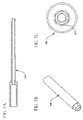
- FIG. 7A is a side cross-sectional view of the shaft portion of the tool shown in FIG. 2 ;
- FIG. 7B is a perspective view of the shaft portion of the tool shown in FIG. 2 ;
- FIG. 7C is an enlarged distal end view of the shaft portion of the tool.
- FIG. 8 shows a side cross-sectional view of threaded rod 160 .
- FIG. 9 shows a side cross-sectional view of the sleeve portion of the tool shown in FIG. 2 .
- inventive concept is illustrated in the context of a hip body/stem inserter used in orthopedic hip implants.
- inventive concept familiarity with hip implants, and the components used therein, is assumed and not described further herein.
- a locking taper for self-locking pieces of an implant together is well known and not described herein as is a ball detent comprising a spring, ball bearing and associated groove.
- inventive concept is not limited to hip implants and applies to any implant application requiring version, or orientation, control of different portions of the implant.
- Hip implant 50 comprises two components: a proximal body 20 and a fluted distal stem 10 (only a portion of which is shown in FIG. 1 ).
- Proximal body 20 comprises upright portion 21 for receiving a ball head (not shown), a receptacle 23 , opening 24 and a tapered portion 22 .
- Distal stem 10 also comprises a tapered portion 12 . Tapered portions 12 and 22 are interlocking tapers as known in the art such that when distal stem 10 is fully seated into opening 24 of proximal body 20 —distal stem 10 and proximal body 20 are locked together.
- Distal stem 10 further comprises female hex end 13 and threaded female portion 11 (both described further below).
- FIGS. 2A and 2B An embodiment of the invention is shown in FIGS. 2A and 2B with respect to a modular hip body/stem inserter (inserter) 100 .
- the latter is used, in accordance with one aspect of the invention, to position the hip implant 50 into a femur (not shown) such that there is independent control of the orientation of the components, or portions, of the implant, here represented by proximal body 20 and distal stem 10 .
- proximal body 20 and distal stem 10 here represented by proximal body 20 and distal stem 10 .
- the surgeon can now independently adjust the orientation of the various parts of the implant.
- Inserter 100 comprises a holder (or proximal body impactor) 130 , a sleeve 140 , a shaft 150 , a rod (or pin) 160 having a threaded male end 161 (rod 160 is hereafter referred to as threaded rod 160 ), a spring 170 , and a ball detent 180 .
- inserter 100 also comprises a handle 105 , which is coupled to shaft 150 .
- stem inserter refers either to shaft 150 or threaded rod 160 , or their combination.
- shaft 150 can be easily modified to provide the functions of rod 160 .
- rod 160 could be modified to provide the functions of shaft 150 .
- threaded rod 160 is disposed within shaft 150 , which is also disposed within holder 130 .
- Sleeve 140 which includes spring 170 , surrounds holder 130 and is used to position holder 130 on shaft 150 (described further below). (It should be noted that sleeve 140 could also be integrated with holder 130 .)
- Ball detent 180 is mounted on distal end portion 131 of holder 130 . It should be observed that threaded rod 160 , in the direction of distal end portion 131 , extends beyond shaft 150 .
- shaft 150 comprises, at the distal end, end 151 , which is illustratively hexagon shaped (hereafter, male hex end 151 ). The latter mates with the female hex end 13 of distal stem 10 (described further below).
- the position of shaft 150 with respect to holder 130 is adjustable.
- Shaft 150 further comprises, at the proximal end, circular grooves (as represented by groove 152 ) and holder 130 comprises, at the proximal end, ball detent pair 132 .
- ball detent pair 132 will periodically engage one of the grooves of shaft 150 —thus allowing the position of holder 130 with respect to shaft 150 to be adjusted in finite increments.
- inserter 100 to accommodate different size lengths of proximal body 20 such that at least a distance d is maintained between the affixed proximal body 20 and affixed distal stem 10 .
- maintaining at least a separation distance d prevents the proximal body and the distal stem from locking together for allowing independent adjustment of their orientations.
- other equivalent forms of adjustment may be used such as, but not limited to, using threaded elements for adjustment of the shaft and holder, wire clips, etc.
- inserter 100 provides for independent version control about an axis z, via shaft 150 , and holder 130 .
- holder 130 can be rotated in direction 1
- shaft 150 can be rotated in direction 2 —thus, an adjustment to the orientation of holder 130 is independent of any adjustment to the orientation of shaft 150 .
- proximal body 20 is first mounted to holder 130 of inserter 100 such that receptacle 23 mates with ball detent 180 .
- the latter provides a secure, temporary, mounting of proximal body 20 to holder 130 of inserter 100 .
- threaded male end 161 of threaded rod 160 , extends into the opening within proximal body 20 beyond shaft 150 .
- FIG. 3B further illustrates the use of ball detent 180 for temporarily mounting proximal body 20 onto holder 130 .
- distal stem 10 is attached to threaded rod 160 . This is illustrated in FIGS. 4A and 4B .
- distal stem 10 is inserted into opening 24 of proximal body 20 such that threaded male end 161 , of threaded rod 160 , engages female threaded portion 11 of distal stem 10 .
- female hex end 13 of distal stem 10 is drawn onto male hex end 151 of shaft 150 .
- the implant components are rigidly held together—without taper portion 22 , of proximal body 20 , or taper portion 12 , of distal stem 10 , engaging. This is illustrated in FIG. 4A by the separation distance, d, between distal stem 10 and proximal body 20 .
- threaded male end 161 locks distal stem 10 to inserter 100 and male hex end 151 enables shaft 150 to provide rotational control of distal stem 10 , via female hex end 13 .
- other forms of attachment can be used to affix distal stem 10 to rod 160 .
- inserter 100 initially maintains the taper portions of both proximal body 20 and distal stem 10 apart by at least a distance d, such that they do not lock together. Indeed, and as described above, holder 130 can slide, or move, up or down on shaft 150 for providing this separation distance for different length proximal bodies.
- the orientation of proximal body 20 is adjusted by movement, or rotation, of holder 130 , in either direction about an axis z, e.g., in direction 3 of FIG. 4B .
- This movement can be facilitated by placement of a grip on holder 130 , or alternatively using the upright portion 21 of proximal body 20 .
- holder 130 is free to move around shaft 150 —any change to the orientation of proximal body 20 via rotation of holder 130 does not affect the orientation of distal stem 10 .
- the orientation of distal stem 10 is adjusted by rotation of shaft 150 , via handle 105 , in either direction about axis z, e.g., in direction 4 of FIG.
- inserter 100 provides for independent version control of proximal body 20 and distal stem 10 as the construct is impacted (i.e., as the inserter 100 plus implant 50 is inserted into the femur). As the implant approaches the final seating position (e.g., 5 mm-mm) continual adjustments can be made to the orientations of proximal body 20 and distal stem 10 .
- holder 130 is then used to impact the proximal body and distal stem together (e.g., through use of a hammer), thereby locking the implant components together through the taper locking mechanism—thus, setting the final implant seating position for the assembled implant. Further impacting of holder 130 fully seats the assembled implant in the femur.
- FIGS. 5-9 provide individual views (not to scale) of the various above-described parts of implant 50 and inserter 100 for reference purposes and are not described further herein.
- FIGS. 5A-C show proximal body 20 of the implant 50 in top plan and sectional views.
- FIGS. 6A and 6B illustrate holder 130 with locations 133 and 134 for ball detent pair 132 .
- FIGS. 7A-C show various views of shaft 150 , illustrating male hex end 151 .
- FIG. 8 illustrates threaded rod 160 .
- FIG. 9 shows sleeve 140 .
- the modular hip body/stem inserter with independent version control of body and stem rectifies the problem of neck version control on modular implants by allowing the proximal body and the distal stem to be implanted simultaneously while independently controlling the version, or orientation, of the proximal body and distal stem.
Abstract
Description
Claims (29)
Priority Applications (2)
| Application Number | Priority Date | Filing Date | Title |
|---|---|---|---|
| US10/170,129 US7585301B2 (en) | 2002-06-12 | 2002-06-12 | Modular hip inserter/positioner |
| US12/459,330 US7998147B2 (en) | 2002-06-12 | 2009-06-30 | Modular hip inserter/positioner |
Applications Claiming Priority (1)
| Application Number | Priority Date | Filing Date | Title |
|---|---|---|---|
| US10/170,129 US7585301B2 (en) | 2002-06-12 | 2002-06-12 | Modular hip inserter/positioner |
Related Child Applications (1)
| Application Number | Title | Priority Date | Filing Date |
|---|---|---|---|
| US12/459,330 Division US7998147B2 (en) | 2002-06-12 | 2009-06-30 | Modular hip inserter/positioner |
Publications (2)
| Publication Number | Publication Date |
|---|---|
| US20030233100A1 US20030233100A1 (en) | 2003-12-18 |
| US7585301B2 true US7585301B2 (en) | 2009-09-08 |
Family
ID=29732422
Family Applications (2)
| Application Number | Title | Priority Date | Filing Date |
|---|---|---|---|
| US10/170,129 Expired - Fee Related US7585301B2 (en) | 2002-06-12 | 2002-06-12 | Modular hip inserter/positioner |
| US12/459,330 Expired - Fee Related US7998147B2 (en) | 2002-06-12 | 2009-06-30 | Modular hip inserter/positioner |
Family Applications After (1)
| Application Number | Title | Priority Date | Filing Date |
|---|---|---|---|
| US12/459,330 Expired - Fee Related US7998147B2 (en) | 2002-06-12 | 2009-06-30 | Modular hip inserter/positioner |
Country Status (1)
| Country | Link |
|---|---|
| US (2) | US7585301B2 (en) |
Cited By (15)
| Publication number | Priority date | Publication date | Assignee | Title |
|---|---|---|---|---|
| US20100106159A1 (en) * | 2006-05-01 | 2010-04-29 | Greatbatch Medical Sa | Inserter For Minimally Invasive Joint Surgery Having an Interchangeable Prosthesis Engaging Piston |
| US20110218537A1 (en) * | 2010-03-05 | 2011-09-08 | Biomet Manufacturing Corp. | Method and Apparatus for Preparing a Proximal Femur |
| US20110218640A1 (en) * | 2010-03-05 | 2011-09-08 | Biomet Manufacturing Corp. | Method and Apparatus for Trialing and Implanting a Modular Femoral Hip |
| US20110218583A1 (en) * | 2010-03-05 | 2011-09-08 | Biomet Manufacturing Corp. | Assembly Tool for Modular Implants and Associated Method |
| US20110218641A1 (en) * | 2010-03-05 | 2011-09-08 | Biomet Manufacturing Corp. | Modular Lateral Hip Augments |
| US20110218636A1 (en) * | 2010-03-05 | 2011-09-08 | Biomet Manufacturing Corp. | Guide Assembly for Lateral Implants and Associated Methods |
| US20110218582A1 (en) * | 2010-03-05 | 2011-09-08 | Biomet Manufacturing Corp. | Method and Apparatus for Implanting a Modular Femoral Hip |
| US8277457B1 (en) | 2004-12-09 | 2012-10-02 | Greatbatch Medical S.A. | Orthopaedic inserter using a collet mechanism |
| US8398650B1 (en) | 2009-01-27 | 2013-03-19 | Greatbatch Medical S.A. | Offset cup impactor with an expandable dome for double mobility implants |
| US8585709B2 (en) | 2011-01-17 | 2013-11-19 | Greatbatch Medical S.A. | Straight cup impactor with lever arm |
| US8870886B2 (en) | 2011-08-26 | 2014-10-28 | Greatbatch Medical S.A. | Straight cup impactor |
| US8961528B2 (en) | 2010-08-27 | 2015-02-24 | Greatbatch Medical S.A. | Offset cup impactor with a grasping plate for double mobility implants |
| US9028502B2 (en) | 2011-09-23 | 2015-05-12 | Greatbatch Medical S.A. | Ceramic implant holder |
| US9084685B2 (en) * | 2012-09-28 | 2015-07-21 | DePuy Synthes Products, Inc. | Femoral prosthesis with insertion/extraction feature |
| US9119731B2 (en) | 2011-01-17 | 2015-09-01 | Greatbach Medical S.A. | Straight cup impactor |
Families Citing this family (30)
| Publication number | Priority date | Publication date | Assignee | Title |
|---|---|---|---|---|
| US8057482B2 (en) | 2003-06-09 | 2011-11-15 | OrthAlign, Inc. | Surgical orientation device and method |
| US7559931B2 (en) | 2003-06-09 | 2009-07-14 | OrthAlign, Inc. | Surgical orientation system and method |
| DE202005014270U1 (en) * | 2005-09-09 | 2007-01-11 | Waldemar Link Gmbh & Co. Kg | Insertion aid for femur implant, comprises guiding unit for striker and particularly safe holding arrangement |
| US20070288096A1 (en) * | 2006-06-02 | 2007-12-13 | Gabriel Surma | System and method for inserting an implant |
| US8303601B2 (en) | 2006-06-07 | 2012-11-06 | Stryker Spine | Collet-activated distraction wedge inserter |
| EP1918915B1 (en) * | 2006-10-31 | 2014-03-05 | Thomson Licensing | Method for producing a security mark on an optical data carrier |
| US8372121B2 (en) * | 2007-02-08 | 2013-02-12 | Warsaw Orthopedic, Inc. | Adjustable coupling systems for spinal stabilization members |
| DE202007007322U1 (en) * | 2007-05-23 | 2008-10-02 | Baumgart, Rainer, Prof. Dr.med., Dipl.-Ing. | Set of instruments for the minimally invasive preparation of a bone nailing |
| GB0716403D0 (en) * | 2007-08-22 | 2007-10-03 | Benoist Girard Sas | Trial prosthetic neck component |
| US20090099566A1 (en) * | 2007-10-10 | 2009-04-16 | Maness Megan A | Modular stem inserter |
| US8597336B2 (en) * | 2007-12-28 | 2013-12-03 | Howmedica Osteonics Corp. | Apparatus for discrete tissue anchoring for soft tissue repair and method of use |
| US20100069911A1 (en) | 2008-07-24 | 2010-03-18 | OrthAlign, Inc. | Systems and methods for joint replacement |
| US8777990B2 (en) * | 2008-09-08 | 2014-07-15 | Howmedica Osteonics Corp. | Knotless suture anchor for soft tissue repair and method of use |
| AU2009291743B2 (en) | 2008-09-10 | 2015-02-05 | Orthalign, Inc | Hip surgery systems and methods |
| US9451942B2 (en) * | 2008-11-12 | 2016-09-27 | Howmedica Osteonics Corp. | Insertion tool for knotless suture anchor for soft tissue repair and method of use |
| US8123815B2 (en) | 2008-11-24 | 2012-02-28 | Biomet Manufacturing Corp. | Multiple bearing acetabular prosthesis |
| US8308810B2 (en) | 2009-07-14 | 2012-11-13 | Biomet Manufacturing Corp. | Multiple bearing acetabular prosthesis |
| US10869771B2 (en) | 2009-07-24 | 2020-12-22 | OrthAlign, Inc. | Systems and methods for joint replacement |
| US8118815B2 (en) | 2009-07-24 | 2012-02-21 | OrthAlign, Inc. | Systems and methods for joint replacement |
| US8876835B2 (en) * | 2009-12-28 | 2014-11-04 | Safe Orthopaedics | Device for positioning an implant |
| AU2011341678B2 (en) | 2010-01-21 | 2014-12-11 | OrthAlign, Inc. | Systems and methods for joint replacement |
| AU2013262624B2 (en) | 2012-05-18 | 2018-03-01 | OrthAlign, Inc. | Devices and methods for knee arthroplasty |
| US9649160B2 (en) | 2012-08-14 | 2017-05-16 | OrthAlign, Inc. | Hip replacement navigation system and method |
| US9241811B2 (en) | 2012-09-14 | 2016-01-26 | Biomet Manufacturing, Llc | Method and apparatus for implanting a prosthesis |
| US9439780B2 (en) | 2012-09-14 | 2016-09-13 | Biomet Manufacturing, Llc | Acetabular cup inserter handle |
| US9763806B2 (en) | 2012-10-23 | 2017-09-19 | Biomet Manufacturing, Llc | Method and apparatus for implanting a prosthesis |
| WO2014075025A1 (en) * | 2012-11-12 | 2014-05-15 | Ziran Navid | Dynamic axial nail for intramedullary treatment of long bone fractures |
| US10363149B2 (en) | 2015-02-20 | 2019-07-30 | OrthAlign, Inc. | Hip replacement navigation system and method |
| JP7344122B2 (en) | 2017-03-14 | 2023-09-13 | オースアライン・インコーポレイテッド | Systems and methods for measuring and balancing soft tissue |
| CA3056382A1 (en) | 2017-03-14 | 2018-09-20 | OrthAlign, Inc. | Hip replacement navigation systems and methods |
Citations (18)
| Publication number | Priority date | Publication date | Assignee | Title |
|---|---|---|---|---|
| US5409492A (en) | 1993-08-09 | 1995-04-25 | Stelkast Incorporated | System for coupling an implant to a tool for inserting and removing the implant |
| US5571111A (en) | 1995-05-01 | 1996-11-05 | Aboczky; Robert I. | Instrument for orienting, inserting and impacting an acetabular cup prosthesis including prosthesis retaining head arrangement |
| US5645549A (en) | 1995-04-24 | 1997-07-08 | Danek Medical, Inc. | Template for positioning interbody fusion devices |
| US5913860A (en) | 1998-02-27 | 1999-06-22 | Synthes (Usa) | Surgical nail inserter |
| US6033405A (en) | 1994-09-15 | 2000-03-07 | Surgical Dynamics, Inc. | Apparatus and method for implant insertion |
| US6110211A (en) | 1998-05-01 | 2000-08-29 | Weiss; James M. | Hip replacement methods and apparatus |
| US6110179A (en) | 1998-03-02 | 2000-08-29 | Benoist Girard Sas | Prosthesis inserter |
| US6117173A (en) | 1995-12-07 | 2000-09-12 | Aesculap Ag & Co., Kg | Orthopaedic fixing system |
| US6136035A (en) * | 1994-11-19 | 2000-10-24 | Merck Patent Gmbh | Modular joint prosthesis |
| US6143030A (en) | 1999-03-26 | 2000-11-07 | Bristol-Myers Squibb Co. | Impaction allograft form and method of orthopaedic surgery using same |
| US6224609B1 (en) | 1998-03-16 | 2001-05-01 | Teramed Inc. | Bifurcated prosthetic graft |
| US6238435B1 (en) | 2000-03-10 | 2001-05-29 | Bristol-Myers Squibb Co | Assembly tool for prosthetic implant |
| US6267785B1 (en) | 1996-02-01 | 2001-07-31 | Medidea, Llc | Apparatus for positioning a prosthetic element to achieve a desired orientation for cementation |
| US6302890B1 (en) | 2000-03-16 | 2001-10-16 | Leone Innovations Corporation | Pelvic alignment assembly |
| US6330845B1 (en) | 2000-05-17 | 2001-12-18 | Bristol-Myers Squibb | Wrench for an implant |
| US6344060B1 (en) | 1998-09-10 | 2002-02-05 | Plus Endoprothetik Ag | Kit for implanting a cementable endoprosthesis |
| US6361565B1 (en) | 1991-08-12 | 2002-03-26 | Peter M. Bonutti | Expandable hip implant |
| US6371991B1 (en) | 1996-12-23 | 2002-04-16 | Depuy Orthopaedics, Inc. | Alignment guide for fluted prosthetic stems |
Family Cites Families (1)
| Publication number | Priority date | Publication date | Assignee | Title |
|---|---|---|---|---|
| US6702854B1 (en) * | 1999-06-01 | 2004-03-09 | Apex Surgical, Llc | Implantable joint prosthesis |
-
2002
- 2002-06-12 US US10/170,129 patent/US7585301B2/en not_active Expired - Fee Related
-
2009
- 2009-06-30 US US12/459,330 patent/US7998147B2/en not_active Expired - Fee Related
Patent Citations (18)
| Publication number | Priority date | Publication date | Assignee | Title |
|---|---|---|---|---|
| US6361565B1 (en) | 1991-08-12 | 2002-03-26 | Peter M. Bonutti | Expandable hip implant |
| US5409492A (en) | 1993-08-09 | 1995-04-25 | Stelkast Incorporated | System for coupling an implant to a tool for inserting and removing the implant |
| US6033405A (en) | 1994-09-15 | 2000-03-07 | Surgical Dynamics, Inc. | Apparatus and method for implant insertion |
| US6136035A (en) * | 1994-11-19 | 2000-10-24 | Merck Patent Gmbh | Modular joint prosthesis |
| US5645549A (en) | 1995-04-24 | 1997-07-08 | Danek Medical, Inc. | Template for positioning interbody fusion devices |
| US5571111A (en) | 1995-05-01 | 1996-11-05 | Aboczky; Robert I. | Instrument for orienting, inserting and impacting an acetabular cup prosthesis including prosthesis retaining head arrangement |
| US6117173A (en) | 1995-12-07 | 2000-09-12 | Aesculap Ag & Co., Kg | Orthopaedic fixing system |
| US6267785B1 (en) | 1996-02-01 | 2001-07-31 | Medidea, Llc | Apparatus for positioning a prosthetic element to achieve a desired orientation for cementation |
| US6371991B1 (en) | 1996-12-23 | 2002-04-16 | Depuy Orthopaedics, Inc. | Alignment guide for fluted prosthetic stems |
| US5913860A (en) | 1998-02-27 | 1999-06-22 | Synthes (Usa) | Surgical nail inserter |
| US6110179A (en) | 1998-03-02 | 2000-08-29 | Benoist Girard Sas | Prosthesis inserter |
| US6224609B1 (en) | 1998-03-16 | 2001-05-01 | Teramed Inc. | Bifurcated prosthetic graft |
| US6110211A (en) | 1998-05-01 | 2000-08-29 | Weiss; James M. | Hip replacement methods and apparatus |
| US6344060B1 (en) | 1998-09-10 | 2002-02-05 | Plus Endoprothetik Ag | Kit for implanting a cementable endoprosthesis |
| US6143030A (en) | 1999-03-26 | 2000-11-07 | Bristol-Myers Squibb Co. | Impaction allograft form and method of orthopaedic surgery using same |
| US6238435B1 (en) | 2000-03-10 | 2001-05-29 | Bristol-Myers Squibb Co | Assembly tool for prosthetic implant |
| US6302890B1 (en) | 2000-03-16 | 2001-10-16 | Leone Innovations Corporation | Pelvic alignment assembly |
| US6330845B1 (en) | 2000-05-17 | 2001-12-18 | Bristol-Myers Squibb | Wrench for an implant |
Non-Patent Citations (3)
| Title |
|---|
| Biomet, Inc., Sundial Version Control Device, 1997 Form No. Y-BMT-502/013197/M. |
| Link America, Inc., The Link(R) MP Reconstruction Hip Stem, 1997, LIT MP-03 97. |
| ZMR(TM) Hip System, Revision Taper, Modular Hip Prosthesis. |
Cited By (33)
| Publication number | Priority date | Publication date | Assignee | Title |
|---|---|---|---|---|
| US8277457B1 (en) | 2004-12-09 | 2012-10-02 | Greatbatch Medical S.A. | Orthopaedic inserter using a collet mechanism |
| US8236004B2 (en) | 2006-05-01 | 2012-08-07 | Greatbatch Medical S.A. | Inserter for minimally invasive joint surgery having an interchangeable prosthesis engaging piston |
| US20100106159A1 (en) * | 2006-05-01 | 2010-04-29 | Greatbatch Medical Sa | Inserter For Minimally Invasive Joint Surgery Having an Interchangeable Prosthesis Engaging Piston |
| US8398650B1 (en) | 2009-01-27 | 2013-03-19 | Greatbatch Medical S.A. | Offset cup impactor with an expandable dome for double mobility implants |
| US8591518B2 (en) | 2010-03-05 | 2013-11-26 | Biomet Manufacturing, Llc | Method and apparatus for implanting a modular femoral hip |
| US8876837B2 (en) | 2010-03-05 | 2014-11-04 | Biomet Manufacturing, Llc | Method and apparatus for implanting a modular femoral hip |
| US20110218582A1 (en) * | 2010-03-05 | 2011-09-08 | Biomet Manufacturing Corp. | Method and Apparatus for Implanting a Modular Femoral Hip |
| US8221432B2 (en) | 2010-03-05 | 2012-07-17 | Biomet Manufacturing Corp. | Method and apparatus for implanting a modular femoral hip |
| US20110218641A1 (en) * | 2010-03-05 | 2011-09-08 | Biomet Manufacturing Corp. | Modular Lateral Hip Augments |
| US20110218583A1 (en) * | 2010-03-05 | 2011-09-08 | Biomet Manufacturing Corp. | Assembly Tool for Modular Implants and Associated Method |
| US8333807B2 (en) * | 2010-03-05 | 2012-12-18 | Biomet Manufacturing Corp. | Method and apparatus for trialing and implanting a modular femoral hip |
| US20110218640A1 (en) * | 2010-03-05 | 2011-09-08 | Biomet Manufacturing Corp. | Method and Apparatus for Trialing and Implanting a Modular Femoral Hip |
| US8419743B2 (en) | 2010-03-05 | 2013-04-16 | Biomet Manufacturing Corp. | Assembly tool for modular implants and associated method |
| US8460393B2 (en) | 2010-03-05 | 2013-06-11 | Biomet Manufacturing Corp. | Modular lateral hip augments |
| US8529569B2 (en) | 2010-03-05 | 2013-09-10 | Biomet Manufacturing, Llc | Method and apparatus for preparing a proximal femur |
| US10188520B2 (en) | 2010-03-05 | 2019-01-29 | Biomet Manufacturing, Llc | Modular lateral hip augments |
| US20110218537A1 (en) * | 2010-03-05 | 2011-09-08 | Biomet Manufacturing Corp. | Method and Apparatus for Preparing a Proximal Femur |
| US8679130B2 (en) | 2010-03-05 | 2014-03-25 | Biomet Manufacturing, Llc | Guide assembly for lateral implants and associated methods |
| US9615942B2 (en) | 2010-03-05 | 2017-04-11 | Biomet Manufacturing, Llc | Method and apparatus for trialing and implanting a modular femoral hip |
| US20110218636A1 (en) * | 2010-03-05 | 2011-09-08 | Biomet Manufacturing Corp. | Guide Assembly for Lateral Implants and Associated Methods |
| US8906109B2 (en) | 2010-03-05 | 2014-12-09 | Biomet Manufacturing, Llc | Modular lateral hip augments |
| US9510950B2 (en) | 2010-03-05 | 2016-12-06 | Biomet Manufacturing, Llc | Modular lateral hip auguments |
| US9339318B2 (en) | 2010-03-05 | 2016-05-17 | Biomet Manufacturing, Llc | Method and apparatus for preparing a proximal femur |
| US9314287B2 (en) | 2010-03-05 | 2016-04-19 | Biomet Manufacturing, Llc | Assembly tool for modular implant and associated method |
| US9138273B2 (en) | 2010-03-05 | 2015-09-22 | Biomet Manufacturing, Llc | Guide assembly for lateral implants and associated methods |
| US8961528B2 (en) | 2010-08-27 | 2015-02-24 | Greatbatch Medical S.A. | Offset cup impactor with a grasping plate for double mobility implants |
| US9119731B2 (en) | 2011-01-17 | 2015-09-01 | Greatbach Medical S.A. | Straight cup impactor |
| US8585709B2 (en) | 2011-01-17 | 2013-11-19 | Greatbatch Medical S.A. | Straight cup impactor with lever arm |
| US8870886B2 (en) | 2011-08-26 | 2014-10-28 | Greatbatch Medical S.A. | Straight cup impactor |
| US9028502B2 (en) | 2011-09-23 | 2015-05-12 | Greatbatch Medical S.A. | Ceramic implant holder |
| US9084685B2 (en) * | 2012-09-28 | 2015-07-21 | DePuy Synthes Products, Inc. | Femoral prosthesis with insertion/extraction feature |
| US10022244B2 (en) | 2012-09-28 | 2018-07-17 | DePuy Synthes Products, Inc. | Method for femoral prosthesis with insertion/extraction feature |
| US10646354B2 (en) | 2012-09-28 | 2020-05-12 | DePuy Synthes Products, Inc. | Kit with femoral prostheses having insertion/extraction features |
Also Published As
| Publication number | Publication date |
|---|---|
| US20030233100A1 (en) | 2003-12-18 |
| US7998147B2 (en) | 2011-08-16 |
| US20090270874A1 (en) | 2009-10-29 |
Similar Documents
| Publication | Publication Date | Title |
|---|---|---|
| US7585301B2 (en) | Modular hip inserter/positioner | |
| US5540697A (en) | Prosthetic socket installation apparatus and method | |
| US5879401A (en) | Acetabular trial | |
| US8152855B2 (en) | Method and apparatus for hip femoral resurfacing tooling | |
| EP1205161B1 (en) | Self-locking modular prosthesis having taper feature and associated method | |
| AU2006225167B2 (en) | Joint prosthesis with positionable head | |
| EP1124511A1 (en) | Anterior lateral spine cage-plate fixation device and technique | |
| US10881514B2 (en) | Implant assembly tools and methods | |
| US10716683B2 (en) | Ball and cup impactors for implanting a hip prosthesis | |
| US8070822B1 (en) | Tool for controlling the mutual angle between the parts of an artificial hip joint | |
| NZ739115B2 (en) | Ball and cup impactors for implanting a hip prosthesis |
Legal Events
| Date | Code | Title | Description |
|---|---|---|---|
| AS | Assignment |
Owner name: HOWMEDICA OSTEONICS CORP., NEW JERSEY Free format text: ASSIGNMENT OF ASSIGNORS INTEREST;ASSIGNORS:SANTARELLA, MICHAEL;PILSBURY, RICHARD H.;COYNE III, MARTIN M.;REEL/FRAME:013275/0234;SIGNING DATES FROM 20020806 TO 20020807 |
|
| STCF | Information on status: patent grant |
Free format text: PATENTED CASE |
|
| FPAY | Fee payment |
Year of fee payment: 4 |
|
| FPAY | Fee payment |
Year of fee payment: 8 |
|
| FEPP | Fee payment procedure |
Free format text: MAINTENANCE FEE REMINDER MAILED (ORIGINAL EVENT CODE: REM.); ENTITY STATUS OF PATENT OWNER: LARGE ENTITY |
|
| LAPS | Lapse for failure to pay maintenance fees |
Free format text: PATENT EXPIRED FOR FAILURE TO PAY MAINTENANCE FEES (ORIGINAL EVENT CODE: EXP.); ENTITY STATUS OF PATENT OWNER: LARGE ENTITY |
|
| STCH | Information on status: patent discontinuation |
Free format text: PATENT EXPIRED DUE TO NONPAYMENT OF MAINTENANCE FEES UNDER 37 CFR 1.362 |
|
| FP | Lapsed due to failure to pay maintenance fee |
Effective date: 20210908 |