US7607653B2 - Systems and methods for maintaining the density of grouped sheet articles - Google Patents
Systems and methods for maintaining the density of grouped sheet articles Download PDFInfo
- Publication number
- US7607653B2 US7607653B2 US11/546,552 US54655206A US7607653B2 US 7607653 B2 US7607653 B2 US 7607653B2 US 54655206 A US54655206 A US 54655206A US 7607653 B2 US7607653 B2 US 7607653B2
- Authority
- US
- United States
- Prior art keywords
- group
- density
- envelopes
- sheet articles
- sheet
- Prior art date
- Legal status (The legal status is an assumption and is not a legal conclusion. Google has not performed a legal analysis and makes no representation as to the accuracy of the status listed.)
- Expired - Fee Related, expires
Links
Images


Classifications
-
- B—PERFORMING OPERATIONS; TRANSPORTING
- B65—CONVEYING; PACKING; STORING; HANDLING THIN OR FILAMENTARY MATERIAL
- B65H—HANDLING THIN OR FILAMENTARY MATERIAL, e.g. SHEETS, WEBS, CABLES
- B65H1/00—Supports or magazines for piles from which articles are to be separated
- B65H1/08—Supports or magazines for piles from which articles are to be separated with means for advancing the articles to present the articles to the separating device
- B65H1/24—Supports or magazines for piles from which articles are to be separated with means for advancing the articles to present the articles to the separating device with means for relieving or controlling pressure of the pile
-
- B—PERFORMING OPERATIONS; TRANSPORTING
- B65—CONVEYING; PACKING; STORING; HANDLING THIN OR FILAMENTARY MATERIAL
- B65H—HANDLING THIN OR FILAMENTARY MATERIAL, e.g. SHEETS, WEBS, CABLES
- B65H1/00—Supports or magazines for piles from which articles are to be separated
- B65H1/02—Supports or magazines for piles from which articles are to be separated adapted to support articles on edge
-
- B—PERFORMING OPERATIONS; TRANSPORTING
- B65—CONVEYING; PACKING; STORING; HANDLING THIN OR FILAMENTARY MATERIAL
- B65H—HANDLING THIN OR FILAMENTARY MATERIAL, e.g. SHEETS, WEBS, CABLES
- B65H31/00—Pile receivers
- B65H31/04—Pile receivers with movable end support arranged to recede as pile accumulates
- B65H31/06—Pile receivers with movable end support arranged to recede as pile accumulates the articles being piled on edge
-
- B—PERFORMING OPERATIONS; TRANSPORTING
- B65—CONVEYING; PACKING; STORING; HANDLING THIN OR FILAMENTARY MATERIAL
- B65H—HANDLING THIN OR FILAMENTARY MATERIAL, e.g. SHEETS, WEBS, CABLES
- B65H2511/00—Dimensions; Position; Numbers; Identification; Occurrences
- B65H2511/20—Location in space
- B65H2511/22—Distance
-
- B—PERFORMING OPERATIONS; TRANSPORTING
- B65—CONVEYING; PACKING; STORING; HANDLING THIN OR FILAMENTARY MATERIAL
- B65H—HANDLING THIN OR FILAMENTARY MATERIAL, e.g. SHEETS, WEBS, CABLES
- B65H2515/00—Physical entities not provided for in groups B65H2511/00 or B65H2513/00
- B65H2515/12—Density
-
- B—PERFORMING OPERATIONS; TRANSPORTING
- B65—CONVEYING; PACKING; STORING; HANDLING THIN OR FILAMENTARY MATERIAL
- B65H—HANDLING THIN OR FILAMENTARY MATERIAL, e.g. SHEETS, WEBS, CABLES
- B65H2515/00—Physical entities not provided for in groups B65H2511/00 or B65H2513/00
- B65H2515/30—Forces; Stresses
- B65H2515/34—Pressure, e.g. fluid pressure
-
- B—PERFORMING OPERATIONS; TRANSPORTING
- B65—CONVEYING; PACKING; STORING; HANDLING THIN OR FILAMENTARY MATERIAL
- B65H—HANDLING THIN OR FILAMENTARY MATERIAL, e.g. SHEETS, WEBS, CABLES
- B65H2553/00—Sensing or detecting means
- B65H2553/10—Sensing or detecting means using fluids, e.g. pneumatics
-
- B—PERFORMING OPERATIONS; TRANSPORTING
- B65—CONVEYING; PACKING; STORING; HANDLING THIN OR FILAMENTARY MATERIAL
- B65H—HANDLING THIN OR FILAMENTARY MATERIAL, e.g. SHEETS, WEBS, CABLES
- B65H2701/00—Handled material; Storage means
- B65H2701/10—Handled articles or webs
- B65H2701/19—Specific article or web
- B65H2701/1916—Envelopes and articles of mail
Definitions
- the subject matter disclosed herein relates generally to processing of sheet articles. More particularly, the subject matter disclosed herein relates to systems and methods for maintaining the density of a group of sheet articles, such as for feeding sheet articles from or to the group.
- Feeding systems and stacker systems discussed herein are frequently an integral part of mail piece inserting systems and mail piece sorting systems.
- envelopes or other sheet articles can be fed to a group of the sheet articles, which also requires pressure maintenance during the feeding process to make room for additional sheet articles.
- a feeding mechanism or a stacker input mechanism imposes pressure control requirements for the group.
- a conventional technique for processing the envelopes involves holding the group of envelopes where they are all in a vertical orientation in a group and where envelopes can be removed for feeding from one end of the group. As envelopes are removed from the group, it is desirable to keep pressure on the group of envelopes to continue the process.
- One way to keep pressure on the group of envelopes is to move a belt under the group of envelopes to adjust and maintain desired pressure on the group.
- some techniques use a mechanism such as a paddle to push against one end of the group of envelopes to apply pressure. In the past, movement of the belt or paddle mechanism has been set to occur during processing of the envelopes at periodic time intervals, such as for example once every 15 milliseconds, to maintain pressure on the remaining envelopes in the group. For a stacker implementation, the process is reversed so that the belt or paddle must be moved every time an envelope is added to the stack to maintain a constant stack pressure.
- novel systems and methods are provided for maintaining the density of grouped sheet articles, such as for feeding of sheet articles from or into the group.
- FIG. 1 of the drawings is a schematic view of portions of a system for holding and feeding sheet articles illustrating a pneumatic air pressure sensor system
- FIGS. 2A , 2 B and 2 C of the drawings are sectional views of an air nozzle that can be used according to one aspect of the present disclosure and showing air flow through the air nozzle;
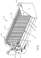
- FIG. 3 is a perspective view of a portion of a system for holding and feeding sheet articles according to one aspect of the present disclosure
- FIG. 4 is a perspective view showing an opposite side of the system for holding and feeding sheet articles shown in FIG. 3 ;
- FIGS. 5A , 5 B and 5 C of the drawings are isolated perspective views of a support portion of a system for holding and feeding sheet articles according to one aspect of the present disclosure with FIGS. 5B and 5C showing support of different sized groups of sheet articles;
- FIG. 5D is a perspective view of a sheet article stacker system used to add sheet articles to a group of sheet articles
- FIG. 6A of the drawings is a perspective view of a portion of a system for holding and feeding sheet articles, and FIG. 6B is an end view of a portion of the system shown in FIG. 6A ;
- FIGS. 7A and 7B of the drawings are close-up perspective views of portions of a system for holding and feeding sheet articles showing the feeding location and air nozzle(s) location;
- FIGS. 8A , 8 B and 8 C of the drawings are schematic views illustrating sequential steps in removal of a sheet article from a group of sheet articles according to one aspect of the present disclosure.
- FIG. 9 of the drawings is a flow diagram of the control logic used to change the density of a group of sheet articles.
- novel systems and methods are provided for monitoring, adjusting and maintaining pressure on sheet articles in a group, such as for feeding of sheet articles from the group.
- the systems and methods described herein can have particular application for use in sheet processing such as, for example, mail inserting systems, mail sorting systems, and any other sheet processing systems or methods utilizing a group of sheet articles.
- sheet article is used herein to designate any sheet article, and can include, for example and without limitation, envelopes, sheet inserts folded or unfolded for insertion into an envelope or folder, and any other sheet materials.
- envelope feeders and envelope stackers Two common devices, used in mail inserters and mail sorters that feed or stack sheet articles, are envelope feeders and envelope stackers respectively.
- Devices that feed or stack sheet articles require that the group of sheet articles maintain a pressure against the front section of the feeder or stacker at the location or point where the article is either extracted or inserted.
- the pressure insures that the envelope is in a position where the feeding mechanism can acquire the envelope in order to “pull” it out of the group.
- the pressure needs to be controlled since if the pressure is too light, the envelope will not be engaged by the feeder. If the pressure is too high, the feeder may not be able to extract the envelope from the group or more than one envelope will be extracted.
- the pressure insures that the group of envelopes is pressed against the front face where each envelope is inserted into the stack.
- the proper pressure ensures that the group of envelopes is not leaning forward or backward and will exert sufficient pressure on the newly arriving envelope to assist in a controlled stop.
- the controlled stop results from the friction between the newly arriving envelope and the group of envelopes plus the side wall. If the pressure is too high, the friction will be too great, and the new envelope will not be fully added to the stack resulting in poor stack quality, all envelopes not registered against the side wall, or a jam due to little or no insertion into the group.
- An air nozzle and air back pressure measurement device can be used to measure the density of the group of sheet articles by sensing the amount of air reflected back to and through the air nozzle by the group of sheet articles instead of the air passing into or through the group of sheet articles.
- Those skilled in the art may use a variety of terms to relate the pressure that a group of sheet articles may exert on the extraction or insertion point in a sheet article feeder or stacker to the density of the group.
- the pressure that a group of sheet articles exerts is directly related to the density of the group and can be determined by measuring the amount of air reflected back to the sensor.
- the amount of air reflected back to the air nozzle is affected by the amount of air that can be forced into or through the group of sheet articles by an air nozzle.
- FIGS. 3 through 8 One possible representation of a feeding or stacking mechanism that is operable with the pneumatic sensor system is shown in FIGS. 3 through 8 . Other possible representations may exist as those skilled in the art are aware of or could design.
- a pneumatic sensing system as shown in FIG. 1 can be used that includes air nozzle 72 A, a sensor 85 for measuring the pressure of air passing to sensor 85 from air nozzle 72 A, and an air supply 90 .
- Second air nozzle 72 B can be part of another, complete pneumatic sensing system PSS with an identical or similar sensor and air supply.
- Air supply 90 can provide outgoing air 78 , that can be in a stream, through air nozzle 72 A that is directed at a group of sheet articles SA. Some of air stream 78 can pass through the group as indicated by escape air 79 , and some of air stream 78 can be reflected back as indicated by reflected air 80 , that can also be in a stream. Reflected air 80 can pass into air nozzle 72 A where it is directed to air pressure sensor 85 . As shown in FIGS. 2A , 2 B and 2 C and as known to those familiar with pneumatic sensors, air nozzle 72 A can have two air passages therethrough wherein an inner, peripheral air passage 74 can act as a conduit for blowing air therethrough in a direction toward an object.
- a central air passage 76 can be defined centrally through air nozzle 72 A for passage of air therethrough in an opposite direction that has been reflected by an object such as object O in FIG. 2B .
- Object O for the example described is the side edge of a stack of sheet articles SA.
- air 78 can be blown through peripheral air passage 74 of air nozzle 72 A against the side of a group of sheet articles.
- the pressure of reflected air 80 as reflected by the group of sheet articles can return through central air passage 76 of air nozzle 72 A and be measured by sensor 85 .
- the measurement of air pressure of reflected air 80 can indicate the density or pressure of sheet articles in the group.
- the difference in the pressure of outgoing air 78 and reflected air 80 is affected by the density of the stack of sheet articles SA.
- Table 1 shows one example of current values for the stacks of envelopes used on the sheet article processing machine. Those skilled in the art may develop different values based on testing with a variety of sheet article types and feeder or stacker configurations.
- controller 91 can cause motors MA and/or MB to move the belts in a direction to cause the sheet articles in a group to pack more tightly together, or controller 91 can cause motors MA and/or MB to move the belts in an opposite direction to cause the sheet articles in a group to be more loosely packed together.
- An advantage of having two sensor systems is the ability to move sets of belts independently, thereby allowing the system to compensate for skew in the stack of sheet articles.
- FIG. 2C shows an end view of air nozzle 72 A, where output air 78 is supplied by the outside ring and reflected air 80 is returned to the sensor 85 through the center of the nozzle.
- a motor can be implemented to drive plate 28 either separately or in conjunction with the belts to make the adjustment in density or pressure of the group of sheet articles.
- One or more sensors such as sensor 85 can be used to sense the density or pressure of sheet articles in the group, and the measurement can be used with controller 91 for example to control movement of motors MA and/or MB to adjust the density or pressure of sheet articles SA in the group.
- Motors MA or MB can be operated to move any or all of belts B 1 , and B 2 to reduce the density or pressure of sheet articles SA, against input roller 38 and front plate 35 , to allow additional sheet articles to be added to the stack. Even when used with a stacker system, the density or pressure of sheet articles SA in some situations may need to be increased.
- a single sensor 72 A may be used where a stacker system is used, but if sheet articles SA are uniform, then two sensors such as sensors 72 A and 72 B can be employed by adding in slide bars similar to 52 and 54 .
- System 10 can include a support generally designated 20 for supporting a plurality of sheet articles (shown later) in a group.
- Support 20 can include a surface 22 that can be horizontal and elongated for supporting a plurality of vertically oriented sheet articles in a group on top of surface 22 .
- One or more belts such as belts B 1 , B 2 , B 3 , and B 4 can extend at least partially in the direction of surface 22 and can be adapted for moving in a direction toward an end of support 20 as explained in detail further below.
- Support 20 can also include a side wall 24 that can extend vertically in a direction orthogonal to surface 22 and extend horizontally the distance of support 20 .
- Side wall 24 can be used for registration of sheet articles against side wall 24 .
- An end wall 26 can intersect with an end of side wall 24 and extend vertically away from surface 22 .
- a movable plate 28 can be spring loaded and positioned for pressing against the rear of a group of sheet articles. Plate 28 can include a handle 30 for ease of moving plate 28 .
- FIG. 3 of the drawings shows an operator side view of system 10 and FIG. 4 shows the reverse side view.
- One or more groups of sheet articles can be supported on surface 22 of support 20 .
- system 10 as shown in FIG. 3 is configured for supporting two separate groups of vertically oriented sheet articles on surface 22 of support 20 for seriatim feeding of the sheet articles from surface 22 to a sheet feeder such as sheet feeder generally designated SF as explained in detail further below.
- sheet feeder such as sheet feeder generally designated SF
- sheet articles do not have to be maintained in a particular orientation and can be oriented such that the individual sheet articles in a group are on-edge or vertical, or such that the individual sheet articles in a group are horizontal, where they can be stacked, such as for example from under or over accumulation.
- the orientation is a function of the infeed location 40 design or the stacker location (not shown) design.
- Each group of sheet articles can be supported on surface 22 and biased by plate 28 toward a feeding location generally designated 40 . At feeding location 40 , individual sheet articles from each group can be removed and moved into sheet feeder SF for further processing as explained in detail further below.
- System 10 can use any suitable mechanism or system for moving a group of sheet articles on surface 22 .
- plate 28 can be adapted and used for moving a group of sheet articles on surface 22 instead of any belts as can be appreciated by those of skill in the art.
- belts are utilized, just one or more than one belt for moving a group of sheet articles on surface 22 can be utilized.
- FIG. 5A of the drawings provides a close up view of a portion of system 10 including support 20 configured with belts B 1 , B 2 , B 3 and B 4 . As shown in FIG.
- a group of sheet articles generally designated SA shown for example as a group of envelopes, is shown supported on surface 22 where sheet articles SA are registered along one side against side wall 24 and biased by plate 28 toward feeding location 40 .
- plate 28 can be driven to add or remove pressure to a group of sheet articles instead or in addition to the belts.
- the group of sheet articles SA is positioned on top of belts B 1 and B 2 (shown in FIG. 5A ) such that belts B 1 and B 2 can move in a direction toward feeding location 40 in order to maintain a desired pressure of sheet articles SA against one another in the group, which is important for feeding of the sheet articles from the group.
- a sheet article stacker system can operate similarly, but in an opposite direction.
- feeding location 40 can be a location for feeding sheet articles such as envelopes to a group on support 22 , rather than extracting sheet articles from the group as performed by a feeder.
- an envelope is inserted into the stack from the left 39 by the compliant roller 37 and the drive belt 36 .
- Pressure control can be maintained against the input roller 38 and front plate 35 in a similar manner using the same support structures 22 , 24 and using one or more belts, such as B 1 and B 2 (additional belts not shown could also be used) and or a driven movable plate such as plate 28 .
- plate 28 may be spring loaded to ensure a minimum stack pressure.
- Belts B 1 and B 1 and/or plate 28 can be moved as desired each time a sheet article is added to the group based on the sensor operation using an air nozzle 72 A as described further below.
- FIGS. 6A and 6B of the drawings show an example of how belts B 1 , B 2 , B 3 and B 4 can be driven.
- Motor MA can be used for driving belts B 1 and B 2
- motor MB can be used for driving belts B 3 and B 4 .
- motors MA and MB can respectively drive shafts 42 A and 42 B to turn rollers 44 A and 44 B.
- Belts 46 A and 46 B on rollers 44 A and 44 B, respectively, can therefore be driven to rotate and turn pulleys 48 A and 48 B, respectively. Rotation of pulleys 48 A and 48 B rotates shafts 50 A and 50 B, respectively.
- Belts B 1 and B 2 can be attached on rollers on shaft 50 A such that rotation of shaft 50 A rotates belts B 1 and B 2 .
- belts B 3 and B 4 can be attached on rollers on shaft 50 B such that rotation of shaft 50 B rotates belts B 3 and B 4 .
- the use of more than two belts and more than one motor provides a differential drive arrangement helpful for processing larger sheet articles, for example large envelopes known as flats.
- the group of flats F can sit on top of belts B 1 , B 2 , B 3 and B 4 .
- motors MA and MB can be controlled and operated selectively at the same or simultaneously different speeds.
- a side bar 52 shown in FIGS. 5 A and 5 B can be used to assist in aligning a group of sheet articles on surface 22 as they reach feeding location 40 .
- Side bar 52 extends from a side bar base 54 that can be movably attached to a shaft 56 where side bar base 54 can be moved in a transverse direction laterally along shaft 56 by rotation of knob 58 (shown in FIG. 4 ). Side bar base 54 can therefore be adjusted and positioned as desired for positioning of side bar 52 , such as to position side bar 52 between belts B 2 and B 3 as shown in FIG. 5A or to a far side of surface 22 such as outside of belt B 4 as shown in FIG. 5C .
- one or more feeding belts such as feeding belts FB, can be provided at feeding location 40 .
- Feeding belts can have a plurality of vacuum holes H and can be positioned at the end of surface 22 for feeding of sheet articles from a group as described below.
- feeding belt FB can rotate continuously in a downward direction.
- Feeding belt FB can be positioned and exposed through slots defined in a feeding plate that can have an upper feeding plate portion 60 and a lower feeding plate portion 62 .
- Lower feeding plate portion 62 can be pivotally attached with upper feeding plate portion 60 for pivotal movement of lower feeding plate portion 62 as described in more detail below.
- One or more suction cups such as suction cups C, can be attached to lower feeding plate portion 62 .
- separator pins such as pins 70 can be positioned along one or both sides of a feeding end of a group of sheet articles at feeding location 40 and used for facilitating seriatim feeding of a single sheet article from a group as described further below.
- One pair of separator pins 70 can be positioned proximate suction cup C, and another pair of opposing separator pins can be positioned on side bar base 54 .
- One or more air nozzles such as air nozzles 72 A and 72 B can be positioned near separator pins 70 for use with the sensing system described in detail further below.
- a sensing system such as pneumatic sensing system generally designated PSS can be provided to monitor the density or pressure of a group of sheet articles using an air nozzle such as air nozzle 72 A in FIG. 7A for blowing air on against one side of a group of sheet articles on support 22 .
- a second air nozzle 72 B as shown in FIG. 7B can be used to blow air against an opposite side of a group of sheet articles on support 22 .
- the use of at least two, opposing air nozzles can be useful for controlling skew of processed sheet articles, especially when the sheet articles being processed are flats.
- Each air nozzle is connected to its own sensor system PSS and corresponding belt drive motor MA or MB.
- the sensing system can be used to monitor the pressure on surfaces 60 and 62 created by a group of sheet articles SA so that air nozzle 72 A (shown previously) can blow air against the side of sheet articles SA such as, for example, at or near area A. Any other suitable area or areas could also be the target for blown air.
- Air reflected from the sheet articles and passing to the sensor can be used to control movement of belt B 1 .
- the controller can be set and configured to cause movement or no movement of belt B 1 based upon the air pressure sensed.
- the controller can accordingly cause belt B 1 to move toward feeding location 40 in order to increase the pressure of sheet articles against one another in the group.
- the controller can cause belt B 1 to accordingly move away from feeding location 40 in order to decrease the pressure of sheet articles against one another in the group.
- the controller can cause belt B 1 to do nothing.
- At least lower feeding plate portion 62 can move from an unengaged and back position to an engaged and forward position where the suction cups on lower feeding plate portion 62 move forward to engage a sheet article.
- lower feeding plate portion 62 is in this forward position where suction cup C with a vacuum pulling through suction cup C engages the end sheet article SA 1 in preparation for removal and feeding of sheet article SA 1 .
- Sheet article SA 1 can be removed from the group by movement of suction cup C away from the group as shown in FIG. 8B .
- Sheet article SA 1 is pulled back against feeding belt FB where a vacuum pulling through feeding belt FB causes sheet article SA 1 to stay against feeding belt FB. Movement of feeding belt FB with sheet article SA 1 positioned against it further removes sheet article SA 1 for feeding as shown in FIG. 8C .
- the pneumatic sensing and control features of the present disclosure can therefore be used at any or all points during feeding of sheet article SA 1 to dynamically monitor and control the density and pressure of sheet articles SA against one another in the group and against surfaces 60 and 62 or input roller 38 and front plate 35 .
- the density and pressure can be automatically sensed as at 100 .
- the air pressure is below an acceptable range as at 101 , the group is too loosely packed together and adjustments can automatically be made to apply pressure as at 104 to move the stack in the group feeding direction to increase the density of sheet articles in the group.
- the air pressure When the air pressure is above an acceptable range as at 102 , adjustments can automatically be made to reduce pressure as at 105 to move the stack in a direction opposite from the group feeding direction to reduce the density of sheet articles in the group. When the air pressure is within an acceptable range as at 103 , the density is correct and no movement of the group occurs as at 106 .
- the use of more than one pneumatic sensing system allows for independent and automatic monitoring and control of different sides of a group of sheet articles, which can be helpful for controlling skew of sheet articles within the group.
- one system can control one or more belts under one side of the group of sheet articles, and another system can simultaneously control one or more belts under another, opposite side of the group of sheet articles.
- sheet articles SA can be inserted into the group or stack from the side as shown in FIG. 5D . Similar adjustments to the pressure or density of the group can be required for use with a stacker system in order for a sheet article SA 1 to be inserted into the stack. Maintaining the pressure or density of the group is important to operation of a stacker since high pressure or density can prevent a sheet article from fully entering the stack and low pressure or density can result in the sheet article bouncing off the support 24 or sustaining damage to the leading edge of the sheet article.
- the control functions of FIG. 9 can remain the same except that the group can be moved toward or away from the stacker input mechanism.
Abstract
Description
| TABLE 1 | ||||
| Reflected | Variation during | |||
| Out going | air set | operation of | Stack too | Stack too |
| | | reflected | dense | loose |
| 20 to 24 | 1.3 Pascals | 1.8 to 0.8 | ≧2.0 Pascals | ≦0.5 Pascals |
| psig | Pascals | |||
For example,
Claims (22)
Priority Applications (3)
| Application Number | Priority Date | Filing Date | Title |
|---|---|---|---|
| US11/546,552 US7607653B2 (en) | 2006-10-12 | 2006-10-12 | Systems and methods for maintaining the density of grouped sheet articles |
| EP07017894A EP1911703B1 (en) | 2006-10-12 | 2007-09-12 | System and methods for maintaining the density of grouped sheet articles |
| DE602007010222T DE602007010222D1 (en) | 2006-10-12 | 2007-09-12 | System and method for maintaining the density of sheet-like articles in stacks |
Applications Claiming Priority (1)
| Application Number | Priority Date | Filing Date | Title |
|---|---|---|---|
| US11/546,552 US7607653B2 (en) | 2006-10-12 | 2006-10-12 | Systems and methods for maintaining the density of grouped sheet articles |
Publications (2)
| Publication Number | Publication Date |
|---|---|
| US20080088076A1 US20080088076A1 (en) | 2008-04-17 |
| US7607653B2 true US7607653B2 (en) | 2009-10-27 |
Family
ID=38981043
Family Applications (1)
| Application Number | Title | Priority Date | Filing Date |
|---|---|---|---|
| US11/546,552 Expired - Fee Related US7607653B2 (en) | 2006-10-12 | 2006-10-12 | Systems and methods for maintaining the density of grouped sheet articles |
Country Status (3)
| Country | Link |
|---|---|
| US (1) | US7607653B2 (en) |
| EP (1) | EP1911703B1 (en) |
| DE (1) | DE602007010222D1 (en) |
Families Citing this family (7)
| Publication number | Priority date | Publication date | Assignee | Title |
|---|---|---|---|---|
| US7637490B2 (en) * | 2005-10-03 | 2009-12-29 | Bowe Bell + Howell Company | Inserting systems and methods |
| US7607649B2 (en) * | 2005-10-03 | 2009-10-27 | Bowe Bell + Howell Company | Apparatuses and methods for staging and processing documents for sheet processing |
| US7662080B2 (en) * | 2006-10-12 | 2010-02-16 | Bowe Bell & Howell | Crease roller apparatuses and methods for using same |
| US20080088083A1 (en) * | 2006-10-12 | 2008-04-17 | Bowe Bell + Howell Company | Apparatuses and methods for registering sheet articles |
| US7454882B2 (en) | 2006-10-12 | 2008-11-25 | Bowe Bell + Howell Company | Methods for variably opening envelopes |
| US7607653B2 (en) | 2006-10-12 | 2009-10-27 | Bowe Bell + Howell Company | Systems and methods for maintaining the density of grouped sheet articles |
| US10384896B2 (en) * | 2016-04-28 | 2019-08-20 | Tritek Technologies, Inc. | Mail processing system and method with increased processing speed |
Citations (70)
| Publication number | Priority date | Publication date | Assignee | Title |
|---|---|---|---|---|
| US3207017A (en) | 1964-02-28 | 1965-09-21 | Chicago Machinery Lab Inc | Method and apparatus for trimming and splitting double books into separate books |
| US3213670A (en) * | 1963-02-21 | 1965-10-26 | Honeywell Inc | Measuring apparatus |
| US3275118A (en) | 1965-04-15 | 1966-09-27 | Chicago Machinery Lab Inc | Trimming machine |
| US3545371A (en) | 1967-05-26 | 1970-12-08 | Ferag Ag | Device for the pressing of flexible sheets arriving in a continuous stream |
| US3717074A (en) | 1967-12-04 | 1973-02-20 | Hoerner Waldorf Corp | Deadened crease |
| US4071997A (en) | 1976-04-27 | 1978-02-07 | Gunther Business Systems, Inc. | Mechanism and method of making an envelope |
| US4078790A (en) | 1977-01-13 | 1978-03-14 | Bell & Howell Company | Sheet collector |
| US4217085A (en) | 1978-04-25 | 1980-08-12 | Tetra Pak International Ab | Arrangement for the processing of a moving material web |
| US4299073A (en) | 1979-11-09 | 1981-11-10 | American Express Company | Machine and method for packaging travelers checks |
| US4346876A (en) * | 1980-05-12 | 1982-08-31 | Bell & Howell Company | Vacuum document feeder |
| US4397459A (en) * | 1981-03-16 | 1983-08-09 | Xerox Corporation | Apparatus for detecting the flotation level in an air supported sheet separating and feeding device |
| EP0113011A1 (en) | 1982-12-10 | 1984-07-11 | Harris Graphics Corporation | Reject assembly for sheet material handling apparatus |
| US4524691A (en) | 1984-01-11 | 1985-06-25 | Graphic Arts Technical Innovators, Inc. | Envelope feeder for printing press with timing circuit for suction cups, feed roller and flywheel |
| US4541764A (en) | 1984-05-24 | 1985-09-17 | Pitney Bowes Inc. | Document stacking and conveying apparatus |
| DE3409168A1 (en) | 1984-03-13 | 1985-09-19 | Siemens AG, 1000 Berlin und 8000 München | Sensor |
| US4604849A (en) | 1984-09-07 | 1986-08-12 | Bell & Howell | Insertion machine drive |
| JPS61295934A (en) | 1985-06-25 | 1986-12-26 | Toshiba Corp | Take-out device for paper sheet |
| FR2587015A1 (en) | 1985-09-11 | 1987-03-13 | Ordibel | CONVEYOR FOR MACHINE FOR ASSEMBLING PAPER SHEETS AND MACHINES BY APPLYING |
| US4694632A (en) | 1985-06-24 | 1987-09-22 | Gunther International, Ltd. | Mechanism for folding an envelope around an insert |
| US4694631A (en) | 1985-06-24 | 1987-09-22 | Gunther International, Ltd. | Mechanism for folding an envelope around an insert |
| US4753429A (en) | 1986-11-13 | 1988-06-28 | Pitney Bowes Inc. | Collating station for inserting machine |
| US4775143A (en) | 1985-12-12 | 1988-10-04 | Pitney Bowes Inc. | Deskewing device for mailing machine |
| US4787192A (en) | 1985-06-24 | 1988-11-29 | Gunther International, Ltd. | Mechanism for folding an envelope around an insert |
| DE3811221A1 (en) | 1988-04-02 | 1989-10-12 | Agfa Gevaert Ag | Method and apparatus for forming a stack of bags |
| DE3938530A1 (en) | 1989-11-21 | 1990-08-02 | Spiegelmacher Kurt Dipl Ing | Separator for stacked textile patterns - has stack stretched over curved support, with layers loosened and separated for subsequent processing |
| US4958063A (en) | 1988-06-29 | 1990-09-18 | Ferag Ag | Device for counting objects |
| US5100125A (en) | 1990-12-31 | 1992-03-31 | Pitney Bowes Inc. | Apparatus for adjusting alignment of advancing sheet material |
| US5125214A (en) | 1989-04-14 | 1992-06-30 | Bell & Howell Company | Inserter station for envelope inserting |
| US5230504A (en) | 1992-05-29 | 1993-07-27 | Pitney Bowes Inc. | Document registration apparatus with adjustment for handling documents of different lengths |
| US5255498A (en) | 1990-11-02 | 1993-10-26 | Pitney Bowes Inc. | Envelope stuffing apparatus |
| US5415068A (en) | 1993-10-18 | 1995-05-16 | Pitney Bowes Inc. | Multi-function envelope feeder |
| US5414977A (en) | 1992-03-30 | 1995-05-16 | Pitney Bowes Inc. | Envelope stuffing device |
| US5417414A (en) | 1993-11-15 | 1995-05-23 | Pitney Bowes Inc. | Stacker improvement for handling external side seam envelopes |
| US5449159A (en) | 1993-11-15 | 1995-09-12 | Pitney Bowes Inc. | On edge envelope stacking apparatus with adjustable registration surface |
| US5524417A (en) | 1992-03-06 | 1996-06-11 | Printed Forms Equipment Limited | Envelope opening mechanism for inserter apparatus |
| JPH08207177A (en) | 1995-02-02 | 1996-08-13 | Fuji Electric Co Ltd | Packing paper cutting apparatus |
| US5581972A (en) | 1995-07-03 | 1996-12-10 | Pitney Bowes Inc. | Container opening apparatus |
| DE19543634A1 (en) | 1995-11-23 | 1997-05-28 | Giesecke & Devrient Gmbh | Device and method for separating sheet material from a stack |
| US5737899A (en) | 1996-07-26 | 1998-04-14 | Pitney Bowes Inc. | Insertion packet centering device |
| US5802808A (en) | 1997-07-17 | 1998-09-08 | Pitney Bowes Inc. | Envelope throat opening mechanism for inserting machine |
| WO1998046420A1 (en) | 1997-04-11 | 1998-10-22 | United Container Machinery | Method of working paperboard blanks |
| US5848518A (en) | 1997-07-17 | 1998-12-15 | Pitney Bowes Inc. | Envelope throat opening mechanism for inserting machine |
| US5860643A (en) | 1996-11-22 | 1999-01-19 | Bell & Howell Mail Processing Systems | Collector apparatus and method |
| US6041569A (en) | 1997-07-11 | 2000-03-28 | Pitney Bowes Inc. | Mailing machine having envelope closing and sealing device |
| GB2347897A (en) | 1999-03-17 | 2000-09-20 | Graham Harris | Creasing paper or card using drum with rubber O-rings |
| WO2001056712A2 (en) | 2000-02-02 | 2001-08-09 | Bell & Howell Postal Systems, Inc. | Mail distribution data acquisition and processing |
| US6341773B1 (en) | 1999-06-08 | 2002-01-29 | Tecnau S.R.L. | Dynamic sequencer for sheets of printed paper |
| US6371902B1 (en) | 1996-09-30 | 2002-04-16 | Winkler & Duennebier Maschinenfabrik Und Eisengiesserei Gmbh | Method and apparatus for forming score lines on pre-cut envelope blanks |
| US6398204B1 (en) | 2000-04-28 | 2002-06-04 | Kfw Automation, Inc. | On-edge stacking apparatus |
| US6446955B1 (en) | 2000-08-28 | 2002-09-10 | Pitney Bowes Inc. | Method and apparatus for feeding envelopes |
| DE10208583A1 (en) | 2002-02-22 | 2002-10-24 | Christian Witt | Method to place grooves in e.g. paper and cardboard before folding uses two rollers, one with projection pressing paper into groove in second roller, and moving at different surface speed |
| US20030014376A1 (en) | 2001-07-13 | 2003-01-16 | Dewitt Robert R. | Method and apparatus for processing outgoing bulk mail |
| US6585256B2 (en) * | 2000-02-07 | 2003-07-01 | Lockheed Martin Corporation | Presentation control for flat article singulation mechanism and sensors suitable for use therewith |
| US6615105B2 (en) | 2001-10-18 | 2003-09-02 | Pitney Bowes Inc. | System and method for adjusting sheet input to an inserter system |
| US20040035527A1 (en) | 2002-08-26 | 2004-02-26 | Cook Edward J. | Selective card diverting |
| GB2399056A (en) | 2003-03-06 | 2004-09-08 | Graham Harris | Card creasing device and strip |
| DE20320537U1 (en) | 2003-01-29 | 2004-10-07 | Klasen, Bernhard | Collating machine for collating of sheets of paper has machine stations separated from each other by lateral dividers so that at least some of the machine stations can be enlarged by withdrawal of dividers installed between them |
| US20040255561A1 (en) | 2003-04-14 | 2004-12-23 | Heilman Robin L. | Envelope and insert transport and insertion machine |
| US6915184B2 (en) | 2002-06-14 | 2005-07-05 | Pfe International Limited | Collator |
| US20050189409A1 (en) | 2004-02-09 | 2005-09-01 | Conard Walter S. | Modular mail preparation system |
| US6957521B2 (en) | 2003-09-01 | 2005-10-25 | Pitney Bowes Deutschland Gmbh | Envelope-filling station for mail processing systems |
| US7021184B2 (en) | 2003-05-27 | 2006-04-04 | Pitney Bowes Inc. | System and method for providing sheets to an inserter system using a rotary cutter |
| EP1770042A2 (en) | 2005-10-03 | 2007-04-04 | Bowe Bell + Howell Company | Apparatus for assembly of document sets into a single collated packet |
| US7220093B2 (en) | 2000-10-23 | 2007-05-22 | Bowe Bell & Howell Postal Systems Company | Flats bundle collator |
| US20070145659A1 (en) | 2005-10-03 | 2007-06-28 | Bowe Bell + Howell Company | Apparatuses and methods for staging and processing documents for sheet processing |
| US20070164496A1 (en) | 2005-10-03 | 2007-07-19 | Bowe Bell + Howell Company | Inserting systems and methods |
| EP1911703A1 (en) | 2006-10-12 | 2008-04-16 | Bowe Bell + Howell Company | System and methods for maintaining the density of grouped sheet articles |
| EP1911704A2 (en) | 2006-10-12 | 2008-04-16 | Bowe Bell + Howell Company | Apparatus and methods for registering sheet articles |
| EP1911602A2 (en) | 2006-10-12 | 2008-04-16 | Bowe Bell + Howell Company | Apparatuses and methods for variably opening envelopes |
| EP1911708A2 (en) | 2006-10-12 | 2008-04-16 | Bowe Bell + Howell Company | Crease roller apparatuses and methods for using same |
Family Cites Families (2)
| Publication number | Priority date | Publication date | Assignee | Title |
|---|---|---|---|---|
| US4708790A (en) * | 1984-06-04 | 1987-11-24 | Champion International Corporation | Ultrafiltration system with regeneration control |
| US6041559A (en) * | 1994-09-27 | 2000-03-28 | Huffy Corporation | Mounting structure for supporting a basketball pole |
-
2006
- 2006-10-12 US US11/546,552 patent/US7607653B2/en not_active Expired - Fee Related
-
2007
- 2007-09-12 DE DE602007010222T patent/DE602007010222D1/en active Active
- 2007-09-12 EP EP07017894A patent/EP1911703B1/en not_active Not-in-force
Patent Citations (79)
| Publication number | Priority date | Publication date | Assignee | Title |
|---|---|---|---|---|
| US3213670A (en) * | 1963-02-21 | 1965-10-26 | Honeywell Inc | Measuring apparatus |
| US3207017A (en) | 1964-02-28 | 1965-09-21 | Chicago Machinery Lab Inc | Method and apparatus for trimming and splitting double books into separate books |
| US3275118A (en) | 1965-04-15 | 1966-09-27 | Chicago Machinery Lab Inc | Trimming machine |
| US3545371A (en) | 1967-05-26 | 1970-12-08 | Ferag Ag | Device for the pressing of flexible sheets arriving in a continuous stream |
| US3717074A (en) | 1967-12-04 | 1973-02-20 | Hoerner Waldorf Corp | Deadened crease |
| US4071997A (en) | 1976-04-27 | 1978-02-07 | Gunther Business Systems, Inc. | Mechanism and method of making an envelope |
| US4078790A (en) | 1977-01-13 | 1978-03-14 | Bell & Howell Company | Sheet collector |
| US4217085A (en) | 1978-04-25 | 1980-08-12 | Tetra Pak International Ab | Arrangement for the processing of a moving material web |
| US4299073A (en) | 1979-11-09 | 1981-11-10 | American Express Company | Machine and method for packaging travelers checks |
| US4346876A (en) * | 1980-05-12 | 1982-08-31 | Bell & Howell Company | Vacuum document feeder |
| US4397459A (en) * | 1981-03-16 | 1983-08-09 | Xerox Corporation | Apparatus for detecting the flotation level in an air supported sheet separating and feeding device |
| EP0113011A1 (en) | 1982-12-10 | 1984-07-11 | Harris Graphics Corporation | Reject assembly for sheet material handling apparatus |
| US4524691A (en) | 1984-01-11 | 1985-06-25 | Graphic Arts Technical Innovators, Inc. | Envelope feeder for printing press with timing circuit for suction cups, feed roller and flywheel |
| DE3409168A1 (en) | 1984-03-13 | 1985-09-19 | Siemens AG, 1000 Berlin und 8000 München | Sensor |
| US4541764A (en) | 1984-05-24 | 1985-09-17 | Pitney Bowes Inc. | Document stacking and conveying apparatus |
| US4604849A (en) | 1984-09-07 | 1986-08-12 | Bell & Howell | Insertion machine drive |
| US4787192A (en) | 1985-06-24 | 1988-11-29 | Gunther International, Ltd. | Mechanism for folding an envelope around an insert |
| US4694631A (en) | 1985-06-24 | 1987-09-22 | Gunther International, Ltd. | Mechanism for folding an envelope around an insert |
| US4694632A (en) | 1985-06-24 | 1987-09-22 | Gunther International, Ltd. | Mechanism for folding an envelope around an insert |
| JPS61295934A (en) | 1985-06-25 | 1986-12-26 | Toshiba Corp | Take-out device for paper sheet |
| EP0220124A1 (en) | 1985-09-11 | 1987-04-29 | ORDIBEL Société Anonyme | Conveyor for a paper sheet collating machine, and machines making use of it |
| FR2587015A1 (en) | 1985-09-11 | 1987-03-13 | Ordibel | CONVEYOR FOR MACHINE FOR ASSEMBLING PAPER SHEETS AND MACHINES BY APPLYING |
| US4775143A (en) | 1985-12-12 | 1988-10-04 | Pitney Bowes Inc. | Deskewing device for mailing machine |
| US4753429A (en) | 1986-11-13 | 1988-06-28 | Pitney Bowes Inc. | Collating station for inserting machine |
| DE3811221A1 (en) | 1988-04-02 | 1989-10-12 | Agfa Gevaert Ag | Method and apparatus for forming a stack of bags |
| US5154410A (en) | 1988-04-02 | 1992-10-13 | Agfa-Gevaert Aktiengesellschaft | Apparatus for straightening and stacking envelopes for photosensitive materials |
| US4958063A (en) | 1988-06-29 | 1990-09-18 | Ferag Ag | Device for counting objects |
| US5125214A (en) | 1989-04-14 | 1992-06-30 | Bell & Howell Company | Inserter station for envelope inserting |
| DE3938530A1 (en) | 1989-11-21 | 1990-08-02 | Spiegelmacher Kurt Dipl Ing | Separator for stacked textile patterns - has stack stretched over curved support, with layers loosened and separated for subsequent processing |
| US5255498A (en) | 1990-11-02 | 1993-10-26 | Pitney Bowes Inc. | Envelope stuffing apparatus |
| US5100125A (en) | 1990-12-31 | 1992-03-31 | Pitney Bowes Inc. | Apparatus for adjusting alignment of advancing sheet material |
| US5524417A (en) | 1992-03-06 | 1996-06-11 | Printed Forms Equipment Limited | Envelope opening mechanism for inserter apparatus |
| US5414977A (en) | 1992-03-30 | 1995-05-16 | Pitney Bowes Inc. | Envelope stuffing device |
| US5230504A (en) | 1992-05-29 | 1993-07-27 | Pitney Bowes Inc. | Document registration apparatus with adjustment for handling documents of different lengths |
| US5415068A (en) | 1993-10-18 | 1995-05-16 | Pitney Bowes Inc. | Multi-function envelope feeder |
| US5417414A (en) | 1993-11-15 | 1995-05-23 | Pitney Bowes Inc. | Stacker improvement for handling external side seam envelopes |
| US5449159A (en) | 1993-11-15 | 1995-09-12 | Pitney Bowes Inc. | On edge envelope stacking apparatus with adjustable registration surface |
| JPH08207177A (en) | 1995-02-02 | 1996-08-13 | Fuji Electric Co Ltd | Packing paper cutting apparatus |
| US5581972A (en) | 1995-07-03 | 1996-12-10 | Pitney Bowes Inc. | Container opening apparatus |
| US6182962B1 (en) | 1995-11-23 | 2001-02-06 | Giesecke & Devrient Gmbh | Device and process for separating a sheet article from a stack |
| DE19543634A1 (en) | 1995-11-23 | 1997-05-28 | Giesecke & Devrient Gmbh | Device and method for separating sheet material from a stack |
| US5737899A (en) | 1996-07-26 | 1998-04-14 | Pitney Bowes Inc. | Insertion packet centering device |
| US6371902B1 (en) | 1996-09-30 | 2002-04-16 | Winkler & Duennebier Maschinenfabrik Und Eisengiesserei Gmbh | Method and apparatus for forming score lines on pre-cut envelope blanks |
| US5860643A (en) | 1996-11-22 | 1999-01-19 | Bell & Howell Mail Processing Systems | Collector apparatus and method |
| WO1998046420A1 (en) | 1997-04-11 | 1998-10-22 | United Container Machinery | Method of working paperboard blanks |
| US6041569A (en) | 1997-07-11 | 2000-03-28 | Pitney Bowes Inc. | Mailing machine having envelope closing and sealing device |
| US5802808A (en) | 1997-07-17 | 1998-09-08 | Pitney Bowes Inc. | Envelope throat opening mechanism for inserting machine |
| US5848518A (en) | 1997-07-17 | 1998-12-15 | Pitney Bowes Inc. | Envelope throat opening mechanism for inserting machine |
| GB2347897A (en) | 1999-03-17 | 2000-09-20 | Graham Harris | Creasing paper or card using drum with rubber O-rings |
| US6341773B1 (en) | 1999-06-08 | 2002-01-29 | Tecnau S.R.L. | Dynamic sequencer for sheets of printed paper |
| WO2001056712A2 (en) | 2000-02-02 | 2001-08-09 | Bell & Howell Postal Systems, Inc. | Mail distribution data acquisition and processing |
| US6585256B2 (en) * | 2000-02-07 | 2003-07-01 | Lockheed Martin Corporation | Presentation control for flat article singulation mechanism and sensors suitable for use therewith |
| US6398204B1 (en) | 2000-04-28 | 2002-06-04 | Kfw Automation, Inc. | On-edge stacking apparatus |
| US6446955B1 (en) | 2000-08-28 | 2002-09-10 | Pitney Bowes Inc. | Method and apparatus for feeding envelopes |
| US7220093B2 (en) | 2000-10-23 | 2007-05-22 | Bowe Bell & Howell Postal Systems Company | Flats bundle collator |
| US20030014376A1 (en) | 2001-07-13 | 2003-01-16 | Dewitt Robert R. | Method and apparatus for processing outgoing bulk mail |
| US6615105B2 (en) | 2001-10-18 | 2003-09-02 | Pitney Bowes Inc. | System and method for adjusting sheet input to an inserter system |
| DE10208583A1 (en) | 2002-02-22 | 2002-10-24 | Christian Witt | Method to place grooves in e.g. paper and cardboard before folding uses two rollers, one with projection pressing paper into groove in second roller, and moving at different surface speed |
| US6915184B2 (en) | 2002-06-14 | 2005-07-05 | Pfe International Limited | Collator |
| US20040035527A1 (en) | 2002-08-26 | 2004-02-26 | Cook Edward J. | Selective card diverting |
| DE20320537U1 (en) | 2003-01-29 | 2004-10-07 | Klasen, Bernhard | Collating machine for collating of sheets of paper has machine stations separated from each other by lateral dividers so that at least some of the machine stations can be enlarged by withdrawal of dividers installed between them |
| GB2399056A (en) | 2003-03-06 | 2004-09-08 | Graham Harris | Card creasing device and strip |
| US20040255561A1 (en) | 2003-04-14 | 2004-12-23 | Heilman Robin L. | Envelope and insert transport and insertion machine |
| US7021184B2 (en) | 2003-05-27 | 2006-04-04 | Pitney Bowes Inc. | System and method for providing sheets to an inserter system using a rotary cutter |
| US6957521B2 (en) | 2003-09-01 | 2005-10-25 | Pitney Bowes Deutschland Gmbh | Envelope-filling station for mail processing systems |
| US20050189409A1 (en) | 2004-02-09 | 2005-09-01 | Conard Walter S. | Modular mail preparation system |
| US20070164496A1 (en) | 2005-10-03 | 2007-07-19 | Bowe Bell + Howell Company | Inserting systems and methods |
| US20070075475A1 (en) | 2005-10-03 | 2007-04-05 | Bowe Bell + Howell Company | Apparatus for assembly of document sets into a single collated packet |
| US20070145659A1 (en) | 2005-10-03 | 2007-06-28 | Bowe Bell + Howell Company | Apparatuses and methods for staging and processing documents for sheet processing |
| EP1770042A2 (en) | 2005-10-03 | 2007-04-04 | Bowe Bell + Howell Company | Apparatus for assembly of document sets into a single collated packet |
| US7396006B2 (en) | 2005-10-03 | 2008-07-08 | Bowe Bell + Howell Company | Apparatus for assembly of document sets into a single collated packet |
| EP1911703A1 (en) | 2006-10-12 | 2008-04-16 | Bowe Bell + Howell Company | System and methods for maintaining the density of grouped sheet articles |
| EP1911704A2 (en) | 2006-10-12 | 2008-04-16 | Bowe Bell + Howell Company | Apparatus and methods for registering sheet articles |
| EP1911710A1 (en) | 2006-10-12 | 2008-04-16 | Bowe Bell + Howell Company | Apparatus and methods for staging and processing documents |
| EP1911602A2 (en) | 2006-10-12 | 2008-04-16 | Bowe Bell + Howell Company | Apparatuses and methods for variably opening envelopes |
| EP1911708A2 (en) | 2006-10-12 | 2008-04-16 | Bowe Bell + Howell Company | Crease roller apparatuses and methods for using same |
| US20080090713A1 (en) | 2006-10-12 | 2008-04-17 | Bowe Bell + Howell Company | Crease roller apparatuses and methods for using same |
| US20080086983A1 (en) | 2006-10-12 | 2008-04-17 | Bowe Bell + Howell Company | Apparatuses and methods for variably opening envelopes |
| US20080088083A1 (en) | 2006-10-12 | 2008-04-17 | Bowe Bell + Howell Company | Apparatuses and methods for registering sheet articles |
Non-Patent Citations (14)
| Title |
|---|
| "Pneumatiische Positionserfassung," XP-002467367, p. 23-24, Section 2.2. |
| Communication dated Apr. 22, 2008, issued in Appln. No. 07017894.2-2314. |
| European Search Report for application EP06018903 dated Mar. 13, 2007. |
| Extended European Search Report dated Jan. 31, 2008 for EP 07020043.1-2211. |
| Extended European Search Report for EP07017896 dated Feb. 22, 2008. |
| Extended European Search Report issued in European Patent Application No. EP 07 01 7894, dated Feb. 28, 2008. |
| Notice of Allowance dated Apr. 24, 2008 for U.S. Appl. No. 11/240,604. |
| Notice of Allowance dated Dec. 11, 2007 for U.S. Appl. No. 11/240,604. |
| Notice of Allowance dated Jul. 14, 2008 for U.S. Appl. No. 11/546,556. |
| Office Action Restriction Requirement dated Oct. 30, 2007 for U.S. Appl. No. 11/546,556. |
| Office Action-non final action dated Jan. 10, 2008 for U.S. Appl. No. 11/546,556. |
| Office Action-non final action dated Sep. 25, 2007 for U.S. Appl. No. 11/240,604. |
| Partial European Search Report for EP07017898 dated Feb. 13, 2008. |
| Patent Withdrawal Notice dated Mar. 28, 2008 for U.S. Appl. No. 11/240,604. |
Also Published As
| Publication number | Publication date |
|---|---|
| DE602007010222D1 (en) | 2010-12-16 |
| EP1911703A1 (en) | 2008-04-16 |
| US20080088076A1 (en) | 2008-04-17 |
| EP1911703B1 (en) | 2010-11-03 |
Similar Documents
| Publication | Publication Date | Title |
|---|---|---|
| US7607653B2 (en) | Systems and methods for maintaining the density of grouped sheet articles | |
| US4616815A (en) | Automatic stacking and folding apparatus | |
| AU2005257998B2 (en) | Sheet handling apparatus | |
| CN101792073B (en) | Sheet supplying device and image forming apparatus | |
| US8235377B2 (en) | Multi-mode unstacker device for unstacking mailpieces | |
| US11279583B2 (en) | Suction conveyor device for transporting flat items, and system for producing flat items comprising said type of suction conveyor | |
| US7150707B2 (en) | Folding box gluing machine for production of folding boxes from blanks | |
| CA2719509A1 (en) | Apparatus and method for processing articles of different dimensions | |
| CA2300183C (en) | Feeding machine | |
| JPH0270660A (en) | Stacking device for sheet | |
| JP2017109864A (en) | Sheet transport/loading device, sheet inspection/classification device and sheet transport/loading method | |
| JPS587586B2 (en) | Device for stacking sheets | |
| US7467703B2 (en) | Device for separating overlapping flat products | |
| US7178801B2 (en) | Accumulating and delivering apparatus for cardboard sheets | |
| KR100429497B1 (en) | A device for separating a flat product loaded from a stack of articles | |
| US10351380B2 (en) | Diverter conveyor | |
| US7857302B2 (en) | Vacuum friction feeder | |
| US10589947B2 (en) | Apparatus for franking flat items of mail transported individually or from a supplied stack, such as envelopes, mailers, cards, printed products, sleeves, labels or the like, on a processing line | |
| AU2010297113B2 (en) | Mail-sorting machine with a device for recirculating items including a cleated belt | |
| US5913514A (en) | Non-marking collector apparatus and method | |
| JPH0596662A (en) | Lining-up feeder of corrugated cardboard sheet for box manufacturing | |
| JPH0679942B2 (en) | Folding device for collator | |
| JP2023142960A (en) | Paper classification device | |
| CN110626832A (en) | Transfer conveyor | |
| JPH07267460A (en) | Work stacking device |
Legal Events
| Date | Code | Title | Description |
|---|---|---|---|
| AS | Assignment |
Owner name: BOWE BELL + HOWELL COMPANY, NORTH CAROLINA Free format text: ASSIGNMENT OF ASSIGNORS INTEREST;ASSIGNORS:KAPTUROWSKI, EDWARD J.;SHINN, FRANK;CONARD, WALTER S.;REEL/FRAME:018414/0603;SIGNING DATES FROM 20060908 TO 20061006 |
|
| AS | Assignment |
Owner name: HARRIS N.A., AS SECURED PARTY, ILLINOIS Free format text: SECURITY AGREEMENT;ASSIGNOR:BOWE BELL + HOWELL COMPANY;REEL/FRAME:022694/0606 Effective date: 20090513 Owner name: HARRIS N.A., AS SECURED PARTY,ILLINOIS Free format text: SECURITY AGREEMENT;ASSIGNOR:BOWE BELL + HOWELL COMPANY;REEL/FRAME:022694/0606 Effective date: 20090513 |
|
| AS | Assignment |
Owner name: BELL AND HOWELL, LLC, NORTH CAROLINA Free format text: ASSIGNMENT OF ASSIGNORS INTEREST;ASSIGNOR:BOWE BELL + HOWELL COMPANY;REEL/FRAME:026533/0413 Effective date: 20110623 |
|
| AS | Assignment |
Owner name: PNC BANK, NATIONAL ASSOCIATION, PENNSYLVANIA Free format text: SECURITY AGREEMENT;ASSIGNORS:BELL AND HOWELL, LLC;BELL AND HOWELL BCC, LLC;REEL/FRAME:026598/0456 Effective date: 20110623 |
|
| AS | Assignment |
Owner name: CONTRADO BBH FUNDING 2, LLC, PENNSYLVANIA Free format text: SECURITY INTEREST (SUBORDINATED LOAN);ASSIGNOR:BELL AND HOWELL, LLC;REEL/FRAME:026722/0845 Effective date: 20110623 |
|
| AS | Assignment |
Owner name: BELL AND HOWELL, LLC, NORTH CAROLINA Free format text: BANKRUPTCY COURT ORDER RELEASING ALL LIENS;ASSIGNOR:HARRIS N.A. FOR ITSELF AND AS SUCCESSOR BY MERGER TO HARRIS TRUST AND SAVINGS BANK;REEL/FRAME:027139/0160 Effective date: 20110602 |
|
| FPAY | Fee payment |
Year of fee payment: 4 |
|
| AS | Assignment |
Owner name: PNC BANK, NATIONAL ASSOCIATION, OHIO Free format text: RELEASE BY SECURED PARTY;ASSIGNORS:BELL AND HOWELL, LLC;BELL AND HOWELL BCC, LLC;REEL/FRAME:036552/0376 Effective date: 20150904 |
|
| AS | Assignment |
Owner name: BANK OF AMERICA, N. A., NEW YORK Free format text: SECURITY AGREEMENT;ASSIGNOR:BELL AND HOWELL, LLC;REEL/FRAME:036955/0258 Effective date: 20150930 |
|
| REMI | Maintenance fee reminder mailed | ||
| LAPS | Lapse for failure to pay maintenance fees |
Free format text: PATENT EXPIRED FOR FAILURE TO PAY MAINTENANCE FEES (ORIGINAL EVENT CODE: EXP.) |
|
| STCH | Information on status: patent discontinuation |
Free format text: PATENT EXPIRED DUE TO NONPAYMENT OF MAINTENANCE FEES UNDER 37 CFR 1.362 |
|
| FP | Lapsed due to failure to pay maintenance fee |
Effective date: 20171027 |
|
| AS | Assignment |
Owner name: BELL AND HOWELL, LLC, NORTH CAROLINA Free format text: RELEASE OF INTELLECTUAL PROPERTY SECURITY INTERESTS;ASSIGNOR:BANK OF AMERICA, N.A.;REEL/FRAME:048630/0032 Effective date: 20181203 |
|
| AS | Assignment |
Owner name: BELL AND HOWELL, LLC, NORTH CAROLINA Free format text: RELEASE OF INTELLECTUAL PROPERTY SECURITY INTERESTS RECORDED AT R/F 26722/0845;ASSIGNOR:CONTRADO BBH FUNDING 2, LLC, AS SECURED PARTY;REEL/FRAME:048961/0714 Effective date: 20181207 |