US7607830B2 - Holder for an x-ray sensing device - Google Patents
Holder for an x-ray sensing device Download PDFInfo
- Publication number
- US7607830B2 US7607830B2 US11/751,354 US75135407A US7607830B2 US 7607830 B2 US7607830 B2 US 7607830B2 US 75135407 A US75135407 A US 75135407A US 7607830 B2 US7607830 B2 US 7607830B2
- Authority
- US
- United States
- Prior art keywords
- retention
- sensing device
- back plate
- holder
- ray sensing
- Prior art date
- Legal status (The legal status is an assumption and is not a legal conclusion. Google has not performed a legal analysis and makes no representation as to the accuracy of the status listed.)
- Active, expires
Links
Images


Classifications
-
- G—PHYSICS
- G03—PHOTOGRAPHY; CINEMATOGRAPHY; ANALOGOUS TECHNIQUES USING WAVES OTHER THAN OPTICAL WAVES; ELECTROGRAPHY; HOLOGRAPHY
- G03B—APPARATUS OR ARRANGEMENTS FOR TAKING PHOTOGRAPHS OR FOR PROJECTING OR VIEWING THEM; APPARATUS OR ARRANGEMENTS EMPLOYING ANALOGOUS TECHNIQUES USING WAVES OTHER THAN OPTICAL WAVES; ACCESSORIES THEREFOR
- G03B42/00—Obtaining records using waves other than optical waves; Visualisation of such records by using optical means
- G03B42/02—Obtaining records using waves other than optical waves; Visualisation of such records by using optical means using X-rays
- G03B42/04—Holders for X-ray films
- G03B42/042—Holders for X-ray films for dental applications
-
- G—PHYSICS
- G03—PHOTOGRAPHY; CINEMATOGRAPHY; ANALOGOUS TECHNIQUES USING WAVES OTHER THAN OPTICAL WAVES; ELECTROGRAPHY; HOLOGRAPHY
- G03C—PHOTOSENSITIVE MATERIALS FOR PHOTOGRAPHIC PURPOSES; PHOTOGRAPHIC PROCESSES, e.g. CINE, X-RAY, COLOUR, STEREO-PHOTOGRAPHIC PROCESSES; AUXILIARY PROCESSES IN PHOTOGRAPHY
- G03C3/00—Packages of films for inserting into cameras, e.g. roll-films, film-packs; Wrapping materials for light-sensitive plates, films or papers, e.g. materials characterised by the use of special dyes, printing inks, adhesives
- G03C3/003—Individual packages for X-ray film, e.g. for dental applications
Definitions
- This invention relates generally to sensor holders, and in particular, to a holder for a dental x-ray sensing device.
- Dental radiographs are made using x-ray examination units, often including an x-ray cone or tube positioned proximate the patient and aligned to take x-rays of certain teeth.
- Dental x-ray sensing devices which include including x-ray film units, digital x-ray sensors, charge coupled devices, phosphor imaging plates or the like, often have a generally flat or plate-like configuration and standardized dimensions so that the sensing device can be placed into the oral cavity.
- the sensing device is placed into the patient's mouth and held in place proximate to the tooth or teeth to be examined.
- the x-ray's are directed through the target teeth and then through the sensor. It has been found that proper orientation of the sensor is required to eliminate distortions and improper focus.
- sensor carriers or holders with “bite blocks” have been developed. These devices often have a plate for holding the sensing device and a bite block that the patient bites down upon to position the device and the carried sensor.
- a bite block is shown for example, in U.S. Pat. No. 3,473,026.
- sensing devices are often used depending upon the area of the mouth to be examined. This may include for example, endo, posterior, anterior, left, right, upper and lower bite wings, and the like.
- Known bite blocks and sensor holders have been individually designed and manufactured for each different type of sensing device. The dimensions of the sensing device and the holder dictate the degree of secured positioning of the sensing device in the holder.
- a dental professional may have a large number of x-ray sensing devices with varying sizes and shapes, and hence, a similarly large number of sensor holders.
- the dental professional is often faced with employing a different sensing device or set of sensing devices, holders and bite blocks depending upon the particular x-ray procedure being employed and the area of the mouth to be examined. At best, it is time consuming to change between sensing devices, sensor holders and bite blocks.
- the preferred embodiments further relate to a holder for an x-ray sensing device having a handle, a first retention member, and a second retention member.
- the first retention member includes a first back plate, a first retention guide connected with an end of the first back plate and a second retention guide connected with an opposing end of the first back plate.
- the first retention guide faces to the second retention guide.
- the second retention member includes a second back plate, a third retention guide connected with an end of the second back plate and a fourth retention guide connected with an opposing end of the second back plate.
- the third retention guide faces to the fourth retention guide.
- the first retention member is connected with one end of the handle and the second retention member is connected with an opposing end of the handle.
- the preferred embodiments further relate to a holder for an x-ray sensing device having a handle and a retention member.
- the retention member includes a back plate, a first retention guide connected with an end of the back plate and a second retention guide connected with an opposing end of the back plate.
- the first retention guide faces to the second retention guide.
- Each retention guide forms a generally u-shaped cross-section for receiving an x-ray sensor unit and a retention groove for receiving an x-ray film unit.
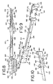
- FIG. 1 depicts a perspective view of a holder for an x-ray sensor and/or an x-ray film unit, in accordance with one preferred embodiment of the invention.
- FIG. 3 depicts an enlarged partial perspective view of a holder for an x-ray sensor and/or an x-ray film unit holding an x-ray film unit, in accordance with one preferred embodiment of the invention.
- FIG. 4 depicts side view of a holder for an x-ray sensor and/or an x-ray film unit holding an x-ray sensor, in accordance with one preferred embodiment of the invention.
- FIG. 5 depicts a perspective view an x-ray sensor, in accordance with one preferred embodiment of the invention.
- FIG. 6 depicts a top view a holder for an x-ray sensor and/or an x-ray film unit, in accordance with one preferred embodiment of the invention.
- FIG. 7 depicts a perspective view a holder for an x-ray sensor and/or an x-ray film unit, in accordance with one preferred embodiment of the invention.
- FIG. 8 depicts a top view a holder for an x-ray sensor and/or an x-ray film unit, in accordance with one preferred embodiment of the invention.
- FIG. 9 depicts a perspective view a holder for an x-ray sensor and/or an x-ray film unit, in accordance with one preferred embodiment of the invention.
- FIG. 10 depicts a partial perspective view a holder for an x-ray sensor and/or an x-ray film unit, in accordance with one preferred embodiment of the invention.
- FIG. 1 there is shown a perspective view of a holder 100 for an x-ray sensing device 120 , according to one preferred embodiment.
- the holder 100 is designed to hold and retain the x-ray sensing device 120 in a multitude of positions.
- the holder 100 is manufactured using an injection molded process in order to reduce costs.
- holder 100 can be manufactured in one of many ways.
- holder 100 may be machined, thermoformed, and hand-made.
- holder 100 is a one-piece unit which is integrally formed.
- holder 100 may comprise multiple parts which are then assembled and fitted together.
- holder 100 is constructed from a rigid yet somewhat flexible material, such as but not limited to: metals such as iron, steel, stainless steel, aluminum, silver, titanium, and brass; plastics, such as ethylene, vinyl, acetate; acrylics, such as acrylonitrol-butadine-styrene; resins; and polymers such as polycarbonate.
- the holder 100 may be colored any one of various different colors depending on the size and type of sensors used. For example, the holder may be colored white for a size two x-ray film unit or colored green for a size zero x-ray film unit.
- X-ray sensing device 120 is any device which can be used to sense radiation, and preferably x-ray radiation. As illustrated in FIGS. 1-5 , x-ray sensing device 120 includes such devices as an x-ray film unit 122 , which uses x-ray film 129 to detect x-rays, an x-ray sensor unit 124 , which uses a digital x-ray sensor 128 or a charge coupled device to detect x-rays, a phosphor imaging plate or the like. X-ray sensor unit 124 may include a wire 126 which is used to provide power and/or transfer signals between the digital x-ray sensor 128 and a control unit, not shown.
- x-ray sensing device 120 is a dental x-ray sensing device which is sized for use in the mouth of a patient in order to take x-ray scans of a patient's teeth.
- the holder 100 includes a first retention member 102 and a handle 106 connected with the first retention member 102 , as illustrated in FIGS. 1-3 .
- the first retention member 102 includes a back plate 140 , a first retention guide 142 , and a second retention guide 144 , as illustrated in FIGS. 1 , 7 , and 9 .
- the first retention guide 142 is connected with an end of the back plate 140 and the second retention guide is connected with an opposing end of the back plate 140 .
- the first retention guide 142 faces the second retention guide 144 .
- the back plate 140 , the first retention guide 142 , and the second retention guide 144 are integrally formed, as shown in FIGS. 1 , 7 , and 9 .
- each retention guide 142 , 144 forms a generally u-shaped cross section.
- each retention guide 142 , 144 forms a generally u-shaped cross section having a gripping portion 143 , 145 , respectively, wherein each gripping portion 143 , 145 curves inwards towards the back plate 140 , as illustrated in FIGS. 1 , 6 , 8 , and 9 .
- the gripping portions 143 , 145 help to better hold the x-ray sensing device 120 in place and allow the holder 100 to accommodate a wide variety of x-ray sensing devices with varying thicknesses, such as both x-ray film units 122 and x-ray sensor units 124 , as illustrated in FIGS. 1 and 8 , or such as x-ray sensor units of varying thicknesses.
- the gripping portions 143 , 145 are apply enough pressure on the x-ray sensing device 120 to hold the device 120 in place without damaging the device 120 .
- holder 100 can receive the x-ray sensing device 120 , by sliding the x-ray sensing device 120 in between the first retention guide 142 and the second retention guide 144 and against the back plate 140 , as illustrated in FIGS. 1-3 .
- each retention guide 142 , 144 are sized such that x-ray sensing device 120 fits firmly between the first retention guide 142 and the second retention guide 144 and against the back plate 140 , as illustrated in FIGS. 1 , 2 , 8 , and 9 .
- each retention guide 142 , 144 extends from an upper portion of the back plate 140 to a lower portion of the back plate 140 , as illustrated in FIGS. 4 and 9 .
- an upper portion of the back plate 140 is a portion of the back plate 140 that is within an upper half 158 of the back plate 140 and a lower portion of the back plate 140 is a portion of the back plate 140 that is within a lower half 159 of the back plate 140 .
- the retention stops 150 , 152 include a portion which extends away from the back plate 140 and allow for a user to position the x-ray sensing device 120 either towards the bottom portion of the back plate 140 , or towards the upper portion of the back plate 140 , as illustrated in FIGS. 2 and 7 .
- the holder 100 allows a user to position the x-ray sensing device 120 more accurately when x-ray either the upper or lower teeth in a patient's mouth.
- each retention stop 150 , 152 extends in a direction from the first retention guide 142 to the second retention guide 144 , as illustrated in FIG. 7 .
- the first retention member 102 includes flexible members 151 , 153 attached to each retention stop 150 , 152 , respectively, at one end and attached to the back plate 140 at a second end, as illustrated in FIG. 7 .
- the flexible members 151 , 153 may be formed in the back plate 140 , or may be formed on the back plate 140 , and allow the retention stops 150 , 152 to move back and forth upon insertion of an x-ray sensing device 120 into the first retention member 102 .
- the flexible members 151 , 153 also allow the retention stops 150 , 152 to apply an appropriate amount of pressure on the x-ray sensing device 120 , such that the x-ray sensing device 120 is held in place yet not damaged.
- the first retention member 102 includes more than one upper retention stop 150 , as illustrated in FIG. 7 . The additional retention stop 150 allows for better placement of the x-ray sensing device 120 .
- each retention guide 142 , 144 forms a retention groove 146 , 148 for receiving an x-ray film unit 122 , as illustrated in FIGS. 1 , 4 , and 6 , and 8 .
- the retention grooves 146 , 148 forms a u-shape cross section which is smaller than the u-shaped cross section formed by each retention guide 142 , 144 .
- the retention grooves 146 , 148 are better able to receive an x-ray film unit 122 , since generally, the x-ray film unit 122 has a smaller thickness T 2 than a thickness T 1 of the x-ray sensor unit 124 , as illustrated in FIG. 1 .
- a single retention member 102 , 104 is able to accommodate both an x-ray film unit 122 and an x-ray sensing device 120 , as illustrated in FIGS. 1 and 8 .
- the holder 100 includes a first wire retention member 108 on the handle 106 , as illustrated in FIG. 1 .
- Wire retention member 108 is able to accommodate and grasp a wire such as the wire 126 found in x-ray sensor unit 124 .
- the handle 106 also includes a groove 113 in which wire can reside in.
- groove 113 is able to accommodate and secure a wire such as the wire 126 found in x-ray sensor unit 124 , therefore preventing the wire from becoming tangled within a user's mouth.
- the wire retention member 108 is formed on the handle 106 adjacent the first retention member 102 .
- the holder 100 includes a second wire retention member 110 on the handle 106 , as illustrated in FIG. 1 .
- Wire retention member 110 is able to accommodate and grasp a wire such as the wire 126 found in x-ray sensor unit 124 .
- the handle 106 also includes a groove 111 in which wire can reside in.
- groove 111 is able to accommodate and secure a wire such as the wire 126 found in x-ray sensor unit 124 , therefore preventing the wire from becoming tangled within a user's mouth.
- the wire retention member 110 is formed on the handle 106 adjacent a second retention member 104 .
- the holder 100 comprises a bite block 130 on a back surface 174 of the back plate 160 , wherein the back surface 174 opposes a front surface 176 , as illustrated in FIGS. 1 and 8 .
- the bite block 130 is preferably positioned centrally on the back plate between the upper retention slot 170 and lower retention slot 172 as illustrated in FIG. 3 .
- the bite block 130 allows for more accurate positioning of the holder 100 , and more specifically the first retention member 102 and the sensor 120 , within a patient's mouth.
- the bite block 130 includes a series of serrations 132 , as illustrated in FIGS. 1 and 6 , in order to provide additional grip and less movement for the holder 100 within the patient's mouth.
- the serrations 132 are diamond shaped and are indented into the bite block.
- the length L from one end of the holder 100 to another end of the holder 100 in a direction from a first retention member to a second retention member 104 is approximately between 5 and 50 centimeters and more preferably between 10 and 30 centimeters and most preferably between 15 and 25 centimeters. Additionally, the distance D 1 between a first retention groove 146 and a second retention groove 148 is preferably between 3 and 8 centimeters. Additionally, a distance D 2 between a first retention guide 142 and a second retention guide 144 , as illustrated in FIG. 6 , is preferably between 3 and 8 centimeters.
- a distance D 3 between the back plate 140 and a far end of a retention guide 142 , 144 , as illustrated in FIG. 6 is preferably between 1 and 20 millimeters, and more preferably, between 2 to 10 millimeters, and a distance D 4 between one end of the retention groove and a second end of the retention groove, as illustrated in FIG. 6 , is approximately between 0.1 and 4 millimeters, and more preferably, between 0.5 and 3 millimeters.
- a distance D 5 from the back surface of the back plate 140 to a distal surface of the bite block 130 , as illustrated in FIG. 6 is preferably between 1 and 3 centimeters.
- the holder 100 includes a pivoting member 182 attached to the back plate 140 of the first retention member 102 at a pivot point 180 and connected with the handle 106 , as illustrated in FIG. 10 .
- the pivoting member 182 allows the first retention member 102 to be pivoted at the pivot point 180 , thus providing the holder 100 with the ability to rotate the retention member 102 at a variety of angles with respect to the handle 106 .
- the pivoting member 182 also provides the user with a variety of configurations in which the holder may be placed, and therefore provides the user with additional flexibility when positioning the holder 100 , and more specifically, the retention member 102 .
- the back plate 140 includes a series of stops 184 projecting radially outwards from the pivot point 180 .
- the stops 184 may either be in the form of grooves formed in the back surface 156 or in the form of projections formed on the back surface 156 .
- the stops 184 engage the pivoting member 182 and stop the pivoting member 182 from pivoting at preselected angles with respect to the handle 106 , as illustrated in FIG. 10 .
Landscapes
- Physics & Mathematics (AREA)
- General Physics & Mathematics (AREA)
- Health & Medical Sciences (AREA)
- General Health & Medical Sciences (AREA)
- Oral & Maxillofacial Surgery (AREA)
- Engineering & Computer Science (AREA)
- Microelectronics & Electronic Packaging (AREA)
- Apparatus For Radiation Diagnosis (AREA)
Abstract
A holder for an x-ray sensing device having a first retention member and a handle. The first retention member includes a back plate, a first retention guide, and a second retention guide. The first retention guide is connected with an end of the back plate and the second retention guide connected with an opposing end of the back plate. The first retention guide faces the second retention guide. The handle is connected with the first retention member. Preferably, the first retention member includes a retention stop on a front surface of the back plate and between the retention guides.
Description
This continuation application claims the benefit and priority of U.S. patent application Ser. No. 10/985,381, filed Nov. 11, 2004 now U.S. Pat. No. 7,226,208, which is incorporated by reference in its entirety.
This invention relates generally to sensor holders, and in particular, to a holder for a dental x-ray sensing device.
Dental radiographs are made using x-ray examination units, often including an x-ray cone or tube positioned proximate the patient and aligned to take x-rays of certain teeth. Dental x-ray sensing devices, which include including x-ray film units, digital x-ray sensors, charge coupled devices, phosphor imaging plates or the like, often have a generally flat or plate-like configuration and standardized dimensions so that the sensing device can be placed into the oral cavity.
The sensing device is placed into the patient's mouth and held in place proximate to the tooth or teeth to be examined. The x-ray's are directed through the target teeth and then through the sensor. It has been found that proper orientation of the sensor is required to eliminate distortions and improper focus.
To ensure proper orientation of the sensing device, sensor carriers or holders with “bite blocks” have been developed. These devices often have a plate for holding the sensing device and a bite block that the patient bites down upon to position the device and the carried sensor. A bite block is shown for example, in U.S. Pat. No. 3,473,026.
Different sensing devices are often used depending upon the area of the mouth to be examined. This may include for example, endo, posterior, anterior, left, right, upper and lower bite wings, and the like. Known bite blocks and sensor holders have been individually designed and manufactured for each different type of sensing device. The dimensions of the sensing device and the holder dictate the degree of secured positioning of the sensing device in the holder.
A dental professional may have a large number of x-ray sensing devices with varying sizes and shapes, and hence, a similarly large number of sensor holders. The dental professional is often faced with employing a different sensing device or set of sensing devices, holders and bite blocks depending upon the particular x-ray procedure being employed and the area of the mouth to be examined. At best, it is time consuming to change between sensing devices, sensor holders and bite blocks.
Additionally, some of the known sensor holders are fairly complex in design, and therefore may be relatively costly to manufacture, see for example U.S. Pat. No. 4,965,885. Since some of the sensor holders may not be inexpensive, they must be reused instead of disposed of. In order to reuse the holders, they typically need to be decontaminated and sterilized, or covered, every time they are inserted into a patient's mouth, which can be a rather cumbersome procedure.
Many of the sensor holders were designed for use with x-ray film units, which are more robust, and therefore they may damage a digital x-ray sensor, which is more fragile. Since the digital x-ray sensors can be relatively expensive, much care must be used when using them with many of the current sensor holders.
A need exists therefore, for a sensor holder which can accommodate different sizes and shapes of sensing devices. It has also been found that a need exits for a sensor holder which can hold a sensing device in a variety of positions so that different areas of the mouth may be examined using only one sensor holder. A need also exists for a sensor holder which can be manufactured at a lower cost, thus allowing the user to dispose of the holder. Additionally, a need exists for an improved sensor holder which prevents damage to digital x-ray sensors.
The present invention is defined by the following claims, and nothing in this section should be taken as a limitation on those claims. By way of introduction, the preferred embodiments described below relate to a holder for an x-ray sensing device having a first retention member and a handle. The first retention member includes a back plate, a first retention guide, and a second retention guide. The first retention guide is connected with an end of the back plate and the second retention guide connected with an opposing end of the back plate. The first retention guide faces the second retention guide. The handle is connected with the first retention member. Preferably, the first retention member includes a retention stop on a front surface of the back plate and between the retention guides.
The preferred embodiments further relate to a holder for an x-ray sensing device having a handle, a first retention member, and a second retention member. The first retention member includes a first back plate, a first retention guide connected with an end of the first back plate and a second retention guide connected with an opposing end of the first back plate. The first retention guide faces to the second retention guide. The second retention member includes a second back plate, a third retention guide connected with an end of the second back plate and a fourth retention guide connected with an opposing end of the second back plate. The third retention guide faces to the fourth retention guide. The first retention member is connected with one end of the handle and the second retention member is connected with an opposing end of the handle.
The preferred embodiments further relate to a holder for an x-ray sensing device having a handle and a retention member. The retention member includes a back plate, a first retention guide connected with an end of the back plate and a second retention guide connected with an opposing end of the back plate. The first retention guide faces to the second retention guide. Each retention guide forms a generally u-shaped cross-section for receiving an x-ray sensor unit and a retention groove for receiving an x-ray film unit.
It should be appreciated that for simplicity and clarity of illustration, elements shown in the Figures have not necessarily been drawn to scale. For example, the dimensions of some of the elements are exaggerated relative to each other for clarity. Further, where considered appropriate, reference numerals have been repeated among the Figures to indicate corresponding elements.
Referring to FIG. 1 , there is shown a perspective view of a holder 100 for an x-ray sensing device 120, according to one preferred embodiment. The holder 100 is designed to hold and retain the x-ray sensing device 120 in a multitude of positions. Preferably, the holder 100 is manufactured using an injection molded process in order to reduce costs. However, holder 100 can be manufactured in one of many ways. For example, holder 100 may be machined, thermoformed, and hand-made. Preferably, in order to reduce costs and maintain rigidity, holder 100 is a one-piece unit which is integrally formed. However, holder 100 may comprise multiple parts which are then assembled and fitted together. Preferably, holder 100 is constructed from a rigid yet somewhat flexible material, such as but not limited to: metals such as iron, steel, stainless steel, aluminum, silver, titanium, and brass; plastics, such as ethylene, vinyl, acetate; acrylics, such as acrylonitrol-butadine-styrene; resins; and polymers such as polycarbonate. The holder 100 may be colored any one of various different colors depending on the size and type of sensors used. For example, the holder may be colored white for a size two x-ray film unit or colored green for a size zero x-ray film unit.
The holder 100 includes a first retention member 102 and a handle 106 connected with the first retention member 102, as illustrated in FIGS. 1-3 . The first retention member 102 includes a back plate 140, a first retention guide 142, and a second retention guide 144, as illustrated in FIGS. 1 , 7, and 9. The first retention guide 142 is connected with an end of the back plate 140 and the second retention guide is connected with an opposing end of the back plate 140. The first retention guide 142 faces the second retention guide 144. Preferably, the back plate 140, the first retention guide 142, and the second retention guide 144 are integrally formed, as shown in FIGS. 1 , 7, and 9. Preferably, each retention guide 142, 144 forms a generally u-shaped cross section.
More preferably, each retention guide 142, 144 forms a generally u-shaped cross section having a gripping portion 143, 145, respectively, wherein each gripping portion 143, 145 curves inwards towards the back plate 140, as illustrated in FIGS. 1 , 6, 8, and 9. The gripping portions 143, 145 help to better hold the x-ray sensing device 120 in place and allow the holder 100 to accommodate a wide variety of x-ray sensing devices with varying thicknesses, such as both x-ray film units 122 and x-ray sensor units 124, as illustrated in FIGS. 1 and 8 , or such as x-ray sensor units of varying thicknesses. Preferably, the gripping portions 143, 145 are apply enough pressure on the x-ray sensing device 120 to hold the device 120 in place without damaging the device 120. With this configuration, holder 100 can receive the x-ray sensing device 120, by sliding the x-ray sensing device 120 in between the first retention guide 142 and the second retention guide 144 and against the back plate 140, as illustrated in FIGS. 1-3 .
Preferably the retention guides 142, 144 are sized such that x-ray sensing device 120 fits firmly between the first retention guide 142 and the second retention guide 144 and against the back plate 140, as illustrated in FIGS. 1 , 2, 8, and 9. Preferably each retention guide 142, 144 extends from an upper portion of the back plate 140 to a lower portion of the back plate 140, as illustrated in FIGS. 4 and 9 . As defined herein, an upper portion of the back plate 140 is a portion of the back plate 140 that is within an upper half 158 of the back plate 140 and a lower portion of the back plate 140 is a portion of the back plate 140 that is within a lower half 159 of the back plate 140. Dividing the back plate 140 into two halves, wherein each half extends from the first retention guide 142 to the second retention guide 144, one half is the upper half 158 and the opposing half is the lower half 159, as illustrated in FIGS. 4 and 9 , wherein the back plate 140 is divided into halves by imaginary line 1-1 located centrally in back plate 140.
In one embodiment the first retention member 102 includes a retention stop, such as an upper retention stop 150, on a front surface 154 of the back plate 140. The retention stop is preferably between the retention guides 142, 144, as illustrated in FIGS. 6-9 . Preferably the first retention member 102 comprises an upper retention stop 150 connected with an upper portion of the back plate 140, and a lower retention stop 152 opposed to the upper retention stop 150 and connected with a lower portion of the back plate 140. Preferably both the upper and lower retention stops, 150, 152 are located between the retention guides 142, 144. The retention stops 150, 152 include a portion which extends away from the back plate 140 and allow for a user to position the x-ray sensing device 120 either towards the bottom portion of the back plate 140, or towards the upper portion of the back plate 140, as illustrated in FIGS. 2 and 7 . By allowing a user to change the position of the x-ray sensing device 120 in this way, the holder 100 allows a user to position the x-ray sensing device 120 more accurately when x-ray either the upper or lower teeth in a patient's mouth. Preferably, each retention stop 150, 152 extends in a direction from the first retention guide 142 to the second retention guide 144, as illustrated in FIG. 7 .
Preferably, the first retention member 102 includes flexible members 151, 153 attached to each retention stop 150, 152, respectively, at one end and attached to the back plate 140 at a second end, as illustrated in FIG. 7 . The flexible members 151, 153 may be formed in the back plate 140, or may be formed on the back plate 140, and allow the retention stops 150, 152 to move back and forth upon insertion of an x-ray sensing device 120 into the first retention member 102. Additionally, by allowing the retention stops 150, 152 to move back and forth, the flexible members 151, 153 also allow the retention stops 150, 152 to apply an appropriate amount of pressure on the x-ray sensing device 120, such that the x-ray sensing device 120 is held in place yet not damaged. In one embodiment, the first retention member 102 includes more than one upper retention stop 150, as illustrated in FIG. 7 . The additional retention stop 150 allows for better placement of the x-ray sensing device 120.
In one embodiment, each retention guide 142, 144 forms a retention groove 146, 148 for receiving an x-ray film unit 122, as illustrated in FIGS. 1 , 4, and 6, and 8. The retention grooves 146, 148 forms a u-shape cross section which is smaller than the u-shaped cross section formed by each retention guide 142, 144. By forming a smaller u-shaped cross section, the retention grooves 146, 148 are better able to receive an x-ray film unit 122, since generally, the x-ray film unit 122 has a smaller thickness T2 than a thickness T1 of the x-ray sensor unit 124, as illustrated in FIG. 1 . In this manner by using retention grooves 146 and 148, a single retention member 102, 104 is able to accommodate both an x-ray film unit 122 and an x-ray sensing device 120, as illustrated in FIGS. 1 and 8 .
In one embodiment, the holder 100 includes a first wire retention member 108 on the handle 106, as illustrated in FIG. 1 . Wire retention member 108 is able to accommodate and grasp a wire such as the wire 126 found in x-ray sensor unit 124. Preferably, the handle 106 also includes a groove 113 in which wire can reside in. Working in conjunction with wire retention member 108, groove 113 is able to accommodate and secure a wire such as the wire 126 found in x-ray sensor unit 124, therefore preventing the wire from becoming tangled within a user's mouth. Preferably, the wire retention member 108 is formed on the handle 106 adjacent the first retention member 102.
In one embodiment, the holder 100 includes a second wire retention member 110 on the handle 106, as illustrated in FIG. 1 . Wire retention member 110 is able to accommodate and grasp a wire such as the wire 126 found in x-ray sensor unit 124. Preferably, the handle 106 also includes a groove 111 in which wire can reside in. Working in conjunction with wire retention member 110, groove 111 is able to accommodate and secure a wire such as the wire 126 found in x-ray sensor unit 124, therefore preventing the wire from becoming tangled within a user's mouth. Preferably, the wire retention member 110 is formed on the handle 106 adjacent a second retention member 104.
In one embodiment, the holder 100 includes a second retention member 104 connected with the handle 106, wherein the second retention member 104 is opposed to the first retention member 102. The second retention member 104 functions essentially the same way as the first retention member 102 and may include many of the same elements as found in the first retention member 102. In one embodiment, the second retention member 104 includes a back plate 160, retention guides 162, 164, gripping portions 163, 165, retention grooves 166, 168, an upper retention stop 170, and a lower retention stop 172, as illustrated in FIGS. 1 , 3, and 6-9. Preferably, the first retention member 102 is connected with one end of the handle 106 and the second retention member 104 is connected with an opposing end of the handle 106 as illustrated in FIG. 1 . Preferably, the first and second retention members 102, 104 are each sized differently so that each retention member 102, 104 can accept an x-ray sensing device 120 of a different size. For example, in one embodiment the first retention member 102 may be sized to accept a first x-ray sensing device 120 and a second retention member 104 may be sized to accept a second x-ray sensing device 120, wherein the size of the first x-ray sensing device 120 is not equal to the size of the second x-ray sensing device 120.
In one embodiment, the holder 100 comprises a bite block 130 on a back surface 174 of the back plate 160, wherein the back surface 174 opposes a front surface 176, as illustrated in FIGS. 1 and 8 . The bite block 130 is preferably positioned centrally on the back plate between the upper retention slot 170 and lower retention slot 172 as illustrated in FIG. 3 . When the holder 100 is inserted into a patient's mouth, the patient is able to bite down with the patient's teeth on the bite block 130 and engage the first retention member 102. The bite block 130 allows for more accurate positioning of the holder 100, and more specifically the first retention member 102 and the sensor 120, within a patient's mouth. Preferably, the bite block 130 includes a series of serrations 132, as illustrated in FIGS. 1 and 6 , in order to provide additional grip and less movement for the holder 100 within the patient's mouth. Preferably, the serrations 132 are diamond shaped and are indented into the bite block.
As illustrated in FIG. 6 , the length L from one end of the holder 100 to another end of the holder 100 in a direction from a first retention member to a second retention member 104, is approximately between 5 and 50 centimeters and more preferably between 10 and 30 centimeters and most preferably between 15 and 25 centimeters. Additionally, the distance D1 between a first retention groove 146 and a second retention groove 148 is preferably between 3 and 8 centimeters. Additionally, a distance D2 between a first retention guide 142 and a second retention guide 144, as illustrated in FIG. 6 , is preferably between 3 and 8 centimeters. A distance D3 between the back plate 140 and a far end of a retention guide 142, 144, as illustrated in FIG. 6 , is preferably between 1 and 20 millimeters, and more preferably, between 2 to 10 millimeters, and a distance D4 between one end of the retention groove and a second end of the retention groove, as illustrated in FIG. 6 , is approximately between 0.1 and 4 millimeters, and more preferably, between 0.5 and 3 millimeters. A distance D5 from the back surface of the back plate 140 to a distal surface of the bite block 130, as illustrated in FIG. 6 , is preferably between 1 and 3 centimeters.
In one embodiment, the holder 100 includes a pivoting member 182 attached to the back plate 140 of the first retention member 102 at a pivot point 180 and connected with the handle 106, as illustrated in FIG. 10 . The pivoting member 182 allows the first retention member 102 to be pivoted at the pivot point 180, thus providing the holder 100 with the ability to rotate the retention member 102 at a variety of angles with respect to the handle 106. The pivoting member 182 also provides the user with a variety of configurations in which the holder may be placed, and therefore provides the user with additional flexibility when positioning the holder 100, and more specifically, the retention member 102. Preferably, the back plate 140 includes a series of stops 184 projecting radially outwards from the pivot point 180. The stops 184 may either be in the form of grooves formed in the back surface 156 or in the form of projections formed on the back surface 156. The stops 184 engage the pivoting member 182 and stop the pivoting member 182 from pivoting at preselected angles with respect to the handle 106, as illustrated in FIG. 10 .
Although the invention has been described and illustrated with reference to specific illustrative embodiments thereof, it is not intended that the invention be limited to those illustrative embodiments. Those skilled in the art will recognize that variations and modifications can be made without departing from the spirit of the invention.
Claims (13)
1. A holder for an x-ray sensing device having a retention member, the retention member comprising:
a back plate;
a first retention guide connected with a first end of the back plate;
a second retention guide connected with a second end of the back plate opposed to the first end, wherein the first retention guide faces the second retention guide; and
an upper retention stop connected with the back plate and between the retention guides, wherein the retention member is configured to hold the x-ray sensing device in a central position between the first and second retention guides and against the upper retention stop, and configured to hold the x-ray sensing device in a lower position wherein a top edge of the x-ray sensing device abuts the upper retention stop.
2. The holder for an x-ray sensing device of claim 1 , wherein the x-ray sensing device is movable from the central position to the upper position.
3. The holder for an x-ray sensing device of claim 1 , wherein the x-ray sensing device is movable from the central position to the upper position without having to remove the x-ray sensing device from the holder.
4. The holder for an x-ray sensing device of claim 1 , wherein the upper retention stop is opposed to a lower retention stop, and wherein the upper and lower retention stops are located between the retention guides.
5. The holder for an x-ray sensing device of claim 4 , wherein the retention member is configured to hold the x-ray sensing device in an upper position wherein a bottom edge of the x-ray sensing device abuts the lower retention stop.
6. The holder for an x-ray sensing device of claim 1 further comprising a flexible member attached to the upper retention stop at a first end and to the back plate at a second end.
7. The holder for an x-ray sensing device of claim 1 , wherein each retention guide only extends from an upper portion of the back plate to a lower portion of the back plate.
8. A holder for an x-ray sensing device having a retention member, the retention member comprising:
a back plate;
a first retention guide connected with a first end of the back plate; and
a second retention guide connected with a second end of the back plate opposed to the first end, wherein the first retention guide faces the second retention guide, wherein the first retention guide includes a gripping portion which curves inwards towards the back plate, wherein the retention member is configured to receive the x-ray sensing device by sliding the x-ray sensing device in between the first and second retention guides and against the back plate, wherein the gripping portion is moveable from a first position which is closest to the back plate and a second position which is further away from the back plate than the first position, and wherein the gripping portion is pivotable at where the gripping portion curves inwards.
9. The holder for an x-ray sensing device of claim 8 , wherein the first retention guide forms a bend from which the gripping portion extend.
10. The holder for an x-ray sensing device of claim 9 , wherein the gripping portion extends in a generally linear direction from the bend.
11. The holder for an x-ray sensing device of claim 8 further comprising upper and lower retention stops located between the retention guides.
12. The holder for an x-ray sensing device of claim 8 further comprising a wire retention member on a handle connected with the retention member.
13. The holder for an x-ray sensing device of claim 8 , wherein each retention guide only extends from an upper portion of the back plate to a lower portion of the back plate.
Priority Applications (1)
| Application Number | Priority Date | Filing Date | Title |
|---|---|---|---|
| US11/751,354 US7607830B2 (en) | 2004-11-11 | 2007-05-21 | Holder for an x-ray sensing device |
Applications Claiming Priority (2)
| Application Number | Priority Date | Filing Date | Title |
|---|---|---|---|
| US10/985,381 US7226208B2 (en) | 2004-11-11 | 2004-11-11 | Holder for an x-ray sensing device |
| US11/751,354 US7607830B2 (en) | 2004-11-11 | 2007-05-21 | Holder for an x-ray sensing device |
Related Parent Applications (1)
| Application Number | Title | Priority Date | Filing Date |
|---|---|---|---|
| US10/985,381 Continuation US7226208B2 (en) | 2004-11-11 | 2004-11-11 | Holder for an x-ray sensing device |
Publications (2)
| Publication Number | Publication Date |
|---|---|
| US20080025468A1 US20080025468A1 (en) | 2008-01-31 |
| US7607830B2 true US7607830B2 (en) | 2009-10-27 |
Family
ID=36316340
Family Applications (3)
| Application Number | Title | Priority Date | Filing Date |
|---|---|---|---|
| US10/985,381 Active US7226208B2 (en) | 2004-11-11 | 2004-11-11 | Holder for an x-ray sensing device |
| US11/742,947 Active US7607831B2 (en) | 2004-11-11 | 2007-05-01 | Ring guide adapter |
| US11/751,354 Active 2024-11-24 US7607830B2 (en) | 2004-11-11 | 2007-05-21 | Holder for an x-ray sensing device |
Family Applications Before (2)
| Application Number | Title | Priority Date | Filing Date |
|---|---|---|---|
| US10/985,381 Active US7226208B2 (en) | 2004-11-11 | 2004-11-11 | Holder for an x-ray sensing device |
| US11/742,947 Active US7607831B2 (en) | 2004-11-11 | 2007-05-01 | Ring guide adapter |
Country Status (2)
| Country | Link |
|---|---|
| US (3) | US7226208B2 (en) |
| WO (1) | WO2006053174A1 (en) |
Cited By (5)
| Publication number | Priority date | Publication date | Assignee | Title |
|---|---|---|---|---|
| US9247916B2 (en) | 2014-01-09 | 2016-02-02 | Anita Tomkoria | Sensor holding apparatus for facilitating dental imaging |
| USD750255S1 (en) | 2014-03-26 | 2016-02-23 | Harold K. Schmulenson | Bite wing of a radiation sensing device holder |
| USD762856S1 (en) | 2012-07-20 | 2016-08-02 | Dentsply International Inc. | Adjustable dental media holder |
| US9901313B2 (en) | 2014-03-26 | 2018-02-27 | Harold K. Schmulenson | Sensor holder for x-ray radiation sensing device |
| US10327719B2 (en) | 2014-01-09 | 2019-06-25 | Anita Tomkoria | Sensor holding apparatus for facilitating dental imaging |
Families Citing this family (17)
| Publication number | Priority date | Publication date | Assignee | Title |
|---|---|---|---|---|
| US7226208B2 (en) * | 2004-11-11 | 2007-06-05 | Schmulenson Harold K | Holder for an x-ray sensing device |
| JP5334578B2 (en) | 2005-08-16 | 2013-11-06 | デンツプライ インターナショナル インコーポレーテッド | Dental X-ray digital sensor holder |
| US7425095B2 (en) * | 2005-08-23 | 2008-09-16 | Harold K. Schmulenson | Instrument for holding and aligning an x-ray sensing device |
| US7819579B2 (en) * | 2007-11-26 | 2010-10-26 | Schmulenson Harold K | Radiation sensing device and holder |
| US8142074B2 (en) | 2007-11-26 | 2012-03-27 | Schmulenson Harold K | Radiation sensing device and holder |
| FR2927525B1 (en) * | 2008-02-19 | 2011-04-15 | Owandy | DENTAL RADIOGRAPHY DEVICE AND X-RAY SENSOR |
| US8333507B2 (en) * | 2008-12-29 | 2012-12-18 | Schmulenson Harold K | Holder for radiation sensing device |
| US8031838B2 (en) | 2009-01-29 | 2011-10-04 | The Invention Science Fund I, Llc | Diagnostic delivery service |
| US8130904B2 (en) | 2009-01-29 | 2012-03-06 | The Invention Science Fund I, Llc | Diagnostic delivery service |
| US8057096B2 (en) * | 2009-07-08 | 2011-11-15 | Churchill Scott P | Dental radiograph sensor positioning device |
| US8500328B2 (en) | 2010-02-25 | 2013-08-06 | Proedge Dental Products, Inc. | Dental sensor holder and method of holding a dental sensor |
| US20130089185A1 (en) * | 2011-10-07 | 2013-04-11 | William Winters | Dental x-ray receptor positioning device |
| US9314215B2 (en) | 2012-08-22 | 2016-04-19 | Sirona Dental, Inc. | Dental positioning system |
| US20140270068A1 (en) * | 2013-03-15 | 2014-09-18 | Zuma Dental, LLC | Imaging system and method |
| US11191497B2 (en) * | 2018-10-16 | 2021-12-07 | Shayda Cullen | Digital dental x-ray sensor device having a rounded housing including a radio transceiver |
| US10506992B1 (en) * | 2018-10-16 | 2019-12-17 | Shayda Cullen | Digital dental x-ray sensor device having a rounded housing |
| USD961773S1 (en) * | 2020-09-01 | 2022-08-23 | Dentsply Sirona Inc. | Dental sensor |
Citations (52)
| Publication number | Priority date | Publication date | Assignee | Title |
|---|---|---|---|---|
| US1434894A (en) | 1921-05-10 | 1922-11-07 | Lee Andrew J Hawkins | Holder for dental x-ray films |
| US1557796A (en) | 1923-11-23 | 1925-10-20 | William A Bonar | Dental film support |
| US1706117A (en) | 1928-04-21 | 1929-03-19 | Jacob G Heckel | Dental X-ray-film holder |
| US2005993A (en) | 1934-05-15 | 1935-06-25 | Donald D Heron | Holder for dental x-ray films |
| US2075491A (en) | 1933-10-19 | 1937-03-30 | Wilson William Everett | Dental x-ray film holder |
| US2090933A (en) | 1933-05-05 | 1937-08-24 | Leonard M Bolin | Device for positioning dental X-ray films |
| US2239569A (en) | 1939-12-29 | 1941-04-22 | James B Poindexter | Dental x-ray film holder |
| US2240336A (en) | 1940-08-14 | 1941-04-29 | Raymond L Kreider | Dental x-ray film holder |
| US3304422A (en) | 1964-07-30 | 1967-02-14 | Prec X Ray Company | Dental X-ray shield and film holding support having a bite-receiving member |
| US3356845A (en) | 1965-03-30 | 1967-12-05 | Bergendal Gunnar | Dental X-ray film holder with plural grooves opening in opposite directions to support X-ray films |
| US3473026A (en) | 1966-09-21 | 1969-10-14 | William J Updegrave | Dental instruments for standardizing the bisecting-angle technique for periapical radiography |
| US4075494A (en) | 1976-11-29 | 1978-02-21 | Jermyn Arthur C | Orally receptive holder for a dental x-ray film paquette |
| US4150296A (en) | 1976-09-07 | 1979-04-17 | Gunnar Edeland | Device in connection with X-ray apparatus for dental use |
| US4251732A (en) | 1979-08-20 | 1981-02-17 | Fried Alan J | Dental x-ray film holders |
| US4295050A (en) | 1979-02-27 | 1981-10-13 | Sigurd Linden | Instrument for positioning an X-ray camera in dental X-ray photography |
| US4365162A (en) | 1979-03-09 | 1982-12-21 | Sven Jarby | Device for holding X-ray-sensitive films for odontological radiographs |
| US4484342A (en) | 1983-02-14 | 1984-11-20 | Xerox Corporation | Endodontic holder |
| US4489427A (en) | 1983-02-14 | 1984-12-18 | Xerox Corporation | Bitewing holder |
| US4554676A (en) | 1983-03-16 | 1985-11-19 | The S. S. White Company | Dental aiming device |
| DE8701308U1 (en) | 1987-01-28 | 1987-03-12 | Fuhrmann, Andreas, Dr.Med.Dent., 2000 Hamburg, De | |
| US4707847A (en) | 1983-06-15 | 1987-11-17 | 501 Hecopharma B.V. | Device for taking a picture of a jaw part |
| US4815117A (en) | 1987-09-02 | 1989-03-21 | Waldo Patricia J | Cushioning bite plate adapter for x-ray film holder |
| US4866750A (en) | 1987-03-27 | 1989-09-12 | Board Of Regents, The University Of Texas System | Image receptor holder and bite block device |
| US4945553A (en) | 1989-04-10 | 1990-07-31 | Willis Timothy G | Intra-oral radiographic film holder |
| US4949370A (en) | 1987-09-16 | 1990-08-14 | Nix Company Limited | Dental X-ray irradiation indicating device |
| US5022065A (en) | 1988-11-24 | 1991-06-04 | Wijkstroem Karin | X-ray film holder |
| US5044009A (en) | 1989-05-10 | 1991-08-27 | Klauser Rolf M | Set of x-ray film holders for taking X-ray exposures of an entire tooth |
| US5090047A (en) | 1990-10-23 | 1992-02-18 | Applied Research Company | Apparatus for reproducibly positioning an image receptor for intraoral diagnostics |
| US5289522A (en) | 1992-11-16 | 1994-02-22 | Kanbar Maurice S | Dental X-ray aiming device |
| US5327477A (en) | 1992-12-29 | 1994-07-05 | Paul Levy | Film positioning system for dental X-ray procedures |
| US5473662A (en) | 1994-08-15 | 1995-12-05 | Barish; Elliott M. | Radiographic instrument for osseointegration implant |
| US5625666A (en) | 1995-11-29 | 1997-04-29 | Willis; Timothy G. | Radiographic film retaining device |
| US5629972A (en) | 1993-05-18 | 1997-05-13 | Research Foundation Of State University Of New York | Intraoral radiograph alignment device |
| US5652779A (en) | 1995-09-01 | 1997-07-29 | Paul Levy | Film positioning system for dental X-ray procedures |
| US5677537A (en) * | 1995-04-05 | 1997-10-14 | Pfeiffer; Manfred | Device for recording images in the oral cavity especially for dental diagnosis |
| US5737388A (en) | 1994-03-03 | 1998-04-07 | Kossila; Pauli Juhani | Digital intraoral X-ray photography method and holder for picture plate or X-ray film |
| US6033111A (en) | 1998-11-20 | 2000-03-07 | Wolf X-Ray Corporation | Color coding method and apparatus for an X-ray positioning system |
| US6102566A (en) | 1998-11-10 | 2000-08-15 | Willis; Timothy G. | Oscillatory guide for X-Ray cone |
| US6190042B1 (en) | 1998-09-29 | 2001-02-20 | Electro Medical Systems | Dental x-ray aiming device for longitudinal radiographic analysis |
| US6343875B1 (en) | 1999-06-30 | 2002-02-05 | Dentsply Research & Development Corp. | Modular bite block and sensor holder apparatus for dental x-ray procedures |
| US20020106057A1 (en) * | 1999-10-21 | 2002-08-08 | Halpert Daniel H. | Dental x-ray block |
| US6461038B2 (en) | 2000-12-18 | 2002-10-08 | Richard R. Pellegrini | Dental X-ray sensor holder |
| US6540399B1 (en) | 1999-02-26 | 2003-04-01 | Dentsply Research & Development Corp. | Bite block for dental X-Ray procedures |
| US6592256B2 (en) | 2001-05-10 | 2003-07-15 | Hawe Neos Dental Sa | Film holder for dental technique |
| US20030185347A1 (en) | 2002-04-01 | 2003-10-02 | Diederich Jennifer A. | Intraoral dental radiology positioning device |
| US20040028187A1 (en) | 2002-04-01 | 2004-02-12 | Diederich Jennifer A. | Intraoral dental radiology positioning device |
| US20040170253A1 (en) | 2002-11-27 | 2004-09-02 | Op-D-Op, Inc. | Apparatus for retaining a radiographic sensor during dental x-ray imaging |
| US20050013412A1 (en) | 2003-07-17 | 2005-01-20 | Calderwood Mitchell C. | Radiographic sensor positioning system |
| US20050047550A1 (en) | 2003-09-03 | 2005-03-03 | Yin-Chao Yao | Dental X-ray clamping device with a multi-orientation support |
| US6905244B2 (en) | 2002-09-30 | 2005-06-14 | Kerrhawe Sa | Holder for digital sensors for dentistry |
| US20060188070A1 (en) | 2005-02-23 | 2006-08-24 | Razzano Michael R | Image capture device and methods |
| US7226208B2 (en) * | 2004-11-11 | 2007-06-05 | Schmulenson Harold K | Holder for an x-ray sensing device |
-
2004
- 2004-11-11 US US10/985,381 patent/US7226208B2/en active Active
-
2005
- 2005-11-10 WO PCT/US2005/040854 patent/WO2006053174A1/en active Application Filing
-
2007
- 2007-05-01 US US11/742,947 patent/US7607831B2/en active Active
- 2007-05-21 US US11/751,354 patent/US7607830B2/en active Active
Patent Citations (58)
| Publication number | Priority date | Publication date | Assignee | Title |
|---|---|---|---|---|
| US1434894A (en) | 1921-05-10 | 1922-11-07 | Lee Andrew J Hawkins | Holder for dental x-ray films |
| US1557796A (en) | 1923-11-23 | 1925-10-20 | William A Bonar | Dental film support |
| US1706117A (en) | 1928-04-21 | 1929-03-19 | Jacob G Heckel | Dental X-ray-film holder |
| US2090933A (en) | 1933-05-05 | 1937-08-24 | Leonard M Bolin | Device for positioning dental X-ray films |
| US2075491A (en) | 1933-10-19 | 1937-03-30 | Wilson William Everett | Dental x-ray film holder |
| US2005993A (en) | 1934-05-15 | 1935-06-25 | Donald D Heron | Holder for dental x-ray films |
| US2239569A (en) | 1939-12-29 | 1941-04-22 | James B Poindexter | Dental x-ray film holder |
| US2240336A (en) | 1940-08-14 | 1941-04-29 | Raymond L Kreider | Dental x-ray film holder |
| US3304422A (en) | 1964-07-30 | 1967-02-14 | Prec X Ray Company | Dental X-ray shield and film holding support having a bite-receiving member |
| US3356845A (en) | 1965-03-30 | 1967-12-05 | Bergendal Gunnar | Dental X-ray film holder with plural grooves opening in opposite directions to support X-ray films |
| US3473026A (en) | 1966-09-21 | 1969-10-14 | William J Updegrave | Dental instruments for standardizing the bisecting-angle technique for periapical radiography |
| US4150296A (en) | 1976-09-07 | 1979-04-17 | Gunnar Edeland | Device in connection with X-ray apparatus for dental use |
| US4075494A (en) | 1976-11-29 | 1978-02-21 | Jermyn Arthur C | Orally receptive holder for a dental x-ray film paquette |
| US4295050A (en) | 1979-02-27 | 1981-10-13 | Sigurd Linden | Instrument for positioning an X-ray camera in dental X-ray photography |
| US4365162A (en) | 1979-03-09 | 1982-12-21 | Sven Jarby | Device for holding X-ray-sensitive films for odontological radiographs |
| US4251732A (en) | 1979-08-20 | 1981-02-17 | Fried Alan J | Dental x-ray film holders |
| US4484342A (en) | 1983-02-14 | 1984-11-20 | Xerox Corporation | Endodontic holder |
| US4489427A (en) | 1983-02-14 | 1984-12-18 | Xerox Corporation | Bitewing holder |
| US4554676A (en) | 1983-03-16 | 1985-11-19 | The S. S. White Company | Dental aiming device |
| US4707847A (en) | 1983-06-15 | 1987-11-17 | 501 Hecopharma B.V. | Device for taking a picture of a jaw part |
| DE8701308U1 (en) | 1987-01-28 | 1987-03-12 | Fuhrmann, Andreas, Dr.Med.Dent., 2000 Hamburg, De | |
| US4965885A (en) | 1987-01-28 | 1990-10-23 | Andreas Fuhrmann | Film carrier for endodontic dental radiographs |
| US4866750A (en) | 1987-03-27 | 1989-09-12 | Board Of Regents, The University Of Texas System | Image receptor holder and bite block device |
| US4815117A (en) | 1987-09-02 | 1989-03-21 | Waldo Patricia J | Cushioning bite plate adapter for x-ray film holder |
| US4949370A (en) | 1987-09-16 | 1990-08-14 | Nix Company Limited | Dental X-ray irradiation indicating device |
| US5022065A (en) | 1988-11-24 | 1991-06-04 | Wijkstroem Karin | X-ray film holder |
| US4945553A (en) | 1989-04-10 | 1990-07-31 | Willis Timothy G | Intra-oral radiographic film holder |
| US5044009A (en) | 1989-05-10 | 1991-08-27 | Klauser Rolf M | Set of x-ray film holders for taking X-ray exposures of an entire tooth |
| US5090047A (en) | 1990-10-23 | 1992-02-18 | Applied Research Company | Apparatus for reproducibly positioning an image receptor for intraoral diagnostics |
| US5289522A (en) | 1992-11-16 | 1994-02-22 | Kanbar Maurice S | Dental X-ray aiming device |
| US5327477A (en) | 1992-12-29 | 1994-07-05 | Paul Levy | Film positioning system for dental X-ray procedures |
| US5629972A (en) | 1993-05-18 | 1997-05-13 | Research Foundation Of State University Of New York | Intraoral radiograph alignment device |
| US5737388A (en) | 1994-03-03 | 1998-04-07 | Kossila; Pauli Juhani | Digital intraoral X-ray photography method and holder for picture plate or X-ray film |
| US5473662A (en) | 1994-08-15 | 1995-12-05 | Barish; Elliott M. | Radiographic instrument for osseointegration implant |
| US5677537A (en) * | 1995-04-05 | 1997-10-14 | Pfeiffer; Manfred | Device for recording images in the oral cavity especially for dental diagnosis |
| US5652779A (en) | 1995-09-01 | 1997-07-29 | Paul Levy | Film positioning system for dental X-ray procedures |
| US5625666A (en) | 1995-11-29 | 1997-04-29 | Willis; Timothy G. | Radiographic film retaining device |
| US5799058A (en) | 1995-11-29 | 1998-08-25 | Willis; Timothy G. | X-ray machine cone locator attached to radiographic film holder |
| US6190042B1 (en) | 1998-09-29 | 2001-02-20 | Electro Medical Systems | Dental x-ray aiming device for longitudinal radiographic analysis |
| US6102566A (en) | 1998-11-10 | 2000-08-15 | Willis; Timothy G. | Oscillatory guide for X-Ray cone |
| US6033111A (en) | 1998-11-20 | 2000-03-07 | Wolf X-Ray Corporation | Color coding method and apparatus for an X-ray positioning system |
| US6540399B1 (en) | 1999-02-26 | 2003-04-01 | Dentsply Research & Development Corp. | Bite block for dental X-Ray procedures |
| US6343875B1 (en) | 1999-06-30 | 2002-02-05 | Dentsply Research & Development Corp. | Modular bite block and sensor holder apparatus for dental x-ray procedures |
| US20020076002A1 (en) | 1999-06-30 | 2002-06-20 | Dentsply Research & Development Corp. | Modular bite block and sensor holder apparatus for dental x-ray procedures |
| US20020106057A1 (en) * | 1999-10-21 | 2002-08-08 | Halpert Daniel H. | Dental x-ray block |
| US6461038B2 (en) | 2000-12-18 | 2002-10-08 | Richard R. Pellegrini | Dental X-ray sensor holder |
| US6592256B2 (en) | 2001-05-10 | 2003-07-15 | Hawe Neos Dental Sa | Film holder for dental technique |
| US20030185347A1 (en) | 2002-04-01 | 2003-10-02 | Diederich Jennifer A. | Intraoral dental radiology positioning device |
| US20040028187A1 (en) | 2002-04-01 | 2004-02-12 | Diederich Jennifer A. | Intraoral dental radiology positioning device |
| US6905244B2 (en) | 2002-09-30 | 2005-06-14 | Kerrhawe Sa | Holder for digital sensors for dentistry |
| US20040170253A1 (en) | 2002-11-27 | 2004-09-02 | Op-D-Op, Inc. | Apparatus for retaining a radiographic sensor during dental x-ray imaging |
| US20050013412A1 (en) | 2003-07-17 | 2005-01-20 | Calderwood Mitchell C. | Radiographic sensor positioning system |
| US20050047550A1 (en) | 2003-09-03 | 2005-03-03 | Yin-Chao Yao | Dental X-ray clamping device with a multi-orientation support |
| US6932505B2 (en) | 2003-09-03 | 2005-08-23 | Yin-Chao Yao | Dental X-ray clamping device with a multi-orientation support |
| US7226208B2 (en) * | 2004-11-11 | 2007-06-05 | Schmulenson Harold K | Holder for an x-ray sensing device |
| US20070280424A1 (en) | 2004-11-11 | 2007-12-06 | Schmulenson Harold K | Ring guide adapter |
| US20080025468A1 (en) | 2004-11-11 | 2008-01-31 | Schmulenson Harold K | Holder for an x-ray sensing device |
| US20060188070A1 (en) | 2005-02-23 | 2006-08-24 | Razzano Michael R | Image capture device and methods |
Non-Patent Citations (8)
| Title |
|---|
| International Search Report and Written Opinion dated Feb. 14, 2006 for PCT application No. PCT/US2005/040854. |
| International Search Report and Written Opinion dated Mar. 5, 2007 for PCT application No. PCT/US2006/033028. |
| Sensor (black) Next to Standard X-Ray - Dec. 2004 - Dentslpy/Rinn Snap A Ray. |
| Sensor and X-Ray Holder - Dec. 2004 - Dentslpy/Rinn Snap A Ray. |
| Sensor Mounted in X-Ray Holder - Dec. 2004 - Dentslpy/Rinn Snap A Ray. |
| Sensor-Pro Digital Sensor Holder - Op-de-Op Sensor Pro - "American Dental Accessories Catalog" - Summer 2005. |
| Uni-bite Film Holder - Unident - "American Dental Accessories Catalog" - Summer 2005. |
| X-Ray Holders - "American Dental Accessories Catalog" - Summer 2005. |
Cited By (5)
| Publication number | Priority date | Publication date | Assignee | Title |
|---|---|---|---|---|
| USD762856S1 (en) | 2012-07-20 | 2016-08-02 | Dentsply International Inc. | Adjustable dental media holder |
| US9247916B2 (en) | 2014-01-09 | 2016-02-02 | Anita Tomkoria | Sensor holding apparatus for facilitating dental imaging |
| US10327719B2 (en) | 2014-01-09 | 2019-06-25 | Anita Tomkoria | Sensor holding apparatus for facilitating dental imaging |
| USD750255S1 (en) | 2014-03-26 | 2016-02-23 | Harold K. Schmulenson | Bite wing of a radiation sensing device holder |
| US9901313B2 (en) | 2014-03-26 | 2018-02-27 | Harold K. Schmulenson | Sensor holder for x-ray radiation sensing device |
Also Published As
| Publication number | Publication date |
|---|---|
| US20070280424A1 (en) | 2007-12-06 |
| US20060098787A1 (en) | 2006-05-11 |
| US7226208B2 (en) | 2007-06-05 |
| US20080025468A1 (en) | 2008-01-31 |
| US7607831B2 (en) | 2009-10-27 |
| WO2006053174A1 (en) | 2006-05-18 |
Similar Documents
| Publication | Publication Date | Title |
|---|---|---|
| US7607830B2 (en) | Holder for an x-ray sensing device | |
| US7425095B2 (en) | Instrument for holding and aligning an x-ray sensing device | |
| US7819579B2 (en) | Radiation sensing device and holder | |
| US9354506B2 (en) | Radiation sensing device and holder | |
| US8333507B2 (en) | Holder for radiation sensing device | |
| US4965885A (en) | Film carrier for endodontic dental radiographs | |
| US6540399B1 (en) | Bite block for dental X-Ray procedures | |
| US5625666A (en) | Radiographic film retaining device | |
| EP1194811B1 (en) | X-ray positioning device kit for different dental X-ray imaging procedures comprising a sensor holder and different bite blocks of modular design | |
| EP3352012A1 (en) | Sensor holder for intraoral x-ray sensor | |
| JP2022028767A (en) | Dental x-ray sensor holder and dental x-ray sensor sheath therefor | |
| US20100027756A1 (en) | Oral sensor holder and assembly of such a sensor holder and a digital sensor | |
| US6203195B1 (en) | Holder for dental sensors | |
| US9901313B2 (en) | Sensor holder for x-ray radiation sensing device | |
| US5256982A (en) | Radiographic film retaining device | |
| CA1235592A (en) | Dental x-ray holder for use in endodontics | |
| EP1257875B2 (en) | Bite block for dental x-ray procedures | |
| US20020196903A1 (en) | Bite block for dental x-ray procedures | |
| US20180014799A1 (en) | System configured to hold a radiation sensing device in a variety of positions | |
| AU778878B2 (en) | Bite block for dental X-ray procedures | |
| CA2398223C (en) | Bite block for dental x-ray procedures | |
| US11020069B2 (en) | Dental X-ray sensor holder and dental X-ray sensor sheath therefor | |
| AU2004222764B2 (en) | Dental X-ray guide rod | |
| MXPA02008156A (en) | Bite block for dental x ray procedures. | |
| MXPA00010450A (en) | Bite block for dental x-ray procedures |
Legal Events
| Date | Code | Title | Description |
|---|---|---|---|
| STCF | Information on status: patent grant |
Free format text: PATENTED CASE |
|
| FPAY | Fee payment |
Year of fee payment: 4 |
|
| FPAY | Fee payment |
Year of fee payment: 8 |
|
| MAFP | Maintenance fee payment |
Free format text: PAYMENT OF MAINTENANCE FEE, 12TH YR, SMALL ENTITY (ORIGINAL EVENT CODE: M2553); ENTITY STATUS OF PATENT OWNER: SMALL ENTITY Year of fee payment: 12 |