US7608815B2 - Photo detector with compensated output and method involving same - Google Patents
Photo detector with compensated output and method involving same Download PDFInfo
- Publication number
- US7608815B2 US7608815B2 US11/476,498 US47649806A US7608815B2 US 7608815 B2 US7608815 B2 US 7608815B2 US 47649806 A US47649806 A US 47649806A US 7608815 B2 US7608815 B2 US 7608815B2
- Authority
- US
- United States
- Prior art keywords
- signal
- temperature
- light
- light level
- photo sensor
- Prior art date
- Legal status (The legal status is an assumption and is not a legal conclusion. Google has not performed a legal analysis and makes no representation as to the accuracy of the status listed.)
- Expired - Fee Related, expires
Links
- 238000000034 method Methods 0.000 title claims abstract description 64
- 230000007613 environmental effect Effects 0.000 claims abstract description 19
- 230000035945 sensitivity Effects 0.000 claims description 11
- 230000001419 dependent effect Effects 0.000 claims description 5
- 239000000428 dust Substances 0.000 claims description 3
- XUIMIQQOPSSXEZ-UHFFFAOYSA-N Silicon Chemical compound [Si] XUIMIQQOPSSXEZ-UHFFFAOYSA-N 0.000 description 8
- 229910052710 silicon Inorganic materials 0.000 description 8
- 239000010703 silicon Substances 0.000 description 8
- 230000008569 process Effects 0.000 description 7
- 230000006870 function Effects 0.000 description 5
- 238000004364 calculation method Methods 0.000 description 3
- 238000005516 engineering process Methods 0.000 description 3
- 238000012986 modification Methods 0.000 description 3
- 230000004048 modification Effects 0.000 description 3
- 238000012360 testing method Methods 0.000 description 3
- 238000009825 accumulation Methods 0.000 description 2
- 230000009471 action Effects 0.000 description 2
- CJOBVZJTOIVNNF-UHFFFAOYSA-N cadmium sulfide Chemical compound [Cd]=S CJOBVZJTOIVNNF-UHFFFAOYSA-N 0.000 description 2
- 229910052980 cadmium sulfide Inorganic materials 0.000 description 2
- 239000003990 capacitor Substances 0.000 description 2
- 230000008859 change Effects 0.000 description 2
- 238000010586 diagram Methods 0.000 description 2
- 238000007429 general method Methods 0.000 description 2
- 238000013459 approach Methods 0.000 description 1
- 238000010420 art technique Methods 0.000 description 1
- 239000003985 ceramic capacitor Substances 0.000 description 1
- 238000000576 coating method Methods 0.000 description 1
- 238000013461 design Methods 0.000 description 1
- 238000001514 detection method Methods 0.000 description 1
- 230000002427 irreversible effect Effects 0.000 description 1
- 238000004519 manufacturing process Methods 0.000 description 1
- 238000005259 measurement Methods 0.000 description 1
- 238000004806 packaging method and process Methods 0.000 description 1
- 238000012545 processing Methods 0.000 description 1
- 230000004044 response Effects 0.000 description 1
- 239000004065 semiconductor Substances 0.000 description 1
Images


Classifications
-
- H—ELECTRICITY
- H01—ELECTRIC ELEMENTS
- H01L—SEMICONDUCTOR DEVICES NOT COVERED BY CLASS H10
- H01L31/00—Semiconductor devices sensitive to infrared radiation, light, electromagnetic radiation of shorter wavelength or corpuscular radiation and specially adapted either for the conversion of the energy of such radiation into electrical energy or for the control of electrical energy by such radiation; Processes or apparatus specially adapted for the manufacture or treatment thereof or of parts thereof; Details thereof
- H01L31/02—Details
- H01L31/02016—Circuit arrangements of general character for the devices
- H01L31/02019—Circuit arrangements of general character for the devices for devices characterised by at least one potential jump barrier or surface barrier
Definitions
- This invention relates in general to photo sensors and compensation of such photo sensors and more specifically to techniques and apparatus for applying compensation to signals obtained from a photo cell used in a photo sensor.
- Photocells and associated circuitry for converting light levels into an electrical signal are known. Photo sensors are used, for example, to control street lights and the like such that the lights are turned off during day time and on at night.
- Photo sensors and specifically photocells come in various technologies, e.g., Silicon and Cadmium Sulphide.
- Cadmium Sulphide based sensors or cells are typically available as light dependent resistors that advantageously resemble a human eye response to light, however suffer from an irreversible drift with temperature and thus have not been used in situations that require repeated operation, i.e., light detection.
- Silicon based sensors or cells are available as photo diodes and photo transistors. Photo transistors typically demonstrate better sensitivity with larger output signals available for a given light input. Silicon sensors also have a long life expectancy (tens of years) which is typically required or very desirable in most lighting situations.
- FIG. 1 depicts in a simplified and representative form, a high level block diagram of a photo sensor with compensation in accordance with one or more embodiments
- FIGS. 2A and 2B in a representative form shows a flow chart illustrating methods of obtaining parameters for compensation of a photo sensor in accordance with one or more embodiments
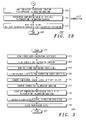
- FIG. 3 in a representative form, shows a flow chart illustrating general methods of compensating an output of a photo sensor to provide a calibrated light reading in accordance with one or more embodiments
- FIG. 4 in a representative form, shows a flow chart illustrating more particular methods of compensating a photo sensor to provide a calibrated light reading in accordance with one or more embodiments.
- the present disclosure concerns accurate light level sensing using, e.g., a photo sensor, and more specifically techniques and apparatus for compensating such photo sensors and associated photo cells for device and assembly variations as well as environmental variations in order to provide accurate light level readings.
- the photo sensors are typically arranged and constructed for facilitating control of other systems, e.g., lighting systems and the like, where ambient light levels or actual light levels, e.g., from an associated lamp or the like, may be used pursuant to control of the associated system. More particularly various inventive concepts and principles embodied in methods and apparatus, for determining or utilizing compensation parameters or coefficients to provide a compensated signal indicative of an actual or absolute light level will be discussed and disclosed.
- the systems of particular interest may vary widely but include outdoor and indoor lighting systems or any other system where ambient or generated light levels and accurate indications thereof can be advantageously used to enhance and improve control of these systems.
- equipment and devices that employ photo sensors and associated photo cells e.g., street lighting or other lighting systems
- light level sensing apparatus and methods can be particularly advantageously utilized, provided they are practiced in accordance with the inventive concepts and principles as taught herein to provide accurate light level indications that have been compensated for device and environmental variations.
- FIG. 1 a simplified and representative high level block diagram of a photo sensor with compensation in accordance with one or more embodiments will be briefly discussed and described.
- a photo sensor that includes various circuitry to facilitate compensation of a photo cell 101 is shown.
- This photo sensor can be packaged in an environmentally resistant package and installed together with a controlled element.
- the photo sensor can be installed together with other circuitry, lamps, etc. in a luminaire as a street light or stadium light, parking lot light, or other lighting fixture.
- the photo sensor with compensation comprises the photo cell 101 that is arranged, constructed, or configured for providing a first signal at 103 , 105 that is indicative of a light level that is input to or incident on the photo cell.
- Various photo cells fashioned from various technologies and available via various providers could be used.
- a Silicon based photo transistor from Osram designated SFH-3410, has been characterized and used with satisfactory results.
- the photo cell 101 is coupled to a supply voltage, shown here as a 5 volt supply, and includes an output terminal 107 where a current proportional to the incident or input light level is provided.
- the indicated light level available from a photo cell or photo sensor can vary from an absolute light level as the result of variations in the particular photo cell, or photo sensor (e.g., packaging including amount of and translucency of any weather resistant coatings, temperature, dust accumulation, etc.).
- compensation adjustment of the indicated light level may be required to provide the necessary accuracy.
- the current at 107 is coupled to a resistive network 109 , where this network is selectively configured, e.g., different resistor values are chosen via a multiplexer 111 , to adjust or control a voltage range of the first signal.
- a variable gain circuit could alternatively be utilized in place of the resistive network. Controlling the voltage range includes setting a lower voltage level and thus higher voltage level for a given range of input light levels for a corresponding photo sensor, which facilitates using an analog to digital converter (ADC) to convert the first signal to a digital first signal.
- ADC analog to digital converter
- the first signal at 103 (voltage) is coupled to a peak detector 113 comprising a series diode and parallel resistor capacitor all as shown.
- a low threshold diode e.g. a Schottky diode with a turn on voltage around 0.3 volts
- a resistor with a relatively high value e.g., in one embodiment near 1 Mega ohm
- relatively physically small and long useful life capacitor e.g., 10 micro farad ceramic capacitor
- an environmental sensor that is configured to provide a second signal indicative of an environmental parameter.
- the environmental sensor in various embodiments comprises a temperature sensor, e.g., LM20 available from National Semiconductors, configured to provide the second signal indicative of an ambient temperature.
- Temperature is one environmental variable that can change dramatically in, e.g., street lighting applications.
- street lights can include a day night sensor that is typically deployed outside of a luminaire and thus will be exposed to the extremes of hot and cold over many seasons and in various geographical locations from near polar conditions to equatorial conditions.
- Lighting fixtures or luminaires can also include a lamp sensor that is typically disposed internal to the luminaire where ambient temperature vary from near the external ambient temperature and rise dramatically as the associated lamp is operational.
- Other environmental sensors that can be employed include a dust accumulation sensor, humidity sensor, or the like, that can change an indicated light level signal or that can be used together with a light level signal pursuant to control of an associated system.
- the temperature sensor 115 provides an output voltage with a known relationship to an ambient temperature surrounding the sensor. This relationship is typically available from the manufacturers' data sheet.
- a processor 117 that is coupled and responsive to the first signal 103 and the second signal, e.g., temperature 116 and configured to provide a compensated signal or compensated light level signal at 119 that is indicative of a calibrated or an absolute light level.
- the compensated light level signal or value, shown at 119 can be provided to a network interface 120 (radio, wired, power line, phone line, etc. based network) and thus other entities or provided to other functions or processes operating within or being performed by the processor 117 .
- the processor includes a memory 121 that can be integral or external to the processor 117 .
- the memory 121 is used to store software routines and various data as well as general operating system that when executed and utilized by the processor 117 result in the processor performing the various functions as further explained herein. It will be appreciated that the processor can perform additional functions other than those that will be further described below.
- the memory is shown with a calibration and compensation coefficients 123 , unit identifier information 125 , experimental and testing control and calibration routines 127 as well as operational control and calculation routines 129 . Each of these will be described below.
- the processor 117 in some embodiments is further configured to provide the compensated signal dependent on an environmental parameter, e.g., dependent on ambient temperature as indicated by the temperature sensor 115 and the light level as indicated by the photo cell 101 .
- an environmental parameter e.g., dependent on ambient temperature as indicated by the temperature sensor 115 and the light level as indicated by the photo cell 101 .
- This and other operations of or processes executed by the processor are controlled by the operational control and calculation routines 129 .
- One of ordinary skill given a particular processor and the discussions herein can readily develop such routines without undue experimentation and thus the particular software routines will not be further discussed.
- the photo sensor of FIG. 1 specifically processor 117 includes or has access to a look up table (LUT) 131 and the processor is further configured to access the LUT to facilitate providing the compensated signal.
- LUT look up table
- the LUT for example, can be a part of memory 121 or integral with the processor 117 or can be remotely located and accessed via the network interface 120 .
- the processor accesses the look up table in accordance with an index (pointer, address, etc) that depends on the first signal or the second signal and when the LUT is remotely situated, the processor may use the Unit ID 125 to access the appropriate LUT.
- the processor can read the first signal, e.g., a light level, as well as the second signal, e.g., a temperature indication, access the LUT for the particular photo sensor at an address or via a pointer that depends on the temperature indication and light level, and retrieve from the LUT a value indicative of the real or absolute light level given the particular photo sensor, the light level as read or indicated and the temperature indication.
- the first signal e.g., a light level
- the second signal e.g., a temperature indication
- the photo sensor specifically the processor 117 is further configured to calculate the compensated signal based at least on one or more of the first signal 103 and the second signal 116 .
- the processor in various embodiments adjusts the first signal (e.g., indicated light level) to account for a sensitivity of the photo cell relative to the light level.
- the processor as part of an initial factory phasing or calibrations procedure or provisioning procedure prior to deployment can be tested or evaluated as facilitated by the experimental control and calibration routines 127 to assess the sensitivity of the photo sensor given the particular photo cell and other assembly variables. This testing, calibrating, or provisioning process can be enabled or entered by providing a corresponding signal at 133 to the processor.
- the input at 133 is also representative of a programming input that allows various data and software routines to be loaded into the photo sensor, specifically processor as needed.
- an indicated light level can be related to the known light level.
- the processor adjusts the first signal in accordance with a light calibration coefficient and a calibration constant associated respectively with the slope and intercept of a line relating the first signal and the light level when the second signal is constant.
- the calibration coefficients and constants can be stored in the memory in the calibration/compensations coefficients area 123 or can be stored at a remote site and retrieved by the processor using the network interface 120 and unit identification information 125 .
- the photo sensor specifically the processor is configured to and adjusts the first signal 103 to account for a sensitivity of the photo cell 101 relative to temperature, where the temperature is indicated by the second signal.
- the processor adjusts the first signal in accordance with one or more temperature coefficients associated with a function relating the first signal to the temperature when the light level is constant to provide a temperature compensated signal.
- the processor then adjusts the temperature compensated signal in accordance with a light calibration coefficient (see above) to provide the compensated signal that indicates or is indicative of the absolute light level.
- a light calibration coefficient see above
- the photo sensor of FIG. 1 operates on digital data points and appropriate processors, e.g., ATMEGA128L available from Atmel Corporation of San Jose, Calif., include analog to digital converters (ADCs) to facilitate this operation.
- ADCs analog to digital converters
- the photo sensor further comprises one or more ADCs configured to convert the first signal and the second signal to, respectively, a first digital value and a second digital value. This is facilitated by providing the processor a reference from a voltage reference 135 .
- the range of the first digital values is controlled using the resistive circuit or network 109 coupled to the photo cell as selectively configured via the multiplexer 111 which is controlled from the processor 117 to set a range for the first signal.
- This range is set to be approximately 3.3 volts (i.e., the reference voltage) over expected light levels.
- the processor 117 can also include a day night sensor input (DN SENSOR IN 137 ) and a day night temperature input (DN TEMP IN 139 ). These are inputs from a day night sensor where this sensor is similar to the photo cell 101 and peak detector 113 and the temperature input is provided by a temperature sensor that is similar to the temperature sensor 115 . As noted above, the day night sensor is likely situated differently (external to luminaire with external ambient temperatures) than the photo or lamp sensor that is detailed in FIG. 1 . However the principles and concepts discussed and described herein for calibration or compensation of the photo or lamp sensor will apply to the day night sensor.
- FIG. 2 shows the flow chart 200 which starts at 201 and comprises a series of processes 203 that determine one or more light calibration coefficients followed by a series of processes 205 that determine one or more temperature coefficients.
- a final series of processes 207 illustrate utilization of these coefficients to compensate or adjust a given light level indication such that the compensated light level is representative of a real or absolute light level with the flow chart then ending 209 .
- 2A can be repeated as warranted and generally will be executed at least in part for each photo sensor as a part of manufacturing or deploying the photo sensor used as a lamp sensor or as a day night sensor.
- the methods can be practiced using the photo sensor of FIG. 1 or similarly configured sensors executing experimental control and calibration routines.
- the flow chart of FIG. 2A illustrates a method of determining parameters for compensation of a photo sensor, where the method includes, after setting up in a generally known manner a calibrated light source and the device, e.g., photo sensor, under test 221 , controlling or maintaining 223 a temperature of the photo sensor to, e.g., 25 degrees C.; varying an input light level to the photo sensor to provide first indications of the light level with each of the first indications corresponding to a respective one of a plurality of light levels.
- the input light level is set 225 to a first level, e.g., 1 foot candle
- the photo sensor output Po is read
- the light level is incremented by, e.g., 1 foot candle 229
- the light level is compared to an upper level Y 231 , e.g., 12 foot candles, and the reading Po 227 and incrementing 229 is repeated until Y is reached 231 .
- determining one or more light calibration coefficients based on the first indications of the light level is performed 233 .
- the determining one or more light calibrations coefficients further comprises determining a light calibration coefficient corresponding to a slope of a line between two or more of the first indications and a light calibration constant corresponding to an intercept of the line.
- the slope m can be defined as the light calibration coefficient and c as the calibration constant. As noted above c is often small enough that it can be assumed to be 0.
- the method in various embodiments further includes after setting or controlling the input light level to a constant value Z 235 , e.g., 5 foot candles, varying the temperature of the photo sensor to provide second indications of the light level with each of the second indications corresponding to a respective one of a plurality of temperatures. More specifically, the temperature is set to T 1 237 , e.g., 0 degrees C., the photo sensor output Po is read 239 , the temperature is incremented 241 by e.g., 5 degrees C., and compared to an upper limit T 2 243 , e.g., 85 degrees C. The reading the sensor output Po 239 and incrementing temperature 241 is repeated until the upper limit is reached as determined at 231 .
- a constant value Z 235 e.g., 5 foot candles
- determining one or more temperature coefficients based on the second indications of the light level is undertaken 245 , 247 .
- normalizing the second indications in accordance with the second indication obtained at a known temperature corresponding to the controlling the temperature is performed and then the determining the one or more temperature coefficients is based on the second indications as normalized.
- the photo sensor output is normalized 245 by dividing each Po by the value of Po at a given temperature, e.g., 25 degrees C. (P25). Then the temperature coefficients are determined at 247 .
- the one or more temperature coefficients as determined define a temperature calibration equation to facilitate temperature compensation of any indication of a light level.
- a polynomial equation has been found to provide a reasonably accurate model.
- the normalized photo sensor outputs are used. Once the data points Po are collected and normalized (designated Pn), the relationship between the normalized data points can be determined with the help of a curve fitting method, e.g., the least-squares method as generally known.
- any light level Po can be temperature compensated.
- the any indication of a light level as temperature compensated is further calibrated to provide a calibrated or real light level.
- this is done in accordance with the one or more light calibration coefficients which were determined as a slope of a line between two or more of the first indications and a light calibration constant corresponding to an intercept of the line.
- the absolute or actual or real light level is found by subtracting the calibration constant from Pc and dividing the result by the calibration coefficient 252 .
- FIG. 3 shows methods that facilitate compensating a photo sensor output from a given photo sensor once the experimental efforts discussed above have been performed and the calibration coefficient and constant as well as temperature compensation coefficients have been determined and stored for the given photo sensor.
- a method of compensating an output of a photo sensor to provide a calibrated light reading comprises obtaining one or more light calibration coefficients (calibration coefficient 303 and calibration constant 305 ) and one or more temperature coefficients 307 all corresponding to the photo sensor. These coefficients can be obtained from experimental or calibration results as discussed above.
- the coefficients can be stored in and read from a memory that is integral with the photo sensor, e.g., part of the associated processor, or in a memory that is remote from the photo sensor and accessed via the network interface 120 .
- the method further includes getting a light output indication for the photo sensor and a temperature indication from a temperature sensor included with the photo sensor 309 . Additionally the method includes calculating the calibrated light reading based on the one or more temperature coefficients and the one or more light calibration coefficients, the temperature indication, and the light output indication. In some embodiments, the calculating the calibrated light reading further comprises calculating a first compensated light output indication based on an equation corresponding to the one or more temperature coefficients. As shown in the flow chart, the calculating the calibrated light reading further comprises converting the temperature indication to a temperature 311 and then computing a temperature calibration equation given the temperature 313 . Given the value from the temperature calibration equation, 325 calculates the first compensated light output or compensated photo sensor output by dividing the light output indication from 309 by the resultant value for the temperature calibration equation 313 .
- calculating the calibrated light reading further comprises calculating the calibrated light reading based on the first compensated light output indication Pc from 315 and the one or more light calibration coefficients.
- the calibrated or actual light level is (Pc ⁇ calibration constant)/(calibration coefficient) 317 .
- the photo sensor output Po can then be adjusted to the calibrated light level 319 and the method of FIG. 3 ends 321 . Note the method can be repeated as needed for additional photo sensor light level outputs and as ambient or sensed temperature changes. This method is appropriate for implementation in the photo sensor of FIG. 1 for providing calibrated or actual light level readings or indications from a lamp sensor or from a day night sensor or other similarly arranged photo sensors and the like.
- FIG. 4 illustrates various methods for use in a photo sensor that uses digital values for the light level indications and temperature indications.
- This method begins at 401 and then shows getting a temperature sensor ADC value, a photo sensor ADC light output value, and the light calibration coefficients and temperature compensation coefficients, i.e., temperature calibration equation 403 .
- the temperature ADC value is converted to a voltage reading 405 . This is accomplished by multiplying the temperature ADC value by a factor indicative of the voltage represented by each digital step. In one embodiment this is 3.3 mV and the total range is 3.3.
- To temperature sensor voltage
- To temperature sensor ADC value (3.3/1023) mV.
- the temperature sensor voltage (To) is then converted to degrees Celsius 407 using a formula corresponding to the temperature sensor that is being used, where the formula is normally available from the manufacturer of the sensor. In one embodiment, the actual temperature in degrees C. is found using the equation shown at 407 .
- the temperature compensated photo sensor ADC value is found at 409 and is given by dividing the photo sensor ADC value by the temperature calibration equation evaluated at the temperature that was found at 407 .
- the light level in foot candles is found at 411 and is given by dividing the compensated photo sensor ADC value by the calibration coefficient (note this assumes the calibration constant is or is near zero and thus can be ignored, otherwise the constant would need to be subtracted with the result divided by the coefficient).
- the real light level is provided at 413 and the method ends at 415 .
- FIG. 1 and other sensor apparatus with similar functionality is suitable for implementing various methods of compensating one or more photo sensors and associated photo cells. It will be appreciated that the methods uses many of the inventive concepts and principles discussed in detail above and thus this description will be somewhat in the nature of a summary with various details generally available in the earlier descriptions. This method can be implemented in one or more of the structures or apparatus described earlier or other similarly configured and arranged structures.
- various embodiments include a method of compensating a photo sensor, where the method includes providing a first signal indicative of a light level and a second signal indicative of an environmental parameter. Then calculating, responsive to the first signal and the second signal, a compensated signal that is indicative of an absolute light level.
- the providing a second signal comprises providing the second signal indicative of an ambient temperature and the calculating the compensated signal is dependent on the ambient temperature as indicated, e.g., by a temperature sensor and the light level as indicated, e.g., by a photo cell.
- the calculating can include accessing a look up table to facilitate providing the compensated signal and the accessing the look up table can be in accordance with an index that depends on one or more of the first signal and the second signal.
- the calculating the compensated signal is normally based at least on one or more of the first signal and the second signal and can comprise adjusting the first signal to account for a sensitivity of a photo cell relative to the light level.
- the adjusting the first signal can comprise adjusting the first signal in accordance with a light calibration coefficient and a calibration constant associated respectively with the slope and intercept of a line relating the first signal and the light level when the second signal is constant.
- the calculating the compensated signal can also comprise adjusting the first signal to account for a sensitivity of a photo cell relative to temperature, where the temperature is indicated by the second signal.
- the adjusting the first signal can comprise adjusting the first signal in accordance with one or more temperature coefficients associated with a function relating the first signal to the temperature when the light level is constant to provide a temperature compensated signal.
- the adjusting the first signal can also comprises adjusting the temperature compensated signal in accordance with a light calibration coefficient to provide the compensated signal that is indicative of the absolute light level.
- the providing the first signal and providing the second signal can include converting the first signal and the second signal to a, respective, first digital value and second digital value.
- a range of the first digital value can be controlled using a resistive circuit that is selectively configured and coupled to a photo sensor to set a range for the first signal.
Abstract
Description
Temperature(Deg.C.)=To−(DC offset at 0° C.)/TemperatureCoefficient(mV/°C)
where To is the voltage reading provided by the sensor. More specifically, for the LM20 sensor:
Actual temperature(deg C.)=(To−1.8663)/(−11.69 mv/Deg C.)
Po=mx+c
Where Po is the output of the photo sensor, x is the input light level in foot candles to the photo sensor In order to determine the value of m and c, two-points can be chosen (x1, Po1, and x2, Po2) and the values can be determined as
and c is the value of Po when x=0. Thus the determining one or more light calibrations coefficients further comprises determining a light calibration coefficient corresponding to a slope of a line between two or more of the first indications and a light calibration constant corresponding to an intercept of the line. The slope m can be defined as the light calibration coefficient and c as the calibration constant. As noted above c is often small enough that it can be assumed to be 0.
Pn=dt 2 +et+f
where Pn is the Normalized photo sensor output, t is temperature, and d, e and f are the coefficients of the least-squares approximation for fitting the normalized data points to the quadratic equation. It will be appreciated that as little as 3 data points or couples (Po and t) are required to find d, e, and f where d, e, and f are the temperature coefficients that can be used to compensate a light level indication for a particular temperature. Note that f=normalized light level when t=0.
Claims (30)
Priority Applications (3)
| Application Number | Priority Date | Filing Date | Title |
|---|---|---|---|
| US11/476,498 US7608815B2 (en) | 2005-06-30 | 2006-06-28 | Photo detector with compensated output and method involving same |
| CA002612801A CA2612801A1 (en) | 2005-06-30 | 2006-06-30 | Compensation for photo sensor |
| PCT/CA2006/001075 WO2007003042A1 (en) | 2005-06-30 | 2006-06-30 | Compensation for photo sensor |
Applications Claiming Priority (3)
| Application Number | Priority Date | Filing Date | Title |
|---|---|---|---|
| US69562705P | 2005-06-30 | 2005-06-30 | |
| US69525205P | 2005-06-30 | 2005-06-30 | |
| US11/476,498 US7608815B2 (en) | 2005-06-30 | 2006-06-28 | Photo detector with compensated output and method involving same |
Publications (2)
| Publication Number | Publication Date |
|---|---|
| US20070001833A1 US20070001833A1 (en) | 2007-01-04 |
| US7608815B2 true US7608815B2 (en) | 2009-10-27 |
Family
ID=37588763
Family Applications (1)
| Application Number | Title | Priority Date | Filing Date |
|---|---|---|---|
| US11/476,498 Expired - Fee Related US7608815B2 (en) | 2005-06-30 | 2006-06-28 | Photo detector with compensated output and method involving same |
Country Status (3)
| Country | Link |
|---|---|
| US (1) | US7608815B2 (en) |
| CA (1) | CA2612801A1 (en) |
| WO (1) | WO2007003042A1 (en) |
Cited By (8)
| Publication number | Priority date | Publication date | Assignee | Title |
|---|---|---|---|---|
| US20100124059A1 (en) * | 2008-11-19 | 2010-05-20 | Gerard Duffy | Outdoor Low Power LED Lamp |
| US8502456B2 (en) | 2010-09-09 | 2013-08-06 | Ipixc Llc | Managing light system energy use |
| US9332616B1 (en) | 2014-12-30 | 2016-05-03 | Google Inc. | Path light feedback compensation |
| US9569943B2 (en) | 2014-12-30 | 2017-02-14 | Google Inc. | Alarm arming with open entry point |
| US9747769B2 (en) | 2014-12-30 | 2017-08-29 | Google Inc. | Entry point opening sensor |
| US10339773B2 (en) | 2014-12-30 | 2019-07-02 | Google Llc | Home security system with automatic context-sensitive transition to different modes |
| US10529221B2 (en) | 2016-04-19 | 2020-01-07 | Navio International, Inc. | Modular approach for smart and customizable security solutions and other applications for a smart city |
| US10536673B2 (en) * | 2015-03-31 | 2020-01-14 | Westire Technology Limited | Smart city closed camera photocell and street lamp device |
Families Citing this family (6)
| Publication number | Priority date | Publication date | Assignee | Title |
|---|---|---|---|---|
| US8433426B2 (en) | 2005-06-30 | 2013-04-30 | Led Roadway Lighting Ltd | Adaptive energy performance monitoring and control system |
| EP1899695B8 (en) * | 2005-06-30 | 2012-06-27 | LED Roadway Lighting Ltd. | Method and system for luminance characterization |
| US8290710B2 (en) * | 2007-09-07 | 2012-10-16 | Led Roadway Lighting Ltd. | Streetlight monitoring and control |
| GB0916883D0 (en) * | 2009-09-25 | 2009-11-11 | St Microelectronics Ltd | Ambient light detection |
| US20110273303A1 (en) * | 2010-05-05 | 2011-11-10 | Ils Technology Llc | System and Method to Collect Status Information From Light Based Indicator Systems Such as Stack Lights, Status Lights, Traffic Lights, Safety Lights |
| US11740695B2 (en) * | 2020-08-11 | 2023-08-29 | Inseye Inc. | Eye tracking system for use in head-mounted display units |
Citations (21)
| Publication number | Priority date | Publication date | Assignee | Title |
|---|---|---|---|---|
| US3705316A (en) | 1971-12-27 | 1972-12-05 | Nasa | Temperature compensated light source using a light emitting diode |
| US4694157A (en) | 1984-10-18 | 1987-09-15 | Matsushita Electric Works, Ltd. | Temperature compensated electro-optical light transmission circuit for use in a position detector |
| US4758767A (en) | 1987-05-15 | 1988-07-19 | Multipoint Control Systems, Incorporated | Self-contained analog photodiode light sensing head |
| US5055669A (en) | 1989-06-29 | 1991-10-08 | Multipoint Control Systems | Constant-current light-sensing system |
| US5266792A (en) | 1991-10-28 | 1993-11-30 | Simmonds Precision Products, Inc. | Temperature compensated optical detector |
| US5382785A (en) * | 1992-05-04 | 1995-01-17 | Diolase Corporation | Laser beam delivery path and target proximity sensor |
| US5446277A (en) | 1993-12-27 | 1995-08-29 | Rutter; Robert E. | Automated lamp monitoring system for comparing light intensities with a preselected valve |
| JPH09304494A (en) | 1996-05-10 | 1997-11-28 | Toyo Commun Equip Co Ltd | Sensor unit for sensing magnetic field or electric field utilizing magneto-optic effect, and method for compensating temperature characteristic thereof, and temperature sensor unit |
| US5715045A (en) * | 1996-05-15 | 1998-02-03 | Laser Technology, Inc. | Countermeasure detecting circuit, and associated method, for a laser speed detecting apparatus |
| US5796291A (en) | 1994-04-15 | 1998-08-18 | Ssi Technologies, Inc. | Method and apparatus for compensating for temperature fluctuations in the input to a gain circuit |
| US5883830A (en) | 1995-12-29 | 1999-03-16 | Intel Corporation | CMOS imaging device with integrated flash memory image correction circuitry |
| US5929982A (en) * | 1997-02-04 | 1999-07-27 | Tektronix, Inc. | Active APD gain control for an optical receiver |
| US5990628A (en) * | 1994-12-23 | 1999-11-23 | H.P.M. Industries Pty Limited | Light level sensor for detecting the level of incident light and discriminating between natural and artificial light |
| US6191408B1 (en) * | 1998-04-15 | 2001-02-20 | Honda Giken Koygo Kabushiki Kaisha | Photosensor signal processing apparatus |
| US20010023944A1 (en) * | 2000-03-23 | 2001-09-27 | Hioki Denki Kabushiki Kaisha | Photodetector |
| US6693394B1 (en) | 2002-01-25 | 2004-02-17 | Yazaki North America, Inc. | Brightness compensation for LED lighting based on ambient temperature |
| US20040067060A1 (en) * | 2002-10-08 | 2004-04-08 | Aronson Lewis B. | Optical transceiver module with multipurpose internal serial bus |
| US20040069929A1 (en) * | 2000-12-01 | 2004-04-15 | Honda Giken Kogyo Kabushiki Kaisha | Output-compensating device for image sensor |
| US6852966B1 (en) | 2002-09-27 | 2005-02-08 | Finisar Corporation | Method and apparatus for compensating a photo-detector |
| US7060970B2 (en) * | 2003-01-02 | 2006-06-13 | Samsung Electronics Co., Ltd. | Temperature compensating device for APD optical receiver |
| US7098443B2 (en) * | 2004-07-30 | 2006-08-29 | Avago Technologies Ecbu Ip (Singapore) Pte. Ltd. | Temperature compensation method and apparatus for color sensors |
-
2006
- 2006-06-28 US US11/476,498 patent/US7608815B2/en not_active Expired - Fee Related
- 2006-06-30 CA CA002612801A patent/CA2612801A1/en not_active Abandoned
- 2006-06-30 WO PCT/CA2006/001075 patent/WO2007003042A1/en active Application Filing
Patent Citations (22)
| Publication number | Priority date | Publication date | Assignee | Title |
|---|---|---|---|---|
| US3705316A (en) | 1971-12-27 | 1972-12-05 | Nasa | Temperature compensated light source using a light emitting diode |
| US4694157A (en) | 1984-10-18 | 1987-09-15 | Matsushita Electric Works, Ltd. | Temperature compensated electro-optical light transmission circuit for use in a position detector |
| US4758767A (en) | 1987-05-15 | 1988-07-19 | Multipoint Control Systems, Incorporated | Self-contained analog photodiode light sensing head |
| US5055669A (en) | 1989-06-29 | 1991-10-08 | Multipoint Control Systems | Constant-current light-sensing system |
| US5266792A (en) | 1991-10-28 | 1993-11-30 | Simmonds Precision Products, Inc. | Temperature compensated optical detector |
| US5382785A (en) * | 1992-05-04 | 1995-01-17 | Diolase Corporation | Laser beam delivery path and target proximity sensor |
| US5446277A (en) | 1993-12-27 | 1995-08-29 | Rutter; Robert E. | Automated lamp monitoring system for comparing light intensities with a preselected valve |
| US5796291A (en) | 1994-04-15 | 1998-08-18 | Ssi Technologies, Inc. | Method and apparatus for compensating for temperature fluctuations in the input to a gain circuit |
| US5990628A (en) * | 1994-12-23 | 1999-11-23 | H.P.M. Industries Pty Limited | Light level sensor for detecting the level of incident light and discriminating between natural and artificial light |
| US5883830A (en) | 1995-12-29 | 1999-03-16 | Intel Corporation | CMOS imaging device with integrated flash memory image correction circuitry |
| JPH09304494A (en) | 1996-05-10 | 1997-11-28 | Toyo Commun Equip Co Ltd | Sensor unit for sensing magnetic field or electric field utilizing magneto-optic effect, and method for compensating temperature characteristic thereof, and temperature sensor unit |
| US5715045A (en) * | 1996-05-15 | 1998-02-03 | Laser Technology, Inc. | Countermeasure detecting circuit, and associated method, for a laser speed detecting apparatus |
| US5929982A (en) * | 1997-02-04 | 1999-07-27 | Tektronix, Inc. | Active APD gain control for an optical receiver |
| US6191408B1 (en) * | 1998-04-15 | 2001-02-20 | Honda Giken Koygo Kabushiki Kaisha | Photosensor signal processing apparatus |
| US20010023944A1 (en) * | 2000-03-23 | 2001-09-27 | Hioki Denki Kabushiki Kaisha | Photodetector |
| US20040069929A1 (en) * | 2000-12-01 | 2004-04-15 | Honda Giken Kogyo Kabushiki Kaisha | Output-compensating device for image sensor |
| US7256378B2 (en) * | 2000-12-01 | 2007-08-14 | Honda Giken Kogyo Kabushiki Kaisha | Output-compensating device for image sensor |
| US6693394B1 (en) | 2002-01-25 | 2004-02-17 | Yazaki North America, Inc. | Brightness compensation for LED lighting based on ambient temperature |
| US6852966B1 (en) | 2002-09-27 | 2005-02-08 | Finisar Corporation | Method and apparatus for compensating a photo-detector |
| US20040067060A1 (en) * | 2002-10-08 | 2004-04-08 | Aronson Lewis B. | Optical transceiver module with multipurpose internal serial bus |
| US7060970B2 (en) * | 2003-01-02 | 2006-06-13 | Samsung Electronics Co., Ltd. | Temperature compensating device for APD optical receiver |
| US7098443B2 (en) * | 2004-07-30 | 2006-08-29 | Avago Technologies Ecbu Ip (Singapore) Pte. Ltd. | Temperature compensation method and apparatus for color sensors |
Non-Patent Citations (1)
| Title |
|---|
| English abstract(AD), Nov. 28, 1997, Yonezawa et al. |
Cited By (19)
| Publication number | Priority date | Publication date | Assignee | Title |
|---|---|---|---|---|
| US20100124059A1 (en) * | 2008-11-19 | 2010-05-20 | Gerard Duffy | Outdoor Low Power LED Lamp |
| WO2010059851A2 (en) * | 2008-11-19 | 2010-05-27 | Gerard Duffy | Outdoor low power led lamp |
| WO2010059851A3 (en) * | 2008-11-19 | 2012-05-03 | Gerard Duffy | Outdoor low power led lamp |
| US8277080B2 (en) * | 2008-11-19 | 2012-10-02 | Gerard Duffy | Outdoor low power LED lamp |
| US8502456B2 (en) | 2010-09-09 | 2013-08-06 | Ipixc Llc | Managing light system energy use |
| US8716942B2 (en) | 2010-09-09 | 2014-05-06 | Ipixc Llc | Managing light system energy use |
| US8963433B2 (en) | 2010-09-09 | 2015-02-24 | Ipixc Llc | Managing light system energy use |
| US9569943B2 (en) | 2014-12-30 | 2017-02-14 | Google Inc. | Alarm arming with open entry point |
| US9332616B1 (en) | 2014-12-30 | 2016-05-03 | Google Inc. | Path light feedback compensation |
| US9668320B2 (en) | 2014-12-30 | 2017-05-30 | Google Inc. | Path light feedback compensation |
| US9747769B2 (en) | 2014-12-30 | 2017-08-29 | Google Inc. | Entry point opening sensor |
| US9940798B2 (en) | 2014-12-30 | 2018-04-10 | Google Llc | Alarm arming with open entry point |
| US10127785B2 (en) | 2014-12-30 | 2018-11-13 | Google Llc | Entry point opening sensor |
| US10290191B2 (en) * | 2014-12-30 | 2019-05-14 | Google Llc | Alarm arming with open entry point |
| US10339773B2 (en) | 2014-12-30 | 2019-07-02 | Google Llc | Home security system with automatic context-sensitive transition to different modes |
| US10536673B2 (en) * | 2015-03-31 | 2020-01-14 | Westire Technology Limited | Smart city closed camera photocell and street lamp device |
| US10529221B2 (en) | 2016-04-19 | 2020-01-07 | Navio International, Inc. | Modular approach for smart and customizable security solutions and other applications for a smart city |
| US10950118B2 (en) | 2016-04-19 | 2021-03-16 | Navio International, Inc. | Modular sensing systems and methods |
| US11790760B2 (en) | 2016-04-19 | 2023-10-17 | Navio International, Inc. | Modular sensing systems and methods |
Also Published As
| Publication number | Publication date |
|---|---|
| US20070001833A1 (en) | 2007-01-04 |
| CA2612801A1 (en) | 2007-01-11 |
| WO2007003042B1 (en) | 2007-03-08 |
| WO2007003042A1 (en) | 2007-01-11 |
Similar Documents
| Publication | Publication Date | Title |
|---|---|---|
| US7608815B2 (en) | Photo detector with compensated output and method involving same | |
| KR101369435B1 (en) | Apparatus for evaluating characteristics of solar cell | |
| US6974973B2 (en) | Apparatus for determining temperature of an active pixel imager and correcting temperature induced variations in an imager | |
| US7674035B2 (en) | Digital temperature sensors and calibration thereof | |
| CN101078656B (en) | Thermometer calibration | |
| US6736540B1 (en) | Method for synchronized delta-VBE measurement for calculating die temperature | |
| CN101435721B (en) | Infrared target temperature correction system and method | |
| CN100397055C (en) | Calibrating temperature sensors of weathering devices by means of contactless temperature measurement | |
| Midtgard et al. | A qualitative examination of performance and energy yield of photovoltaic modules in southern Norway | |
| Carrillo et al. | Uncertainties on the outdoor characterization of PV modules and the calibration of reference modules | |
| TW200630599A (en) | Programmable ideality factor compensation in temperature sensors | |
| CN110940432B (en) | Temperature sensing circuit | |
| EP1724560A1 (en) | Infrared temperature sensing device | |
| KR100817806B1 (en) | Sensor temperature control in a thermal anemometer | |
| US7813885B2 (en) | Method and apparatus for measurement of AC voltages in an HVAC system | |
| USH562H (en) | Accurate electronic thermometer | |
| Skinner et al. | Using smart sensor strings for continuous monitoring of temperature stratification in large water bodies | |
| Osterwald et al. | On the reliability of photovoltaic short-circuit current temperature coefficient measurements | |
| CN112461363A (en) | Offset nulling for optical power meters | |
| US20190376924A1 (en) | Sensor device | |
| Bharadwaj et al. | Design, fabrication and evaluation of solar irradiation meter | |
| Cutkosky et al. | Standard cell enclosure with 20-μK stability | |
| US9915568B2 (en) | Circuit device, temperature detection device, electronic device, and temperature detection method | |
| Verbelen et al. | Automated test chamber for indoor photovoltaics | |
| JP2006105870A (en) | Temperature sensor and method of compensating temperature sensor |
Legal Events
| Date | Code | Title | Description |
|---|---|---|---|
| AS | Assignment |
Owner name: STREETLIGHT INTELLIGENCE, INC., CANADA Free format text: ASSIGNMENT OF ASSIGNORS INTEREST;ASSIGNORS:SHARMA, PRATIBHA;KURZ, GERALD A.;CHO, YOUNG JEONG;AND OTHERS;REEL/FRAME:018056/0352 Effective date: 20060627 |
|
| FEPP | Fee payment procedure |
Free format text: PAYER NUMBER DE-ASSIGNED (ORIGINAL EVENT CODE: RMPN); ENTITY STATUS OF PATENT OWNER: SMALL ENTITY Free format text: PAYOR NUMBER ASSIGNED (ORIGINAL EVENT CODE: ASPN); ENTITY STATUS OF PATENT OWNER: SMALL ENTITY |
|
| FEPP | Fee payment procedure |
Free format text: PAYOR NUMBER ASSIGNED (ORIGINAL EVENT CODE: ASPN); ENTITY STATUS OF PATENT OWNER: SMALL ENTITY |
|
| AS | Assignment |
Owner name: LED ROADWAY LIGHTING LTD, CANADA Free format text: ASSIGNMENT OF ASSIGNORS INTEREST;ASSIGNOR:STREETLIGHT INTELLIGENCE INC AND STREETLIGHT INTELLIGENCE INTERNATIONAL LTD;REEL/FRAME:027276/0240 Effective date: 20111118 |
|
| FPAY | Fee payment |
Year of fee payment: 4 |
|
| REMI | Maintenance fee reminder mailed | ||
| LAPS | Lapse for failure to pay maintenance fees |
Free format text: PATENT EXPIRED FOR FAILURE TO PAY MAINTENANCE FEES (ORIGINAL EVENT CODE: EXP.) |
|
| STCH | Information on status: patent discontinuation |
Free format text: PATENT EXPIRED DUE TO NONPAYMENT OF MAINTENANCE FEES UNDER 37 CFR 1.362 |
|
| FP | Lapsed due to failure to pay maintenance fee |
Effective date: 20171027 |