US7618182B1 - Dust-free low pressure mixing system with jet ring adapter - Google Patents
Dust-free low pressure mixing system with jet ring adapter Download PDFInfo
- Publication number
- US7618182B1 US7618182B1 US12/176,540 US17654008A US7618182B1 US 7618182 B1 US7618182 B1 US 7618182B1 US 17654008 A US17654008 A US 17654008A US 7618182 B1 US7618182 B1 US 7618182B1
- Authority
- US
- United States
- Prior art keywords
- eductor
- dust
- dry component
- mixing system
- inlet
- Prior art date
- Legal status (The legal status is an assumption and is not a legal conclusion. Google has not performed a legal analysis and makes no representation as to the accuracy of the status listed.)
- Expired - Fee Related
Links
Images


Classifications
-
- B—PERFORMING OPERATIONS; TRANSPORTING
- B01—PHYSICAL OR CHEMICAL PROCESSES OR APPARATUS IN GENERAL
- B01F—MIXING, e.g. DISSOLVING, EMULSIFYING OR DISPERSING
- B01F23/00—Mixing according to the phases to be mixed, e.g. dispersing or emulsifying
- B01F23/50—Mixing liquids with solids
- B01F23/54—Mixing liquids with solids wetting solids
-
- B—PERFORMING OPERATIONS; TRANSPORTING
- B01—PHYSICAL OR CHEMICAL PROCESSES OR APPARATUS IN GENERAL
- B01F—MIXING, e.g. DISSOLVING, EMULSIFYING OR DISPERSING
- B01F25/00—Flow mixers; Mixers for falling materials, e.g. solid particles
- B01F25/10—Mixing by creating a vortex flow, e.g. by tangential introduction of flow components
-
- B—PERFORMING OPERATIONS; TRANSPORTING
- B01—PHYSICAL OR CHEMICAL PROCESSES OR APPARATUS IN GENERAL
- B01F—MIXING, e.g. DISSOLVING, EMULSIFYING OR DISPERSING
- B01F25/00—Flow mixers; Mixers for falling materials, e.g. solid particles
- B01F25/30—Injector mixers
- B01F25/31—Injector mixers in conduits or tubes through which the main component flows
- B01F25/312—Injector mixers in conduits or tubes through which the main component flows with Venturi elements; Details thereof
- B01F25/3124—Injector mixers in conduits or tubes through which the main component flows with Venturi elements; Details thereof characterised by the place of introduction of the main flow
- B01F25/31242—Injector mixers in conduits or tubes through which the main component flows with Venturi elements; Details thereof characterised by the place of introduction of the main flow the main flow being injected in the central area of the venturi, creating an aspiration in the circumferential part of the conduit
-
- B—PERFORMING OPERATIONS; TRANSPORTING
- B01—PHYSICAL OR CHEMICAL PROCESSES OR APPARATUS IN GENERAL
- B01F—MIXING, e.g. DISSOLVING, EMULSIFYING OR DISPERSING
- B01F35/00—Accessories for mixers; Auxiliary operations or auxiliary devices; Parts or details of general application
- B01F35/181—Preventing generation of dust or dirt; Sieves; Filters
- B01F35/184—Preventing generation of dust
Definitions
- the present embodiments relate to a closed, high-velocity mixing system for use with mixing drilling fluids.
- the mixing of liquids with particulates requires a mixing system that provides a dust-free mixing system.
- the flow of the liquid during mixing should be turbulent to ensure that the particulates are sufficiently agitated to create a complete mixture of the particulates and the liquid.
- FIGS. 1 a and 1 b depict an embodiment of the eductor that is adapted for use with the dust-free mixing system.
- FIG. 2 depicts a schematic of the dust-free mixing system.
- FIG. 3 depicts a plan view and elevated view of an embodiment of the flow promoter adapted for use with the dust-free mixing system.
- FIG. 4 depicts a top view of a flow promoter.
- FIG. 5 depicts an embodiment of the fluidizer adapted for use with the dust-free mixing system.
- FIG. 6 depicts a top view of an embodiment of the cyclone separator adapted for use with the dust-free mixing system.
- FIG. 7 depicts a side view of an embodiment of the cyclone separator adapted for use with the dust-free mixing system
- FIG. 8 depicts a top view of an embodiment of the radial pre-mixer usable with the dust-free mixing system.
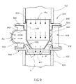
- FIG. 9 depicts a section of the radial pre-mixer taken generally along line 3 - 3 of FIG. 2 .
- FIG. 10 depicts an enlarged sectional view of the radial pre-mixer.
- FIG. 11 is a perspective of the radial pre-mixer with certain parts broken away.
- FIG. 12 is an exploded view of the radial pre-mixer depicted in FIG. 11 .
- FIG. 13 is a schematic view of a jet-ring adapter.
- the present embodiments relate generally to a dust-free mixing system for use with drilling fluids.
- the dust-free mixing system can have an eductor.
- the eductor can have a housing with an axial bore for receiving a first suction induction port.
- the first suction induction port is for receiving a first dry component.
- the axial bore can receive a second dry component through a second suction induction port.
- the axial bore can also have a third induction port for receiving a third dry component.
- the first dry component, second dry component, and third component can be mixed in a high-velocity low pressure mixing region with a pressurized liquid flowing through the axial bore, creating an eductor discharge, which is a uniformly mixed slurry.
- the eductor discharge is generally also referred to as a drilling fluid or a drilling mud, however, the eductor discharge does not have to be mud.
- first suction induction port, second suction induction port, and third suction induction port can have a vacuum pressure creating a near perfect vacuum when the pressurized liquid is traveling at least 72 feet per second.
- a vacuum gauge can be in communication with the axial bore for indicating the vacuum within.
- the eductor has a nozzle with a non-circular axisymmetrical lobe shaped orifice disposed within the axial bore.
- the pressurized fluid can enter the axial bore and flow through the nozzle. As the pressurized liquid exits the non-circular axisymmetrical lobe shaped orifice the pressurized liquid will have an axial flow path and a radial flow path.
- the low pressure-mixing region can be in communication with the nozzle.
- a parabolic inlet On a side of the low-pressure mixing region opposite the nozzle can be a parabolic inlet, which can be in communication with the low pressure-mixing region.
- the parabolic inlet can be integrally connected to a cylindrical throat.
- the cylindrical throat can be integrally connected with a conical diffuser. As the eductor discharge traverses from the cylindrical throat to the conical diffuser a Venturi effect can be formed.
- the eductor discharge leaves the conical diffuser with a pressure recovery of at least 50 percent of the initial pressure of the pressurized liquid.
- the pressure recovery can range from about 50 percent to about 80 percent of the original pressure of the pressurized liquid.
- the embodiments of the eductor generally relate to a closed mixing system for mixing at least two separate components or constituents.
- An eductor mixing system is effective in continuously mixing separate components such as liquids and particulate materials to form uniformed mixed slurry.
- uniform mixed slurry is interpreted herein as including granular materials, powdered materials, and other pressure soluble materials.
- the eductor system thoroughly mixes the liquid with the particulate material and obtains a relatively high negative pressure or vacuum level, which is efficiently generated to positively draw or suck the particulate material into the eductor system.
- the working pressurized liquid is directed through a nozzle to produce a high-velocity.
- the high-velocity liquid stream generates a low-pressure region adjacent the down stream end of the particulate material.
- the low-pressure zone causes the particulate material to be drawn or sucked through a suction port into a mixing region created by the swirling liquid stream adjacent the nozzle for the particulate material.
- the eductor connects to the radial pre-mixer, which has swirl.
- Swirl is the circumferential velocity component that will cause a fluid stream to rotate about its axis. Swirl changes energy momentum into centrifugal force that will cause a rotating stream to have at least two velocity components: a) axial, and b) radial.
- the heavier or denser material (solids) or liquid to the outside while the radial velocity will move the lighter constituents to the inside toward the longitudinal axis.
- the introduction of swirl enhances mixing due in part to an increase in turbulence.
- Swirl imparts radial acceleration to particles, modifying their motion and dispersion behavior, and enhances interfacial contact between two or more constituents due to stretching, straining and folding of particles and droplets to form a uniform mixture.
- the total energy in a steadily flowing fluid is constant along its flow path and as the velocity of the fluid increases the pressure within the fluid decreases.
- the intense swirling motion of the pressurized liquid when it enters the mixing region provides a sheet of liquid that has a uniform pressure profile.
- the eductor provides a passive method of energizing the fluid boundary layer in a conically shaped diffuser, providing a method to reduce viscous drag with a diffuser having a short throat, and providing a method that generates a vacuum with a nozzle fluid velocity of about 60 feet per second and an operating pressure drop of about 25 psig.
- the dust-free low pressure mixing system can have a bulk storage tank in communication with the second suction induction port.
- the bulk storage tank has a body and the body has an inlet port.
- the bulk storage tank also has a discharge segment connected to the body.
- the discharge segment can be conical or dish shaped.
- the silo has a vent, which is opened when the silo is being emptied or filled.
- a flow promoter such as a V-Slide® manufactured by Vortex Ventures. Inc., of Houston, Tex., can be connected to the discharge segment.
- the flow promoter has the benefit of allowing the first dry component to flow more efficiently from the bulk storage tank to the eductor.
- the flow promoter reduces stress at the discharge port.
- the flow promoter can have a flow promoter body.
- the flow promoter body can have a cavity core, an inlet end, an outlet end, and a central axis.
- the cavity core can extend from the inlet end to the outlet end.
- the cavity core can define an outlet orifice at the outlet end.
- the inlet end can have an inlet orifice and an inlet face.
- the inlet orifice can be defined by the cavity core and a plurality of lobes.
- the inlet orifice can have a plurality of inlet ridges located between the plurality of lobes. A plurality of inlet slopes can be recessed into a flange.
- a connecting conduit with a clear segment can be disposed between the flow promoter and the eductor.
- the segment with a sight-glass can be used for viewing the flow of the second dry component.
- the radial pre-mixer can be in fluid communication with a first suction induction port.
- the radial pre-mixer is disposed between the first dry component source and the eductor for generating a vortex to pre-wet and hydrate the first dry component.
- a diverter manifold can be used for flowing pressurized fluid from the eductor to the radial pre-mixer.
- the radial pre-mixer is beneficial when the first dry component is a chemical, such as a polymer, because it allows for polymer dissolution without “fish eyes”. “Fish eyes” are when portions of the dry component are not completely hydrated.
- the first dry component source can be a hopper equipped to receive bags containing chemicals.
- the hopper can have a bag slitter and a conveyor table.
- the hopper can be equipped with just a bag slitter or table it is not necessary that the hopper have both the table and the bag slitter.
- the hopper can also have a bag slitter insert disposed within a bowl shaped interior cavity of the hopper.
- the bag slitter can have a substantially hollow central cavity in fluid communication with the eductor.
- the hollow central cavity allows the first separate component to be feed to the eductor in a substantially dust-free manner.
- the first separate component is able to be feed in a substantially dust-free manner due to the bag, containing the first dry component, conforming to the shape of the bowl shaped interior cavity, creating a soft seal between the interior cavity of the hopper and the bag.
- a first flow valve such as a butterfly valve
- a second flow valve can be disposed between the secondary suction of the eductor and the flow promoter.
- the first and second flow valves can be adjusted to allow the first and second dry components to flow to the eductor simultaneously.
- a third flow valve can be disposed between the mixing chamber and an outside supply in fluid communication with the third suction induction port.
- the third flow valve can be used to control the flow of fluids to the eductor through the third suction induction port.
- the liquids can be liquid chemicals, such as caustic soda, emulsifiers, and substantially similar chemicals.
- a cyclone separator can be attached to the silo proximate to the vent.
- the cyclone separator can be in communication with the third suction induction port of the eductor.
- the dust recovered by the cyclone separator can be the whole third dry component.
- the cyclone separator can include an outer housing.
- a discharge nozzle can define a circular central region, having a laterally extending entrance opening with a cone shape.
- the cone shape chamber can have a vortex finder suspended from an upper inner housing and extending cone shape chamber for a substantial distance.
- the cyclone separator can also have a stabilizer.
- the vortex finder includes a fluted inlet and an outlet for clean air discharge.
- a fluidizer can be disposed between the flow promoter and the second suction induction port.
- the fluidizer can have a concentric reducer.
- the concentric reducer can have an air supply port.
- the air supply port can receive pressurized air.
- the concentric reducer can have an interior concentric cavity for receiving a flexible fluidizer insert.
- the flexible fluidizer insert has a groove formed into the outer surface. The groove is at an elevated position relative to the air supply port.
- the flexible fluidizer insert can be made out of Urethane, rubber, various other flexible polymers, or another flexible material.
- the fluidizer housing can be Urethane, carbon steel, urethane pipe, or stainless steel.
- the pressurized air flows to the groove and causes the flexible fluidizer insert to vibrate and flutter.
- a sheet of air is created to fluidize the second dry component and unclog any bridging material by increasing fluidity of the powder.
- the fluidization of the second dry component causes the second dry component to flow like a fluid. This fluid flow prevents clogs in the system as the second dry component traverses from the silo to the eductor.
- the fluidizer can be selectively activated to brake up clogs as they form due to clumping of the second dry component.
- the eductor, silo, flow promoter, connecting conduit, radial pre-mixer, diverter manifold, cyclone separator, and fluidizer can be integrally connected closed system. Allowing the system to mix and disperse a uniformly blended mixture, in a dust-free manner.
- the eductor 10 is depicted having a housing 18 .
- the housing 18 has an axial bore 20 .
- the housing 18 has a first suction induction port 7 , a second suction induction port 8 , and a third suction induction 9 in fluid communication with the axial bore 20 proximate to a high-velocity low-pressure mixing region 28 .
- the first suction induction port 7 can be in fluid communication with a first dry component supply, such as a hopper.
- the first dry component 201 can be a chemical such as polymers, clays, starches, barite, and other similar mud additives.
- the second suction induction port 8 can be in fluid communication with a silo containing a second dry component 202 .
- the second dry component 202 can be Barite or Bentonite, or another similar bulk material used in the manufacture of drilling mud.
- the second dry component 202 can be pneumatically transferred from a large storage apparatus on the drilling rig to a bulk storage tank.
- a tubular can be connected to an inlet port.
- the inlet port can be a threaded 6 inch inside diameter cavity located on the body of a silo or a similar cavity capable of securely and removably receiving a tubular.
- the first suction induction port 7 is depicted having a pressure gauge 5 , for measuring the vacuum acting upon the second suction induction port 8 .
- a similar pressure gauge can be attached to each of the suction induction ports.
- the first suction induction port 7 and the second suction induction port 8 can have a first clamp groove 15 and a second clamp groove 14 for allowing a tubular to be independently and securely clamped to each of the suction induction ports.
- the conduit that can be connected to each of the suction induction ports creates a sealed system.
- the first suction induction port 7 , second suction induction port 8 , and third suction induction port 9 have suction due to the eductors utilization of Kinetic energy to create the high-velocity low-pressure mixing region.
- the pressurized liquid 12 such as water, enters the axial bore 20 and traverses through a nozzle 22 , such as a Lobestar® jet nozzle, model number V-VE-U-6A, manufactured by Vortex Ventures, Inc., of Houston Tex., exiting the non-circular axisymmetrical lobe shaped orifice 23 .
- a nozzle 22 such as a Lobestar® jet nozzle, model number V-VE-U-6A, manufactured by Vortex Ventures, Inc., of Houston Tex., exiting the non-circular axisymmetrical lobe shaped orifice 23 .
- the pressurized fluids velocity is increased, by the converging shape of the nozzle, and the pressure is decreased.
- the non-circular axisymmetrical lobe shaped orifice 23 forces the pressurized liquid to flow in a radial flow path 26 a and an axial flow path 21 a .
- the pressurized liquid 12 enters the high-velocity low-pressure mixing region 28 the pressurized liquid 12 has a turbulent flow, which enhances the mixing of the first dry component 201 , second dry component 202 , and third component 203 .
- the pressurized liquid 12 , the first dry component 201 , the second dry component 202 , and the third component 203 are mixed in the high-velocity, low-pressure mixing region 28 , forming eductor discharge 35 which is a uniform mixed slurry.
- the eductor discharge 35 exits the high-velocity low-pressure mixing region 28 with the axial flow path 21 b and radial flow path 26 b into a parabolic inlet 30 , which is in communication with the high-velocity low-pressure mixing region 28 , and integrally connected to a cylindrical throat 32 .
- the eductor discharge 35 traverses through the cylindrical throat 32 to a conical diffuser 34 , which is integrally connected to the cylindrical throat 32 . During this transition a Venturi effect is created.
- the pressure recovery within the conical diffuser is enhanced because the radial flow path 26 reduces the frictional drag and delays separation.
- the eductor discharge can have a pressure recovery of at least about 50 percent of the pressurized liquid 12 relative to when the pressurized liquid entered the axial bore.
- the pressure recovery can range between about 50 percent to about 80 percent of the pressure of the pressurized liquid upon entering the axial bore.
- the eductor as described is capable of mixing tonnage of Barite per minute, which ranges between at least about 2 metric tons per minute and up to about 3 metric tons per minute. This allows for faster drilling times and reduces the costs associated with man-hours, thereby making drilling operations more profitable.
- FIG. 2 depicts a schematic of the dust-free low pressure mixing system 1 .
- the dust-free low pressure mixing system 1 is depicted having a silo 36 .
- the silo 36 can have a capacity of at least 75 cubic feet, a net weight of at least 4,744 pound, and a height of at least 132.15 feet.
- the silo 36 has a body 37 .
- the body 37 can be made out of steel, aluminum, or other similar materials.
- the body has an inlet port 38 , for receiving bulk material, for example the inlet port 38 can receive bulk material using a pneumatic system connected to a bulk storage container.
- the body 37 is connected to a discharge segment 39 .
- the discharge segment 39 can be conical or dish shaped.
- the silo 36 has a vent 3 , located proximate to the top of the body 37 .
- the vent 3 can be a cavity formed into the body 37 , with a connection port coming there from.
- the vent 3 can be screened or unscreened.
- the inner diameter of vent 3 can range from about 3 inches to about 40 inches.
- a flow promoter 40 can be a V-Slide® manufactured by Vortex Ventures, Inc., from Houston, Tex.
- the flow promoter 40 promotes “mass flow” from the silo 36 .
- the flow promoter 40 prevents powder bridging, also called stationary mass. Therefore, the flow promoter 40 reduces the circular stress at the discharge segment 39 .
- the flow promoter is the type described in U.S. Pat. No. 6,609,638, which is incorporated herein in the entirety.
- the flow promoter 40 can be better understood by referring to FIG. 3 and FIG. 4 , which depict an embodiment of the flow promoter 40 .
- the flow promoter 40 is depicted with a flow promoter body 41 .
- the flow promoter body is depicted having a cavity core 42 , an inlet end 43 , an outlet end 44 , and a central axis 45 .
- the cavity core 42 extends from the inlet end 43 to the outlet end 44 , the cavity core 42 defines an outlet orifice 46 at the outlet end 44 .
- the cavity core 42 is oriented parallel with the directional force of the second component contained in the flow promoter 40 .
- the inlet end 43 has an inlet orifice 47 and an inlet face 48 .
- the cavity core has a plurality of lobes 49 a , 49 b , 49 c , 49 d defining the inlet orifice 47 .
- Between the plurality of lobes 49 a - 49 d are a plurality of inlet ridges 51 a , 51 b , 51 c and 51 d a plurality of inlet slopes 52 a , 52 b , 52 c , 52 d , 52 e , 52 f , and 52 h recessed into a flange 53 .
- the second dry component 202 enters cavity core 42 through inlet orifice 47 . If the flow rate is light, the second dry component 202 immediately hits the surfaces of cavity core 42 and continues down to outlet end 44 and out outlet orifice 46 .
- the particles of the second dry component 202 rest against each other, the plurality of lobes 49 a - 49 d , the inlet slopes 52 a - 52 h , and the inlet ridges 51 a - 51 d .
- the second dry component 202 directly surrounding the exiting particles move into their place.
- the lobe cavity wall angle 43 is sufficiently steep and smooth to facilitate the movement of the second dry component 202 along lobe cavity walls 45 to outlet orifice 46 .
- the shape of cavity core 42 does not provide sufficient support for the particles to form arches, which would stop the flow of the second dry component 202 .
- the required angle of steepness of lobe cavity walls 345 a and 345 b is affected by the required release angle, and critical arching diameter of the second component.
- the flow promoter 40 can be constructed with a lobe cavity wall angle 43 of less than the required release angle, and the outlet orifice 46 of less than the critical arching diameter of the second component.
- the decrease in the lobe cavity wall angle 43 can be in the range of up to about 20 degrees, and the decrease in the outlet orifice 46 can be more than about 0.5 the critical arching diameter, while still maintaining uniform first-in/first-out mass flow.
- a greater wall angle 43 , inlet slopes 52 a - 52 h , and inlet ridges 51 a - 51 d provide a greater aspect ratio of inlet orifice 46 diameter to cavity height 47 .
- a valve 141 such as a butterfly valve, is depicted connected to the flow promoter 40 .
- the valve 141 controls the flow of the second dry component 202 out of the flow promoter 40 .
- the valve 141 is connected to a flow promoter connecting conduit 55 having a sight glass 57 disposed between the flow promoter 40 and the eductor 10 for viewing the flow of the second dry component 202 . This is an important feature because the clear segment allows for identification of flow problems.
- a fluidizer 67 can be activated.
- the fluidizer 67 is depicted disposed between the flow promoter and the second suction induction port 8 .
- the fluidizer 67 can be located between the connecting conduit 55 and second induction port 8 , however, the only requirement for the location of the fluidizer 67 is that the fluidizer 67 is positioned between the flow promoter 40 and the second suction induction port 8 .
- the fluidizer 67 can be better understood with reference to FIG. 5 , which depicts an embodiment of the fluidizer 67 .
- the fluidizer 67 is depicted having a concentric reducer 79 .
- the concentric reducer 79 should be relatively ridged and can be made from steel, urethane, composites, or other similar materials.
- the concentric reducer 79 has an air supply port 70 , such as a half coupling, for receiving pressurized air 72 .
- the pressurized air 72 can be supplied from a compressor connected to the air supply port 70 .
- the concentric reducer 79 further has an interior concentric cavity 74 .
- a groove 76 is formed into the outer surface 78 of a flexible fluidizer insert 80 .
- the flexible fluidizer insert 80 can be made out of urethane.
- the groove 76 is at an elevated position relative to the air supply port 70 , when the flexible fluidizer insert is slidably disposed within the interior concentric cavity 74 .
- the pressurized air flows to the groove 76 and causes the flexible fluidizer insert 80 to vibrate and flutter, causing a sheet of air to fluidize the second dry component causing the second dry component to act like a fluid preventing clogs from dry component clumping.
- a jet-ring adapter assembly 99 is disposed between the diverter manifold 63 and the fluidizer 67 .
- the jet-ring adapter assembly 99 can be used to clean the present mixer, such as when large amounts of bentoninte and clay-based products have been mixed, through use of a high velocity jet downstream and a low pressure upstream.
- a butterfly valve can be opened and closed to control pressure. For example, when the butterfly valve is open a high pressure created downstream of the jet-ring adapter, which generates a low pressure upstream. The high velocity/low pressure action purges the internals of the mixer.
- the jet ring adapter assembly 99 can be better understood with reference to FIG. 13 .
- FIG. 13 depicts the jet ring adapter 99 through which fluid and materials can flow.
- An exemplary jet ring adapter can include part VV-JRA-4-M1 made by Vortex Ventures, Inc., of Houston, Tex., having an outer diameter of about 4.5 inches.
- the jet ring adapter body 107 with a grove connection 109 has an inlet 93 which receives motive fluid from a motive fluid inlet 91 for receiving pressurized fluid from a pressurized fluid source.
- a ball valve 92 is depicted between the motive fluid inlet 91 and an inlet 93 to the jet ring adapter body 107 .
- An annular space 94 is within the jet ring adapter body 107 for receiving fluid and materials from the inlet 93 .
- An annular nozzle 97 is disposed in one end of the annular space 94 for increasing the velocity of the fluid from the inlet 93 downstream while creating a corresponding low pressure region 96 .
- the high velocity stream 103 is also depicted.
- the annular nozzle can have different sizes, such as a inner diameter of about 4 inches with a motive feed to the nozzle of about 2 inches.
- the ball valve can be a 2 inch ball valve.
- a camlock 101 is also depicted in FIG. 13 .
- the camlock can be a threaded connection, a groove connection, or a flange connection.
- cyclone separator 64 is connected to the silo 36 proximate to and in fluid communication with vent 3 .
- the cyclone separator can be a Spintop Cyclone®, manufactured by Vortex Ventures, Inc., of Houston, Tex.
- the operation of a cyclone separator is defined in U.S. Pat. No. 6,024,874, which is incorporated herein by reference.
- the cyclone separator 64 can be better understood with reference to FIG. 6 and FIG. 7 , which depict an embodiment of the cyclone separator.
- the cyclone separator 64 is depicted having an outer-housing 510 depicted having a cone shape chamber 522 .
- the outer-housing 510 has a laterally extending entrance opening 500 , for receiving air-containing dust from the vent 3 .
- the cyclone separator centrifugally separates dust solids from expanding air within the silo 36 , due to pneumatic filling of the silo 36 .
- the entrance opening 500 feeds air to a volute entrance 520 to the cone shaped chamber 522 .
- the air stream entering the cone shaped chamber 522 is directed into a downwardly extending helical path by the inner surface of the cone shape chamber 522 .
- a vortex finder 524 is suspended from an upper inner housing 512 and extending to the cone shape chamber 522 for a substantial distance.
- a stabilizer 514 is secured to the bottom of the vortex finder 524 .
- the vortex finder 524 comprises a fluted inlet 516 .
- the vortex finder tube 524 has a lower flared bell-shaped portion 529 , which flares or tapers outwardly and defines a lower entrance orifice 530 to the fluted inlet 516 .
- the outer-housing 510 has a discharge apex 521 , which is positioned near the bottom of the cyclone separator 64 defining a circular central region 504 for fluid communication with the suction induction port 9 , allowing the collected dust to be transported to the eductor 10 for mixing.
- the cyclone separator 64 prevents dust from escaping through the vent 3 .
- the cyclone separator exhausts clean air into the environment by an overflow outlet 528 in fluid communication with the fluted inlet 516 , while simultaneously recycling the dust and converting into a reusable product.
- a hopper 75 is depicted with a bowl shaped inner cavity 77 .
- the bowl shaped inner cavity 77 has a bag slitter 265 secured to the center of the bowl shaped inner cavity 77 .
- the bag slitter 265 can be made out of steel, stainless steel, or another substantially hard material.
- the bag slitter 265 is depicted having a substantial hollow inner cavity 261 in fluid communication with the eductor 10 .
- the hopper 75 is also depicted in this embodiment with a table 267 , which has rollers 269 .
- the table 267 and rollers 269 allow for easy transportation of bags 268 to the bowl shaped inner cavity 77 .
- the hopper is depicted with a bowl shaped inner cavity 77
- the hopper 75 can have an inner cavity 77 with different shapes, such as elliptical, cylindrical, rectangular, parabolic, or conical.
- a second valve 61 is depicted disposed between the hopper 75 and a radial pre-mixer 60 .
- a conduit 123 connects the second valve 61 to the radial pre-mixer 60 .
- the second valve 61 can be a butterfly valve.
- the second valve 61 can be adjusted along with the first valve 141 to allow for simultaneous flow of first and second component.
- the radial pre-mixer 60 such as s Vortex Radial Pre-mixer Model V V-PMB-4-UT, manufactured by Vortex Ventures, Inc., of Houston, Tex. and described in U.S. Pat. No. 6,796,704 which is incorporated by reference herein, is an annular jet pump device used in mixing applications to ensure complete mixing of liquids and hard to mix chemicals, such as polymers.
- the radial pre-mixer is disposed between the first induction suction port 7 and a first dry component source, which in this embodiment is the hopper 75 .
- the radial pre-mixer 60 is used to generate a vortex to pre-wet disperse and hydrate the first dry component.
- a diverter manifold 62 is in fluid communication with the eductor 10 and the radial pre-mixer 60 , for flowing a portion of the pressurized liquid 12 from the eductor 10 to the radial pre-mixer 60 .
- the diverter manifold 63 can be a tubular with a substantially circular cross section, the inner-diameter of the diverter manifold 63 can be between about 1/15 of an inch to about 35 inches.
- a valve can be disposed on the diverter manifold 62 for restricting the flow of pressurized liquid 12 through the inner-diameter of the diverter manifold 63 .
- the radial pre-mixer 60 provides the benefit of allowing the eductor to create eductor discharge 35 without lumps, “fish eyes”, and microgels.
- the radial pre-mixer 60 can be best understood with reference to FIGS. 8-12 , which depict an embodiment of the radial pre-mixer 60 .
- the embodiment of the radial pre-mixer 60 is depicted including a generally cylindrical main body or housing 828 .
- the cylindrical main body or housing 828 defines a generally cylindrical inner surface 830 .
- a main body 828 has a central bore defined by inner peripheral surface 830 , with an upper and lower portion 832 and 834 fastened together with a fastener 833 .
- the fastener can be a compression fastener.
- an entrance opening 836 of a rectangular cross section for a liquid is formed between a lower planar ledge 838 and a similar upper planar ledge 840 to form an arcuate surface 841 there between which tapers and merges with peripheral surface 830 .
- Cylindrical peripheral surface 830 forms a smooth continuation of arcuate surface 841 .
- the diverter manifold 63 is of a circular cross section and a transition section for housing 828 is provided between the circular cross section and the rectangular entrance opening 836 between ledges 838 and 840 .
- Tube 842 An inner tube is shown generally at 842 to receive the particulate material from hopper 75 .
- Tube 842 has a body 844 and an outer peripheral flange 848 .
- Tube 842 is secured to the main body 830 , with fastener 833 , and flange 848 fits against the upper end of body 828 in sealing relation.
- the conduit 123 extends between hopper 75 and upper annular rim 850 of inlet tube 842 .
- Inner tube 842 has a lower radial inner nozzle 852 having a smooth outer frusto-conical converging surface 855 to define a lower opening. Since frusto-conical surface 855 is smooth, turbulence of the swirling liquid is minimized.
- Outer peripheral surface 855 extends at an angle “A” of about 30 degrees as shown in FIG. 13 relative to the longitudinal axis of inner tube 842 . Angle “A” can be between about 10 degrees to about 45 degrees and obtain satisfactory results under various conditions.
- a vortex chamber is formed in main body 828 and annulus 856 extends between main body 828 and inner tube 842 .
- Pressurized liquid entering body 828 from entrance opening 836 along arcuate surface 841 descends in a swirling helical path about inner tube 842 in annulus 856 .
- a diffuser ring shown generally at 858 is mounted adjacent to the lower end of main body 828 .
- Diffuser ring 858 has an upper converging section defining an outer radial nozzle 860 , a cylindrical throat 862 , and a lower diverging section 864 .
- An annular gap or constriction Gap “G” is formed between the concentric coaxial first and second radial nozzles 852 and 860 .
- the outer periphery of diffuser ring 858 has a main cylindrical body 828 of mixing device 810 .
- Second and first radial nozzles 852 and 860 are coaxial and the inner peripheral surface 868 of first radial nozzle 860 is in concentric parallel relation to outer frusto-conical surface. 855 on second radial nozzle 852 .
- Gap “G” formed between coaxial nozzles 852 and 860 and coaxial concentric frusto-conical surfaces 855 and 868 can have a width of about 1 ⁇ 2 inch for an internal diameter D 1 of about 2 inches for the discharge opening of nozzle 852 to provide a ratio of about 4:1 between diameter D 1 and gap “G”.
- a ratio between about 2:1 and about 8:1 between diameter D 1 and gap “G” can function satisfactorily under various conditions.
- Gap “G” may be adjusted in width by providing a plurality of interchangeable diffuser rings 858 with different selected diameters D 2 thereby to vary the velocity of the fluid passing through gap “G”.
- the width of gap “G” can also be varied by adjustments between threads 834 and 865 .
- the width of annular gap “G” as shown in FIG. 8 is selected to provide a minimum velocity of about 60 feet per second for the relative volume of liquid pumped.
- the width of gap “G” is adjusted to provide a predetermined flow rate for the liquid.
- Throat 862 has an inner cylindrical surface to define inner diameter D 2 and extends downwardly a distance of about 1 ⁇ 2 inch.
- the length of throat 862 may vary between about 1 ⁇ 4 inch and about 2 inches for a diameter D 2 .
- Diameter D 2 of throat 862 is larger than diameter D 1 and is preferably about 21 ⁇ 2 inches for a diameter D 1 of 2 inches.
- Diameter D 2 may vary between about 1.2 times diameter D 1 and 2.0 times diameter D 1 for satisfactory results as determined by the flow rate.
- Lower diverging section 864 of diffuser ring 858 has an inner peripheral frusto-conical surface, which slopes at an angle B of about 30 degrees relative to the longitudinal axis of diffuser ring 858 . Angle “B” between about 15 degrees and about 45 degrees can function adequately under various conditions.
- a mixing chamber 71 for the mixing and intermingling of the particulate material and liquid for forming a slurry.
- the mixing is at a maximum adjacent the lower end of nozzle 852 and decreases as the mixture flows downwardly in conduit 825 .
- a vacuum is exerted adjacent the lower end of nozzle 852 at mixing chamber 871 with a nozzle fluid velocity of about 160 feet per second and an operating pressure drop of 25 psig.
- the width of gap “G” is selected to provide a liquid between about 160 feet per second and about 120 feet per second dependent on characteristics or functions of the liquid, such as density, flow rate, and viscosity.
- the diverted pressurized liquid such as water
- the liquid moves along arcuate surface 841 and then along cylindrical surface 830 in a smooth transition with minimal turbulence for creating a swirling movement in a descending helical path of the liquid to gap “G” formed between nozzles 852 and 860 .
- the velocity of the swirling liquid increases as the swirling liquid moves downwardly along gap “G” and the parallel frusto-conical surfaces 855 and 868 which are positioned at a converging angle of about 30 degrees with respect to the longitudinal axis of the particulate tube 842 .
- a suction is created by the liquid to draw or suck the particulate material from particulate inner tube 842 .
- a mixing chamber 871 for the liquid and the particulate material can be created adjacent the end of nozzle 852 and particularly in diffuser ring 858 for an intimate, continuous mixing action in a relatively short length of travel after the particulate material is discharged from the lower end of nozzle 852 .
- Gap “G” formed by coaxial concentric frusto-conical surfaces 855 and 868 can be of a uniform width or thickness between about 1 ⁇ 4 inch to about 1 inch. Internal diameter D 1 of nozzle 852 is between about three and eight times the width of gap “G”.
- the frusto-conical surfaces 855 and 868 can extend at an angle A relative to the longitudinal axis of tube 842 .
- the height of the vortex chamber 856 is relatively small and thereby provides a swirling motion of the liquid in a minimal time period.
- the velocity of the liquid passing through diffuser ring 858 adjacent the lower end of nozzle 852 varies with the pressure of the liquid and increases in velocity with an increase in fluid pressure. For example, with the liquid having fluid pressure of about 25 psi, a velocity of about 61 feet per second is obtained. With a fluid pressure of about 40 psi, a velocity of about 75 feet per second is obtained.
- the embodiments of the dust-free low pressure mixing system for use with drilling fluids provides an environmentally friendly mud mixing system by reducing the dust from dry components.
- the embodiments of the dust-free low pressure mixing system are capable of eliminating dust because the dry components are in a closed system from storage to mixing.
- a strong vortex is formed to dose the second dry component into the pressurized stream. That is, after mixing powered products through the hopper, the radial pre-mixer generates rotational energy that uniformly distributes particles in a thin sheet of liquid. A strong vortex develops that enhances molecular dispersion, promotes rapid polymer activation and fast clay hydration. It should be noted that the particle pre-wetting process eliminates the possibility of clumping, “fisheyes” and microgels.
- Pressurized fluid enters the pre-wetting chamber of the radial pre-mixer tangentially and radiates outwardly to the wall of the mixing chamber.
- Powdered materials are introduced through a chemical hopper and are drawn in the eye of a strong vortex.
- the centrifugal force moves the mixture outward, providing separation between particles as the “wetting-out” or hydration process develops.
- the particle spreading caused by the centrifugal action completely eliminates adhesion or clumping associated with conventional mixing devices. Additionally, the centrifugal force will eliminate air entrainment in the slurry.
Abstract
Description
Claims (12)
Priority Applications (3)
| Application Number | Priority Date | Filing Date | Title |
|---|---|---|---|
| US12/176,540 US7618182B1 (en) | 2007-04-19 | 2008-07-21 | Dust-free low pressure mixing system with jet ring adapter |
| US12/487,065 US7635218B1 (en) | 2007-04-19 | 2009-06-18 | Method for dust-free low pressure mixing |
| US12/487,044 US7726870B1 (en) | 2007-04-19 | 2009-06-18 | Method for mixing fluids with an eductor |
Applications Claiming Priority (2)
| Application Number | Priority Date | Filing Date | Title |
|---|---|---|---|
| US11/737,690 US7401973B1 (en) | 2007-04-19 | 2007-04-19 | Dust-free low pressure mixing system |
| US12/176,540 US7618182B1 (en) | 2007-04-19 | 2008-07-21 | Dust-free low pressure mixing system with jet ring adapter |
Related Parent Applications (1)
| Application Number | Title | Priority Date | Filing Date |
|---|---|---|---|
| US11/737,690 Continuation-In-Part US7401973B1 (en) | 2007-04-19 | 2007-04-19 | Dust-free low pressure mixing system |
Related Child Applications (2)
| Application Number | Title | Priority Date | Filing Date |
|---|---|---|---|
| US12/487,044 Continuation-In-Part US7726870B1 (en) | 2007-04-19 | 2009-06-18 | Method for mixing fluids with an eductor |
| US12/487,065 Continuation-In-Part US7635218B1 (en) | 2007-04-19 | 2009-06-18 | Method for dust-free low pressure mixing |
Publications (1)
| Publication Number | Publication Date |
|---|---|
| US7618182B1 true US7618182B1 (en) | 2009-11-17 |
Family
ID=41279593
Family Applications (1)
| Application Number | Title | Priority Date | Filing Date |
|---|---|---|---|
| US12/176,540 Expired - Fee Related US7618182B1 (en) | 2007-04-19 | 2008-07-21 | Dust-free low pressure mixing system with jet ring adapter |
Country Status (1)
| Country | Link |
|---|---|
| US (1) | US7618182B1 (en) |
Cited By (5)
| Publication number | Priority date | Publication date | Assignee | Title |
|---|---|---|---|---|
| US9114367B1 (en) | 2012-01-09 | 2015-08-25 | Alfa Laval Vortex, Inc. | Apparatus for mixing fluids |
| US20170009410A1 (en) * | 2016-09-22 | 2017-01-12 | Caterpillar Paving Products Inc. | Ventilation system for cold planer |
| WO2017011650A1 (en) * | 2015-07-15 | 2017-01-19 | Kla Systems, Inc. | Removable nozzle assembly and gas transfer system |
| US10857507B2 (en) * | 2016-03-23 | 2020-12-08 | Alfa Laval Corporate Ab | Apparatus for dispersing particles in a liquid |
| US11235293B2 (en) * | 2017-12-04 | 2022-02-01 | Ecolab Usa Inc. | Material wetting system with shroud assembly |
Citations (25)
| Publication number | Priority date | Publication date | Assignee | Title |
|---|---|---|---|---|
| US2396290A (en) * | 1945-03-01 | 1946-03-12 | Schwarz Sigmund | Sludge pump |
| US3515156A (en) * | 1967-08-30 | 1970-06-02 | Atlantic Richfield Co | High lift mud hopper |
| US3799195A (en) * | 1971-03-17 | 1974-03-26 | Four Industriel Belge | Device for controlling a mixture of two gases |
| US4390284A (en) * | 1980-01-25 | 1983-06-28 | Neptune Microfloc, Inc. | Method and apparatus for wetting powder |
| US4487553A (en) * | 1983-01-03 | 1984-12-11 | Fumio Nagata | Jet pump |
| US5020858A (en) * | 1988-09-21 | 1991-06-04 | Toa Corporation | Method of and apparatus for forming and transporting mud clogs |
| US5132025A (en) * | 1990-12-03 | 1992-07-21 | Hays Ricky A | Oil well drilling mud and brine recycling system |
| US5338113A (en) * | 1990-09-06 | 1994-08-16 | Transsonic Uberschall-Anlagen Gmbh | Method and device for pressure jumps in two-phase mixtures |
| US5382411A (en) * | 1993-01-05 | 1995-01-17 | Halliburton Company | Apparatus and method for continuously mixing fluids |
| US5447394A (en) * | 1993-07-19 | 1995-09-05 | General Chemical Corporation | Automatic flushing apparatus for a hydrator |
| US5664733A (en) * | 1995-09-01 | 1997-09-09 | Lott; W. Gerald | Fluid mixing nozzle and method |
| US5743637A (en) * | 1995-11-09 | 1998-04-28 | Chem Financial, Inc. | Venturi mixing valve for use in mixing liquids |
| US5908040A (en) * | 1995-10-25 | 1999-06-01 | Defraites, Jr.; Arthur A. | Method of cleaning boats that have been contaminated with oil and gas well drilling fluids and hazardous waste |
| US6024874A (en) * | 1998-11-03 | 2000-02-15 | Lott; W. Gerald | Hydrocyclone separator |
| US6076955A (en) * | 1996-12-19 | 2000-06-20 | Tetra Laval Holdings & Finance S.A. | Method and an apparatus for the continuous mixing of two flows |
| US6164380A (en) * | 1997-03-17 | 2000-12-26 | Forta Corporation | Method for clearing debris in a bore |
| US6357906B1 (en) * | 1999-06-08 | 2002-03-19 | Michael P. Baudoin | Method and device for mixing a bulk material with a fluid |
| US6609638B1 (en) * | 2002-07-22 | 2003-08-26 | W. Gerald Lott | Flow promoter for hoppers |
| US20040141410A1 (en) * | 2002-02-01 | 2004-07-22 | Fenton Marcus B M | Fluid mover |
| US6796704B1 (en) * | 2000-06-06 | 2004-09-28 | W. Gerald Lott | Apparatus and method for mixing components with a venturi arrangement |
| US20040190368A1 (en) * | 2001-10-26 | 2004-09-30 | Allen Thomas E. | Automatically adjusting annular jet mixer |
| US6811713B2 (en) * | 2001-06-12 | 2004-11-02 | Hydrotreat, Inc. | Method and apparatus for mixing fluids, separating fluids, and separating solids from fluids |
| US20050024988A1 (en) * | 2003-07-31 | 2005-02-03 | Hoff Charles H. | Method and apparatus for administering micro-ingredient feed additives to animal feed rations |
| US7048432B2 (en) * | 2003-06-19 | 2006-05-23 | Halliburton Energy Services, Inc. | Method and apparatus for hydrating a gel for use in a subterranean formation |
| US7401973B1 (en) * | 2007-04-19 | 2008-07-22 | Vortex Ventures, Inc. | Dust-free low pressure mixing system |
-
2008
- 2008-07-21 US US12/176,540 patent/US7618182B1/en not_active Expired - Fee Related
Patent Citations (28)
| Publication number | Priority date | Publication date | Assignee | Title |
|---|---|---|---|---|
| US2396290A (en) * | 1945-03-01 | 1946-03-12 | Schwarz Sigmund | Sludge pump |
| US3515156A (en) * | 1967-08-30 | 1970-06-02 | Atlantic Richfield Co | High lift mud hopper |
| US3799195A (en) * | 1971-03-17 | 1974-03-26 | Four Industriel Belge | Device for controlling a mixture of two gases |
| US4390284A (en) * | 1980-01-25 | 1983-06-28 | Neptune Microfloc, Inc. | Method and apparatus for wetting powder |
| US4487553A (en) * | 1983-01-03 | 1984-12-11 | Fumio Nagata | Jet pump |
| US5020858A (en) * | 1988-09-21 | 1991-06-04 | Toa Corporation | Method of and apparatus for forming and transporting mud clogs |
| US5338113A (en) * | 1990-09-06 | 1994-08-16 | Transsonic Uberschall-Anlagen Gmbh | Method and device for pressure jumps in two-phase mixtures |
| US5132025A (en) * | 1990-12-03 | 1992-07-21 | Hays Ricky A | Oil well drilling mud and brine recycling system |
| US5382411A (en) * | 1993-01-05 | 1995-01-17 | Halliburton Company | Apparatus and method for continuously mixing fluids |
| US5447394A (en) * | 1993-07-19 | 1995-09-05 | General Chemical Corporation | Automatic flushing apparatus for a hydrator |
| US5664733A (en) * | 1995-09-01 | 1997-09-09 | Lott; W. Gerald | Fluid mixing nozzle and method |
| US5908040A (en) * | 1995-10-25 | 1999-06-01 | Defraites, Jr.; Arthur A. | Method of cleaning boats that have been contaminated with oil and gas well drilling fluids and hazardous waste |
| US5743637A (en) * | 1995-11-09 | 1998-04-28 | Chem Financial, Inc. | Venturi mixing valve for use in mixing liquids |
| US6076955A (en) * | 1996-12-19 | 2000-06-20 | Tetra Laval Holdings & Finance S.A. | Method and an apparatus for the continuous mixing of two flows |
| US6164380A (en) * | 1997-03-17 | 2000-12-26 | Forta Corporation | Method for clearing debris in a bore |
| US6024874A (en) * | 1998-11-03 | 2000-02-15 | Lott; W. Gerald | Hydrocyclone separator |
| US6357906B1 (en) * | 1999-06-08 | 2002-03-19 | Michael P. Baudoin | Method and device for mixing a bulk material with a fluid |
| US20050058020A1 (en) * | 2000-06-06 | 2005-03-17 | Lott W. Gerald | Apparatus and method for mixing components with a venturi arrangement |
| US6796704B1 (en) * | 2000-06-06 | 2004-09-28 | W. Gerald Lott | Apparatus and method for mixing components with a venturi arrangement |
| US20050111298A1 (en) * | 2000-06-06 | 2005-05-26 | Lott W. G. | Apparatus and method for mixing components with a venturi arrangement |
| US6811713B2 (en) * | 2001-06-12 | 2004-11-02 | Hydrotreat, Inc. | Method and apparatus for mixing fluids, separating fluids, and separating solids from fluids |
| US6811709B2 (en) * | 2001-06-12 | 2004-11-02 | Hydrotreat, Inc. | Method and apparatus for mixing fluids, separating fluids, and separating solids from fluids |
| US20040190368A1 (en) * | 2001-10-26 | 2004-09-30 | Allen Thomas E. | Automatically adjusting annular jet mixer |
| US20040141410A1 (en) * | 2002-02-01 | 2004-07-22 | Fenton Marcus B M | Fluid mover |
| US6609638B1 (en) * | 2002-07-22 | 2003-08-26 | W. Gerald Lott | Flow promoter for hoppers |
| US7048432B2 (en) * | 2003-06-19 | 2006-05-23 | Halliburton Energy Services, Inc. | Method and apparatus for hydrating a gel for use in a subterranean formation |
| US20050024988A1 (en) * | 2003-07-31 | 2005-02-03 | Hoff Charles H. | Method and apparatus for administering micro-ingredient feed additives to animal feed rations |
| US7401973B1 (en) * | 2007-04-19 | 2008-07-22 | Vortex Ventures, Inc. | Dust-free low pressure mixing system |
Cited By (7)
| Publication number | Priority date | Publication date | Assignee | Title |
|---|---|---|---|---|
| US9114367B1 (en) | 2012-01-09 | 2015-08-25 | Alfa Laval Vortex, Inc. | Apparatus for mixing fluids |
| WO2017011650A1 (en) * | 2015-07-15 | 2017-01-19 | Kla Systems, Inc. | Removable nozzle assembly and gas transfer system |
| GB2556777A (en) * | 2015-07-15 | 2018-06-06 | Kla Systems Inc | Removable nozzle assembly and gas transfer system |
| GB2556777B (en) * | 2015-07-15 | 2022-02-16 | Kla Systems Inc | Removable nozzle assembly and gas transfer system |
| US10857507B2 (en) * | 2016-03-23 | 2020-12-08 | Alfa Laval Corporate Ab | Apparatus for dispersing particles in a liquid |
| US20170009410A1 (en) * | 2016-09-22 | 2017-01-12 | Caterpillar Paving Products Inc. | Ventilation system for cold planer |
| US11235293B2 (en) * | 2017-12-04 | 2022-02-01 | Ecolab Usa Inc. | Material wetting system with shroud assembly |
Similar Documents
| Publication | Publication Date | Title |
|---|---|---|
| US7401973B1 (en) | Dust-free low pressure mixing system | |
| US7635218B1 (en) | Method for dust-free low pressure mixing | |
| US6796704B1 (en) | Apparatus and method for mixing components with a venturi arrangement | |
| US4186772A (en) | Eductor-mixer system | |
| US7618182B1 (en) | Dust-free low pressure mixing system with jet ring adapter | |
| JP5009474B2 (en) | Solid conveying method and solid conveying apparatus | |
| CA1171403A (en) | Method and apparatus for wetting powder | |
| US7784999B1 (en) | Eductor apparatus with lobes for optimizing flow patterns | |
| US7726870B1 (en) | Method for mixing fluids with an eductor | |
| US6155751A (en) | Flow development chamber for creating a vortex flow and a laminar flow | |
| US6402068B1 (en) | Eductor mixer system | |
| US4768314A (en) | Apparatus for generating an abrasive fluid jet | |
| US9795939B2 (en) | Apparatus for mixing and blending of an additive material into a fluid and method | |
| EP3146933B1 (en) | Powder chamber for an air-polishing device and air-polishing device | |
| CA1260715A (en) | Feeding abrasive material | |
| EA038757B1 (en) | Mixing apparatus with stator and method | |
| US3295895A (en) | Method and apparatus for pneumatically conveying finely divided solids | |
| RU189540U1 (en) | Hydrocyclone installation | |
| JP2010284624A (en) | Apparatus of producing mixture of soil and water using high pressure water | |
| JP2000000451A (en) | Granular body and liquid mixer | |
| JP4850729B2 (en) | Method and apparatus for mixing powder and liquid | |
| US3409273A (en) | Method and apparatus for blending pulverulent materials | |
| US6315011B1 (en) | Air-relief filter nozzle assemblies | |
| JP2005161290A (en) | Raw material mixing apparatus of particulate transporting apparatus | |
| JP2008110316A (en) | Solid/gas separation apparatus for granular powder |
Legal Events
| Date | Code | Title | Description |
|---|---|---|---|
| AS | Assignment |
Owner name: VORTEX SYSTEMS (INTERNATIONAL) CI, CAYMAN ISLANDS Free format text: ASSIGNMENT OF ASSIGNORS INTEREST;ASSIGNOR:LOTT, WILLIAM GERALD;REEL/FRAME:021972/0720 Effective date: 20081209 |
|
| AS | Assignment |
Owner name: ENCORE BANK, N.A.,TEXAS Free format text: SECURITY AGREEMENT;ASSIGNOR:VORTEX SYSTEMS (INTERNATIONAL) CI;REEL/FRAME:024320/0812 Effective date: 20100430 |
|
| AS | Assignment |
Owner name: VORTEX SYSTEMS (INTERNATIONAL) CI, CAYMAN ISLANDS Free format text: RELEASE BY SECURED PARTY;ASSIGNOR:ENCORE BANK, N.A.;REEL/FRAME:028483/0223 Effective date: 20120702 |
|
| AS | Assignment |
Owner name: VORTEX VENTURES, INC., VIRGINIA Free format text: ASSIGNMENT OF ASSIGNORS INTEREST;ASSIGNOR:VORTEX SYSTEMS (INTERNATIONAL) CI;REEL/FRAME:029102/0846 Effective date: 20120831 |
|
| FEPP | Fee payment procedure |
Free format text: PAYOR NUMBER ASSIGNED (ORIGINAL EVENT CODE: ASPN); ENTITY STATUS OF PATENT OWNER: LARGE ENTITY |
|
| FPAY | Fee payment |
Year of fee payment: 4 |
|
| SULP | Surcharge for late payment | ||
| AS | Assignment |
Owner name: ALFA LAVAL VORTEX INC., VIRGINIA Free format text: CHANGE OF NAME;ASSIGNOR:VORTEX VENTURES, INC.;REEL/FRAME:032162/0505 Effective date: 20131001 |
|
| AS | Assignment |
Owner name: ALFA LAVAL INC., VIRGINIA Free format text: MERGER;ASSIGNOR:ALFA LAVAL VORTEX INC.;REEL/FRAME:034862/0267 Effective date: 20141230 |
|
| AS | Assignment |
Owner name: ALFA LAVAL INC., VIRGINIA Free format text: CORRECTIVE ASSIGNMENT TO CORRECT THE INCORRECT PATENT NO. 7728870 PREVIOUSLY RECORDED AT REEL: 034862 FRAME: 0267. ASSIGNOR(S) HEREBY CONFIRMS THE MERGER;ASSIGNOR:ALFA LAVAL VORTEX INC.;REEL/FRAME:040164/0573 Effective date: 20141230 |
|
| FEPP | Fee payment procedure |
Free format text: PAT HOLDER NO LONGER CLAIMS SMALL ENTITY STATUS, ENTITY STATUS SET TO UNDISCOUNTED (ORIGINAL EVENT CODE: STOL); ENTITY STATUS OF PATENT OWNER: LARGE ENTITY |
|
| REMI | Maintenance fee reminder mailed | ||
| LAPS | Lapse for failure to pay maintenance fees |
Free format text: PATENT EXPIRED FOR FAILURE TO PAY MAINTENANCE FEES (ORIGINAL EVENT CODE: EXP.) |
|
| STCH | Information on status: patent discontinuation |
Free format text: PATENT EXPIRED DUE TO NONPAYMENT OF MAINTENANCE FEES UNDER 37 CFR 1.362 |
|
| FP | Lapsed due to failure to pay maintenance fee |
Effective date: 20171117 |