US7634278B2 - Wireless communication system and base station - Google Patents
Wireless communication system and base station Download PDFInfo
- Publication number
- US7634278B2 US7634278B2 US11/476,058 US47605806A US7634278B2 US 7634278 B2 US7634278 B2 US 7634278B2 US 47605806 A US47605806 A US 47605806A US 7634278 B2 US7634278 B2 US 7634278B2
- Authority
- US
- United States
- Prior art keywords
- terminal
- requested bandwidth
- base station
- stored
- requested
- Prior art date
- Legal status (The legal status is an assumption and is not a legal conclusion. Google has not performed a legal analysis and makes no representation as to the accuracy of the status listed.)
- Expired - Fee Related, expires
Links
Images


Classifications
-
- H—ELECTRICITY
- H04—ELECTRIC COMMUNICATION TECHNIQUE
- H04W—WIRELESS COMMUNICATION NETWORKS
- H04W88/00—Devices specially adapted for wireless communication networks, e.g. terminals, base stations or access point devices
- H04W88/08—Access point devices
-
- H—ELECTRICITY
- H04—ELECTRIC COMMUNICATION TECHNIQUE
- H04W—WIRELESS COMMUNICATION NETWORKS
- H04W28/00—Network traffic management; Network resource management
- H04W28/16—Central resource management; Negotiation of resources or communication parameters, e.g. negotiating bandwidth or QoS [Quality of Service]
- H04W28/18—Negotiating wireless communication parameters
- H04W28/20—Negotiating bandwidth
-
- H—ELECTRICITY
- H04—ELECTRIC COMMUNICATION TECHNIQUE
- H04W—WIRELESS COMMUNICATION NETWORKS
- H04W28/00—Network traffic management; Network resource management
- H04W28/16—Central resource management; Negotiation of resources or communication parameters, e.g. negotiating bandwidth or QoS [Quality of Service]
- H04W28/18—Negotiating wireless communication parameters
- H04W28/22—Negotiating communication rate
Definitions
- the present invention relates to a wireless communication system and a base station, and particularly to a wireless communication system and a base station in which admission control is performed in a system of performing information communication by wireless.
- QoS Quality of Service
- TDMA Time Division Multiple Access
- CDMA Code Division Multiple Access
- Patent Document 1 JP-A-2003-264878
- the amount of wireless resources consumed to ensure the requested bandwidth with the same magnitude is different between a time when the wireless environment is good and a time when the wireless environment is poor. In general, the worse the wireless environment is, the more the wireless resources are consumed.
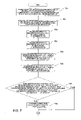
- FIGS. 9A and 9B show a relation between a bandwidth and a wireless resource while the TDMA is used as an example.
- 10 time slots exist in 1 second, and 1 kbit or 3 kbits can be selectively stored in 1 time slot by changing a modulation system.
- the maximum bandwidth of this channel is 30 kbps.
- the modulation system is used in which 3 kbits are stored in each time slot, while in the case where the wireless environment is poor, the modulation system is used in which 1 kbit is stored in each time slot.
- consideration is given to a case where a requested bandwidth of 6 kbps is ensured.
- FIG. 9A shows an example of a case where the wireless environment is good. In the case where the wireless environment is good, 3 kbits can be stored in 1 time slot, and 2 time slots are occupied in order to ensure 6 kbits. Accordingly, the wireless resource usage rate becomes 0.2 (the number of used slots is 2, the number of all time slots is 10).
- FIG. 9B shows an example of a case where the wireless environment is poor. In the case where the wireless environment is poor, since only 1 kbit can be stored in 1 time slot, 6 time slots are occupied in order to ensure 6 kbps. Accordingly, the wireless resource usage rate becomes 0.6 (the number of used slots is 6, the number of all time slots is 10).
- 9B is the example in which the wireless environment is poor, and unless the wireless environment is changed, the modulation system in which 1 kbit is stored in 1 time slot is used, and 6 time slots are required in order to ensure the bandwidth of 6 kbps. Accordingly, although the bandwidth of 24 kbps exists, the wireless resource is insufficient, and the required 6 kbps can not be ensured.
- the QoS is ensured.
- the wireless environment is changed from hour to hour by phasing or shadowing, and a time can occur in which the requested bandwidth can not be ensured on the time axis.
- the QoS terminal is controlled to use more wireless resources, and this becomes a large load for the wireless resource. That is, the terminal hinders the QoS provision to another QoS-capable terminal.
- the invention has an object to provide admission control to perform the new call connection of a terminal and call connection to a handoff destination in view of wireless resources. Besides, the invention has an object to take measures to prevent a terminal having a high wireless resource usage rate from disturbing QoS to other terminals in a case where a wireless resource usage rate becomes high.
- the invention has an object to provide admission control in which a judgment as to whether or not QoS provision can be provided is made by using an index of a wireless resource usage rate, and which prevents that a call-connected QoS requesting terminal can not start QoS communication because of insufficiency of wireless resources.
- the invention has an object to increase QoS calls which can receive QoS provision.
- the invention has an object to call-connect a new QoS requesting terminal.
- An index of a wireless resource usage rate is provided.
- the index is managed for each terminal and each channel, and the judgment as to whether or not QoS can be provided is made by using the index.
- the index of the wireless resource usage rate is provided, a wireless resource available rate of a channel and a wireless resource usage rate necessary to ensure a requested bandwidth of a terminal requesting connection are compared with each other at the time of QoS call connection, and the QoS call connection is performed when the available rate is larger.
- the wireless resource usage rate of a channel is periodically calculated, and in a case where the wireless resource usage rate of the channel exceeds a first threshold value, wireless resource usage rates of respective QoS-capable terminals are calculated, and among the QoS-capable terminals, a terminal in which the wireless resource usage rate exceeds a second threshold value is changed to best effort.
- a wireless communication system includes a base station, and the base station uses a wireless resource usage rate as an index and judges whether or not QoS can be provided. Besides, at the time of new call connection of a terminal or call connection to a handoff destination, as to whether or not QoS can be provided, the base station makes a handoff possible/impossible judgment by comparing the remainder of the wireless resource of the channel with a wireless resource estimated to be occupied by the terminal at the time of QoS.
- the base station monitors the wireless resource usage rate of the channel, and in the case where the wireless resource usage rate exceeds the first threshold value, the QoS terminal in which the wireless resource usage rate exceeds the second threshold value is changed to best effort.
- the first threshold value is a threshold value which serves as an opportunity to cause the base station to start a processing of changing the QoS terminal in which the wireless resource usage rate exceeds the second threshold value to the best effort.
- the second threshold value is a threshold value which becomes a criterion of judgment as to whether or not the base station changes the QoS terminal to the best effort, and for example, the QoS terminal in which the wireless resource usage rate exceeds the second threshold value is changed to the best effort.
- the base station hands off the terminal to the another channel.
- a base station in a wireless communication system comprising the base station to communicate with a terminal by wireless and by time division multiplexing, and a node to perform best effort communication and QoS communication with the terminal through the base station,
- the base station comprises:
- a requested bandwidth storage part in which a first requested bandwidth requested by one or plurality of first terminals during QoS communication and a second requested bandwidth requested by a second terminal trying to perform QoS communication are stored for each terminal;
- a data rate reception management part that receives a data amount which the first and the second terminal can receive in each time slot from the terminals, which depends on changing the data amount stored in each time slot according to wireless environment, calculates a first and a second data rates which the first and the second terminals can receive by obtaining a time average value of the data amount for each terminal, and stores the data rates for each terminal;
- control part to control the base station
- control part obtains a wireless resource available rate, based on a first requested bandwidth B i which is stored in the requested bandwidth storage part and is requested by the first terminal i, and a first data rate R i which the first terminal i can receive and which is stored in the data rate reception management part, by a following expression:
- control part obtains a wireless resource usage rate of the second terminal necessary to ensure the second requested bandwidth B, by dividing the second requested bandwidth B which is stored in the requested bandwidth storage part and is requested by the second terminal by the second data rate R which the second terminal can receive and which is stored in the data rate reception management part, and
- control part transmits, with respect to the second terminal in which the wireless resource available rate is equal to or more than the wireless resource usage rate, a connection establishment request for QoS, for performing QoS communication between the second terminal and the node, to the node.
- a base station in a wireless communication system comprising the base station to communicate with a terminal by wireless and by code division multiplexing, and a node to perform best effort communication and QoS communication with the terminal through the base station,
- the base station comprises:
- an S/N management part to store a value of S/N of a pilot channel for each terminal
- an ROT management part to store a value of ROT (Rise Over Thermal) for each channel
- ROT is defined by a following expression (I 0 +N 0 )/N 0
- I 0 is total of received power from all terminals
- N 0 is thermal noise power
- a threshold value storage part to store a previously determined threshold value indicating an allowable upper limit of the ROT
- control part to control the base station
- control part obtains a wireless resource available rate, based on a value T of ROT of a channel stored in the ROT management part and a threshold value T 1 stored in the threshold value storage part, by a following expression: 1 ⁇ T/T 1 ,
- the control part obtains a wireless resource usage rate of the second terminal, which is necessary to ensure the requested bandwidth stored in the requested bandwidth storage part and is requested by the second terminal, by a following expression: A ⁇ P ⁇ T/T 1 , where, A is a ratio of total transmission power to transmission power of a pilot channel when the second terminal transmits data in the requested bandwidth, and uniquely determined according to the requested bandwidth, P is an S/N value of the pilot channel of the second terminal stored in the S/N management part, T is ROT of a channel stored in the ROT management part, and T 1 is a previously determined threshold value indicating an allowable upper limit of ROT, which is stored in the threshold value storage part, and
- control part transmits, with respect to the second terminal in which the wireless resource available rate is equal to on more than the wireless resource usage rate, a connection establishment request for QoS, for performing QoS communication between the second terminal and the node, to the node.
- a base station in a wireless communication system comprising the base station to communicate with a terminal by wireless, by time division multiplexing in a downward direction to the terminal, and by code division multiplexing in an upward direction from the terminal, and a node to perform best effort communication and QoS communication with the terminal through the base station,
- the base station comprises:
- a requested bandwidth storage part in which a first down requested bandwidth requested by one or plurality of first terminals during QoS communication, a second down requested bandwidth requested by a second terminal trying to perform QoS communication, and an up requested bandwidth are stored for each terminal;
- a data rate reception management part that receives a data amount which the first and the second terminals can receive in each time slot from the terminals, which depends on changing the data amount stored in each time slot according to wireless environment, calculates a first and a second data rates which the first and the second terminals can receive by obtaining a time average value of the data amount for each terminal, and stores the data rates for each terminal;
- an S/N management part to store a value of S/N of a pilot channel for each terminal
- an ROT management part to store a value of ROT (Rise Over Thermal) for each up channel
- a threshold value storage part to store a previously determined threshold value indicating an allowable upper limit of the ROT
- control part to control the base station
- control part obtains a down wireless resource available rate, based on a first down requested bandwidth B i which is stored in the requested bandwidth storage part and is requested by the first terminal i, and a first data rate R i which the first terminal i can receive and which is stored in the data rate reception management part, by a following expression:
- control part obtains a down wireless resource usage rate of the second terminal necessary to ensure the second requested bandwidth B, by dividing the second down requested bandwidth B which is stored in the requested bandwidth storage part and is requested by the second terminal by the second data rate R which the second terminal can receive and which is stored in the data rate reception management part,
- control part obtains an up wireless resource available rate, based on a value T of ROT of an up channel stored in the ROT management part and a threshold value T 1 stored in the threshold value storage part, by a following expression: 1 ⁇ T/T 1 ,
- the control part obtains an up wireless resource usage rate of the second terminal, which is necessary to ensure the up requested bandwidth stored in the requested bandwidth storage part and is requested by the second terminal, by a following expression: A ⁇ P ⁇ T/T 1 , where, A is a ratio of total transmission power to transmission power of a pilot channel when the second terminal transmits data in the up requested bandwidth, and uniquely determined according to the up requested bandwidth, P is an S/N value of the pilot channel of the second terminal stored in the S/N management part, T is ROT of an up channel stored in the ROT management part, and T 1 is a previously determined threshold value indicating an allowable upper limit of ROT, which is stored in the threshold value storage part, and
- a base station in a wireless communication system comprising the base station having a first and a second channels and communicating with a terminal by wireless and by time division multiplexing, and a node to perform best effort communication and QoS communication with the terminal, wherein
- the base station obtains a first wireless resource usage rate in the first channel, based on a first requested bandwidth B i requested by one or plurality of first terminals i during QoS communication through the first channel and a first data rate R i which the first terminal i can receive and which depends on changing a data amount stored in each time slot according to wireless environment, by a following expression:
- the base station obtains a second wireless resource usage rate of the second terminal, which is necessary to ensure a requested bandwidth B, by dividing the second requested bandwidth B requested by an arbitrary second terminal during QoS communication through the first channel by a second data rate R which the second terminal can receive,
- the base station obtains a predicted value of a wireless resource usage rate in the first channel after the second terminal hands off to the second channel by subtracting the second wireless resource usage rate of the second terminal from the first wireless resource usage rate in the first channel,
- the base station obtains a third wireless resource usage rate in the second channel, based on a third requested bandwidth B k requested by one or plurality of third terminals k during QoS communication through the second channel and a third data rate R k which the third terminal k can receive, which depends on changing a data amount stored in each time slot according to wireless environment, by a following expression:
- the base station obtains a fourth wireless resource usage rate of the second terminal after the second terminal hands off to the second channel, by dividing the second requested bandwidth B requested by the second terminal by an average R AVE of the data rate which each terminal communicating through the second channel can receive,
- the base station obtains a predicted value of a wireless resource usage rate in the second channel after the second terminal hands off to the second channel by adding the fourth wireless resource usage rate in the second terminal to the third wireless resource usage rate in the second channel, and
- a base station in a wireless communication system comprising the base station having a first and a second channels and communicating with a terminal by wireless and by code division multiplexing, and a node to perform best effort communication and QoS communication with the terminal, wherein
- the base station obtains a first wireless resource usage rate in the first channel, by dividing ROT (Rise Over Thermal) T a of the first channel by a previously determined first ROT threshold value T 1 indicating an allowable upper limit of the ROT,
- the base station obtains a second wireless resource usage rate of the second terminal, which is necessary to ensure a requested bandwidth requested by an arbitrary second terminal during QoS communication through the first channel, by a following expression: A ⁇ P ⁇ T a /T 1 , where, A is a ratio of total transmission power to transmission power of a pilot channel when the second terminal transmits data in the requested bandwidth, and uniquely determined according to the requested bandwidth, P is S/N of the pilot channel of the second terminal, T a is ROT of the first channel, and T 1 is a previously determined first ROT threshold value indicating an allowable upper limit of ROT,
- the base station obtains a predicted value of a wireless resource usage rate in the first channel after the second terminal hands off to the second channel by subtracting the second wireless resource usage rate in the second terminal from the first wireless resource usage rate in the first channel,
- the base station obtains a third wireless resource usage rate in the second channel, by dividing ROT T b of the second channel by a previously determined second threshold value T 2 indicating an allowable upper limit of the ROT,
- the base station obtains a fourth wireless resource usage rate of the second terminal after the second terminal hands off to the second channel by a following expression: A ⁇ P AVE ⁇ T b /T 2 , where, A is a ratio of total transmission power to transmission power of the pilot channel when the second terminal transmits data in the requested bandwidth, and uniquely determined according to the requested bandwidth, P AVE is an average of S/N of the pilot channel of all terminals communicating through the second channel, T b is ROT of the second channel, and T 2 is a previously determined second ROT threshold value indicating an allowable upper limit of the ROT,
- the base station obtains a predicted value of a wireless resource usage rate in the second channel after the second terminal hands off to the second channel by adding the fourth wireless resource usage rate in the second terminal to the third wireless resource usage rate in the second channel, and
- a wireless communication system comprising:
- a base station to communicate with a terminal by wireless and by time division multiplexing
- a node that has a QoS information table in which a requested bandwidth requested by the terminal is previously stored correspondingly to an identifier of the terminal and performs best effort communication and QoS communication with the terminal through the base station,
- the base station comprises:
- a requested bandwidth storage part in which a first requested bandwidth requested by one or plurality of first terminals during QoS communication and a second requested bandwidth requested by a second terminal trying to perform QoS communication are stored for each terminal;
- a data rate reception management part that receives a data amount which the first and the second terminals can receive in each time slot from the terminals, which depends on changing the data amount stored in each time slot according to wireless environment, calculates a first and a second data rates which the first and the second terminals can receive by obtaining a time average value of the data amount for each terminal, and stores the data rates for each terminal;
- control part to control the base station
- the node receives a connection establishment request for best effort, which includes an identifier of the second terminal trying to perform QoS communication, from the base station, and previously establishes connection for best effort between the second terminal and the node, and
- the node refers to the QoS information table and transmits a second requested bandwidth corresponding to the identifier of the second terminal included in the establishment request to the base station,
- control part stores the second requested bandwidth received from the node into the requested bandwidth storage part
- control part obtains a wireless resource available rate, based on a first requested bandwidth B i which is stored in the requested bandwidth storage part and is requested by the first terminal i and a first data rate R i which the first terminal i can receive and which is stored in the data rate reception management part, by a following expression:
- control part obtains a wireless resource usage rate of the second terminal, which is necessary to ensure the second requested bandwidth B, by dividing the second requested bandwidth B which is stored in the requested bandwidth storage part and is requested by the second terminal by the second data rate R which the second terminal can receive and which is stored in the data rate reception management part, and
- a wireless communication system comprising:
- a base station to communicate with a terminal by wireless and by code division multiplexing
- a node that has a QoS information table in which a requested bandwidth requested by the terminal is previously stored correspondingly to an identifier of the terminal and performs best effort communication and QoS communication with the terminal through the base station,
- the base station comprises:
- an S/N management part to store a value of S/N of a pilot channel for each terminal
- an ROT management part to store a value of ROT (Rise Over Thermal) for each channel
- a threshold value storage part to store a previously determined threshold value indicating an allowable upper limit of the ROT
- control part to control the base station
- the node receives a connection establishment request for best effort, which includes an identifier of a second terminal trying to perform QoS communication, from the base station, and previously establishes connection for best effort between the second terminal and the node, and
- the node refers to the QoS information table and transmits a requested bandwidth corresponding to the identifier of the second terminal included in the establishment request to the base station,
- control part stores the second requested bandwidth received from the node into the requested bandwidth storage part
- control part obtains a wireless resource available rate, based on a value T of ROT of a channel stored in the ROT management part and a threshold value T 1 stored in the threshold value storage part, by a following expression: 1 ⁇ T/T 1 ,
- the control part obtains a wireless resource usage rate of the second terminal, which is necessary to ensure a requested bandwidth stored in the requested bandwidth storage part and is requested by the second terminal, by a following expression: A ⁇ P ⁇ T/T 1 , where, A is a ratio of total transmission power to transmission power of a pilot channel when the second terminal transmits data in the requested bandwidth, and uniquely determined according to the requested bandwidth, P is an S/N value of the pilot channel of the second terminal stored in the S/N management part, T is ROT of a channel stored in the ROT management part, and T 1 is a previously determined threshold value indicating an allowable upper limit of ROT, which is stored in the threshold value storage part, and
- the admission control to perform the new call connection of a terminal and call connection to a handoff destination in view of the wireless resources.
- measures can be taken to prevent a terminal having a high wireless resource usage rate from disturbing the QoS of another terminal.
- the admission control in which the judgment as to whether or not the QoS can be provided is made by using the index of the wireless resource usage rate, and which prevents that a call-connected QoS requesting terminal can not start the QoS communication because of insufficiency of wireless resources.
- QoS calls which can receive the QoS provision can be increased. According to the invention, it becomes possible to call-connect a new QoS requesting terminal.
- FIG. 1 is a system structural view of a wireless information communication system to which the invention is applied.
- FIG. 2 is a functional block diagram of a base station in the wireless information communication system to which the invention is applied.
- FIGS. 3A and 3B show data formats (1) of respective blocks of the base station.
- FIGS. 4A and 4B show data formats (2) of respective blocks of the base station.
- FIG. 5 shows an example of a QoS information table owned by PDSN.
- FIG. 6 is a sequence view of connection establishment at a time of new call connection of a terminal or at a time of call connection to a handoff destination in the wireless information communication system to which the invention is applied.
- FIG. 7 is a flowchart relating to one of solving means of the invention.
- FIG. 8 is a flowchart relating to another solving means of the invention.
- FIGS. 9A and 9B are views showing a relation between a bandwidth and a wireless resource while TDMA is used as an example.
- FIG. 1 is a view showing an example of a system structure of the 1xEV-DO system.
- the 1xEV-DO system includes, for example, terminals 110 , base stations 120 , an IP-SW (IP Switch) 130 , and a PDSN (Packet Data Serving Node) 140 .
- the PDSN 140 is connected to the Internet 150 .
- the PDSN includes a QoS information table 141 .
- Wireless communication is provided between the base station 120 and the terminal 110 , and is indicated by a broken line in the figure.
- a solid line in the figure indicates cable communication.
- transmission (down) from the base station 120 to the terminal 110 is TDMA communication
- transmission (up) from the terminal 110 to the base station 120 is CDMA communication.
- Plural channels exist in each of the down transmission and the up transmission.
- FIG. 2 is a functional block diagram of the base station 120 in this embodiment. Besides, FIGS. 3A and 3B and FIGS. 4A and 4B show data formats of respective blocks of the base station 120 .
- the base station 120 includes a requested bandwidth storage part 510 , a ROT (Rise Over Thermal) threshold value storage part 520 , a control part 530 , a handoff instruction part 540 , a receivable data rate reception-management part 550 , an S/N reception-management part 560 , a ROT reception-management part 570 , and a channel management part 580 .
- ROT Random Over Thermal
- a down QoS requested bandwidth of a terminal i to which a call is connected, an up QoS requested bandwidth, and a value of a ratio A i of the total transmission power to transmission power of a pilot channel when the terminal i transmits data in the up QoS requested bandwidth are stored for each of the terminals 110 .
- the down and up QoS requested bandwidths of each terminal 110 to perform the QoS communication are acquired from the QoS information table 141 of the PDSN 140 and are stored in the requested bandwidth storage part 510 .
- FIG. 3A shows an example of a table structure. For example, with respect to each channel managed by the base station 120 , each data is stored (the figure shows an example of a channel 1 ).
- a previously set ROT threshold value is stored in the ROT threshold value storage part 520 .
- the ROT threshold value may be stored for each channel.
- the handoff instruction part 540 transmits, to the terminal 110 , an instruction to perform handoff to a specified different channel.
- the receivable data rate reception-management part 550 receives, for each terminal 110 , a data rate (data amount per 1 time slot) receivable in 1 time slot of the terminal 110 from the terminal 110 . Besides, the receivable data rate reception-management part 550 calculates a time average value R i for each terminal i, obtains the data rate which the terminal 110 can receive, and manages and stores it.
- the time average value R i can be made, for example, a data rate (bps) per 1 second.
- FIG. 3B shows an example of a table structure. For example, with respect to each channel managed by the base station 120 , each data is stored (the figure shows an example of the channel 1 ).
- the S/N reception-management part 560 receives the S/N of a pilot channel for each terminal 110 , and stores, for example, the S/N correspondingly to an identifier of the terminal 110 . It is received from, for example, a suitable block (not shown) in the base station 120 to receive the pilot channel.
- FIG. 4A shows an example of a table structure. For example, with respect to each channel managed by the base station 120 , each data is stored (the figure shows an example of the channel 1 ).
- the ROT reception-management part 570 receives the ROT for each up channel, and stores the ROT correspondingly to, for example, an identifier of a channel. For example, it is received from a suitable block (not shown) in the base station 120 to obtain the ROT.
- FIG. 4B shows an example of a table structure.
- the channel management part 580 manages channels provided by the base station 120 .
- FIG. 5 shows the QoS information table 141 stored in the PDSN 140 .
- the PDSN 140 includes the QoS information table 141 in which QoS information is previously stored correspondingly to a terminal registration number. For example, it is stored in a suitable memory or the like.
- the QoS information includes, for example, a down QoS requested bandwidth and an up QoS requested bandwidth.
- a suitable identifier to identify the terminal 110 can be used as the terminal registration number.
- no data may be stored, or previously determined specific data, such as zero or null, may be stored.
- the wireless resource usage rate in this embodiment will be defined.
- the wireless resource usage rate is a time slot allocation rate. For example, as in FIG. 9A , when 2 time slots are used in a channel having 10 time slots per 1 second, the wireless resource usage rate is 0.2.
- the terminal 110 transmits a data rate which can be received in each time slot to the base station 120 , and in the base station 120 , a value R i obtained by time-averaging that is managed in the receivable data rate reception-management part 550 .
- the slot allocation rate of the ith terminal 110 in the channel becomes B i /R i (1) by using the down QoS requested bandwidth B i of the ith terminal and the average R i of the data rate which the terminal 110 can receive.
- the slot allocation rate of all channels becomes as follows.
- the up transmission is the CDMA communication
- the ROT is used as the index of the wireless resource usage rate of a channel.
- T the value of the ROT
- T 1 the value stored in the ROT threshold value storage part 520 can be used.
- the wireless resource usage rate of the ith terminal 110 in the channel is the extent of contribution of the terminal 110 in the ROT of all the channels, and becomes as follows.
- Ai denotes the ratio of the total transmission power to the transmission power of the pilot channel when the terminal i transmits data in the up QoS requested bandwidth, and has a unique correspondence relation to the up QoS requested bandwidth.
- Pi denotes the S/N of the pilot channel of the terminal i which the base station 120 receives. Ai is uniquely obtained based on the QoS requested bandwidth and is stored in the requested bandwidth storage part 510 . Pi is received and stored in the S/N reception-management part 560 .
- FIG. 6 is a sequence view of connection establishment at the time of new call connection or at the time of call connection to a handoff destination.
- a negotiation for communication start is performed between the terminal 110 and the base station 120 (processing 201 ).
- the terminal 110 transmits a terminal registration number to the base station 120 , and the base station 120 assigns an identification ID to the terminal 110 .
- the terminal registration number is previously stored in the terminal 110 .
- the base station 120 transmits a connection establishment request for best effort to the PDSN 140 (processing 202 ).
- the connection establishment request for best effort includes the terminal registration number received from the terminal 110 .
- the PDSN 140 transmits a connection establishment response for best effort to the base station 120 (processing 203 ).
- the connection for best effort is established between the terminal 110 and the PDSN 140 , and the terminal 110 can communicate with the Internet through the best effort (processing 204 ).
- both a QoS terminal and a non-QoS terminal are first connected through the best effort.
- the PDSN 140 After the connection for best effort is established, the PDSN 140 refers to the QoS information table 141 based on the terminal registration number received in the foregoing processing 202 , and acquires a down QoS requested bandwidth and an up QoS requested bandwidth corresponding to the terminal registration number. For example, in the case where the connected terminal 110 is the QoS request terminal, the down and up QoS requested bandwidths are stored in the QoS information table 141 , and the others are not stored therein. When acquiring the down and up QoS requested bandwidths, the PDSN 140 transmits a connection establishment instruction for QoS to the base station 120 (processing 205 ).
- the connection establishment instruction for QoS includes the down QoS requested bandwidth and the up QoS requested bandwidth of the connected terminal 110 . Further, it may include a terminal registration number. On the other hand, the down and up QoS requested bandwidths are not stored and can not be acquired, the PDSN 140 terminates the processing. In this case, the communication in best effort is continued between the terminal 110 and the PDSN 140 .
- FIG. 7 is a flowchart of the operation of the base station 120 having received the connection establishment instruction for QoS.
- the base station 120 having received the connection establishment instruction for QoS stores the value of the down QoS requested bandwidth and the value of the up QoS requested bandwidth included therein into the requested bandwidth storage part 510 (processing 701 ). They may be stored correspondingly to, for example, the terminal registration number received in processing 201 or the terminal registration number included in the connection establishment instruction for QoS.
- the base station 120 obtains the value of A i from the QoS requested bandwidth uniquely, and similarly stores it into the requested bandwidth storage part 510 (processing 702 ).
- the way of obtaining the value of A i may be a previously determined suitable method such as a conventional method.
- the base station 120 calculates, with respect to each of the up and down transmissions, the wireless resource available rate of the channel through which the best effort call of the terminal 110 is provided (processing 703 , processing 704 ).
- the wireless resource available rate of the channel is obtained from the wireless resource usage rate of 1 channel.
- the wireless resource usage rate of the channel in the down transmission is calculated by the foregoing expression (2) using the down QoS requested bandwidth B i of each terminal i stored in the requested bandwidth storage part 510 and the time average R i of the receivable data rate of each terminal i managed by the receivable data rate reception-management part 550 .
- the wireless resource usage rate in the up transmission is calculated by expression (3) using the ROT threshold value T 1 stored in the ROT threshold value storage part 520 and the value T of ROT received in the ROT reception-management part 570 . That is, the wireless resource available rate of the down channel is
- the wireless resource available rate of the up channel is 1 ⁇ T/T 1 where, i denotes all terminals (first terminals) which perform QoS communication with the base station 120 .
- the base station 120 calculates the wireless resource usage rate necessary for the terminal (second terminal) negotiated in processing 201 to ensure the QoS requested bandwidth.
- the wireless resource usage rate of the terminal 110 in the down transmission is calculated by the foregoing expression (1) using the down QoS requested bandwidth B i of the terminal 110 stored in the requested bandwidth storage part 510 and the time average R i of the receivable data rate of the terminal 110 managed by the receivable data rate reception-management part 550 (processing 705 ).
- the base station 120 acquires the corresponding down QoS requested bandwidth B from the requested bandwidth storage part 510 based on the terminal registration number received in processing 201 or the terminal registration number included in the connection establishment instruction for QoS received in processing 205 .
- the down QoS requested bandwidth received in processing 205 may be used.
- the base station 120 acquires the corresponding data rate R from the receivable data rate reception-management part 550 based on the received terminal registration number.
- the base station 120 calculates B/R in accordance with the acquired values, and obtains the down wireless resource usage rate of the terminal 110 necessary to ensure the down QoS requested bandwidth B.
- the base station 120 calculates the up wireless resource usage rate of the terminal 110 by multiplying the wireless resource usage rate (T/T 1 ) of the channel by S/N (P i ) of the pilot channel for each terminal 110 of the S/N reception-management part 560 and A i for each terminal 110 stored in the requested bandwidth storage part 510 (processing 706 ). That is, the calculation is performed by the foregoing expression (4).
- the base station 120 (for example, the control part 530 ) acquires the corresponding S/N value from the S/N reception-management part 560 based on the terminal registration number received in processing 201 or the terminal registration number included in the connection establishment instruction for QoS and received in processing 205 , and acquires A i corresponding to the foregoing terminal registration number from the requested bandwidth storage part 510 .
- the base station 120 acquires the ROT threshold value T 1 stored in the ROT threshold value storage part 520 and the value of ROT, stored in the ROT reception-management part 570 , of the channel through which the terminal 110 communicates.
- the base station 120 obtains the up wireless resource usage rate of the terminal 110 by expression (4).
- the base station 120 judges whether the wireless resource available rate of the channel is larger than the necessary wireless resource usage rate in both the up and down transmissions (processing 707 ), and when larger in both the up and down transmissions, the connection establishment instruction for QoS is transmitted to the PDSN 140 (processing 708 , FIG. 6 : processing 206 ).
- the base station 120 does not transmit the connection establishment instruction for QoS to the PDSN 140 , and terminates the processing.
- the terminal 110 continues the communication while maintaining the best effort.
- the base station 120 may repeat the foregoing processings 703 to 708 with respect to another channel. In the case where the necessary wireless resource usage rate is equal to the wireless resource available rate of the channel, the connection establishment instruction for QoS may be transmitted, or the processing may be terminated.
- the PDSN 140 having received the connection establishment instruction for QoS transmits the connection establishment response for QoS to the base station 120 (processing 207 ).
- the connection for QoS is established between the terminal 110 and the PDSN 140 (processing 208 ).
- identifiers which can identify the down transmission, the up transmission and both the transmissions are made to be included in the connection establishment instruction for QoS, and QoS communication may be performed only in one of the up and down transmissions in which the wireless resource available rate of the channel is larger than the necessary wireless resource usage rate.
- an identifier indicating a direction (up or down) of a channel in which the wireless resource available rate of the channel is larger, and the connection establishment instruction for QoS are transmitted to the PDSN 140 , and the connection for QoS may be established only in the single direction corresponding to the identifier.
- the connection establishment instruction for QoS can be transmitted to the PDSN 140 at the stage of processing 202 .
- the up and down QoS requested bandwidths are acquired from the QoS information table owned by the base station 120 , and the QoS provision possible/impossible calculation (processing 702 to processing 708 ) is performed, and when the QoS can be provided, processing 202 to processing 205 are not performed, but the connection establishment instruction for QoS is transmitted to the PDSN 140 from the first (processing 206 ).
- the connection establishment request for best effort can also be transmitted to the PDSN 140 as in processing 202 .
- connection for QoS in both the up and down transmissions may be established only in the case where the QoS can be provided in both the up and down transmissions, or connection for QoS may be established only in one side when the QoS can be provided only in the one side.
- call connection may be rejected, or a connection establishment request for best effort is transmitted to the PDSN 140 and the connection for best effort may be established.
- the first embodiment relates to the processing at the time of new connection and the time of connection by handoff, while the second embodiment relates to a processing on a connected terminal 110 .
- a following processing is periodically performed.
- FIG. 8 is a flowchart in the second embodiment.
- a base station 120 periodically performs respective processings of the flowchart of FIG. 8 .
- the flow of the processing will be described in brief.
- the wireless resource usage rate of a channel is calculated using the foregoing expressions (2) and (3) (processing 401 ).
- a first threshold value for example, 1
- the base station 120 obtains the wireless resource usage rate of the terminal 110 performing the QoS communication in the channel by, for example, the expression (1) for the down transmission and by the expression (4) for the up transmission (processings 403 and 404 ), and it is checked whether there is a terminal in which the wireless resource usage rate exceeds a second threshold value (for example, 1) (processing 405 ).
- the base station 120 changes the terminal 110 in such a state to the best effort communication (processing 406 ). For example, by the change of the wireless environment, there can occur a case where the requested bandwidth can not be ensured according to the time.
- the base station 120 repeats the foregoing processings 404 to 406 on all terminals 110 in which the QoS communication is performed (processing 407 ).
- the base station 120 confirms whether another channel exists (processing 409 ).
- the another channel is, for example, a channel of another frequency, and information, such as ROT of the channel, a QoS requested bandwidth of the terminal 110 communicating through the channel, S/N, and a data rate, is managed in the respective blocks of the base station 120 .
- the base station 120 calculates whether or not, in the case where the terminal 110 is handed off to the another channel in the descending order of magnitude of the wireless resource usage rate of the terminal 110 , the wireless resource usage rates of both the handoff source channel (first channel) after the handoff and the handoff destination channel (second channel) become smaller than 1 (processings 412 to 414 ).
- the wireless resource usage rate of the handoff source after the handoff is calculated by, for example, wireless resource usage rate of channel of handoff source before handoff ⁇ wireless resource usage rate of terminal before handoff.
- the wireless resource usage rate of the channel of the handoff source before the handoff for example, the value obtained in processing 401 can be used.
- the wireless resource usage rate of the terminal 110 before the handoff for example, the value obtained in processing 404 can be used.
- the wireless resource usage rate of the handoff destination after the handoff is calculated by, for example, wireless resource usage rate of channel of handoff destination before handoff+wireless resource usage rate of terminal after handoff.
- the wireless resource usage rate of the channel of the handoff destination before the handoff for example, with respect to the channel of the handoff destination, values obtained by the foregoing expression (2) and expression (3) can be used.
- the expression (5) can be used for the down transmission
- the expression (6) can be used for the up transmission. The detailed processing of processings 412 and 413 will be described later.
- the base station 120 transmits the handoff instruction including identification information to identify the channel of the handoff destination from the handoff instruction part 540 to the terminal 110 , and hands off the terminal 110 to the channel of the handoff destination (processing 415 ).
- the terminal 110 is changed and the processing is repeatedly performed until the wireless resource usage rate of the channel becomes 1 or less or it is found that there is no terminal 110 which can be handed off (processing 411 to processing 418 ).
- processing 411 to processing 418 the processing is changed and the processing is repeated (processing 410 to processing 419 ).
- the processing is terminated.
- processing 417 the processing exits from the repeated processing (processing 410 to processing 419 ) and is terminated.
- the first threshold value of the wireless resource usage rate of the channel which serves as an opportunity to change the communication of the terminal 110 to the best effort, is made 1
- another value may be set as the threshold value.
- the second threshold value of the wireless resource usage rate of the terminal 110 which serves as an opportunity to hand off the terminal 110 , is made 1
- another value may be set as the threshold value.
- processing 412 to processing 415 of FIG. 8 to hand off the terminal 110 to another channel will be described below in detail.
- both the up and down processings may be performed in parallel, or may be performed in series.
- only the down processing or only the up processing may be performed.
- the base station 120 obtains a first down wireless resource usage rate in the first channel by the following expression.
- values stored in the requested bandwidth storage part 510 and the receivable data rate reception/management part 550 can be used. The same applies to a subsequent processing.
- the base station 120 obtains a second down wireless resource usage rate of the second terminal, which is necessary to ensure the down QoS requested bandwidth B, by dividing the second down QoS requested bandwidth B requested by an arbitrary second terminal (for example, one of the first terminals) during QoS communication through the first channel by the second data rate R which the second terminal can receive.
- the base station 120 obtains a predicted value of a down wireless resource usage rate in the first channel after the second terminal is handed off to the second channel by subtracting the second down wireless resource usage rate of the second terminal from the obtained first down wireless resource usage rate in the first channel. That is, the predicted value of the down wireless resource usage rate of the handoff source (first channel) after the handoff is expressed by the following expression.
- processing 413 first, based on a third down QoS requested bandwidth B k requested by one or plural third terminals k during QoS communication in the second channel, and a third data rate R k
- the base station 120 obtains a third down wireless resource usage rate in the second channel by the following expression.
- the base station 120 obtains a fourth down wireless resource usage rate of the second terminal after the second terminal hands off to the second channel by dividing the second down QoS requested bandwidth B requested by the second terminal by the average R AVE of the third data rate Rp (B/R AVE ) which each terminal 110 communicating through the second channel can receive.
- the base station 120 obtains a predicted value of a down wireless resource usage rate in the second channel after the second terminal hands off to the second channel by adding the fourth down wireless resource usage rate of the second terminal to the third down wireless resource usage rate in the second channel. That is, the predicted value of the down wireless resource usage rate of the handoff destination (second channel) after the handoff is expressed by the following expression.
- the base station 120 obtains a first up wireless resource usage rate in the first channel by dividing ROT (Rise Over Thermal) T a of the first channel by a previously determined first threshold value T 1 indicating an allowable upper limit of the ROT (T a /T 1 ).
- ROT Radial Over Thermal
- T 1 a previously determined first threshold value indicating an allowable upper limit of the ROT (T a /T 1 ).
- values stored in the ROT reception/management part 570 and the ROT threshold value storage part 520 can be used.
- the base station 120 obtains a second up wireless resource usage rate of the second terminal necessary to ensure an up QoS requested bandwidth requested by an arbitrary second terminal i during QoS communication through the first channel by the following expression: A ⁇ P ⁇ T a /T 1 where, A: a ratio of the total transmission power to transmission power of a pilot channel when the second terminal transmits data in the up QoS requested bandwidth, which is a value uniquely determined according to the up QoS requested bandwidth, P: S/N of the pilot channel of the second terminal, T a : ROT of the first channel, and T 1 : previously determined first threshold value indicating the allowable upper limit of ROT.
- the base station 120 obtains a third up wireless resource usage rate in the second channel by dividing ROT (T b ) of the second channel by a previously determined second threshold value T 2 indicating an allowable upper limit of the ROT (T b /T 2 ).
- the base station 120 obtains a fourth up wireless resource usage rate of the second terminal after the second terminal hands off to the second channel by the following expression: A ⁇ P AVE ⁇ T b /T 2 where, A: a ratio of the total transmission power to transmission power of the pilot channel when the second terminal transmits data in the up QoS requested bandwidth, which is a value uniquely determined according to the up QoS requested bandwidth, P AVE : an average of S/N of the pilot channel of all the terminals 110 communicating through the second channel, T b : ROT of the second channel, and T 2 : a previously determined second threshold value indicating an allowable upper limit of ROT.
- the base station 120 hands off the second terminal from the first channel to the second channel.
- the first embodiment and the second embodiment are combined, and for example, after the communication is started in the first embodiment, the second embodiment may be performed.
- the invention can be applied also to the case where the up transmission is the TDMA.
- the description has been given to the case where the up transmission is the CDMA, the invention can be applied also to the case where the down transmission is the CDMA.
- the invention can be used for the industry relating to the communication system to provide QoS, and the communication service.
Abstract
Description
(I0+N0)/N0
1−T/T1,
A×P×T/T1,
where, A is a ratio of total transmission power to transmission power of a pilot channel when the second terminal transmits data in the requested bandwidth, and uniquely determined according to the requested bandwidth, P is an S/N value of the pilot channel of the second terminal stored in the S/N management part, T is ROT of a channel stored in the ROT management part, and T1 is a previously determined threshold value indicating an allowable upper limit of ROT, which is stored in the threshold value storage part, and
1−T/T1,
A×P×T/T1,
where, A is a ratio of total transmission power to transmission power of a pilot channel when the second terminal transmits data in the up requested bandwidth, and uniquely determined according to the up requested bandwidth, P is an S/N value of the pilot channel of the second terminal stored in the S/N management part, T is ROT of an up channel stored in the ROT management part, and T1 is a previously determined threshold value indicating an allowable upper limit of ROT, which is stored in the threshold value storage part, and
-
- the control part transmits, with respect to the second terminal in which the down wireless resource available rate is equal to or more than the wireless resource usage rate, and in which the up wireless resource available rate is equal to or more than the up wireless resource usage rate, a connection establishment request for QoS, for performing QoS communication between the second terminal and the node, to the node.
-
- the base station hands off the second terminal from the first channel to the second channel in a case where both the obtained predicted value of the wireless resource usage rate in the first channel and the predicted value of the wireless resource usage rate in the second channel respectively become equal to or less than previously determined threshold values.
A×P×Ta/T1,
where, A is a ratio of total transmission power to transmission power of a pilot channel when the second terminal transmits data in the requested bandwidth, and uniquely determined according to the requested bandwidth, P is S/N of the pilot channel of the second terminal, Ta is ROT of the first channel, and T1 is a previously determined first ROT threshold value indicating an allowable upper limit of ROT,
A×PAVE×Tb/T2,
where, A is a ratio of total transmission power to transmission power of the pilot channel when the second terminal transmits data in the requested bandwidth, and uniquely determined according to the requested bandwidth, PAVE is an average of S/N of the pilot channel of all terminals communicating through the second channel, Tb is ROT of the second channel, and T2 is a previously determined second ROT threshold value indicating an allowable upper limit of the ROT,
-
- the base station hands off the second terminal from the first channel to the second channel in a case where both the obtained predicted value of the wireless resource usage rate in the first channel and the predicted value of the wireless resource usage rate in the second channel respectively become equal to or less than previously determined threshold values.
-
- the control part transmits, with respect to the second terminal in which the wireless resource available rate is equal to or more than the wireless resource usage rate, a connection establishment request for QoS, for performing QoS communication between the second terminal and the node, to the node.
1−T/T1,
A×P×T/T1,
where, A is a ratio of total transmission power to transmission power of a pilot channel when the second terminal transmits data in the requested bandwidth, and uniquely determined according to the requested bandwidth, P is an S/N value of the pilot channel of the second terminal stored in the S/N management part, T is ROT of a channel stored in the ROT management part, and T1 is a previously determined threshold value indicating an allowable upper limit of ROT, which is stored in the threshold value storage part, and
-
- the control part transmits, with respect to the second terminal in which the wireless resource available rate is equal to or more than the wireless resource usage rate, a connection establishment request for QoS, for performing QoS communication between the second terminal and the node, to the node.
Bi/Ri (1)
by using the down QoS requested bandwidth Bi of the ith terminal and the average Ri of the data rate which the terminal 110 can receive.
T/T1 (3)
Incidentally, as the value T of the ROT, the value received and stored by the ROT reception-
Here, Ai denotes the ratio of the total transmission power to the transmission power of the pilot channel when the terminal i transmits data in the up QoS requested bandwidth, and has a unique correspondence relation to the up QoS requested bandwidth. Pi denotes the S/N of the pilot channel of the terminal i which the
(Operation)
and the wireless resource available rate of the up channel is
1−T/T1
where, i denotes all terminals (first terminals) which perform QoS communication with the
Bi/RAVE (5)
On the other hand, in the up transmission, the following expression may be used in which an average PAVE of S/N of pilot signals received in the
wireless resource usage rate of channel of handoff source before handoff−wireless resource usage rate of terminal before handoff. (7)
As the wireless resource usage rate of the channel of the handoff source before the handoff, for example, the value obtained in
wireless resource usage rate of channel of handoff destination before handoff+wireless resource usage rate of terminal after handoff. (8)
As the wireless resource usage rate of the channel of the handoff destination before the handoff, for example, with respect to the channel of the handoff destination, values obtained by the foregoing expression (2) and expression (3) can be used. As the wireless resource usage rate of the terminal 110 after the handoff, the expression (5) can be used for the down transmission, and the expression (6) can be used for the up transmission. The detailed processing of
which the third terminal k can receive and which depends on data amount stored in each time slot and changed according to wireless environment, the
down wireless resource usage rate in the first channel and the predicted value of the down wireless resource usage rate in the second channel respectively become the previously determined threshold values (for example, 1) or less (processing 414), the
A×P×Ta/T1
where, A: a ratio of the total transmission power to transmission power of a pilot channel when the second terminal transmits data in the up QoS requested bandwidth, which is a value uniquely determined according to the up QoS requested bandwidth, P: S/N of the pilot channel of the second terminal, Ta: ROT of the first channel, and T1: previously determined first threshold value indicating the allowable upper limit of ROT.
predicted value=T a /T 1 −A×P×T a /T 1. (7″)
A×PAVE×Tb/T2
where, A: a ratio of the total transmission power to transmission power of the pilot channel when the second terminal transmits data in the up QoS requested bandwidth, which is a value uniquely determined according to the up QoS requested bandwidth, PAVE: an average of S/N of the pilot channel of all the
predicted value=T b /T 2 +A×P AVE ×T b /T 2. (8″)
Claims (7)
1−T/T1,
A×P×T/T1,
1−T/T1,
A×P×T/T1,
1−T/T1,
A×P×T/T1,
Priority Applications (2)
| Application Number | Priority Date | Filing Date | Title |
|---|---|---|---|
| US12/603,617 US7912478B2 (en) | 2005-10-13 | 2009-10-22 | Wireless communication system and base station |
| US12/603,621 US7907951B2 (en) | 2005-10-13 | 2009-10-22 | Wireless communication system and base station |
Applications Claiming Priority (2)
| Application Number | Priority Date | Filing Date | Title |
|---|---|---|---|
| JP2005298425A JP4612523B2 (en) | 2005-10-13 | 2005-10-13 | Wireless communication system and base station |
| JP2005-298425 | 2005-10-13 |
Related Child Applications (2)
| Application Number | Title | Priority Date | Filing Date |
|---|---|---|---|
| US12/603,617 Division US7912478B2 (en) | 2005-10-13 | 2009-10-22 | Wireless communication system and base station |
| US12/603,621 Division US7907951B2 (en) | 2005-10-13 | 2009-10-22 | Wireless communication system and base station |
Publications (2)
| Publication Number | Publication Date |
|---|---|
| US20070086379A1 US20070086379A1 (en) | 2007-04-19 |
| US7634278B2 true US7634278B2 (en) | 2009-12-15 |
Family
ID=37948062
Family Applications (3)
| Application Number | Title | Priority Date | Filing Date |
|---|---|---|---|
| US11/476,058 Expired - Fee Related US7634278B2 (en) | 2005-10-13 | 2006-06-28 | Wireless communication system and base station |
| US12/603,617 Active US7912478B2 (en) | 2005-10-13 | 2009-10-22 | Wireless communication system and base station |
| US12/603,621 Active US7907951B2 (en) | 2005-10-13 | 2009-10-22 | Wireless communication system and base station |
Family Applications After (2)
| Application Number | Title | Priority Date | Filing Date |
|---|---|---|---|
| US12/603,617 Active US7912478B2 (en) | 2005-10-13 | 2009-10-22 | Wireless communication system and base station |
| US12/603,621 Active US7907951B2 (en) | 2005-10-13 | 2009-10-22 | Wireless communication system and base station |
Country Status (3)
| Country | Link |
|---|---|
| US (3) | US7634278B2 (en) |
| JP (1) | JP4612523B2 (en) |
| CN (1) | CN1949899B (en) |
Cited By (4)
| Publication number | Priority date | Publication date | Assignee | Title |
|---|---|---|---|---|
| US20080076464A1 (en) * | 2006-09-22 | 2008-03-27 | Mitsubishi Electric Corporation | Method and device for transferring signals representative of a pilot symbol pattern |
| US20080316960A1 (en) * | 2007-06-22 | 2008-12-25 | At&T Intellectual Property, Inc. | Regulating network service levels provided to communication terminals through a LAN access point |
| US20090054072A1 (en) * | 2007-08-20 | 2009-02-26 | Futurewei Technologies, Inc. | System For QOS Aware Reverse Link Admission Control In Wireless Communication Systems |
| US20120057500A1 (en) * | 2009-05-13 | 2012-03-08 | Kyocera Corporation | Radio base station and communication control method |
Families Citing this family (30)
| Publication number | Priority date | Publication date | Assignee | Title |
|---|---|---|---|---|
| JP4612523B2 (en) * | 2005-10-13 | 2011-01-12 | 株式会社日立製作所 | Wireless communication system and base station |
| US7756198B2 (en) * | 2006-08-18 | 2010-07-13 | Fujitsu Limited | System and method for assigning channels in a wireless network |
| US7917149B2 (en) * | 2006-08-18 | 2011-03-29 | Fujitsu Limited | System and method for reusing wireless resources in a wireless network |
| US7907677B2 (en) * | 2007-08-10 | 2011-03-15 | Intel Corporation | Open loop MU-MIMO |
| FR2923118B1 (en) * | 2007-10-30 | 2016-04-01 | Canon Kk | METHOD, DEVICE AND COMPUTER PROGRAM FOR MANAGING THE QUANTITY OF DATA ISSUED BY A TRANSMISSION DEVICE |
| JP4879327B2 (en) * | 2007-11-21 | 2012-02-22 | 三菱電機株式会社 | Communication device, slave station device, and bandwidth allocation method |
| US20090141661A1 (en) * | 2007-11-29 | 2009-06-04 | Nokia Siemens Networks Oy | Residual traffic state for wireless networks |
| JP4491012B2 (en) * | 2007-12-13 | 2010-06-30 | 株式会社東芝 | Mobile phone |
| US8693408B2 (en) * | 2008-02-01 | 2014-04-08 | Qualcomm Incorporated | Methods and systems for subscriber station-based admission control |
| JP5338619B2 (en) | 2008-10-28 | 2013-11-13 | アイコム株式会社 | Wireless terminal device, wireless communication method, wireless communication system, and program |
| WO2010074624A1 (en) * | 2008-12-23 | 2010-07-01 | Telefonaktiebolaget L M Ericsson (Publ) | A method and an arrangement for determining an admission control threshold |
| JP5260414B2 (en) * | 2009-06-04 | 2013-08-14 | 株式会社日立製作所 | Communication system and gateway |
| JP5249151B2 (en) * | 2009-07-24 | 2013-07-31 | 京セラ株式会社 | Radio base station and communication control method |
| FR2952259B1 (en) * | 2009-11-04 | 2011-12-23 | Inst Nat Rech Inf Automat | DIAGNOSTIC TOOL FOR HIGH-SPEED NETWORKS |
| JP5414619B2 (en) * | 2010-05-21 | 2014-02-12 | 株式会社日立製作所 | Wireless communication system, access point, and gateway for controlling quality improvement of multiple wireless systems |
| CN102264110B (en) * | 2010-05-25 | 2015-08-12 | 中兴通讯股份有限公司 | Based on changing method and the system of wireless resource distribution database |
| GB2485387B (en) | 2010-11-12 | 2013-10-02 | Intellectual Ventures Holding 81 Llc | Wireless communication system, communication unit, and method for scheduling |
| US8599707B2 (en) * | 2010-11-18 | 2013-12-03 | Qualcomm Innovation Center, Inc. | Power based content modification, transmission, and caching |
| US9008015B2 (en) * | 2011-03-11 | 2015-04-14 | Qualcomm Incorporated | Apparatus and method for mobile assisted reverse link interference management |
| US9094873B2 (en) * | 2012-05-14 | 2015-07-28 | Wei Lu | Classified relation networking optimization platform in open wireless architecture (OWA) mobile cloud terminal device |
| US9648558B2 (en) * | 2012-09-10 | 2017-05-09 | Huawei Technologies Co., Ltd. | System and method for user equipment centric unified system access in virtual radio access network |
| US10091798B2 (en) * | 2012-11-07 | 2018-10-02 | Massachusetts Institute Of Technology | Cognitive radio method and apparatus for achieving ad hoc interference multiple access wireless communication |
| WO2013185150A1 (en) | 2013-03-14 | 2013-12-12 | Massachusetts Institute Of Technology | Method and apparatus for smart adaptive dynamic range multiuser detection radio receiver |
| US9231748B1 (en) * | 2013-10-14 | 2016-01-05 | Sprint Spectrum L.P. | Frequency channel assignment based on speed |
| WO2016114844A2 (en) | 2014-11-03 | 2016-07-21 | Massachusetts Institute Of Technology | Method and apparatus for message fractionation and physical layer channel assignment for multiuser detection-enabled wireless communication among adaptive interference |
| US10111260B2 (en) * | 2015-06-19 | 2018-10-23 | Intel IP Corporation | Radio resource allocation in Wi-Fi aware neighborhood area network data links |
| CN106028397A (en) * | 2016-05-10 | 2016-10-12 | 国网新疆电力公司经济技术研究院 | High-reliability mass data wireless transmission system |
| US11637613B1 (en) | 2019-05-21 | 2023-04-25 | Massachusetts Institute Of Technology | Method and apparatus for determining a receiver beam in a co-existence cognitive radio |
| US11005507B2 (en) | 2019-06-14 | 2021-05-11 | Massachusetts Institute Of Technology | Targeted ratio of signal power to interference plus noise power for enhancement of a multi-user detection receiver |
| US20220200881A1 (en) * | 2020-12-21 | 2022-06-23 | Intel Corporation | Methods and devices for adaptive rate based latency tolerance reporting |
Citations (5)
| Publication number | Priority date | Publication date | Assignee | Title |
|---|---|---|---|---|
| US5671218A (en) * | 1994-04-28 | 1997-09-23 | Lucent Technologies Inc. | Controlling power and access of wireless devices to base stations which use code division multiple access |
| US5797082A (en) * | 1994-06-17 | 1998-08-18 | Terrastar, Inc. | Communication receiver for receiving satellite broadcasts |
| US20030143995A1 (en) * | 1999-11-12 | 2003-07-31 | Friedman Robert F. | Virtual channel satellite communication system with improved bandwidth efficiency |
| JP2003264878A (en) | 2002-01-09 | 2003-09-19 | Samsung Electronics Co Ltd | System and method for call admission for mobile communication system |
| US7433366B1 (en) * | 2003-05-16 | 2008-10-07 | Cisco Technology, Inc. | Offered load fairness in a stack |
Family Cites Families (11)
| Publication number | Priority date | Publication date | Assignee | Title |
|---|---|---|---|---|
| JP2000209634A (en) * | 1999-01-19 | 2000-07-28 | Toshiba Corp | Mobile communication system, and exchange control station and mobile radio communication terminal used for the mobile communication system |
| US6393276B1 (en) * | 2000-01-12 | 2002-05-21 | Telefonaktiebolaget Lm Ericsson | Mobile station assisted forward link open loop power and rate control in a CDMA system |
| JP2002300643A (en) * | 2001-03-29 | 2002-10-11 | Ntt Comware Corp | Speech quality guaranteed portable telephone system |
| CN1251525C (en) * | 2001-10-01 | 2006-04-12 | 株式会社Ntt都科摩 | Resources controlling method, mobile communication system, base station and mobile station |
| JP3889966B2 (en) * | 2001-12-27 | 2007-03-07 | 株式会社エヌ・ティ・ティ・ドコモ | Resource allocation control device, resource allocation control method, and resource allocation control system |
| JP2003348642A (en) * | 2002-05-30 | 2003-12-05 | Yuji Oie | Wireless communication apparatus and wireless communication method |
| US8504054B2 (en) * | 2002-09-10 | 2013-08-06 | Qualcomm Incorporated | System and method for multilevel scheduling |
| JP4084639B2 (en) * | 2002-11-19 | 2008-04-30 | 株式会社エヌ・ティ・ティ・ドコモ | Admission control method in mobile communication, mobile communication system, mobile station, admission control device, and admission control program |
| KR100964670B1 (en) * | 2003-05-12 | 2010-06-22 | 엘지전자 주식회사 | Method of generating data rate control bit in a mobile communication system |
| US9277455B2 (en) * | 2005-05-04 | 2016-03-01 | Alcatel Lucent | Flow-based call admission control for wireless communication systems |
| JP4612523B2 (en) * | 2005-10-13 | 2011-01-12 | 株式会社日立製作所 | Wireless communication system and base station |
-
2005
- 2005-10-13 JP JP2005298425A patent/JP4612523B2/en active Active
-
2006
- 2006-06-14 CN CN2006100927821A patent/CN1949899B/en not_active Expired - Fee Related
- 2006-06-28 US US11/476,058 patent/US7634278B2/en not_active Expired - Fee Related
-
2009
- 2009-10-22 US US12/603,617 patent/US7912478B2/en active Active
- 2009-10-22 US US12/603,621 patent/US7907951B2/en active Active
Patent Citations (5)
| Publication number | Priority date | Publication date | Assignee | Title |
|---|---|---|---|---|
| US5671218A (en) * | 1994-04-28 | 1997-09-23 | Lucent Technologies Inc. | Controlling power and access of wireless devices to base stations which use code division multiple access |
| US5797082A (en) * | 1994-06-17 | 1998-08-18 | Terrastar, Inc. | Communication receiver for receiving satellite broadcasts |
| US20030143995A1 (en) * | 1999-11-12 | 2003-07-31 | Friedman Robert F. | Virtual channel satellite communication system with improved bandwidth efficiency |
| JP2003264878A (en) | 2002-01-09 | 2003-09-19 | Samsung Electronics Co Ltd | System and method for call admission for mobile communication system |
| US7433366B1 (en) * | 2003-05-16 | 2008-10-07 | Cisco Technology, Inc. | Offered load fairness in a stack |
Cited By (9)
| Publication number | Priority date | Publication date | Assignee | Title |
|---|---|---|---|---|
| US20080076464A1 (en) * | 2006-09-22 | 2008-03-27 | Mitsubishi Electric Corporation | Method and device for transferring signals representative of a pilot symbol pattern |
| US8412210B2 (en) * | 2006-09-22 | 2013-04-02 | Mitsubishi Electric Corporation | Method and device for transferring data, mobile terminal and base station |
| US8825067B2 (en) | 2006-09-22 | 2014-09-02 | Mitsubishi Electric Corporation | Method, device and system for scheduling transfer of data from a mobile terminal to a base station |
| US20080316960A1 (en) * | 2007-06-22 | 2008-12-25 | At&T Intellectual Property, Inc. | Regulating network service levels provided to communication terminals through a LAN access point |
| US8184538B2 (en) * | 2007-06-22 | 2012-05-22 | At&T Intellectual Property I, L.P. | Regulating network service levels provided to communication terminals through a LAN access point |
| US20090054072A1 (en) * | 2007-08-20 | 2009-02-26 | Futurewei Technologies, Inc. | System For QOS Aware Reverse Link Admission Control In Wireless Communication Systems |
| US8059657B2 (en) * | 2007-08-20 | 2011-11-15 | Futurewei Technologies, Inc. | System for QOS aware reverse link admission control in wireless communication systems |
| US20120057500A1 (en) * | 2009-05-13 | 2012-03-08 | Kyocera Corporation | Radio base station and communication control method |
| US8767577B2 (en) * | 2009-05-13 | 2014-07-01 | Kyocera Corporation | Radio base station and communication control method |
Also Published As
| Publication number | Publication date |
|---|---|
| US20100103817A1 (en) | 2010-04-29 |
| US7912478B2 (en) | 2011-03-22 |
| US7907951B2 (en) | 2011-03-15 |
| US20070086379A1 (en) | 2007-04-19 |
| CN1949899B (en) | 2010-12-08 |
| JP2007110363A (en) | 2007-04-26 |
| CN1949899A (en) | 2007-04-18 |
| US20100040013A1 (en) | 2010-02-18 |
| JP4612523B2 (en) | 2011-01-12 |
Similar Documents
| Publication | Publication Date | Title |
|---|---|---|
| US7634278B2 (en) | Wireless communication system and base station | |
| EP1156693B1 (en) | Handover control method and system | |
| EP1635522B1 (en) | Obtaining a relative indicator for use in scheduling uplink transmissions | |
| US8830874B2 (en) | Method and apparatus for load balancing in cellular communication system | |
| US7496067B2 (en) | Resource allocating method, and base station, mobile station, and radio packet communication system to which the resource allocating method is applied | |
| KR100891798B1 (en) | Call assign controlling method of reverse supplemental channel in mobile communication system | |
| US8412245B2 (en) | Scheduling information method and related communications devices | |
| US6947397B2 (en) | Method and apparatus for adaptive data transmission in communication system | |
| US20110051694A1 (en) | Method of transmitting and receiving uplink data using transmission of profile indexes | |
| US7392055B2 (en) | Method for allocating resources in a wireless data system based on system loading | |
| US7962146B2 (en) | Method and apparatus for allocating bandwidth in a wireless communication system | |
| EP2053804A2 (en) | Radio controller, radio base station, radio communication system, call admission control method, program and recording medium | |
| US6272124B1 (en) | Complemental service providing device and method in communication system | |
| JP2004172907A (en) | Admission control method in mobile communication, mobile communication system, mobile station, admission control device and program for admission control | |
| WO2000014908A1 (en) | Method for controlling power of communication system | |
| US8208446B2 (en) | Method for performing a scheduling algorithm with a minimum resource parameter and method of calculating same | |
| US6810018B2 (en) | Method and apparatus for load balancing in CDMA/HDR networks | |
| JP2002057699A (en) | Packet transmission system, packet transmission method and recording medium | |
| WO2002052883A1 (en) | Communication terminal device, base station device and communication method | |
| US7564783B2 (en) | Method for assigning of channel capacity to communication links | |
| US7974631B2 (en) | Method and system for resource allocation based on distributed scheduling in a wireless communication system including heterogeneous mobile stations | |
| US7450589B2 (en) | Admission control and resource reservation for a guaranteed quality of service | |
| US7907574B2 (en) | Channel scheduling | |
| US20060002318A1 (en) | Controlling admission of users in a wireless communications network | |
| US20050113105A1 (en) | Method and a controller for controlling a connection |
Legal Events
| Date | Code | Title | Description |
|---|---|---|---|
| AS | Assignment |
Owner name: HITACHI COMMUNICATION TECHNOLOGIES, LTD., JAPAN Free format text: ASSIGNMENT OF ASSIGNORS INTEREST;ASSIGNORS:TAKAYANAGI, DAIGO;KAWAMOTO, KIYOSHI;MAZAWA, SHIRO;REEL/FRAME:018297/0757;SIGNING DATES FROM 20060703 TO 20060704 |
|
| FEPP | Fee payment procedure |
Free format text: PAYOR NUMBER ASSIGNED (ORIGINAL EVENT CODE: ASPN); ENTITY STATUS OF PATENT OWNER: LARGE ENTITY |
|
| STCF | Information on status: patent grant |
Free format text: PATENTED CASE |
|
| AS | Assignment |
Owner name: HITACHI, LTD., JAPAN Free format text: MERGER;ASSIGNOR:HITACHI COMMUNICATION TECHNOLOGIES, LTD.;REEL/FRAME:023772/0667 Effective date: 20090701 Owner name: HITACHI, LTD.,JAPAN Free format text: MERGER;ASSIGNOR:HITACHI COMMUNICATION TECHNOLOGIES, LTD.;REEL/FRAME:023772/0667 Effective date: 20090701 |
|
| FPAY | Fee payment |
Year of fee payment: 4 |
|
| AS | Assignment |
Owner name: FIPA FROHWITTER INTELLECTUAL PROPERTY AG, GERMANY Free format text: ASSIGNMENT OF ASSIGNORS INTEREST;ASSIGNOR:HITACHI, LTD.;REEL/FRAME:034015/0241 Effective date: 20140925 |
|
| FPAY | Fee payment |
Year of fee payment: 8 |
|
| FEPP | Fee payment procedure |
Free format text: MAINTENANCE FEE REMINDER MAILED (ORIGINAL EVENT CODE: REM.); ENTITY STATUS OF PATENT OWNER: LARGE ENTITY |
|
| LAPS | Lapse for failure to pay maintenance fees |
Free format text: PATENT EXPIRED FOR FAILURE TO PAY MAINTENANCE FEES (ORIGINAL EVENT CODE: EXP.); ENTITY STATUS OF PATENT OWNER: LARGE ENTITY |
|
| STCH | Information on status: patent discontinuation |
Free format text: PATENT EXPIRED DUE TO NONPAYMENT OF MAINTENANCE FEES UNDER 37 CFR 1.362 |
|
| FP | Lapsed due to failure to pay maintenance fee |
Effective date: 20211215 |