US7641398B2 - Single boot for duplex fiber optic connectors - Google Patents
Single boot for duplex fiber optic connectors Download PDFInfo
- Publication number
- US7641398B2 US7641398B2 US12/048,740 US4874008A US7641398B2 US 7641398 B2 US7641398 B2 US 7641398B2 US 4874008 A US4874008 A US 4874008A US 7641398 B2 US7641398 B2 US 7641398B2
- Authority
- US
- United States
- Prior art keywords
- fiber optic
- housing
- connectors
- chambers
- back post
- Prior art date
- Legal status (The legal status is an assumption and is not a legal conclusion. Google has not performed a legal analysis and makes no representation as to the accuracy of the status listed.)
- Expired - Fee Related, expires
Links
Images


Classifications
-
- G—PHYSICS
- G02—OPTICS
- G02B—OPTICAL ELEMENTS, SYSTEMS OR APPARATUS
- G02B6/00—Light guides; Structural details of arrangements comprising light guides and other optical elements, e.g. couplings
- G02B6/24—Coupling light guides
- G02B6/36—Mechanical coupling means
- G02B6/38—Mechanical coupling means having fibre to fibre mating means
- G02B6/3807—Dismountable connectors, i.e. comprising plugs
- G02B6/3873—Connectors using guide surfaces for aligning ferrule ends, e.g. tubes, sleeves, V-grooves, rods, pins, balls
- G02B6/3874—Connectors using guide surfaces for aligning ferrule ends, e.g. tubes, sleeves, V-grooves, rods, pins, balls using tubes, sleeves to align ferrules
- G02B6/3878—Connectors using guide surfaces for aligning ferrule ends, e.g. tubes, sleeves, V-grooves, rods, pins, balls using tubes, sleeves to align ferrules comprising a plurality of ferrules, branching and break-out means
- G02B6/3879—Linking of individual connector plugs to an overconnector, e.g. using clamps, clips, common housings comprising several individual connector plugs
-
- G—PHYSICS
- G02—OPTICS
- G02B—OPTICAL ELEMENTS, SYSTEMS OR APPARATUS
- G02B6/00—Light guides; Structural details of arrangements comprising light guides and other optical elements, e.g. couplings
- G02B6/24—Coupling light guides
- G02B6/36—Mechanical coupling means
- G02B6/38—Mechanical coupling means having fibre to fibre mating means
- G02B6/3807—Dismountable connectors, i.e. comprising plugs
- G02B6/3887—Anchoring optical cables to connector housings, e.g. strain relief features
- G02B6/38875—Protection from bending or twisting
Definitions
- Fiber optic cable systems provide a large bandwidth capacity for the transmission of voice and data.
- fiber optic connections are typically made by highly skilled field personnel utilizing specialized tools and equipment.
- a duplex LC connector includes two cables: one attached to each of the connectors, and these two connectors are held together by a clip. Multiple cables require multiple crimp rings, multiple heat shrink tubes, and multiple boots to attach. This can create a need for more space in order to secure attachment to fiber optic adapters.
- the invention is directed to an apparatus for holding a first fiber optic connector and a second fiber optic connector.
- the apparatus includes a housing configured to secure a first fiber optic connector and a second fiber optic connector at a first end and a strain relief boot connected to a second end of the housing, wherein the housing and the strain relief boot are configured to form a passageway to receive a fiber optic cable that is connected to the first fiber optic connector and the second fiber optic connector.
- the apparatus can include a back post configured to secure the first fiber optic connector and the second fiber optic connector in a substantially fixed position.
- the back post can be configured to reside inside the housing.
- the housing and the back post can be integrally formed.
- the back post can include a first arcuate chamber to hold the first fiber optic connector and a second arcuate chamber to hold the second fiber optic connector.
- the apparatus can include a heat shrink tube configured to contain the fiber optic cable in the passageway.
- the apparatus can include a crimp ring configured to connect the heat shrink tube to the housing.
- the housing can include a thumb latch configured to release the first fiber optic connector and the second fiber optic connector.
- the invention is directed to a duplex fiber optic connector comprising a first fiber optic cable connector, a second fiber optic cable connector, a back post configured to secure the first fiber optic cable connector and the second fiber optic cable connector in a position adjacent one another, and a strain relief boot in connection with the back post and configured to receive a fiber optic cable that connects with the first and second fiber optic cable connectors.
- the connector can include a housing configured to encapsulate the back post and connect with the strain relief boot.
- the connector can include a heat shrink tube configured to create a conduit within the strain relief boot to hold the fiber optic cable.
- the heat shrink tube can be connected to the back post via a crimp ring.
- the back post can include a first arcuate chamber to secure the first fiber optic connector and a second arcuate chamber to secure the second fiber optic connector.
- the invention is directed to a connection system by which two fiber optic cable connectors are positioned together for connection to a duplex adapter.
- the invention includes a single back post, housing and a strain relief boot by which the fiber optic connectors are securely positioned in proximity to one another.
- the invention may exhibit one or more of the following capabilities.
- the housing and back post can improve the ease with which a duplex LC connector is received by a duplex LC adapter.
- the back post can prevent rotation of the duplex LC connector before the connector is connected to the adapter.
- the invention can decrease the amount of space required for a duplex LC connector or other duplex connectors in order to achieve connection to an adapter.
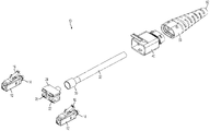
- FIG. 1 is a duplex fiber optic cable connector and a strain relief boot and crimp ring with a heat shrink tube.
- FIG. 2 is an assembly perspective view of a duplex fiber optic cable connector and the strain relief boot.
- FIG. 3 is a perspective view of a duplex fiber optic cable connector back post.
- FIG. 4 is a perspective view of a duplex fiber optic cable connector housing.
- FIG. 5 is a perspective view of a strain relief boot for a duplex fiber optic cable connector.
- the invention is directed to a connection system by which two fiber optic cable connectors are positioned together for connection to a duplex adapter.
- Embodiments of the invention include a single back post, housing and a strain relief boot by which the fiber optic connectors are positioned in proximity to one another.
- Embodiments of the invention can be used for connecting two LC style connectors side-by-side.
- Embodiments of the back post and housing of the invention can accommodate LC connectors that are available on the market without the need for substantial alterations to the LC connectors themselves.
- the invention can be used to connect two connectors other than LC connectors, such as SC connectors. Other embodiments of the invention are possible and envisioned.
- a duplex fiber optic cable connector apparatus 10 includes LC connectors 12 , a back post 20 , a crimp ring 30 , a shrink tube 32 , a housing 40 and a strain relief boot 60 .
- the LC connectors 12 are connected to be positioned side-by-side.
- the connectors 12 include a thumb latch 16 .
- the fiber optic connectors 12 may be any suitable type of connector (e.g., SC, LC, MT, ST, etc.).
- the back post 20 is configured to accept the connectors 12 .
- a first connector 12 is inserted into a first side 21 of the back post 20 and a second connector 12 is inserted into a second side 22 of the back post 20 .
- the crimp ring 30 connects the back post 30 to the shrink tube 32 .
- the shrink tube 32 is inserted through the housing 40 and the boot 60 .
- the shrink tube extends through the distal end 62 of the boot 60 .
- the back post 20 When assembled, as shown in FIG. 1 , the back post 20 is positioned inside the housing 40 .
- the connectors 12 extend outside of the housing 40 on an end opposite the position of the boot 60 .
- the apparatus 10 may be fabricated from any suitable material.
- the portions of the apparatus 10 such as the back post 20 and the housing 40 , are fabricated from plastic (e.g., a thermoplastic).
- the back post 20 includes an arcuate receptacle 26 on each of the sides 21 and 22 .
- the back post 20 is substantially rectangular and is configured to receive the first LC connector 12 in a first arcuate opening 26 on the first side 21 , and the second LC connector 12 in a second arcuate opening 26 on the second side 22 .
- the connectors 12 are positioned to rest in the receptacle 26 such that the connectors 12 are substantially parallel to one another and contained within the back post 20 (i.e., such that the connectors 12 do not substantially extend outside of the sides 21 , 22 of the back post 20 ).
- the connectors 12 are secured in the arcuate receptacles 26 .
- the back post 20 secures the LC connectors 12 in a duplex configuration such that the LC connectors 12 are connected into LC duplex adapters.
- the LC duplex adapters are industry standard adapters.
- the back post 20 includes a lip 28 configured above the top flat of the connector body. The lip 28 is configured to substantially prevent the connectors 12 from rotating before positioning in the connection system.
- the back post 20 includes a cylindrical connection port 24 .
- the port 24 is configured to connect to the crimp ring 30 .
- the port 24 forms a male connection with the crimp ring 30 and allows for passage of a fiber optic cable into the back post 20 for connection to the connectors 12 .
- the crimp ring 30 is connected to the shrink tube 32 .
- the shrink tube 32 is configured to provide a conduit, or passageway, through which the fiber optic cable passes to the connectors 12 for connection.
- a fiber optic cable is fastened to the back post 20 , for example, using the crimp ring 30 , although other fasteners are possible and envisioned.
- the housing 40 comprises a first end 41 into which the back post 20 is inserted, and a second end 43 that connects to the boot 60 .
- the housing 40 includes a body 44 having an opening 42 , a duplex thumb latch 50 , and a boot connector 46 having hooks 48 .
- the thumb latch 50 is positioned on the housing 40 such that individual thumb latches 16 for each of the respective LC connectors 12 are triggered by a single thumb latch 50 on the housing 40 .
- the duplex thumb latch 50 is configured to depress the thumb latch 16 of the first LC connector 12 and the thumb latch 16 of the second LC connector 12 , preferably at substantially the same time.
- the thumb latch 50 is configured to improve the efficiency in connection between the duplex LC connectors 12 and adapters (not shown).
- the LC connectors 12 and back post 20 are secured into the housing 40 .
- the back post 20 is substantially encapsulated within the housing 40 .
- the strain relief boot 60 is affixed to the housing 40 on an end opposite to the position of the back post 20 .
- the strain relief boot 60 is configured to reduce strain upon the cable inserted into the LC connectors 12 .
- the strain relief boot 60 includes a tapered body 61 .
- the body 61 includes slots 66 and snap holes 64 .
- the snap holes 64 are configured to accept the hooks 48 of the housing 40 such that the housing is secured into position with the boot 60 .
- the slots 66 are positioned along the length of the body 61 and provide flexibility to the boot 60 .
- the connection system of the duplex connector apparatus 10 operates to couple a fiber optic cable LC connector 12 with a second fiber optic cable LC connector 12 using the single housing 40 , the back post 20 and the strain relief boot 60 .
- standard fiber optic connectors 12 such as LC connectors 12 are secured together side-by-side in a duplex configuration.
- the back post 20 and the housing 40 are configured to secure the connectors 12 in position for efficient connection to an adapter.
- the boot 60 is configured to secure the fiber optic cables in position such that the cables are not kinked or crimped.
- the apparatus 10 is configured to improve the ease with which the connectors 12 are connected to an adapter.
- the apparatus 10 is configured to allow for the reduction of two fiber optic cables to a single cable method.
- the single cable method used in the apparatus 10 is configured to increase the efficiency in assembling the connector by reducing the parts required for the connection system.
- the back post 20 and the housing 40 can be comprised of an integrated part.
- the heat shrink tube 32 and the boot 60 can be comprised of an integrated part.
Abstract
An apparatus for holding a first fiber optic connector and a second fiber optic connector includes a housing configured to secure the first fiber optic connector and the second fiber optic connector at a first end and a strain relief boot connected to a second end of the housing. The housing and the strain relief boot are configured to form a passageway to receive a fiber optic cable that is connected to both the first fiber optic connector and the second fiber optic connector.
Description
This application claims the benefit of priority to U.S. Provisional Application No. 60/894,976, filed Mar. 15, 2007 and entitled, “Single Boot for Duplex Fiber Optic Connectors,” which is herein incorporated by reference in its entirety.
This application discloses an invention that is related, generally and in various embodiments, to an apparatus for use with a fiber optic retaining system. Fiber optic cable systems provide a large bandwidth capacity for the transmission of voice and data. In order to extend such systems closer and closer to the premises of the end subscribers, more and more fiber optic connections are required, which often necessitates duplex cable connectors. Such connections are typically made by highly skilled field personnel utilizing specialized tools and equipment.
A conventional way of pairing two connectors to accommodate increased transmission capacity requires many parts, and can make connection to an adapter a difficult task. Often, the connectors can rotate before connection to the adapters, which can cause damage to the hardware. Further, generally, a duplex LC connector includes two cables: one attached to each of the connectors, and these two connectors are held together by a clip. Multiple cables require multiple crimp rings, multiple heat shrink tubes, and multiple boots to attach. This can create a need for more space in order to secure attachment to fiber optic adapters.
In general, in an aspect, the invention is directed to an apparatus for holding a first fiber optic connector and a second fiber optic connector. The apparatus includes a housing configured to secure a first fiber optic connector and a second fiber optic connector at a first end and a strain relief boot connected to a second end of the housing, wherein the housing and the strain relief boot are configured to form a passageway to receive a fiber optic cable that is connected to the first fiber optic connector and the second fiber optic connector.
Aspects of the invention may include one or more of the following features. The apparatus can include a back post configured to secure the first fiber optic connector and the second fiber optic connector in a substantially fixed position. The back post can be configured to reside inside the housing. The housing and the back post can be integrally formed. The back post can include a first arcuate chamber to hold the first fiber optic connector and a second arcuate chamber to hold the second fiber optic connector. The apparatus can include a heat shrink tube configured to contain the fiber optic cable in the passageway. The apparatus can include a crimp ring configured to connect the heat shrink tube to the housing. The housing can include a thumb latch configured to release the first fiber optic connector and the second fiber optic connector.
In general, in another aspect, the invention is directed to a duplex fiber optic connector comprising a first fiber optic cable connector, a second fiber optic cable connector, a back post configured to secure the first fiber optic cable connector and the second fiber optic cable connector in a position adjacent one another, and a strain relief boot in connection with the back post and configured to receive a fiber optic cable that connects with the first and second fiber optic cable connectors.
Aspects of the invention may include one or more of the following features. The connector can include a housing configured to encapsulate the back post and connect with the strain relief boot. The connector can include a heat shrink tube configured to create a conduit within the strain relief boot to hold the fiber optic cable. The heat shrink tube can be connected to the back post via a crimp ring. The back post can include a first arcuate chamber to secure the first fiber optic connector and a second arcuate chamber to secure the second fiber optic connector.
The invention is directed to a connection system by which two fiber optic cable connectors are positioned together for connection to a duplex adapter. The invention includes a single back post, housing and a strain relief boot by which the fiber optic connectors are securely positioned in proximity to one another. The invention may exhibit one or more of the following capabilities. The housing and back post can improve the ease with which a duplex LC connector is received by a duplex LC adapter. For example, the back post can prevent rotation of the duplex LC connector before the connector is connected to the adapter. The invention can decrease the amount of space required for a duplex LC connector or other duplex connectors in order to achieve connection to an adapter.
It is to be understood that at least some of the figures and descriptions of the invention have been simplified to focus on elements that are relevant for a clear understanding of the invention, while eliminating, for purposes of clarity, other elements that those of ordinary skill in the art will appreciate may also comprise a portion of the invention. However, because such elements are well known in the art, and because they do not necessarily facilitate a better understanding of the invention, a description of such elements is not provided herein.
The invention is directed to a connection system by which two fiber optic cable connectors are positioned together for connection to a duplex adapter. Embodiments of the invention include a single back post, housing and a strain relief boot by which the fiber optic connectors are positioned in proximity to one another. Embodiments of the invention can be used for connecting two LC style connectors side-by-side. Embodiments of the back post and housing of the invention can accommodate LC connectors that are available on the market without the need for substantial alterations to the LC connectors themselves. The invention can be used to connect two connectors other than LC connectors, such as SC connectors. Other embodiments of the invention are possible and envisioned.
Referring to FIG. 1 and FIG. 2 , a duplex fiber optic cable connector apparatus 10 includes LC connectors 12, a back post 20, a crimp ring 30, a shrink tube 32, a housing 40 and a strain relief boot 60. The LC connectors 12 are connected to be positioned side-by-side. The connectors 12 include a thumb latch 16. The fiber optic connectors 12 may be any suitable type of connector (e.g., SC, LC, MT, ST, etc.). The back post 20 is configured to accept the connectors 12. A first connector 12 is inserted into a first side 21 of the back post 20 and a second connector 12 is inserted into a second side 22 of the back post 20. The crimp ring 30 connects the back post 30 to the shrink tube 32. The shrink tube 32 is inserted through the housing 40 and the boot 60. The shrink tube extends through the distal end 62 of the boot 60. When assembled, as shown in FIG. 1 , the back post 20 is positioned inside the housing 40. The connectors 12 extend outside of the housing 40 on an end opposite the position of the boot 60. The apparatus 10 may be fabricated from any suitable material. For example, according to various embodiments, the portions of the apparatus 10, such as the back post 20 and the housing 40, are fabricated from plastic (e.g., a thermoplastic).
Referring also to FIG. 3 , the back post 20 includes an arcuate receptacle 26 on each of the sides 21 and 22. The back post 20 is substantially rectangular and is configured to receive the first LC connector 12 in a first arcuate opening 26 on the first side 21, and the second LC connector 12 in a second arcuate opening 26 on the second side 22. The connectors 12 are positioned to rest in the receptacle 26 such that the connectors 12 are substantially parallel to one another and contained within the back post 20 (i.e., such that the connectors 12 do not substantially extend outside of the sides 21, 22 of the back post 20). The connectors 12 are secured in the arcuate receptacles 26. The back post 20 secures the LC connectors 12 in a duplex configuration such that the LC connectors 12 are connected into LC duplex adapters. Preferably, the LC duplex adapters are industry standard adapters. The back post 20 includes a lip 28 configured above the top flat of the connector body. The lip 28 is configured to substantially prevent the connectors 12 from rotating before positioning in the connection system.
The back post 20 includes a cylindrical connection port 24. The port 24 is configured to connect to the crimp ring 30. For example, the port 24 forms a male connection with the crimp ring 30 and allows for passage of a fiber optic cable into the back post 20 for connection to the connectors 12. The crimp ring 30 is connected to the shrink tube 32. The shrink tube 32 is configured to provide a conduit, or passageway, through which the fiber optic cable passes to the connectors 12 for connection. A fiber optic cable is fastened to the back post 20, for example, using the crimp ring 30, although other fasteners are possible and envisioned.
Referring also to FIG. 4 , the housing 40 comprises a first end 41 into which the back post 20 is inserted, and a second end 43 that connects to the boot 60. The housing 40 includes a body 44 having an opening 42, a duplex thumb latch 50, and a boot connector 46 having hooks 48. The thumb latch 50 is positioned on the housing 40 such that individual thumb latches 16 for each of the respective LC connectors 12 are triggered by a single thumb latch 50 on the housing 40. The duplex thumb latch 50 is configured to depress the thumb latch 16 of the first LC connector 12 and the thumb latch 16 of the second LC connector 12, preferably at substantially the same time. The thumb latch 50 is configured to improve the efficiency in connection between the duplex LC connectors 12 and adapters (not shown). The LC connectors 12 and back post 20 are secured into the housing 40. The back post 20 is substantially encapsulated within the housing 40.
Referring also to FIG. 5 , the strain relief boot 60 is affixed to the housing 40 on an end opposite to the position of the back post 20. The strain relief boot 60 is configured to reduce strain upon the cable inserted into the LC connectors 12. The strain relief boot 60 includes a tapered body 61. The body 61 includes slots 66 and snap holes 64. The snap holes 64 are configured to accept the hooks 48 of the housing 40 such that the housing is secured into position with the boot 60. The slots 66 are positioned along the length of the body 61 and provide flexibility to the boot 60.
The connection system of the duplex connector apparatus 10 operates to couple a fiber optic cable LC connector 12 with a second fiber optic cable LC connector 12 using the single housing 40, the back post 20 and the strain relief boot 60. In general, standard fiber optic connectors 12, such as LC connectors 12 are secured together side-by-side in a duplex configuration. The back post 20 and the housing 40 are configured to secure the connectors 12 in position for efficient connection to an adapter. The boot 60 is configured to secure the fiber optic cables in position such that the cables are not kinked or crimped. The apparatus 10 is configured to improve the ease with which the connectors 12 are connected to an adapter. The apparatus 10 is configured to allow for the reduction of two fiber optic cables to a single cable method. The single cable method used in the apparatus 10 is configured to increase the efficiency in assembling the connector by reducing the parts required for the connection system. The back post 20 and the housing 40 can be comprised of an integrated part. The heat shrink tube 32 and the boot 60 can be comprised of an integrated part.
The foregoing is considered as illustrative only of the principles of the invention. Further, since numerous modifications and changes will readily occur to those skilled in the art, it is not desired to limit the invention to the exact construction and operation shown and described, and accordingly, all suitable modifications and equivalents may be resorted to, falling within the scope of the invention.
Claims (20)
1. An apparatus for securing a first fiber optic connector and a second fiber optic connector, comprising:
a back post, having a first chamber for receiving a first fiber optic connector, and a second chamber for receiving a second fiber optic connector, said first and second chambers adapted and arranged to receive and hold said first and said second fiber optic connectors, respectively;
said back post further providing structure for preventing unwanted rotation of said first and second fiber optic connectors within said first and second chambers of the back post;
a housing that houses at least a portion of said back post and providing a conduit for a fiber optic cable through said housing, said housing further comprising a thumb latch arranged and configured to activate a latch in each of said first and second fiber optic connectors substantially at the same time.
2. The apparatus of claim 1 , further comprising a strain relief boot, coupled to said housing, and though which a fiber optic cable may be passed.
3. The apparatus of claim 1 , said first and second chambers comprising first and second arcuate chambers sized and shaped to mechanically mate to a pair of corresponding fiber optic connectors of the type available on the market, without modification to said connectors.
4. The apparatus of claim 3 , said first and second chambers comprising first and second arcuate chambers sized and shaped to mechanically mate to a pair of corresponding standard LC fiber optic connectors.
5. The apparatus of claim 3 , said first and second chambers comprising first and second arcuate chambers sized and shaped to mechanically mate to a pair of corresponding standard SC fiber optic connectors.
6. The apparatus of claim 1 , further comprising a heat shrinkable sleeve coupled to said housing to securely hold a fiber optic cable passing through said sleeve.
7. The apparatus of claim 6 , said housing comprising a cylindrical connection port for coupling said housing to said heat shrinkable sleeve.
8. The apparatus of claim 1 , said housing and said back post being integrally formed with one another as a unitary component of said apparatus.
9. An apparatus for securing a first fiber optic connector and a second fiber optic connector, comprising:
a back post and housing, integrally formed with one another, to provide a conduit through said housing for passage of a fiber optic cable through said housing and into said back post;
said back post being configured and arranged to receive and securely couple to a pair of fiber optic connectors of a type available in the market without modification to said connectors;
said back post comprising a first end through which said pair of connectors protrude; and
said housing comprising a second end through which a fiber optic cable can be received for coupling to said pair of fiber optic connectors in a duplex configuration,
wherein said housing further comprising a thumb latch configured to activate a latch in each of said first and second fiber optic connectors substantially at the same time.
10. The apparatus of claim 9 , further comprising a strain relief boot, coupled to said housing, and through which a fiber optic cable may be passed.
11. The apparatus of claim 9 , said housing comprising first and second chambers sized and shaped to mechanically mate to a pair of corresponding fiber optic connectors of the type available on the market, without modification to said connectors.
12. The apparatus of claim 11 , said first and second chambers comprising first and second arcuate chambers sized and shaped to mechanically mate to a pair of corresponding standard LC fiber optic connectors.
13. The apparatus of claim 11 , said first and second chambers comprising first and second arcuate chambers sized and shaped to mechanically mate to a pair of corresponding standard SC fiber optic connectors.
14. The apparatus of claim 11 , said back post comprising structure for preventing unwanted rotation of fiber optic connectors with respect to said first and second chambers.
15. The apparatus of claim 14 , said structure for preventing unwanted rotation comprising a flattened portion proximate to said chambers, which mechanically prevents rotation of said connectors once inserted into said chambers.
16. The apparatus of claim 11 , said chambers comprising a substantially rectangular cross section for receiving and securing fiber optic connectors having a corresponding substantially rectangular cross sectional body.
17. The apparatus of claim 9 , further comprising a heat shrinkable sleeve coupled to said housing to securely hold a fiber optic cable passing through said sleeve.
18. The apparatus of claim 17 , said housing comprising a cylindrical connection port for coupling said housing to said heat shrinkable sleeve.
19. The apparatus of claim 1 , said structure for preventing unwanted rotation of said connectors comprising a flattened portion proximate to said chambers, which mechanically prevents rotation of said connectors once inserted into said chambers.
20. The apparatus of claim 1 , said chambers comprising a substantially rectangular cross section for receiving and securing fiber optic connectors having a corresponding substantially rectangular cross sectional body.
Priority Applications (1)
| Application Number | Priority Date | Filing Date | Title |
|---|---|---|---|
| US12/048,740 US7641398B2 (en) | 2007-03-15 | 2008-03-14 | Single boot for duplex fiber optic connectors |
Applications Claiming Priority (2)
| Application Number | Priority Date | Filing Date | Title |
|---|---|---|---|
| US89497607P | 2007-03-15 | 2007-03-15 | |
| US12/048,740 US7641398B2 (en) | 2007-03-15 | 2008-03-14 | Single boot for duplex fiber optic connectors |
Publications (2)
| Publication Number | Publication Date |
|---|---|
| US20080226237A1 US20080226237A1 (en) | 2008-09-18 |
| US7641398B2 true US7641398B2 (en) | 2010-01-05 |
Family
ID=39671800
Family Applications (1)
| Application Number | Title | Priority Date | Filing Date |
|---|---|---|---|
| US12/048,740 Expired - Fee Related US7641398B2 (en) | 2007-03-15 | 2008-03-14 | Single boot for duplex fiber optic connectors |
Country Status (2)
| Country | Link |
|---|---|
| US (1) | US7641398B2 (en) |
| WO (1) | WO2008112986A1 (en) |
Cited By (118)
| Publication number | Priority date | Publication date | Assignee | Title |
|---|---|---|---|---|
| US20100220967A1 (en) * | 2009-02-27 | 2010-09-02 | Cooke Terry L | Hinged Fiber Optic Module Housing and Module |
| US20100322561A1 (en) * | 2009-06-18 | 2010-12-23 | Protai Photonic Co. Ltd. | Optical fiber connector and adapter |
| US20110081113A1 (en) * | 2009-10-02 | 2011-04-07 | Jones Ashley W | Fiber Optic Connector Assembly and Methods Therefor |
| WO2012058185A1 (en) * | 2010-10-29 | 2012-05-03 | Corning Cable Systems Llc | Fiber optic connector employing optical fiber guide member |
| US8465317B2 (en) | 2011-10-05 | 2013-06-18 | Senko Advanced Components, Inc. | Latching connector with remote release |
| US8538226B2 (en) | 2009-05-21 | 2013-09-17 | Corning Cable Systems Llc | Fiber optic equipment guides and rails configured with stopping position(s), and related equipment and methods |
| US8542973B2 (en) | 2010-04-23 | 2013-09-24 | Ccs Technology, Inc. | Fiber optic distribution device |
| US8593828B2 (en) | 2010-02-04 | 2013-11-26 | Corning Cable Systems Llc | Communications equipment housings, assemblies, and related alignment features and methods |
| US8622481B2 (en) | 2011-01-25 | 2014-01-07 | Joy Mm Delaware, Inc. | Fiber optic cable protection in a mining system |
| US8625950B2 (en) | 2009-12-18 | 2014-01-07 | Corning Cable Systems Llc | Rotary locking apparatus for fiber optic equipment trays and related methods |
| US8660397B2 (en) | 2010-04-30 | 2014-02-25 | Corning Cable Systems Llc | Multi-layer module |
| US8699838B2 (en) | 2009-05-14 | 2014-04-15 | Ccs Technology, Inc. | Fiber optic furcation module |
| US8705926B2 (en) | 2010-04-30 | 2014-04-22 | Corning Optical Communications LLC | Fiber optic housings having a removable top, and related components and methods |
| US8712206B2 (en) | 2009-06-19 | 2014-04-29 | Corning Cable Systems Llc | High-density fiber optic modules and module housings and related equipment |
| US8718436B2 (en) | 2010-08-30 | 2014-05-06 | Corning Cable Systems Llc | Methods, apparatuses for providing secure fiber optic connections |
| US8753022B2 (en) | 2010-11-30 | 2014-06-17 | Adc Telecommunications, Inc. | LC connector and method of assembly |
| US8764308B2 (en) | 2011-06-06 | 2014-07-01 | Panduit Corp. | Duplex clip assembly for fiber optic connectors |
| US20140226937A1 (en) * | 2009-09-28 | 2014-08-14 | Tyco Electronics Nederland Bv | Sealing enclosure for a connector on a cable such as a standardized fiber-optic connector |
| US8879881B2 (en) | 2010-04-30 | 2014-11-04 | Corning Cable Systems Llc | Rotatable routing guide and assembly |
| US8913866B2 (en) | 2010-03-26 | 2014-12-16 | Corning Cable Systems Llc | Movable adapter panel |
| US8953924B2 (en) | 2011-09-02 | 2015-02-10 | Corning Cable Systems Llc | Removable strain relief brackets for securing fiber optic cables and/or optical fibers to fiber optic equipment, and related assemblies and methods |
| US8965168B2 (en) | 2010-04-30 | 2015-02-24 | Corning Cable Systems Llc | Fiber management devices for fiber optic housings, and related components and methods |
| US8974124B2 (en) | 2012-08-16 | 2015-03-10 | Senko Advanced Components, Inc. | Fiber optic connector |
| US8989547B2 (en) | 2011-06-30 | 2015-03-24 | Corning Cable Systems Llc | Fiber optic equipment assemblies employing non-U-width-sized housings and related methods |
| US8985862B2 (en) | 2013-02-28 | 2015-03-24 | Corning Cable Systems Llc | High-density multi-fiber adapter housings |
| US8995812B2 (en) | 2012-10-26 | 2015-03-31 | Ccs Technology, Inc. | Fiber optic management unit and fiber optic distribution device |
| US9008485B2 (en) | 2011-05-09 | 2015-04-14 | Corning Cable Systems Llc | Attachment mechanisms employed to attach a rear housing section to a fiber optic housing, and related assemblies and methods |
| US9020320B2 (en) | 2008-08-29 | 2015-04-28 | Corning Cable Systems Llc | High density and bandwidth fiber optic apparatuses and related equipment and methods |
| US9022814B2 (en) | 2010-04-16 | 2015-05-05 | Ccs Technology, Inc. | Sealing and strain relief device for data cables |
| US9038832B2 (en) | 2011-11-30 | 2015-05-26 | Corning Cable Systems Llc | Adapter panel support assembly |
| US9042702B2 (en) | 2012-09-18 | 2015-05-26 | Corning Cable Systems Llc | Platforms and systems for fiber optic cable attachment |
| US9059578B2 (en) | 2009-02-24 | 2015-06-16 | Ccs Technology, Inc. | Holding device for a cable or an assembly for use with a cable |
| US9075217B2 (en) | 2010-04-30 | 2015-07-07 | Corning Cable Systems Llc | Apparatuses and related components and methods for expanding capacity of fiber optic housings |
| US9116324B2 (en) | 2010-10-29 | 2015-08-25 | Corning Cable Systems Llc | Stacked fiber optic modules and fiber optic equipment configured to support stacked fiber optic modules |
| US9146362B2 (en) | 2012-09-21 | 2015-09-29 | Adc Telecommunications, Inc. | Insertion and removal tool for a fiber optic ferrule alignment sleeve |
| US9188747B2 (en) | 2011-05-23 | 2015-11-17 | Senko Advanced Components, Inc. | True one piece housing fiber optic adapter |
| US9213161B2 (en) | 2010-11-05 | 2015-12-15 | Corning Cable Systems Llc | Fiber body holder and strain relief device |
| US9250409B2 (en) | 2012-07-02 | 2016-02-02 | Corning Cable Systems Llc | Fiber-optic-module trays and drawers for fiber-optic equipment |
| US9268103B2 (en) | 2013-05-10 | 2016-02-23 | Senko Advanced Components, Inc. | Interlockable fiber optic connector adaptors |
| US9274287B2 (en) | 2014-05-13 | 2016-03-01 | Senko Advanced Components, Inc. | Optical fiber connector and ferrule |
| US9279951B2 (en) | 2010-10-27 | 2016-03-08 | Corning Cable Systems Llc | Fiber optic module for limited space applications having a partially sealed module sub-assembly |
| US9297976B2 (en) | 2012-11-14 | 2016-03-29 | Clearfield, Inc. | Optical fiber connector |
| US9297964B2 (en) | 2014-04-18 | 2016-03-29 | Senko Advanced Components, Inc. | Optical fiber connector assembly |
| US9312676B2 (en) | 2010-01-29 | 2016-04-12 | Commscope Connectivity Belgium | Cable sealing and retaining device |
| US9310572B2 (en) | 2012-10-18 | 2016-04-12 | Corning Cable Systems Llc | Cable bend relief for fiber optic sub-assemblies and methods of assembling |
| US9360649B2 (en) | 2013-05-22 | 2016-06-07 | Senko Advanced Components, Inc. | Cable guide for fiber optic cables |
| US9448370B2 (en) | 2012-02-20 | 2016-09-20 | Commscope Technologies Llc | Connector and connector assembly |
| US9477049B2 (en) | 2013-12-20 | 2016-10-25 | Senko Advanced Components, Inc. | Lockable connectors and connection assemblies |
| US9494745B2 (en) | 2015-01-16 | 2016-11-15 | Senko Advanced Components, Inc. | Sealable communication cable connection assemblies |
| US9519118B2 (en) | 2010-04-30 | 2016-12-13 | Corning Optical Communications LLC | Removable fiber management sections for fiber optic housings, and related components and methods |
| US9535230B2 (en) | 2014-01-31 | 2017-01-03 | Senko Advanced Components, Inc. | Integrated fiber optic cable fan-out connector |
| US9599778B2 (en) | 2014-10-22 | 2017-03-21 | Senko Advanced Components, Inc. | Latching connector with remote release |
| US9618702B2 (en) | 2014-06-09 | 2017-04-11 | Senko Advanced Components, Inc. | Reduced-profile data transmission element connectors, adapters, and connection assemblies thereof |
| US9618703B2 (en) | 2013-10-03 | 2017-04-11 | Senko Advanced Components, Inc. | Connector housing for securing an optical cable and methods of use and manufacture thereof |
| US9632270B2 (en) | 2010-04-30 | 2017-04-25 | Corning Optical Communications LLC | Fiber optic housings configured for tool-less assembly, and related components and methods |
| US9645317B2 (en) | 2011-02-02 | 2017-05-09 | Corning Optical Communications LLC | Optical backplane extension modules, and related assemblies suitable for establishing optical connections to information processing modules disposed in equipment racks |
| US9658409B2 (en) | 2015-03-03 | 2017-05-23 | Senko Advanced Components, Inc. | Optical fiber connector with changeable polarity |
| US9684130B2 (en) | 2011-05-04 | 2017-06-20 | The Siemon Company | Fiber optic connector with polarity change |
| US9720195B2 (en) | 2010-04-30 | 2017-08-01 | Corning Optical Communications LLC | Apparatuses and related components and methods for attachment and release of fiber optic housings to and from an equipment rack |
| US9761998B2 (en) | 2011-02-08 | 2017-09-12 | Commscope Technologies Llc | Release tab for an electrical connector and electrical connector comprising said release tab |
| US9825403B2 (en) | 2011-02-08 | 2017-11-21 | Commscope Technologies Llc | RJ type connector including a disengagement feature acting on the latch of the connector |
| US10067301B2 (en) | 2014-01-13 | 2018-09-04 | Commscope Connectivity Uk Limited | Fiber optic connector |
| US10094996B2 (en) | 2008-08-29 | 2018-10-09 | Corning Optical Communications, Llc | Independently translatable modules and fiber optic equipment trays in fiber optic equipment |
| US10146016B1 (en) | 2017-05-10 | 2018-12-04 | Senko Advanced Components, Inc | MPO micro-latchlock connector |
| US10185100B2 (en) | 2017-01-30 | 2019-01-22 | Senko Advanced Components, Inc | Modular connector and adapter assembly using a removable anchor device |
| US10191230B2 (en) | 2017-01-30 | 2019-01-29 | Senko Advanced Components, Inc. | Optical connectors with reversible polarity |
| US10209461B2 (en) | 2017-04-07 | 2019-02-19 | Senko Advanced Components | Behind the wall optical connector with reduced components |
| US10228521B2 (en) | 2016-12-05 | 2019-03-12 | Senko Advanced Components, Inc. | Narrow width adapters and connectors with modular latching arm |
| US10281668B2 (en) * | 2017-07-14 | 2019-05-07 | Senko Advanced Components, Inc. | Ultra-small form factor optical connectors |
| US10295759B2 (en) | 2017-05-18 | 2019-05-21 | Senko Advanced Components, Inc. | Optical connector with forward-biasing projections |
| US10302874B2 (en) | 2015-05-15 | 2019-05-28 | Commscope Telecommunications (Shanghai) Co., Ltd. | Alignment sleeve assembly and fiber optic adapter |
| US10359576B2 (en) | 2017-06-15 | 2019-07-23 | Senko Advanced Components, Inc. | SC low profile connector with optional boot |
| US10359583B2 (en) | 2017-04-07 | 2019-07-23 | Senko Advanced Components, Inc. | Behind the wall optical connector with reduced components |
| US10401576B2 (en) | 2017-05-10 | 2019-09-03 | Senko Advanced Components, Inc. | MPO micro-latch-lock connector |
| US10416394B2 (en) | 2017-01-30 | 2019-09-17 | Senko Advanced Components, Inc. | Fiber optic receptacle with integrated device therein |
| US10444442B2 (en) | 2017-11-03 | 2019-10-15 | Senko Advanced Components, Inc. | MPO optical fiber connector |
| US10444441B1 (en) | 2018-08-10 | 2019-10-15 | Senko Advanced Components, Inc. | Pivotable housing for a fiber optic connector |
| US10444444B2 (en) | 2017-01-30 | 2019-10-15 | Senko Advanced Components, Inc. | Remote release tab connector assembly |
| US10578813B2 (en) | 2017-03-20 | 2020-03-03 | Senko Advanced Components, Inc. | MPO connector assembly with push-pull tab |
| US10613278B2 (en) | 2010-01-29 | 2020-04-07 | CommScope Connectivity Belgium BVBA | Cable sealing device, cable termination and attaching device |
| US10641972B2 (en) | 2017-08-17 | 2020-05-05 | Senko Advanced Components, Inc | Anti-jam alignment sleeve holder or connector housing for a ferrule assembly |
| US10678000B2 (en) | 2018-01-05 | 2020-06-09 | Senko Advanced Components, Inc. | Pull rod and alignment key for a fiber optic connector and adapter |
| US10705300B2 (en) | 2017-07-14 | 2020-07-07 | Senko Advanced Components, Inc. | Small form factor fiber optic connector with multi-purpose boot assembly |
| US10718911B2 (en) | 2017-08-24 | 2020-07-21 | Senko Advanced Components, Inc. | Ultra-small form factor optical connectors using a push-pull boot receptacle release |
| US10718910B2 (en) | 2017-05-03 | 2020-07-21 | Senko Advanced Components, Inc | Field terminated ruggedized fiber optic connector system |
| US10725248B2 (en) | 2017-01-30 | 2020-07-28 | Senko Advanced Components, Inc. | Fiber optic receptacle with integrated device therein incorporating a behind-the-wall fiber optic receptacle |
| US10754098B2 (en) | 2017-04-07 | 2020-08-25 | Senko Advanced Components, Inc. | Behind the wall optical connector with reduced components |
| US10866371B2 (en) | 2016-06-28 | 2020-12-15 | Senko Advanced Components, Inc. | Adapter system for multi-fiber mechanical transfer type ferrule |
| US10921530B2 (en) | 2018-09-12 | 2021-02-16 | Senko Advanced Components, Inc. | LC type connector with push/pull assembly for releasing connector from a receptacle using a cable boot |
| US10921528B2 (en) | 2018-06-07 | 2021-02-16 | Senko Advanced Components, Inc. | Dual spring multi-fiber optic connector |
| US10921531B2 (en) | 2018-09-12 | 2021-02-16 | Senko Advanced Components, Inc. | LC type connector with push/pull assembly for releasing connector from a receptacle using a cable boot |
| US10989884B2 (en) | 2017-04-07 | 2021-04-27 | Senko Advanced Components, Inc. | Behind the wall optical connector with reduced components |
| US11002923B2 (en) | 2017-11-21 | 2021-05-11 | Senko Advanced Components, Inc. | Fiber optic connector with cable boot release having a two-piece clip assembly |
| US11041993B2 (en) | 2018-04-19 | 2021-06-22 | Senko Advanced Components, Inc. | Fiber optic adapter with removable insert for polarity change and removal tool for the same |
| US11073662B2 (en) | 2015-05-29 | 2021-07-27 | Senko Advanced Components, Inc. | Optical fiber connector with changeable gender |
| US11073664B2 (en) | 2018-08-13 | 2021-07-27 | Senko Advanced Components, Inc. | Cable boot assembly for releasing fiber optic connector from a receptacle |
| US11086087B2 (en) | 2018-09-12 | 2021-08-10 | Senko Advanced Components, Inc. | LC type connector with clip-on push/pull tab for releasing connector from a receptacle using a cable boot |
| US11112566B2 (en) | 2018-03-19 | 2021-09-07 | Senko Advanced Components, Inc. | Removal tool for removing a plural of micro optical connectors from an adapter interface |
| US11175464B2 (en) | 2018-11-25 | 2021-11-16 | Senko Advanced Components, Inc. | Open ended spring body for use in an optical fiber connector |
| US11187857B2 (en) | 2018-07-15 | 2021-11-30 | Senko Advanced Components, Inc. | Ultra-small form factor optical connector and adapter |
| US11215767B2 (en) | 2017-06-07 | 2022-01-04 | Commscope Technologies Llc | Fiber optic adapter and cassette |
| US11294136B2 (en) | 2008-08-29 | 2022-04-05 | Corning Optical Communications LLC | High density and bandwidth fiber optic apparatuses and related equipment and methods |
| US11314024B2 (en) | 2019-06-13 | 2022-04-26 | Senko Advanced Components, Inc. | Lever actuated latch arm for releasing a fiber optic connector from a receptacle port and method of use |
| US11320606B2 (en) | 2017-01-30 | 2022-05-03 | Senko Advanced Components, Inc. | Optical connector |
| US11327240B2 (en) | 2017-09-15 | 2022-05-10 | Commscope Technologies Llc | Fiber optic connector with boot-integrated release and related assemblies |
| US11340406B2 (en) | 2019-04-19 | 2022-05-24 | Senko Advanced Components, Inc. | Small form factor fiber optic connector with resilient latching mechanism for securing within a hook-less receptacle |
| US11353664B1 (en) | 2019-08-21 | 2022-06-07 | Senko Advanced Components, Inc. | Fiber optic connector |
| US11448835B2 (en) | 2016-12-05 | 2022-09-20 | Senko Advanced Components, Inc. | Fiber optic connector with releasable pull/push tab with securing protrusions |
| US11467354B2 (en) | 2019-07-23 | 2022-10-11 | Senko Advanced Components, Inc. | Ultra-small form factor receptacle for receiving a fiber optic connector opposing a ferrule assembly |
| US11520111B2 (en) | 2019-11-13 | 2022-12-06 | Senko Advanced Components, Inc. | Fiber optic connector |
| US11531168B2 (en) | 2017-06-28 | 2022-12-20 | Corning Research & Development Corporation | Fiber optic connectors having a keying structure and methods of making the same |
| US11555966B2 (en) | 2017-11-17 | 2023-01-17 | Commscope Technologies Llc | Fiber optic connector locking feature |
| US11579379B2 (en) | 2019-03-28 | 2023-02-14 | Senko Advanced Components, Inc. | Fiber optic adapter assembly |
| US11689247B2 (en) | 2019-01-16 | 2023-06-27 | Mertek Industries, Llc | Patch cord including wireless components |
| US11686913B2 (en) | 2020-11-30 | 2023-06-27 | Corning Research & Development Corporation | Fiber optic cable assemblies and connector assemblies having a crimp ring and crimp body and methods of fabricating the same |
| US11806831B2 (en) | 2018-11-21 | 2023-11-07 | Senko Advanced Components, Inc. | Fixture and method for polishing fiber optic connector ferrules |
| US11822133B2 (en) | 2017-07-14 | 2023-11-21 | Senko Advanced Components, Inc. | Ultra-small form factor optical connector and adapter |
| US11934017B2 (en) | 2021-03-02 | 2024-03-19 | Corning Research & Development Corporation | Polarity changeable optical connector |
Families Citing this family (9)
| Publication number | Priority date | Publication date | Assignee | Title |
|---|---|---|---|---|
| US8152385B2 (en) * | 2009-02-27 | 2012-04-10 | Corning Cable Systems Llc | Duplex fiber optic assemblies suitable for polarity reversal and methods therefor |
| JP4995305B2 (en) * | 2010-06-04 | 2012-08-08 | サンコール株式会社 | 2-core optical connector unit |
| US8727638B2 (en) * | 2011-12-21 | 2014-05-20 | Alliance Fiber Optic Products Co., Ltd. | Fiber channel-inter changeable fiber optic connector |
| US9235010B2 (en) * | 2013-06-28 | 2016-01-12 | Commscope Technologies Llc | Robust optical crimp connector |
| US10712512B2 (en) * | 2017-11-21 | 2020-07-14 | Senko Advanced Components, Inc | Fiber optic connector assemblies with cable boot release |
| CN112823304B (en) * | 2018-09-12 | 2023-09-29 | 扇港元器件股份有限公司 | Fiber optic connector assembly with cable jacket release |
| CN113224567A (en) * | 2021-05-11 | 2021-08-06 | 锐捷网络股份有限公司 | Photoelectric connection device, cage and electronic equipment |
| US20230280541A1 (en) | 2022-03-02 | 2023-09-07 | Corning Research & Development Corporation | Polarity changeable optical connector |
| USD1008971S1 (en) * | 2023-05-22 | 2023-12-26 | Chundi Liu | Connector |
Citations (10)
| Publication number | Priority date | Publication date | Assignee | Title |
|---|---|---|---|---|
| EP1074868A1 (en) | 1999-08-05 | 2001-02-07 | Yazaki Corporation | Optical connector |
| WO2001079904A2 (en) | 2000-04-18 | 2001-10-25 | Krone Gmbh | Duplex connectors for optical fibre plug connectors |
| US6511230B1 (en) * | 2000-02-04 | 2003-01-28 | Panduit Corp. | Fiber optic connection system |
| US20040136657A1 (en) | 2003-01-15 | 2004-07-15 | Fci Americas Technology, Inc. | Guide boot for a fiber-optic cable |
| EP1566674A1 (en) | 2004-02-19 | 2005-08-24 | Reichle & De-Massari AG | Plug housing of an optical plug connector for industrial environment |
| US20060089049A1 (en) * | 2004-10-27 | 2006-04-27 | Panduit Corp. | Fiber optic industrial connector |
| US20060269194A1 (en) * | 2005-05-27 | 2006-11-30 | Luther James P | Fiber optic connector having keyed ferrule holder |
| DE202006011910U1 (en) | 2005-11-09 | 2007-03-22 | Weidmüller Interface GmbH & Co. KG | Adapter for receiving a plug part |
| DE102006019335A1 (en) | 2006-04-24 | 2007-10-25 | Telegärtner Gerätebau GmbH | Optical connector, has retaining part that is arranged at one end of carrier part for laterally holding and positioning optical connecting unit and is formed in length adjustable manner, where retaining part has U-profile like shape |
| US7325980B2 (en) * | 2005-08-26 | 2008-02-05 | Tyco Electronics Corporation | Duplex style fiber optic connector interface assembly |
-
2008
- 2008-03-14 US US12/048,740 patent/US7641398B2/en not_active Expired - Fee Related
- 2008-03-14 WO PCT/US2008/057023 patent/WO2008112986A1/en active Application Filing
Patent Citations (10)
| Publication number | Priority date | Publication date | Assignee | Title |
|---|---|---|---|---|
| EP1074868A1 (en) | 1999-08-05 | 2001-02-07 | Yazaki Corporation | Optical connector |
| US6511230B1 (en) * | 2000-02-04 | 2003-01-28 | Panduit Corp. | Fiber optic connection system |
| WO2001079904A2 (en) | 2000-04-18 | 2001-10-25 | Krone Gmbh | Duplex connectors for optical fibre plug connectors |
| US20040136657A1 (en) | 2003-01-15 | 2004-07-15 | Fci Americas Technology, Inc. | Guide boot for a fiber-optic cable |
| EP1566674A1 (en) | 2004-02-19 | 2005-08-24 | Reichle & De-Massari AG | Plug housing of an optical plug connector for industrial environment |
| US20060089049A1 (en) * | 2004-10-27 | 2006-04-27 | Panduit Corp. | Fiber optic industrial connector |
| US20060269194A1 (en) * | 2005-05-27 | 2006-11-30 | Luther James P | Fiber optic connector having keyed ferrule holder |
| US7325980B2 (en) * | 2005-08-26 | 2008-02-05 | Tyco Electronics Corporation | Duplex style fiber optic connector interface assembly |
| DE202006011910U1 (en) | 2005-11-09 | 2007-03-22 | Weidmüller Interface GmbH & Co. KG | Adapter for receiving a plug part |
| DE102006019335A1 (en) | 2006-04-24 | 2007-10-25 | Telegärtner Gerätebau GmbH | Optical connector, has retaining part that is arranged at one end of carrier part for laterally holding and positioning optical connecting unit and is formed in length adjustable manner, where retaining part has U-profile like shape |
Cited By (215)
| Publication number | Priority date | Publication date | Assignee | Title |
|---|---|---|---|---|
| US10459184B2 (en) | 2008-08-29 | 2019-10-29 | Corning Optical Communications LLC | High density and bandwidth fiber optic apparatuses and related equipment and methods |
| US11294136B2 (en) | 2008-08-29 | 2022-04-05 | Corning Optical Communications LLC | High density and bandwidth fiber optic apparatuses and related equipment and methods |
| US10094996B2 (en) | 2008-08-29 | 2018-10-09 | Corning Optical Communications, Llc | Independently translatable modules and fiber optic equipment trays in fiber optic equipment |
| US10120153B2 (en) | 2008-08-29 | 2018-11-06 | Corning Optical Communications, Llc | Independently translatable modules and fiber optic equipment trays in fiber optic equipment |
| US9020320B2 (en) | 2008-08-29 | 2015-04-28 | Corning Cable Systems Llc | High density and bandwidth fiber optic apparatuses and related equipment and methods |
| US10852499B2 (en) | 2008-08-29 | 2020-12-01 | Corning Optical Communications LLC | High density and bandwidth fiber optic apparatuses and related equipment and methods |
| US10126514B2 (en) | 2008-08-29 | 2018-11-13 | Corning Optical Communications, Llc | Independently translatable modules and fiber optic equipment trays in fiber optic equipment |
| US11754796B2 (en) | 2008-08-29 | 2023-09-12 | Corning Optical Communications LLC | Independently translatable modules and fiber optic equipment trays in fiber optic equipment |
| US10222570B2 (en) | 2008-08-29 | 2019-03-05 | Corning Optical Communications LLC | Independently translatable modules and fiber optic equipment trays in fiber optic equipment |
| US11086089B2 (en) | 2008-08-29 | 2021-08-10 | Corning Optical Communications LLC | High density and bandwidth fiber optic apparatuses and related equipment and methods |
| US11609396B2 (en) | 2008-08-29 | 2023-03-21 | Corning Optical Communications LLC | High density and bandwidth fiber optic apparatuses and related equipment and methods |
| US10564378B2 (en) | 2008-08-29 | 2020-02-18 | Corning Optical Communications LLC | High density and bandwidth fiber optic apparatuses and related equipment and methods |
| US11092767B2 (en) | 2008-08-29 | 2021-08-17 | Corning Optical Communications LLC | High density and bandwidth fiber optic apparatuses and related equipment and methods |
| US11294135B2 (en) | 2008-08-29 | 2022-04-05 | Corning Optical Communications LLC | High density and bandwidth fiber optic apparatuses and related equipment and methods |
| US10416405B2 (en) | 2008-08-29 | 2019-09-17 | Corning Optical Communications LLC | Independently translatable modules and fiber optic equipment trays in fiber optic equipment |
| US10422971B2 (en) | 2008-08-29 | 2019-09-24 | Corning Optical Communicatinos LLC | High density and bandwidth fiber optic apparatuses and related equipment and methods |
| US10444456B2 (en) | 2008-08-29 | 2019-10-15 | Corning Optical Communications LLC | High density and bandwidth fiber optic apparatuses and related equipment and methods |
| US9910236B2 (en) | 2008-08-29 | 2018-03-06 | Corning Optical Communications LLC | High density and bandwidth fiber optic apparatuses and related equipment and methods |
| US10606014B2 (en) | 2008-08-29 | 2020-03-31 | Corning Optical Communications LLC | Independently translatable modules and fiber optic equipment trays in fiber optic equipment |
| US9059578B2 (en) | 2009-02-24 | 2015-06-16 | Ccs Technology, Inc. | Holding device for a cable or an assembly for use with a cable |
| US20100220967A1 (en) * | 2009-02-27 | 2010-09-02 | Cooke Terry L | Hinged Fiber Optic Module Housing and Module |
| US8699838B2 (en) | 2009-05-14 | 2014-04-15 | Ccs Technology, Inc. | Fiber optic furcation module |
| US9075216B2 (en) | 2009-05-21 | 2015-07-07 | Corning Cable Systems Llc | Fiber optic housings configured to accommodate fiber optic modules/cassettes and fiber optic panels, and related components and methods |
| US8538226B2 (en) | 2009-05-21 | 2013-09-17 | Corning Cable Systems Llc | Fiber optic equipment guides and rails configured with stopping position(s), and related equipment and methods |
| US20100322561A1 (en) * | 2009-06-18 | 2010-12-23 | Protai Photonic Co. Ltd. | Optical fiber connector and adapter |
| US8408815B2 (en) | 2009-06-18 | 2013-04-02 | Senko Advanced Components, Inc. | Optical fiber connector and adapter |
| US8712206B2 (en) | 2009-06-19 | 2014-04-29 | Corning Cable Systems Llc | High-density fiber optic modules and module housings and related equipment |
| US11169334B2 (en) | 2009-09-28 | 2021-11-09 | Commscope Technologies Llc | Sealing enclosure for a connector on a cable such as a standardized fiber-optic connector |
| US11573380B2 (en) | 2009-09-28 | 2023-02-07 | Commscope Technologies Llc | Sealing enclosure for a connector on a cable such as a standardized fiber-optic connector having a compression seal |
| US9122021B2 (en) | 2009-09-28 | 2015-09-01 | Te Connectivity Nederland B.V. | Sealing enclosure for a connector on a cable, such as a standardized fiber-optic connector |
| US20140226937A1 (en) * | 2009-09-28 | 2014-08-14 | Tyco Electronics Nederland Bv | Sealing enclosure for a connector on a cable such as a standardized fiber-optic connector |
| US10754100B2 (en) * | 2009-09-28 | 2020-08-25 | Commscope Technologies Llc | Sealing enclosure for a connector on a cable such as a standardized fiber-optic connector |
| US10830960B2 (en) | 2009-09-28 | 2020-11-10 | Commscope Technologies Llc | Sealing enclosure for a connector on a cable such as a standardized fiber-optic connector |
| US20110081113A1 (en) * | 2009-10-02 | 2011-04-07 | Jones Ashley W | Fiber Optic Connector Assembly and Methods Therefor |
| US8625950B2 (en) | 2009-12-18 | 2014-01-07 | Corning Cable Systems Llc | Rotary locking apparatus for fiber optic equipment trays and related methods |
| US11550105B2 (en) | 2010-01-29 | 2023-01-10 | CommScope Connectivity Belgium BVBA | Fiber plug connector with seal and threaded region |
| US9312676B2 (en) | 2010-01-29 | 2016-04-12 | Commscope Connectivity Belgium | Cable sealing and retaining device |
| US10613278B2 (en) | 2010-01-29 | 2020-04-07 | CommScope Connectivity Belgium BVBA | Cable sealing device, cable termination and attaching device |
| US8992099B2 (en) | 2010-02-04 | 2015-03-31 | Corning Cable Systems Llc | Optical interface cards, assemblies, and related methods, suited for installation and use in antenna system equipment |
| US8593828B2 (en) | 2010-02-04 | 2013-11-26 | Corning Cable Systems Llc | Communications equipment housings, assemblies, and related alignment features and methods |
| US8913866B2 (en) | 2010-03-26 | 2014-12-16 | Corning Cable Systems Llc | Movable adapter panel |
| US9022814B2 (en) | 2010-04-16 | 2015-05-05 | Ccs Technology, Inc. | Sealing and strain relief device for data cables |
| US8542973B2 (en) | 2010-04-23 | 2013-09-24 | Ccs Technology, Inc. | Fiber optic distribution device |
| US9632270B2 (en) | 2010-04-30 | 2017-04-25 | Corning Optical Communications LLC | Fiber optic housings configured for tool-less assembly, and related components and methods |
| US8965168B2 (en) | 2010-04-30 | 2015-02-24 | Corning Cable Systems Llc | Fiber management devices for fiber optic housings, and related components and methods |
| US8879881B2 (en) | 2010-04-30 | 2014-11-04 | Corning Cable Systems Llc | Rotatable routing guide and assembly |
| US9720195B2 (en) | 2010-04-30 | 2017-08-01 | Corning Optical Communications LLC | Apparatuses and related components and methods for attachment and release of fiber optic housings to and from an equipment rack |
| US8705926B2 (en) | 2010-04-30 | 2014-04-22 | Corning Optical Communications LLC | Fiber optic housings having a removable top, and related components and methods |
| US9519118B2 (en) | 2010-04-30 | 2016-12-13 | Corning Optical Communications LLC | Removable fiber management sections for fiber optic housings, and related components and methods |
| US9075217B2 (en) | 2010-04-30 | 2015-07-07 | Corning Cable Systems Llc | Apparatuses and related components and methods for expanding capacity of fiber optic housings |
| US8660397B2 (en) | 2010-04-30 | 2014-02-25 | Corning Cable Systems Llc | Multi-layer module |
| US8718436B2 (en) | 2010-08-30 | 2014-05-06 | Corning Cable Systems Llc | Methods, apparatuses for providing secure fiber optic connections |
| US9279951B2 (en) | 2010-10-27 | 2016-03-08 | Corning Cable Systems Llc | Fiber optic module for limited space applications having a partially sealed module sub-assembly |
| US9116324B2 (en) | 2010-10-29 | 2015-08-25 | Corning Cable Systems Llc | Stacked fiber optic modules and fiber optic equipment configured to support stacked fiber optic modules |
| US8662760B2 (en) | 2010-10-29 | 2014-03-04 | Corning Cable Systems Llc | Fiber optic connector employing optical fiber guide member |
| WO2012058185A1 (en) * | 2010-10-29 | 2012-05-03 | Corning Cable Systems Llc | Fiber optic connector employing optical fiber guide member |
| US9213161B2 (en) | 2010-11-05 | 2015-12-15 | Corning Cable Systems Llc | Fiber body holder and strain relief device |
| US9223096B2 (en) | 2010-11-30 | 2015-12-29 | Commscope Technologies Llc | LC connector and method of assembly |
| US8753022B2 (en) | 2010-11-30 | 2014-06-17 | Adc Telecommunications, Inc. | LC connector and method of assembly |
| US8622481B2 (en) | 2011-01-25 | 2014-01-07 | Joy Mm Delaware, Inc. | Fiber optic cable protection in a mining system |
| US8950822B2 (en) | 2011-01-25 | 2015-02-10 | Joy Mm Delaware, Inc. | Fiber optic cable protection in a mining system |
| US9645317B2 (en) | 2011-02-02 | 2017-05-09 | Corning Optical Communications LLC | Optical backplane extension modules, and related assemblies suitable for establishing optical connections to information processing modules disposed in equipment racks |
| US10481335B2 (en) | 2011-02-02 | 2019-11-19 | Corning Optical Communications, Llc | Dense shuttered fiber optic connectors and assemblies suitable for establishing optical connections for optical backplanes in equipment racks |
| US11742617B2 (en) | 2011-02-08 | 2023-08-29 | Commscope Technologies Llc | RJ type connector including a disengagement feature acting on the latch of the connector |
| US9991635B2 (en) | 2011-02-08 | 2018-06-05 | Commscope Technologies Llc | Release tab for an electrical connector and electrical connector comprising said release tab |
| US11322889B2 (en) | 2011-02-08 | 2022-05-03 | Commscope Technologies Llc | RJ type connector including a disengagement feature acting on the latch of the connector |
| US9761998B2 (en) | 2011-02-08 | 2017-09-12 | Commscope Technologies Llc | Release tab for an electrical connector and electrical connector comprising said release tab |
| US9825403B2 (en) | 2011-02-08 | 2017-11-21 | Commscope Technologies Llc | RJ type connector including a disengagement feature acting on the latch of the connector |
| US9684130B2 (en) | 2011-05-04 | 2017-06-20 | The Siemon Company | Fiber optic connector with polarity change |
| US10228516B2 (en) | 2011-05-04 | 2019-03-12 | The Siemon Company | Fiber optic connector with polarity change |
| US9008485B2 (en) | 2011-05-09 | 2015-04-14 | Corning Cable Systems Llc | Attachment mechanisms employed to attach a rear housing section to a fiber optic housing, and related assemblies and methods |
| US9188747B2 (en) | 2011-05-23 | 2015-11-17 | Senko Advanced Components, Inc. | True one piece housing fiber optic adapter |
| US9063303B2 (en) | 2011-06-06 | 2015-06-23 | Panduit Corp. | Duplex clip assembly for fiber optic connectors |
| US9557496B2 (en) | 2011-06-06 | 2017-01-31 | Panduit Corp. | Duplex clip assembly for fiber optic connectors |
| US8764308B2 (en) | 2011-06-06 | 2014-07-01 | Panduit Corp. | Duplex clip assembly for fiber optic connectors |
| US9829650B2 (en) | 2011-06-06 | 2017-11-28 | Panduit Corp. | Duplex clip assembly for fiber optic connectors |
| US8989547B2 (en) | 2011-06-30 | 2015-03-24 | Corning Cable Systems Llc | Fiber optic equipment assemblies employing non-U-width-sized housings and related methods |
| US8953924B2 (en) | 2011-09-02 | 2015-02-10 | Corning Cable Systems Llc | Removable strain relief brackets for securing fiber optic cables and/or optical fibers to fiber optic equipment, and related assemblies and methods |
| USRE49942E1 (en) | 2011-10-05 | 2024-04-23 | Senko Advanced Components, Inc. | Latching connector with remote release |
| US8465317B2 (en) | 2011-10-05 | 2013-06-18 | Senko Advanced Components, Inc. | Latching connector with remote release |
| US9038832B2 (en) | 2011-11-30 | 2015-05-26 | Corning Cable Systems Llc | Adapter panel support assembly |
| US9448370B2 (en) | 2012-02-20 | 2016-09-20 | Commscope Technologies Llc | Connector and connector assembly |
| US9250409B2 (en) | 2012-07-02 | 2016-02-02 | Corning Cable Systems Llc | Fiber-optic-module trays and drawers for fiber-optic equipment |
| US8974124B2 (en) | 2012-08-16 | 2015-03-10 | Senko Advanced Components, Inc. | Fiber optic connector |
| US9042702B2 (en) | 2012-09-18 | 2015-05-26 | Corning Cable Systems Llc | Platforms and systems for fiber optic cable attachment |
| US9915793B2 (en) | 2012-09-21 | 2018-03-13 | Commscope Technologies Llc | Removal tool for a fiber optic ferrule alignment sleeve |
| US9146362B2 (en) | 2012-09-21 | 2015-09-29 | Adc Telecommunications, Inc. | Insertion and removal tool for a fiber optic ferrule alignment sleeve |
| US9310572B2 (en) | 2012-10-18 | 2016-04-12 | Corning Cable Systems Llc | Cable bend relief for fiber optic sub-assemblies and methods of assembling |
| US8995812B2 (en) | 2012-10-26 | 2015-03-31 | Ccs Technology, Inc. | Fiber optic management unit and fiber optic distribution device |
| US9297976B2 (en) | 2012-11-14 | 2016-03-29 | Clearfield, Inc. | Optical fiber connector |
| US8985862B2 (en) | 2013-02-28 | 2015-03-24 | Corning Cable Systems Llc | High-density multi-fiber adapter housings |
| US9268103B2 (en) | 2013-05-10 | 2016-02-23 | Senko Advanced Components, Inc. | Interlockable fiber optic connector adaptors |
| US9360649B2 (en) | 2013-05-22 | 2016-06-07 | Senko Advanced Components, Inc. | Cable guide for fiber optic cables |
| US9618703B2 (en) | 2013-10-03 | 2017-04-11 | Senko Advanced Components, Inc. | Connector housing for securing an optical cable and methods of use and manufacture thereof |
| US9477049B2 (en) | 2013-12-20 | 2016-10-25 | Senko Advanced Components, Inc. | Lockable connectors and connection assemblies |
| US11079556B2 (en) | 2014-01-13 | 2021-08-03 | Commscope Connectivity Uk Limited | Fiber optic connector |
| US10067301B2 (en) | 2014-01-13 | 2018-09-04 | Commscope Connectivity Uk Limited | Fiber optic connector |
| US10545296B2 (en) | 2014-01-13 | 2020-01-28 | Commscope Connectivity Uk Limited | Fiber optic connector |
| US11604319B2 (en) | 2014-01-13 | 2023-03-14 | Commscope Connectivity Uk Limited | Fiber optic connector |
| US9535230B2 (en) | 2014-01-31 | 2017-01-03 | Senko Advanced Components, Inc. | Integrated fiber optic cable fan-out connector |
| US11067759B2 (en) | 2014-01-31 | 2021-07-20 | Senko Advanced Components, Inc. | Ingress protected fan-out connector and adapter assembly |
| US9297964B2 (en) | 2014-04-18 | 2016-03-29 | Senko Advanced Components, Inc. | Optical fiber connector assembly |
| US9274287B2 (en) | 2014-05-13 | 2016-03-01 | Senko Advanced Components, Inc. | Optical fiber connector and ferrule |
| US11402587B2 (en) | 2014-06-09 | 2022-08-02 | Senko Advanced Components, Inc. | Reduced-profile data transmission element connectors, adapters, and connection assemblies thereof |
| US9618702B2 (en) | 2014-06-09 | 2017-04-11 | Senko Advanced Components, Inc. | Reduced-profile data transmission element connectors, adapters, and connection assemblies thereof |
| US10197740B2 (en) | 2014-06-09 | 2019-02-05 | Senko Advanced Components, Inc. | Reduced-profile data transmission element connectors, adapters, and connection assemblies thereof |
| US11002918B2 (en) | 2014-06-09 | 2021-05-11 | Senko Advanced Components, Inc. | Reduced-profile data transmission element connectors, adapters, and connection assemblies thereof |
| US9599778B2 (en) | 2014-10-22 | 2017-03-21 | Senko Advanced Components, Inc. | Latching connector with remote release |
| US9494745B2 (en) | 2015-01-16 | 2016-11-15 | Senko Advanced Components, Inc. | Sealable communication cable connection assemblies |
| US11391895B2 (en) | 2015-03-03 | 2022-07-19 | Senko Advanced Components, Inc. | Optical fiber connector with changeable polarity |
| US10539750B2 (en) | 2015-03-03 | 2020-01-21 | Senko Advanced Components, Inc | Optical fiber connector with changeable polarity |
| US11079557B2 (en) | 2015-03-03 | 2021-08-03 | Senko Advanced Components, Inc. | Optical fiber connector with changeable polarity |
| US9658409B2 (en) | 2015-03-03 | 2017-05-23 | Senko Advanced Components, Inc. | Optical fiber connector with changeable polarity |
| US11609388B2 (en) | 2015-03-03 | 2023-03-21 | Senko Advanced Components, Inc. | Optical fiber connector with changeable polarity |
| US11422319B2 (en) | 2015-03-03 | 2022-08-23 | Senko Advanced Components, Inc. | Optical fiber connector with changeable polarity |
| US10302874B2 (en) | 2015-05-15 | 2019-05-28 | Commscope Telecommunications (Shanghai) Co., Ltd. | Alignment sleeve assembly and fiber optic adapter |
| US11275219B2 (en) | 2015-05-29 | 2022-03-15 | Senko Advanced Components, Inc. | Optical fiber connector with changeable gender |
| US11892688B2 (en) | 2015-05-29 | 2024-02-06 | Senko Advanced Components, Inc. | Optical fiber connector with changeable gender |
| US11073662B2 (en) | 2015-05-29 | 2021-07-27 | Senko Advanced Components, Inc. | Optical fiber connector with changeable gender |
| US11585988B2 (en) | 2015-05-29 | 2023-02-21 | Senko Advanced Components, Inc. | Optical fiber connector with changeable gender |
| US10866371B2 (en) | 2016-06-28 | 2020-12-15 | Senko Advanced Components, Inc. | Adapter system for multi-fiber mechanical transfer type ferrule |
| US10539748B2 (en) | 2016-12-05 | 2020-01-21 | Senko Advanced Components, Inc | Network system of narrow width connectors and receiver devices |
| US11287583B2 (en) | 2016-12-05 | 2022-03-29 | Senko Advanced Components, Inc. | Narrow width fiber optic connector |
| US10739533B2 (en) | 2016-12-05 | 2020-08-11 | Senko Advanced Components, Inc. | Receiver configured to accept a removable anchor device for securing a fiber optic connector within the receiver |
| US10228521B2 (en) | 2016-12-05 | 2019-03-12 | Senko Advanced Components, Inc. | Narrow width adapters and connectors with modular latching arm |
| US10520689B2 (en) | 2016-12-05 | 2019-12-31 | Senko Advanced Components, Inc. | Receiver device for accepting narrow width connectors |
| US11448835B2 (en) | 2016-12-05 | 2022-09-20 | Senko Advanced Components, Inc. | Fiber optic connector with releasable pull/push tab with securing protrusions |
| US10983286B2 (en) | 2017-01-30 | 2021-04-20 | Senko Advanced Components, Inc. | Fiber optic system for narrow width fiber optic connectors, adapters and transceivers |
| US10444444B2 (en) | 2017-01-30 | 2019-10-15 | Senko Advanced Components, Inc. | Remote release tab connector assembly |
| US10416394B2 (en) | 2017-01-30 | 2019-09-17 | Senko Advanced Components, Inc. | Fiber optic receptacle with integrated device therein |
| US11675137B2 (en) | 2017-01-30 | 2023-06-13 | Senko Advanced Components, Inc. | Fiber optic system for narrow width fiber optic connectors, adapters and transceivers |
| US10877226B2 (en) | 2017-01-30 | 2020-12-29 | Senko Advanced Components, Inc. | Remote release tab connector assembly |
| US11320606B2 (en) | 2017-01-30 | 2022-05-03 | Senko Advanced Components, Inc. | Optical connector |
| US11314021B2 (en) | 2017-01-30 | 2022-04-26 | Senko Advanced Components, Inc. | Fiber optic system for narrow width fiber optic connectors, adapters and transceivers |
| US10185100B2 (en) | 2017-01-30 | 2019-01-22 | Senko Advanced Components, Inc | Modular connector and adapter assembly using a removable anchor device |
| US10976505B2 (en) | 2017-01-30 | 2021-04-13 | Senko Advanced Components, Inc. | Optical connectors with reversible polarity and method of use |
| US10527802B2 (en) * | 2017-01-30 | 2020-01-07 | Senko Advanced Components, Inc | Optical connectors with reversible polarity |
| US10585247B2 (en) | 2017-01-30 | 2020-03-10 | Senko Advanced Components, Inc | Modular connector and adapter devices |
| US11435533B2 (en) | 2017-01-30 | 2022-09-06 | Senko Advanced Components, Inc. | Fiber optic receptacle with integrated device therein incorporating a behind-the-wall fiber optic receptacle |
| US10725248B2 (en) | 2017-01-30 | 2020-07-28 | Senko Advanced Components, Inc. | Fiber optic receptacle with integrated device therein incorporating a behind-the-wall fiber optic receptacle |
| US10191230B2 (en) | 2017-01-30 | 2019-01-29 | Senko Advanced Components, Inc. | Optical connectors with reversible polarity |
| US10641968B2 (en) | 2017-01-30 | 2020-05-05 | Senko Advanced Components, Inc. | Adapter for narrow width connectors |
| US11774685B2 (en) | 2017-01-30 | 2023-10-03 | Senko Advanced Components, Inc | Adapter for optical connectors |
| US10578813B2 (en) | 2017-03-20 | 2020-03-03 | Senko Advanced Components, Inc. | MPO connector assembly with push-pull tab |
| US10754098B2 (en) | 2017-04-07 | 2020-08-25 | Senko Advanced Components, Inc. | Behind the wall optical connector with reduced components |
| US11435535B2 (en) | 2017-04-07 | 2022-09-06 | Senko Advanced Components, Inc. | Behind the wall optical connector with reduced components |
| US10989884B2 (en) | 2017-04-07 | 2021-04-27 | Senko Advanced Components, Inc. | Behind the wall optical connector with reduced components |
| US10209461B2 (en) | 2017-04-07 | 2019-02-19 | Senko Advanced Components | Behind the wall optical connector with reduced components |
| US10359583B2 (en) | 2017-04-07 | 2019-07-23 | Senko Advanced Components, Inc. | Behind the wall optical connector with reduced components |
| US10718910B2 (en) | 2017-05-03 | 2020-07-21 | Senko Advanced Components, Inc | Field terminated ruggedized fiber optic connector system |
| US11320605B2 (en) | 2017-05-10 | 2022-05-03 | Senko Advanced Components, Inc. | MPO microlatch lock connector |
| US10401576B2 (en) | 2017-05-10 | 2019-09-03 | Senko Advanced Components, Inc. | MPO micro-latch-lock connector |
| US10684425B2 (en) | 2017-05-10 | 2020-06-16 | Senko Advanced Components, Inc | MPO microlatch lock connector |
| US10146016B1 (en) | 2017-05-10 | 2018-12-04 | Senko Advanced Components, Inc | MPO micro-latchlock connector |
| US10295759B2 (en) | 2017-05-18 | 2019-05-21 | Senko Advanced Components, Inc. | Optical connector with forward-biasing projections |
| US10520686B2 (en) | 2017-05-18 | 2019-12-31 | Senko Advanced Components, Inc. | Optical connector with one-piece body |
| US10712511B2 (en) | 2017-05-18 | 2020-07-14 | Senko Advanced Components, Inc. | Optical connector with one-piece body |
| US11256041B2 (en) | 2017-05-18 | 2022-02-22 | Senko Advanced Components, Inc. | Optical connector with one-piece body |
| US11650378B2 (en) | 2017-06-07 | 2023-05-16 | Commscope Technologies Llc | Fiber optic adapter and cassette |
| US11215767B2 (en) | 2017-06-07 | 2022-01-04 | Commscope Technologies Llc | Fiber optic adapter and cassette |
| US10545297B2 (en) | 2017-06-15 | 2020-01-28 | Senko Advanced Components, Inc. | SC low profile connector |
| US10359576B2 (en) | 2017-06-15 | 2019-07-23 | Senko Advanced Components, Inc. | SC low profile connector with optional boot |
| US11940656B2 (en) | 2017-06-28 | 2024-03-26 | Corning Research & Development Corporation | Compact fiber optic connectors, cable assemblies and methods of making the same |
| US11531168B2 (en) | 2017-06-28 | 2022-12-20 | Corning Research & Development Corporation | Fiber optic connectors having a keying structure and methods of making the same |
| US11906792B2 (en) | 2017-06-28 | 2024-02-20 | Corning Research & Development Corporation | Compact fiber optic connectors having multiple connector footprints, along with cable assemblies and methods of making the same |
| US11543600B2 (en) | 2017-06-28 | 2023-01-03 | Corning Research & Development Corporation | Compact fiber optic connectors having multiple connector footprints, along with cable assemblies and methods of making the same |
| US11579377B2 (en) | 2017-06-28 | 2023-02-14 | Corning Research & Development Corporation | Compact fiber optic connectors, cable assemblies and methods of making the same with alignment elements |
| US11914198B2 (en) | 2017-06-28 | 2024-02-27 | Corning Research & Development Corporation | Compact fiber optic connectors having multiple connector footprints, along with cable assemblies and methods of making the same |
| US11809006B2 (en) | 2017-07-14 | 2023-11-07 | Senko Advanced Components, Inc. | Ultra-small form factor optical connectors used as part of a reconfigurable outer housing |
| US11585989B2 (en) | 2017-07-14 | 2023-02-21 | Senko Advanced Components, Inc. | Small form factor fiber optic connector with multi-purpose boot |
| US11487067B2 (en) | 2017-07-14 | 2022-11-01 | Senko Advanced Components, Inc. | Ultra-small form factor optical connectors |
| US11340413B2 (en) | 2017-07-14 | 2022-05-24 | Senko Advanced Components, Inc. | Ultra-small form factor optical connectors used as part of a reconfigurable outer housing |
| US10281669B2 (en) | 2017-07-14 | 2019-05-07 | Senko Advance Components, Inc. | Ultra-small form factor optical connectors |
| US10705300B2 (en) | 2017-07-14 | 2020-07-07 | Senko Advanced Components, Inc. | Small form factor fiber optic connector with multi-purpose boot assembly |
| US10859778B2 (en) | 2017-07-14 | 2020-12-08 | Senko Advanced Components, Inc. | Ultra-small form factor optical connectors used as part of a reconfigurable outer housing |
| US11307369B2 (en) | 2017-07-14 | 2022-04-19 | Senko Advanced Components, Inc. | Ultra-small form factor optical connectors used as part of a reconfigurable outer housing |
| US11822133B2 (en) | 2017-07-14 | 2023-11-21 | Senko Advanced Components, Inc. | Ultra-small form factor optical connector and adapter |
| US11280972B2 (en) | 2017-07-14 | 2022-03-22 | Senko Advanced Components, Inc. | Ultra-small form factor optical connectors used as part of a reconfigurable outer housing |
| US10281668B2 (en) * | 2017-07-14 | 2019-05-07 | Senko Advanced Components, Inc. | Ultra-small form factor optical connectors |
| US11061190B2 (en) | 2017-07-14 | 2021-07-13 | Senko Advanced Components, Inc. | Small form factor fiber optic connector with multi-purpose boot assembly |
| US11474315B2 (en) | 2017-07-14 | 2022-10-18 | Senko Advanced Components, Inc. | Ultra-small form factor optical connectors used as part of a reconfigurable outer housing |
| US11169338B2 (en) | 2017-07-14 | 2021-11-09 | Senko Advanced Components, Inc. | Ultra-small form factor optical connectors |
| US10641972B2 (en) | 2017-08-17 | 2020-05-05 | Senko Advanced Components, Inc | Anti-jam alignment sleeve holder or connector housing for a ferrule assembly |
| US11092760B2 (en) | 2017-08-17 | 2021-08-17 | Senko Advanced Components, Inc. | Anti-jam alignment sleeve holder or connector housing for a ferrule assembly |
| US10718911B2 (en) | 2017-08-24 | 2020-07-21 | Senko Advanced Components, Inc. | Ultra-small form factor optical connectors using a push-pull boot receptacle release |
| US11327240B2 (en) | 2017-09-15 | 2022-05-10 | Commscope Technologies Llc | Fiber optic connector with boot-integrated release and related assemblies |
| US11592626B2 (en) | 2017-09-15 | 2023-02-28 | Commscope Technologies Llc | Fiber optic connector with boot-integrated release and related assemblies |
| US10795095B2 (en) | 2017-11-03 | 2020-10-06 | Senko Advanced Components, Inc. | MPO optical fiber connector with a backpost having protrusions to align a crimp ring |
| US10444442B2 (en) | 2017-11-03 | 2019-10-15 | Senko Advanced Components, Inc. | MPO optical fiber connector |
| US11960126B2 (en) | 2017-11-17 | 2024-04-16 | Commscope Technologies Llc | Fiber optic connector locking feature |
| US11555966B2 (en) | 2017-11-17 | 2023-01-17 | Commscope Technologies Llc | Fiber optic connector locking feature |
| US11002923B2 (en) | 2017-11-21 | 2021-05-11 | Senko Advanced Components, Inc. | Fiber optic connector with cable boot release having a two-piece clip assembly |
| US11480741B2 (en) | 2017-11-21 | 2022-10-25 | Senko Advanced Components, Inc. | Fiber optic connector with cable boot release |
| US10678000B2 (en) | 2018-01-05 | 2020-06-09 | Senko Advanced Components, Inc. | Pull rod and alignment key for a fiber optic connector and adapter |
| US11112566B2 (en) | 2018-03-19 | 2021-09-07 | Senko Advanced Components, Inc. | Removal tool for removing a plural of micro optical connectors from an adapter interface |
| US11041993B2 (en) | 2018-04-19 | 2021-06-22 | Senko Advanced Components, Inc. | Fiber optic adapter with removable insert for polarity change and removal tool for the same |
| US10921528B2 (en) | 2018-06-07 | 2021-02-16 | Senko Advanced Components, Inc. | Dual spring multi-fiber optic connector |
| US11187857B2 (en) | 2018-07-15 | 2021-11-30 | Senko Advanced Components, Inc. | Ultra-small form factor optical connector and adapter |
| US10444441B1 (en) | 2018-08-10 | 2019-10-15 | Senko Advanced Components, Inc. | Pivotable housing for a fiber optic connector |
| US11073664B2 (en) | 2018-08-13 | 2021-07-27 | Senko Advanced Components, Inc. | Cable boot assembly for releasing fiber optic connector from a receptacle |
| US11500164B2 (en) | 2018-09-12 | 2022-11-15 | Senko Advanced Components, Inc. | LC type connector with push/pull assembly for releasing connector from a receptacle using a cable boot |
| US10921531B2 (en) | 2018-09-12 | 2021-02-16 | Senko Advanced Components, Inc. | LC type connector with push/pull assembly for releasing connector from a receptacle using a cable boot |
| US11086087B2 (en) | 2018-09-12 | 2021-08-10 | Senko Advanced Components, Inc. | LC type connector with clip-on push/pull tab for releasing connector from a receptacle using a cable boot |
| US10921530B2 (en) | 2018-09-12 | 2021-02-16 | Senko Advanced Components, Inc. | LC type connector with push/pull assembly for releasing connector from a receptacle using a cable boot |
| US11806831B2 (en) | 2018-11-21 | 2023-11-07 | Senko Advanced Components, Inc. | Fixture and method for polishing fiber optic connector ferrules |
| US11175464B2 (en) | 2018-11-25 | 2021-11-16 | Senko Advanced Components, Inc. | Open ended spring body for use in an optical fiber connector |
| US11689247B2 (en) | 2019-01-16 | 2023-06-27 | Mertek Industries, Llc | Patch cord including wireless components |
| US11579379B2 (en) | 2019-03-28 | 2023-02-14 | Senko Advanced Components, Inc. | Fiber optic adapter assembly |
| US11340406B2 (en) | 2019-04-19 | 2022-05-24 | Senko Advanced Components, Inc. | Small form factor fiber optic connector with resilient latching mechanism for securing within a hook-less receptacle |
| US11314024B2 (en) | 2019-06-13 | 2022-04-26 | Senko Advanced Components, Inc. | Lever actuated latch arm for releasing a fiber optic connector from a receptacle port and method of use |
| US11467354B2 (en) | 2019-07-23 | 2022-10-11 | Senko Advanced Components, Inc. | Ultra-small form factor receptacle for receiving a fiber optic connector opposing a ferrule assembly |
| US11353664B1 (en) | 2019-08-21 | 2022-06-07 | Senko Advanced Components, Inc. | Fiber optic connector |
| US11520111B2 (en) | 2019-11-13 | 2022-12-06 | Senko Advanced Components, Inc. | Fiber optic connector |
| US11686913B2 (en) | 2020-11-30 | 2023-06-27 | Corning Research & Development Corporation | Fiber optic cable assemblies and connector assemblies having a crimp ring and crimp body and methods of fabricating the same |
| US11934017B2 (en) | 2021-03-02 | 2024-03-19 | Corning Research & Development Corporation | Polarity changeable optical connector |
Also Published As
| Publication number | Publication date |
|---|---|
| WO2008112986A1 (en) | 2008-09-18 |
| US20080226237A1 (en) | 2008-09-18 |
Similar Documents
| Publication | Publication Date | Title |
|---|---|---|
| US7641398B2 (en) | Single boot for duplex fiber optic connectors | |
| US11914198B2 (en) | Compact fiber optic connectors having multiple connector footprints, along with cable assemblies and methods of making the same | |
| US11698496B2 (en) | Fiber optic connector assemblies with adjustable polarity | |
| US10514520B2 (en) | Fiber optic cable with flexible conduit | |
| US10324263B2 (en) | Telecommunication enclosure and coupling with insertion orientation features | |
| US10830967B2 (en) | Connector for telecommunication enclosures | |
| US9766414B2 (en) | Indexing terminals for supporting a bidirectional indexing architecture | |
| US8879883B2 (en) | Optical fiber cable inlet device and telecommunications enclosure system | |
| US20080273855A1 (en) | Hardened Connector System Including A Translator | |
| US8270799B2 (en) | Telecommunications cable inlet device | |
| MX2007010834A (en) | Multi-fiber fiber optic receptacle and plug assembly. | |
| US9075220B2 (en) | Optical fiber module with mounting block for securing an optical fiber connector | |
| US8290332B2 (en) | Optical fiber adapter | |
| BR112017018058B1 (en) | CONNECTOR FOR COUPLING A FIBER OPTIC CABLE TO A CONNECTION POINT, AND ASSEMBLY | |
| US20040121646A1 (en) | Modified, field installable, field adjustable flexible angled boot for multi-conductor cables and process for installing the same | |
| EP3745178A1 (en) | Expandable fiber optic patch panel | |
| MXPA01005125A (en) | Fiber optic adapter, including hybrid connector system |
Legal Events
| Date | Code | Title | Description |
|---|---|---|---|
| STCF | Information on status: patent grant |
Free format text: PATENTED CASE |
|
| FPAY | Fee payment |
Year of fee payment: 4 |
|
| FPAY | Fee payment |
Year of fee payment: 8 |
|
| FEPP | Fee payment procedure |
Free format text: MAINTENANCE FEE REMINDER MAILED (ORIGINAL EVENT CODE: REM.); ENTITY STATUS OF PATENT OWNER: LARGE ENTITY |
|
| LAPS | Lapse for failure to pay maintenance fees |
Free format text: PATENT EXPIRED FOR FAILURE TO PAY MAINTENANCE FEES (ORIGINAL EVENT CODE: EXP.); ENTITY STATUS OF PATENT OWNER: LARGE ENTITY |
|
| STCH | Information on status: patent discontinuation |
Free format text: PATENT EXPIRED DUE TO NONPAYMENT OF MAINTENANCE FEES UNDER 37 CFR 1.362 |
|
| FP | Lapsed due to failure to pay maintenance fee |
Effective date: 20220105 |