US7664291B2 - Encoding device, decoding device, and printed matter - Google Patents
Encoding device, decoding device, and printed matter Download PDFInfo
- Publication number
- US7664291B2 US7664291B2 US11/350,718 US35071806A US7664291B2 US 7664291 B2 US7664291 B2 US 7664291B2 US 35071806 A US35071806 A US 35071806A US 7664291 B2 US7664291 B2 US 7664291B2
- Authority
- US
- United States
- Prior art keywords
- code
- unit
- usability
- data
- restriction information
- Prior art date
- Legal status (The legal status is an assumption and is not a legal conclusion. Google has not performed a legal analysis and makes no representation as to the accuracy of the status listed.)
- Active, expires
Links
- 239000000284 extract Substances 0.000 claims description 31
- 239000006185 dispersion Substances 0.000 claims description 3
- 238000000605 extraction Methods 0.000 description 57
- 238000000034 method Methods 0.000 description 54
- 230000008569 process Effects 0.000 description 45
- 238000010586 diagram Methods 0.000 description 30
- 238000007639 printing Methods 0.000 description 14
- 230000004075 alteration Effects 0.000 description 11
- 230000006870 function Effects 0.000 description 9
- 238000004891 communication Methods 0.000 description 3
- 230000004044 response Effects 0.000 description 3
- 238000012935 Averaging Methods 0.000 description 2
- 238000010276 construction Methods 0.000 description 1
- 230000000694 effects Effects 0.000 description 1
- 238000005516 engineering process Methods 0.000 description 1
- 230000010365 information processing Effects 0.000 description 1
- 238000012986 modification Methods 0.000 description 1
- 230000004048 modification Effects 0.000 description 1
Images


Classifications
-
- G—PHYSICS
- G06—COMPUTING; CALCULATING OR COUNTING
- G06T—IMAGE DATA PROCESSING OR GENERATION, IN GENERAL
- G06T1/00—General purpose image data processing
- G06T1/0021—Image watermarking
-
- G—PHYSICS
- G06—COMPUTING; CALCULATING OR COUNTING
- G06F—ELECTRIC DIGITAL DATA PROCESSING
- G06F21/00—Security arrangements for protecting computers, components thereof, programs or data against unauthorised activity
- G06F21/10—Protecting distributed programs or content, e.g. vending or licensing of copyrighted material ; Digital rights management [DRM]
- G06F21/16—Program or content traceability, e.g. by watermarking
-
- G—PHYSICS
- G06—COMPUTING; CALCULATING OR COUNTING
- G06T—IMAGE DATA PROCESSING OR GENERATION, IN GENERAL
- G06T2201/00—General purpose image data processing
- G06T2201/005—Image watermarking
- G06T2201/0051—Embedding of the watermark in the spatial domain
-
- G—PHYSICS
- G06—COMPUTING; CALCULATING OR COUNTING
- G06T—IMAGE DATA PROCESSING OR GENERATION, IN GENERAL
- G06T2201/00—General purpose image data processing
- G06T2201/005—Image watermarking
- G06T2201/0061—Embedding of the watermark in each block of the image, e.g. segmented watermarking
Definitions
- the present invention relates to an encoding device, a decoding device, and printed matter, which can prevent illegitimate falsification/use of coded information.
- proprietors of supermarkets, convenience stores, and the like issue coupons as cash vouchers to customers to increase the sale of products.
- These coupons are collected at the time of payment, when POS (point of sales) terminals and the like obtain information indicating discounted products from the coupons, and deduct predetermined amounts from these products that are targets of the coupons.
- Japanese Patent Application Laid-open No. 2002-260099 discloses a system that two-dimensionally codes the information indicating the discounted products, transmits this two-dimensionally coded information to mobile telephones and the like belonging to customers, and, at the time of payment, the customers display the two-dimensionally coded information on the screens of their mobile telephones and the like, allowing the POS terminals and the like to read it and deduct predetermined amounts from the discounted products.
- the two-dimensional code used in Japanese Patent Application Laid-open No. 2002-260099 has a problem in that it is standardized, and can be easily created by a third party. That is, there is a risk that a malicious third party can illegitimately create a two-dimensional code for discounting, and use this to obtain illegitimate discounts on non-discounted products.
- the proprietor who issues the two-dimensional code does not assume in many cases that it can be used a plurality of times.
- the two-dimensional code used in Japanese Patent Application Laid-open No. 2002-260099 has no restrictions on its use and can be used unrestrictedly inside the store, leading to a problem that when the same customer uses the same two-dimensional code many times, though sales increase, the intended profit cannot be achieved.
- an encoding device that creates an image in which data is embedded, includes an embedding unit that divides an image into a plurality of blocks, and embeds data in the image based on a difference in value of characteristics of adjacent blocks; and a restriction information recording unit that records use restriction information that restricts use of embedded data.
- a decoding device that extracts data embedded in an image, includes a data extracting unit that divides an image into a plurality of blocks, and extracts the data embedded in the image based on a difference in value of characteristics of adjacent blocks; an acquiring unit that acquires use restriction information that restricts use of extracted data; and a determining unit that determines, based on the use restriction information acquired, whether use of the extracted data is permitted.
- a printed matter including an image that is printed after being created by an encoding device, where the encoding device includes an embedding unit that divides an image into a plurality of blocks, and embeds data in the image based on a difference in value of characteristics of adjacent blocks; and a restriction information recording unit that records use restriction information that restricts use of embedded data.
- FIG. 1 is an example of an encoding/decoding system according to a first embodiment
- FIG. 2 is a functional block diagram of a code embedding device according to the first embodiment
- FIG. 3 is a functional block diagram of a code embedding unit
- FIG. 4 is an example of block-divided image data
- FIG. 5 is an explanatory diagram of a density alteration process performed by a code forming unit
- FIG. 6 is an example of a data structure of code use information
- FIG. 7 is a functional block diagram of a code authenticating device according to the first embodiment
- FIG. 8 is a flowchart of a process performed by the code embedding device according to the first embodiment
- FIG. 9 is a flowchart of a process performed by the code authenticating device according to the first embodiment.
- FIG. 10 is a functional block diagram of the code embedding device that enables the code use information to be updated
- FIG. 11 is an example of the code use information shown in FIG. 6 after being updated
- FIG. 12 is a functional block diagram of a code embedding device according to a second embodiment
- FIG. 13 is an example of a data structure of code use information according to the second embodiment
- FIG. 14 is a functional block diagram of a code authenticating device according to the second embodiment.
- FIG. 15 is a flowchart of a process performed by the code embedding device according to the second embodiment.
- FIG. 16 is a flowchart of a process performed by the code authenticating device according to the second embodiment
- FIG. 17 is a functional block diagram of a code embedding device according to a third embodiment.
- FIG. 18 is an example of a data structure of code use information according to the third embodiment.
- FIG. 19 is a functional block diagram of a code authenticating device according to the third embodiment.
- FIG. 20 is a flowchart of a process performed by the code embedding device according to the third embodiment.
- FIG. 21 is a flowchart of a process performed by the code authenticating device according to the third embodiment.
- FIG. 22 is a functional block diagram of a code embedding device according to a fourth embodiment.
- FIG. 23 is a flowchart of a process performed by the code embedding device according to the fourth embodiment.
- FIG. 24 is a flowchart of a process performed by the code embedding device upon receiving a request for information indicating usability of the code from a code authenticating device;
- FIG. 25 is a functional block diagram of a code embedding device according to a fifth embodiment.
- FIG. 26 is an example of a printed matter that is printed by a printing device according to the fifth embodiment.
- FIG. 27 is an example of a data structure of code use information according to the fifth embodiment.
- FIG. 28 is a functional block diagram of a code authenticating device according to the fifth embodiment.
- FIG. 29 is a flowchart of a process performed by the code embedding device according to the fifth embodiment.
- FIG. 30 is a flowchart of a process performed by the code authenticating device according to the fifth embodiment.
- FIG. 31 is a functional block diagram of a code embedding device according to a sixth embodiment.
- FIG. 32 is an example of a data structure of code use information according to the sixth embodiment.
- FIG. 33 is a functional block diagram of a code authenticating device according to the sixth embodiment.
- FIG. 34 is a flowchart of a process performed by the code embedding device according to the sixth embodiment.
- FIG. 35 is a flowchart of a process performed by the code authenticating device according to the sixth embodiment.
- FIG. 36 is a functional block diagram of a computer that realizes functions of a code embedding device and a code authenticating device.
- the encoding device When embedding a code in an image, the encoding device according to the present invention divides the image into a plurality of blocks and embeds the code based on a difference in characteristic quantities of adjacent blocks. In addition, it stores code use information that restricts the use of the embedded code. The encoding device also prints the image in which the code is embedded.
- the decoding device extracts the code that is embedded in the printed matter printed by the encoding device, obtains the code use information that corresponds to the extracted code from the encoding device, determines whether the extracted code can be used, and outputs a determination result.
- the code embedding method used by the encoding device is based on the difference in characteristic quantity of adjacent blocks and not standardized in the manner of a two-dimensional code, a third party cannot easily falsify the code embedded in the image. Therefore, using the encoding device of the present invention instead of the two-dimensional code used in Japanese Patent Application Laid-open No. 2002-260099 to embed information indicating discounted products in the image, solves the problem of non-discounted products being illegitimately discounted.
- the decoding device extracts the code embedded in the image, obtains the code use information that corresponds to the extracted code, and determines whether the extracted code can be used, restrictions can be placed on the use of the code embedded in the image, thereby preventing unrestricted use of the code as in Japanese Patent Application Laid-open No. 2002-260099.
- a code embedding device and a code authenticating device according to the present invention will be explained next.
- a first embodiment describes a code embedding device as an example of an encoding device, and describes a code authenticating device as an example of a decoding device.
- FIG. 1 is an example of an encoding/decoding system according to the first embodiment. As shown in FIG. 1 , a code embedding device 100 is connected to a code authenticating device 200 via a network 10 .
- the code embedding device 100 divides an image into a plurality of blocks and embeds a code based on the difference in characteristic quantities of adjacent blocks. In addition, it stores code use information that restricts the use of the embedded code.
- FIG. 2 is a functional block diagram of the configuration of the code embedding device 100 according to the first embodiment. As shown in FIG. 2 , the code embedding device 100 includes a code embedding unit 110 , a use information managing unit 120 , a storage unit 130 , a code use information transmitter 140 , and a network interface unit 150 . The code embedding device 100 is connected to an input device 20 , an image input device 30 , and a printing device 40 .
- the input device 20 includes a keyboard or the like.
- a manager of the code embedding device 100 uses the input device 20 to input a code for embedding in the image, and code use information indicating the code embedded in the image, to the code embedding device 100 .
- the image input device 30 obtains image data by scanning an image that is drawn (printed) on paper, film, or the like, and inputs the obtained image data to the code embedding device 100 . While this example describes the image input device 30 , the configuration is not limited to this, it being acceptable for the manager to input data of an image taken by a digital camera and the like to the code embedding device 100 .
- the printing device 40 obtains encoded image data from the code embedding device 100 and prints the image.
- the code embedding unit 110 is a processor that obtains the code from the input device 20 , obtains the image data from the image input device 30 , and embeds the code in the image data.
- the image data is created in a predetermined format (for example, JPEG (Joint Photographic Expert Group) or (GIF) Graphic Interchange Format) and has a size of 1024 ⁇ 1024 pixels.
- FIG. 3 is a functional block diagram of the configuration of the code embedding unit 110 .
- the code embedding unit 110 includes a block divider 111 , a block extractor 112 , an averaging unit 113 , a comparator 114 , and a code forming unit 115 .
- the block divider 111 is a processor that divides the image data into blocks of N rows ⁇ M columns (16 rows ⁇ 16 columns in this example), and outputs this as block division image data I 1 .
- FIG. 4 is an example of the block-divided image data I 1 .
- the block-divided image data I 1 includes 256 (16 ⁇ 16) blocks including block B l11 , B r11 , . . . , B l18 , B r18 , B l21 , B r21 , . . . , B l168 , and B r168 .
- the size of one block is 64 ⁇ 64 pixels.
- a one-bit code is embedded in pair blocks (two adjacent blocks) of the block-divided image data I 1 .
- the pair blocks including blocks B l11 and B r11 , blocks B l12 and B r12 , . . . , B l18 and B r18 (the first row), blocks B l21 , and B r21 , . . . , blocks B l28 and B r28 (the second row), . . . , blocks B l116 , and Br l61 , . . . , blocks B l168 and B r168 (sixteenth row).
- block B lxy the subscript l expresses that this block is on the left-side side of the pair.
- the subscript x expresses a row (N).
- the subscript y expresses a column (M).
- the subscript r expresses that this block is on the right-side side of the pair.
- the subscript x expresses a row (N).
- the subscript y expresses a column (M).
- an average density level (average gradation of each pixel in the block: 0 to 255) as a characteristic quantity of the left-side block B lxy is deemed left-side average density data D l
- an average density level (characteristic quantity) of the right-side block B rxy is deemed right-side average density data D r .
- the pair block when the left-side average density data D l is less than the right-side average density data D r , the pair block expresses a one-bit code of “0”. When the left-side average density data D l is equal to or greater than the right-side average density data D r , the pair block expresses a one-bit code of “1”. D l ⁇ D r ⁇ “0” D l ⁇ D r ⁇ “1”
- this pair block expresses a one-bit code of “0”.
- this pair block expresses a one-bit code of “1”.
- the rows in total (16 rows) express a code of 128 bits.
- the code C can be embedded a maximum of eight (128/16) times in the block-divided image data I 1 .
- the block extractor 112 is a processor that sequentially extracts a pair block (block B lxy and block B rxy ) from the block-divided image data I 1 by bit-shifting of the code C, and sequentially outputs the density distribution in each of the blocks B lxy and B rxy as block density data D.
- Bit-shifting of the code C includes shifting a bit-pointer to the right-side one bit at a time from the leftmost bit ( 1 ) toward the right-side bit ( 0 ).
- the averaging unit 113 is a processor that determines left-side average density data D l corresponding to the block B lxy and right-side average density data D r corresponding to the block B rxy from the block density data D.
- the code forming unit 115 is a processor that embeds the code C in the block-divided image data I 1 based on the comparison result of the comparator 114 . Specifically, when the comparison result of the comparator 114 is a match, the code forming unit 115 maintains the magnitude relationship between the left-side average density data D l and the right-side average density data D r .
- the code forming unit 115 performs a density alteration process by altering the left-side average density data D l and the right-side average density data D r (reversing their magnitude relationship) such that their magnitude relationship expresses a bit of code C, creates image data that is encoded by this code (hereinafter, “encoded image data”), and outputs it.
- the code forming unit 115 sends information indicating the code that is embedded in the image to the use information managing unit 120 shown in FIG. 2 .
- FIG. 5 is an explanatory diagram of a density alteration process performed by the code forming unit 115 .
- the density alteration process determines left-side average density data D′ l after alteration using the equation (1), and determines right-side average density data D′ r after alteration using the equation (2).
- T is the level difference between pair blocks, and has a value of, for example, “30”.
- the left-side average density data D′ l is less than the right-side average density data D′ r , and the bit determination result changes from “1” to “0”.
- the density alteration process determines left-side average density data D′ l after alteration using the equation (3), and determines right-side average density data D′ r after alteration using the equation (4). Consequently, after density alteration, the left-side average density data D′ l is greater than the right-side average density data D′ r , and the bit determination result is changed from “0” to “1”.
- average density is used as a characteristic quantity for embedding the code in the image data
- the code can be embedded in the image data by using quantities of other characteristics relating to the image such as granularity, saturation, density mass, dispersion, or the like.
- bits are expressed by using the difference in characteristic quantities between pair blocks
- bits can be expressed by using the difference in characteristic quantities in other combinations of blocks.
- the same code is embedded eight times in one image data.
- the reading precision can be improved by increasing the size of each block and embedding the same code a plurality of times.
- the use information managing unit 120 is a processor that obtains the code embedded in the image data from the code embedding unit 110 , obtains information indicating the usability of the code from the input device 20 , and creates code use information based on the obtained information.
- the use information managing unit 120 stores the created code use information in the storage unit 130 .
- the storage unit 130 stores code use information 130 a .
- FIG. 6 is one example of the data structure of the code use information 130 a .
- the code use information 130 a includes “code” and “usability”. In FIG. 6 , use of codes “0001” and “0002” is permitted.
- the code use information transmitter 140 is a processor that, when an inquiry relating to the usability of a code is received from the code authenticating device 200 shown in FIG. 1 , retrieves the information indicating the usability of the corresponding code from the code use information 130 a , and transmits the retrieved information to the code authenticating device 200 . For example, when the code use information transmitter 140 receives an inquiry relating to the usability of the code “0001”, it transmits information indicating that the code “0001” can be used to the code authenticating device 200 (because, in FIG. 6 , the usability for the code “0001” is “Permitted”).
- the network interface unit 150 is a processor that uses a predetermined communication protocol to communicate with the code authenticating device 200 .
- FIG. 7 is a functional block diagram of the configuration of the code authenticating device 200 according to the first embodiment.
- the code authenticating device 200 includes a code extraction processor 210 , a code use information obtaining unit 220 , a network interface unit 230 , and a usability determining unit 240 .
- the code authenticating device 200 is connected to an image input device 35 and a display device 50 .
- the image input device 35 reads the image from the printed matter created by the code embedding device 100 shown in FIG. 2 , and inputs data of the read image to the code authenticating device 200 .
- the display device 50 displays data that is output from the code authenticating device 200 .
- the code extraction processor 210 obtains the image data from the image input device 35 and extracts the code from the obtained image data. Specifically, the code extraction processor 210 divides the image data into a plurality of blocks, and extracts the code based on the difference in the average densities of adjacent blocks. The code extraction processor 210 sends the extracted code to the code use information obtaining unit 220 and the usability determining unit 240 .
- the code extraction processor 210 extracts the code from image data by using average density as the characteristic quantity, it can also extract the code from the image data by using other characteristic quantities relating to an image, such as granularity, saturation, density mass, dispersion, or the like.
- the code use information obtaining unit 220 is a processor that, when a code is obtained from the code extraction processor 210 , requests information indicating the usability of the code from the code embedding device 100 shown in FIG. 1 . Specifically, when the code use information obtaining unit 220 obtains a code of “0001” from the code extraction processor 210 , it requests information indicating the usability of the code “0001” to the code embedding device 100 .
- the code use information obtaining unit 220 When the code use information obtaining unit 220 receives a reply (for example, “Code 0001 is usable”) from the code embedding device 100 , it sends the received information to the usability determining unit 240 .
- a reply for example, “Code 0001 is usable”
- the usability determining unit 240 is a processor that determines whether a code extracted by the code extraction processor 210 can be used. Specifically, the usability determining unit 240 obtains a code from the code extraction processor 210 , and obtains information indicating the usability of the code from the code use information obtaining unit 220 . When the code can be used, the usability determining unit 240 outputs information indicating that the code can be used to the display device 50 . When the code cannot be used, the usability determining unit 240 outputs information indicating that the code cannot be used to the display device 50 .
- the usability determining unit 240 obtains the code “0001” from the code extraction processor 210 and obtains information indicating that “Code 0001 is Usable”, it determines that the code “0001” can be used.
- the usability determining unit 240 obtains the code “0001” from the code extraction processor 210 and obtains information indicating that “Code 0001 is Unusable”, it determines that the code “0001” cannot be used.
- the network interface unit 230 is a processor that uses a predetermined communication protocol to communicate with the code embedding device 100 shown in FIG. 1 .
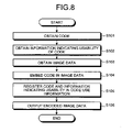
- FIG. 8 is a flowchart of a process performed by the code embedding device 100 according to the first embodiment.
- the code embedding unit 110 of the code embedding device 100 obtains the code from the input device 20 (step S 101 ), and the use information managing unit 120 obtains information indicating the usability of the code from the input device 20 (step S 102 ).
- the code embedding unit 110 then obtains image data from the image input device 30 (step S 103 ) and embeds the code in the image data (step S 104 ).
- the use information managing unit 120 obtains the code embedded in the image from the code embedding unit 110 and registers the information indicating the usability of the code in the code use information 130 a (step S 105 ).
- the code embedding unit 110 outputs encoded image data to the printing device 40 (step S 106 ).
- the use information managing unit 120 of the code embedding device 100 creates the code use information that restricts the code embedded in the image data, and registers the created code use information in the storage unit 130 , the code embedded in the image can be prevented from being used unrestrictedly.
- FIG. 9 is a flowchart of a process performed by the code authenticating device 200 according to the first embodiment.
- the code extraction processor 210 of the code authenticating device 200 obtains image data from the image input device 35 (step S 201 ) and extracts the code embedded in the image data (step S 202 ).
- the code extraction processor 210 then sends the extracted code to the code use information obtaining unit 220 and the usability determining unit 240 (step S 203 ).
- the code use information obtaining unit 220 requests information indicating the usability of the code from the code authenticating device 200 (step S 204 ), obtains the information indicating the usability of the code from the code authenticating device 200 , and sends the obtained information to the usability determining unit 240 (step S 205 ).
- the usability determining unit 240 determines whether the code obtained from the code extraction processor 210 can be used based on the information indicating the usability of the code obtained from the usability determining unit 240 (step S 206 ), and outputs the determination result to the display device 50 (step S 207 ).
- the usability determining unit 240 determines that the code extracted by the code extraction processor 210 cannot be used, it displays “This code cannot be used” on the display device 50 .
- the usability determining unit 240 determines that the code extracted by the code extraction processor 210 can be used, it displays “This code can be used” on the display device 50 .
- the code extraction processor 210 of the code authenticating device 200 extracts the code from the image data
- the code use information obtaining unit 220 obtains the information indicating the usability of the code from the code embedding device 100
- the usability determining unit 240 determines whether the code can be used, thereby enabling the use of the code embedded in the printed matter to be restricted.
- the code embedding unit 110 obtains the code and the image data, embeds the code by using difference in the average density of the image data, and creates encoded image data.
- the use information managing unit 120 registers information indicating the usability of the code embedded by the code embedding unit 110 in the code use information 130 a .
- the code use information transmitter 140 retrieves the information indicating the usability from the code use information 130 a in response to a request from the code authenticating device 200 , and transmits it to the code authenticating device 200 . Therefore, it is possible to efficiently restrict use of the code that is embedded in the printed matter created by the code embedding device 100 . Furthermore, since the method of embedding the code in the image by using the difference in average density is not standardized in the manner of a two-dimensional code, falsification of the code embedded in the image can be prevented.
- the code extraction processor 210 of the code authenticating device 200 uses the difference in average density of the image data to extract the code from the image data created by the code embedding device 100 , and the code use information obtaining unit 220 obtains information indicating the usability of the code by requesting this information from the code embedding device. Based on the code and the information indicating the usability of the code, the usability determining unit 240 determines whether the code can be used, and outputs the determination result to the display device 50 . Therefore, the problem of the code embedded in the image being used unrestrictedly can be solved.
- FIG. 10 is a functional block diagram of the configuration of a code embedding device that enables the code use information 130 a to be updated.
- a code embedding device 300 includes a use information update unit 310 . Since other configurations and elements are the same as the code embedding device 100 shown in FIG. 2 , they are designated with like reference numerals and are not explained again.
- the use information update unit 310 is a processor that, when it obtains the code to be updated and new information indicating usability that corresponds to this code from the input device 20 , updates the code use information. For example, when the use information update unit 310 receives the code “0001” and information indicating “Unusable” from the input device 20 , it updates the code use information 130 a in FIG. 6 to a code use information 130 a in FIG. 11 .
- FIG. 11 is an example of the code use information in FIG. 6 after being updated.
- a manager of the code embedding device 300 inputs the code to be updated and the new information indicating the usability to the input device 20 .
- the manager or the like of the code embedding device 300 can update the code use information 130 a , the information indicating the usability of the code that is embedded in the image data can be updated efficiently.
- the code embedding device 100 according to the first embodiment described above registers information indicating the usability of the code as the code use information
- the code embedding device according to the second embodiment registers information indicating a use time-limit of the code (the time-limit until which use of the code is permitted) as the code use information.
- the code embedding device according to the second embodiment determines whether the code that is embedded in the image can be used based on the use time-limit of the code.
- the code embedding device registers the use time-limit of the code as code use information, and the code authenticating device determines whether to permit use of the code based on the use time-limit of the code, thereby solving problems such as unrestricted use of the code embedded in the image. Similar to the first embodiment, the code embedding device and the code authenticating device according to the second embodiment are connected via a network.
- FIG. 12 is a functional block diagram of the configuration of the code embedding device according to the second embodiment.
- a code embedding device 400 includes a use information managing unit 410 , a storage unit 420 , and a code use information transmitter 430 . Since other configurations and elements are the same as the code embedding device 100 shown in FIG. 2 , they are designated with like reference numerals and are not explained again.
- the use information managing unit 410 is a processor that obtains a code embedded in image data from the code embedding unit 110 , obtains information indicating the use time-limit of the code from the input device 20 , and, based on the information thus obtained, creates code use information.
- the use information managing unit 120 stores the created code use information in the storage unit 420 .
- the storage unit 420 stores the code use information 420 a .
- FIG. 13 is an example of a data structure of the code use information 420 a according to the second embodiment. As shown in FIG. 13 , the code use information 420 a includes “code” and “use time-limit”. In the example of FIG. 13 , the use time-limit of code “0001” is “Sep. 1, 2005”, and the use time-limit of code “0002” is “Sep. 30, 2005”.
- the code use information transmitter 430 is a processor that, when an inquiry indicating a use time-limit of a code is received from a code authenticating device, retrieves the information indicating the usability of the corresponding code from the code use information 420 a and transmits the retrieved information to the code authenticating device. For example, when the code use information transmitter 430 receives an inquiry relating to the use time-limit of the code “0001”, it transmits information indicating that the use time-limit of the code “0001” is “2005.9.1” to the code authenticating device.
- FIG. 14 is a functional block diagram of the configuration of a code authenticating device according to the second embodiment.
- a code authenticating device 500 includes a code use information obtaining unit 510 , a usability determining unit 520 , and a date managing unit 530 . Since other configurations and elements are the same as the code authenticating device 200 shown in FIG. 7 , they are designated with like reference numerals and are not explained again.
- the code use information obtaining unit 510 is a processor that, when it receives a code from the code extraction processor 210 , requests information indicating the use time-limit of the code from the code embedding device 400 shown in FIG. 12 . Specifically, when the code use information obtaining unit 510 obtains the code “0001” from the code extraction processor 210 , it requests information indicating the use time-limit of the code “0001” from the code embedding device 100 .
- the code use information obtaining unit 510 When the code use information obtaining unit 510 receives a reply from the code embedding device 400 (for example, the use time-limit of code “0001” is “2005.9.1”), it sends the received information to the usability determining unit 520 .
- the usability determining unit 520 is a processor that determines whether a code extracted by the code extraction processor 210 can be used. Specifically, the usability determining unit 520 obtains the code from the code extraction processor 210 , obtains information indicating the use time-limit of the code from the code use information obtaining unit 510 , and obtains information indicating the present year, month, and date (hereinafter, “date information”) from the date managing unit 530 (the date managing unit 530 is a processor that manages the present year, month, and date). When the code can be used, the usability determining unit 520 outputs information indicating that the code can be used to the display device 50 . When the code cannot be used, the usability determining unit 520 outputs information indicating that the code cannot be used to the display device 50 .
- the usability determining unit 520 obtains the code “0001” from the code extraction processor 210 , obtains information indicating that “the use time-limit of this code is 2005.9.1” from the code use information obtaining unit 510 , and obtains date information of “2005.8.20” from the date managing unit 530 , since the use time-limit has not been exceeded, the usability determining unit 240 determines that the code “0001” can be used.
- the usability determining unit 520 obtains the code “0001” from the code extraction processor 210 , obtains information indicating that “the use time-limit of this code is 2005.9.1” from the code use information obtaining unit 510 , and obtains date information of “2005.9.20” from the date managing unit 530 , since the use time-limit has been exceeded, the usability determining unit 240 determines that the code “0001” cannot be used.
- the usability determining unit 520 determines that the corresponding code can be used.
- FIG. 15 is a flowchart of a process performed by the code embedding device 400 according to the second embodiment.
- the code embedding unit 110 of the code embedding device 400 obtains a code from the input device 20 (step S 301 ), and the use information managing unit 410 obtains information indicating the use time-limit of the code from the input device 20 (step S 302 ).
- the code embedding unit 110 obtains the image data from the image input device 30 (step S 303 ), and embeds a code in the image data (step S 304 ).
- the use information managing unit 410 obtains the code embedded in the image data from the code embedding unit 110 and registers the code and information indicating the use time-limit of the code in the code use information 420 a (step S 305 ), and the code embedding unit 110 outputs the encoded image data to the printing device 40 (step S 306 ).
- the use information managing unit 410 of the code embedding device 400 creates code use information that restricts the code embedded in the image data and registers the created code use information (code use time-limit) in the storage unit 420 , the code embedded in the image data can be prevented from being used unrestrictedly.
- FIG. 16 is a flowchart of a process performed by the code authenticating device 500 according to the second embodiment.
- the code extraction processor 210 of the code authenticating device 500 obtains image data from the image input device 35 (step S 401 ) and extracts a code that is embedded in the image data (step S 402 ).
- the code extraction processor 210 sends the extracted code to the code use information obtaining unit 510 and the usability determining unit 520 (step S 403 ).
- the code use information obtaining unit 510 requests information indicating the use time-limit of the code from the code embedding device 400 (step S 404 ), obtains the information indicating the use time-limit of the code from the code embedding device 400 , and sends the obtained information to the usability determining unit 520 (step S 405 ).
- the usability determining unit 520 obtains information indicating the present year, month, and date from the date managing unit 530 (step S 406 ), determines whether the code can be used based on the information indicating the use time-limit of the code that is obtained from the code use information obtaining unit 510 (step S 407 ), and outputs the determination result to the display device 50 (step S 408 ).
- the usability determining unit 520 determines that the use time-limit of the code extracted by the code extraction processor 210 has been exceeded, it makes the display device 50 display “This code cannot be used”. On the other hand, when the usability determining unit 520 determines that the use time-limit of the code extracted by the code extraction processor 210 has not been exceeded, it makes the display device 50 display “This code can be used”.
- the code extraction processor 210 of the code authenticating device 500 extracts the code from the image data
- the code use information obtaining unit 510 obtains the information indicating the use time-limit of the code from the code embedding device 400
- the usability determining unit 520 determines whether the code can be used. Therefore, the use time-limit of the code that is embedded in the printed matter can be restricted.
- the code embedding unit 110 obtains the code and the image data, uses difference in the average density of the image data to embed the code, and creates encoded image data.
- the use information managing unit 410 registers the information indicating the use time-limit of the code embedded by the code embedding unit 110 in the code use information 420 a .
- the code use information transmitter 430 retrieves the information indicating the use time-limit corresponding to that code from the code use information 420 a in response to a request from the code authenticating device 500 , and transmits it to the code authenticating device 500 . Therefore, the code that is embedded in the printed matter created by the code embedding device 400 can be restricted efficiently.
- the code extraction processor 210 of the code authenticating device 500 uses the difference in average density of the image data to extract the code from the image data created by the code embedding device 400 , and the code use information obtaining unit 510 obtains information indicating the use time-limit of the code by making a request for the information from the code embedding device 400 . Based on the information indicating the use time-limit of the code and present date information, the usability determining unit 520 determines the usability of the code and outputs the determination result to the display device 50 . This solves the problem of the code embedded in the image data being used unrestrictedly.
- the code embedding device uses a method similar to that of the first embodiment to embed a code in image data, and stores information indicating the number of valid uses of the embedded coded as code use information.
- a code authenticating device extracts the code embedded in a printed matter that is printed by the code embedding device, obtains the code use information corresponding to the extracted code from the code embedding device, and determines whether the extracted code can be used, i.e., whether the number of valid uses is 0.
- the code embedding device registers information indicating the number of valid uses of the code as the code use information, and the code authenticating device determines whether to permit use of the code based on the number of valid uses of that code, it becomes possible to prevent the code embedded in the image from being used without permission. Similar to the first embodiment, it is assumed that the code embedding device and the code authenticating device according to the third embodiment are connected via a network.
- FIG. 17 is a functional block diagram of the configuration of the code embedding device according to the third embodiment.
- a code embedding device 600 includes a use information managing unit 610 , a storage unit 620 , a code use information transmitter 630 , and a use information update unit 640 . Since other configurations and elements are the same as the code embedding device 100 shown in FIG. 2 , they are designated with like reference numerals and are not explained again.
- the use information managing unit 610 is a processor that obtains a code embedded in image data, obtains information indicating the number of valid uses of the code from the input device 20 , and creates code use information based on the obtained information.
- the use information managing unit 610 stores the created code use information in the storage unit 620 .
- the storage unit 620 stores code use information 620 a .
- FIG. 18 is an example of a data structure of the code use information 620 a .
- the code use information 620 a includes “code” and “number of valid uses”. In the example of FIG. 18 , the number of valid uses of code “0001” is “10”, and the number of valid uses of code “0002” is “9”.
- the code use information transmitter 630 is a processor that, when it receives an inquiry relating to the number of valid uses of a code from a code authenticating device, retrieves the information indicating the number of valid uses of the corresponding code from the code use information 620 a , transmits the retrieved information to the code authenticating device, and subtracts 1 from the number of valid uses.
- the code use information transmitter 630 when the code use information transmitter 630 receives an inquiry relating to the number of valid uses of the code “0001”, it transmits information indicating that the number of valid uses of the code “0001” is “10” to the code authenticating device and subtracts 1 from the number of valid uses. In the above example, the code use information transmitter 630 changes the number of valid uses from “10” to “9”.
- the code use information transmitter 630 does not subtract (it leaves the number of valid uses at “0”).
- the use information update unit 640 is a processor that, when it obtains a code to be updated and new information indicating the number of valid uses of that code from the input device 20 , updates the code use information 620 a . For example, when the use information update unit 640 receives code “0001” and the number of valid uses “5” from the input device 20 , it updates the number of valid uses of the code “0001” in FIG. 18 from “10” to “5”.
- FIG. 19 is a functional block diagram of the configuration of a code authenticating device according to the third embodiment.
- a code authenticating device 700 includes a code use information obtaining unit 710 and a usability determining unit 720 . Since other configurations and elements are the same as the code authenticating device 200 shown in FIG. 7 , they are designated with like reference numerals and are not explained again.
- the code use information obtaining unit 710 is a processor that, when it receives a code from the code extraction processor 210 , requests information indicating the number of valid uses of the code from the code embedding device 600 shown in FIG. 17 . Specifically, when the code use information obtaining unit 710 obtains the code “0001” from the code extraction processor 210 , it requests information indicating the number of valid uses of the code “0001” from the code embedding device 600 .
- the code use information obtaining unit 710 When the code use information obtaining unit 710 receives a reply (for example, the number of valid uses for code “0001” is “10”) from the code embedding device 600 , it sends the received information to the usability determining unit 720 .
- a reply for example, the number of valid uses for code “0001” is “10”
- the usability determining unit 720 is a processor that determines whether a code extracted by the code extraction processor 210 can be used. Specifically, the usability determining unit 720 obtains a code from the code extraction processor 210 , and obtains code use information from the code use information obtaining unit 710 . When the usability determining unit 720 determines that the code can be used, it outputs information indicating that the code can be used to the display device 50 . When it determines that the code cannot be used, it outputs information indicating that the code cannot be used to the display device 50 .
- the usability determining unit 720 determines that the code “0001” can be used.
- the usability determining unit 720 obtains the code “0001” from the code extraction processor 210 and obtains information that indicates “0” as the number of valid uses from the code use information obtaining unit 710 , since the number of valid uses of the code “0001” is 0, the usability determining unit 720 determines that the code “0001” cannot be used.
- FIG. 20 is a flowchart of a process performed by the code embedding device 600 according to the third embodiment.
- the code embedding unit 110 of the code embedding device 600 obtains a code from the input device 20 (step S 501 ) and the use information managing unit 610 obtains information indicating the number of valid uses of the code from the input device 20 (step S 502 ).
- the code embedding unit 110 obtains image data from the image input device 30 (step S 503 ) and embeds the code in the image data (step S 504 ).
- the use information managing unit 610 obtains the code embedded in the image from the code embedding unit 110 , and registers the code and the information indicating the number of valid uses of the code in the code use information 620 a (step S 505 ).
- the code embedding unit 110 outputs encoded image data to the printing device 40 (step S 506 ).
- the use information managing unit 610 of the code embedding device 600 creates code use information that restricts the number of valid uses of the code that is embedded in the image data and registers the created code use information in the storage unit 620 , the code embedded in the image can be prevented from being used unrestrictedly.
- FIG. 21 is a flowchart of a process performed by the code authenticating device 700 according to the third embodiment.
- the code extraction processor 210 of the code authenticating device 700 obtains image data from the image input device 35 (step S 601 ) and extracts a code that is embedded in the image data (step S 602 ).
- the code extraction processor 210 sends the extracted code to the code use information obtaining unit 710 and the usability determining unit 720 (step S 603 ).
- the code use information obtaining unit 710 requests information indicating the number of valid uses of the code from the code embedding device 600 (step S 604 ), obtains the information indicating the number of valid uses of the code from the code embedding device 600 , and sends the obtained information to the usability determining unit 720 (step S 605 ).
- the usability determining unit 720 determines whether the number of valid uses is one or more (step S 606 ), and, when it is one or more (step S 607 : Yes), outputs the fact that the code can be used to the display device 50 (step S 608 ), and, when it is 0, outputs the fact that the code cannot be used to the display device 50 (step S 609 ).
- the code authenticating device 700 uses the code extraction processor 210 to extract the code from the image data, the code use information obtaining unit 710 obtains the number of valid uses of the code from the code embedding device 600 , and the usability determining unit 720 determines whether the code can be used. This enables the manager or the like to restrict the number of uses of the code embedded in the printed matter as he desires.
- the code embedding unit 110 obtains the code and the image data, uses the difference in average density of the image data to embed the code, and creates encoded image data.
- the use information managing unit 610 registers information indicating the number of valid uses of the code embedded by the code embedding unit 110 in the code use information 620 a .
- the code use information transmitter 630 retrieves the information indicating the number of valid uses of the corresponding code from the code use information 620 a , and transmits it to the code authenticating device 700 . This makes it possible to efficiently restrict the number of uses of the code that is embedded in the printed mater created by the code embedding device 600 .
- the code extraction processor 210 uses the difference in average density of the image data to extract the code from the image data created by the code embedding device 600 , and the code use information obtaining unit 710 obtains information indicating the number of valid uses of the code by making a request for the information from the code embedding device 600 .
- the usability determining unit 720 determines the usability of the code and outputs the determination result to the display device 50 , thereby solving the problem of the code embedded in the image data being used unrestrictedly.
- the code embedding device uses a method similar to that of the first embodiment to embed a code in image data. In addition, it randomly determines information indicating the usability of the embedded code and stores this information.
- the code embedding device receives a request for information indicating the usability of the code from a code authenticating device, it transmits the information indicating the usability of the code to the code authenticating device, randomly determines information indicating the usability of the code once again, and updates the information indicating the usability of the code.
- the code embedding device randomly determines and stores the information indicating the usability of the code, even if a plurality of identical codes are issued, the use frequencies of the codes can be restricted. For example, even if identical codes are issued to a plurality of customers, since the usability of the issued codes is randomly changed, the code embedding device according to the fourth embodiment can be used in implementing a raffle service or the like without creating special codes.
- the code embedding device and the code authenticating device according to the fourth embodiment are connected via a network. Since the code authenticating device according to the fourth embodiment is identical to the code authenticating device 200 according to the first embodiment, it will be not explained again.
- FIG. 22 is a functional block diagram of the configuration of the code embedding device according to the fourth embodiment.
- a code embedding device 800 includes a use information managing unit 810 , a usability creating unit 820 , a storage unit 830 , and a code use information transmitter 840 . Since other configurations and elements are the same as the code embedding device 100 shown in FIG. 2 , they are designated with like reference numerals and are not explained again.
- the use information managing unit 810 is a processor that, when it obtains a code embedded in image data from the code embedding unit 110 , requests information indicating the usability of the code from the usability creating unit 820 , and creates code use information based on the information indicating the usability of the code obtained from the usability creating unit 820 and the code obtained from the code embedding unit 110 .
- the usability creating unit 820 When the usability creating unit 820 receives the information indicating the usability of the code embedded in the image data from the use information managing unit 810 , it determines whether to make the usability of the code “Usable” or “Unusable”, and sends information that indicates the determined usability to the use information managing unit 810 .
- the usability creating unit 820 can use any random determination method to determine the usability of the code. For example, the usability of the code can be randomly determined by generating a random number and setting the usability of the code to “Usable” if the generated number is an odd number and to “Unusable” if the number is an even number.
- the use information managing unit 810 stores the created code use information in the storage unit 830 .
- the use information managing unit 810 obtains the code from the code use information transmitter 840 (when the code use information transmitter 840 receives an inquiry relating to the usability of the code from a code authenticating device, it sends the code to the use information managing unit 810 ), it once again requests information indicating the usability of the code from the usability creating unit 820 , and updates the information indicating the usability of the code obtained from the code use information transmitter 840 according to the information indicating the usability of the code obtained from the usability creating unit 820 .
- the storage unit 830 stores code use information 830 a .
- the data structure of the code use information 830 a is the same as that of the code use information 130 a shown in FIG. 6 , and will not be explained again.
- the code use information transmitter 840 is a processor that, when it receives an inquiry relating to the usability of a code from the code authenticating device, retrieves information indicating the usability of that code from the code use information 830 a and transmits the retrieved information to the code authenticating device.
- the code use information transmitter 840 receives an inquiry relating to the usability of the code from the code authenticating device, it sends the code that is the target of the inquiry to the use information managing unit 810 .
- FIG. 23 is a flowchart of a process performed by the code embedding device 800 according to the fourth embodiment.
- the code embedding unit 110 of the code embedding device 800 obtains a code from the input device 20 (step S 701 ) and obtains image data from the image input device 30 (step S 702 ).
- the code embedding unit 110 embeds the code in the image (step S 703 ).
- the usability creating unit 820 randomly determines usability for the code and sends information indicating the determined usability to the use information managing unit 810 (step S 704 ).
- the use information managing unit 810 registers the code and the information indicating the usability of the code in the code use information 830 a (step S 705 ), and the code embedding unit 110 outputs encoded image data to the printing device 40 (step S 706 ).
- the usability creating unit 820 randomly determines the information indicating the usability of the code and the use information managing unit 810 updates the information indicating the usability of the code registers in the code use information 830 a , even when a plurality of identical codes are issued, the usability of the codes can be restricted.
- FIG. 24 is a flowchart of a process performed by the code embedding device 800 according to the fourth embodiment when it receives a request for information indicating the usability of a code from a code authenticating device.
- the code use information transmitter 840 of the code embedding device 800 obtains a code from a code authenticating device (step S 801 ) and retrieves information indicating the usability of that code from the code use information 830 a (step S 802 ).
- the code use information transmitter 840 then transmits the information indicating the usability of the code to the code authenticating device (step S 803 ), and sends the code to the use information managing unit 810 (step S 804 ).
- the use information managing unit 810 requests information indicating the usability of the code from the usability creating unit 820 (step S 805 ).
- the usability creating unit 820 randomly determines usability for the code, and sends information that indicates the determined usability to the use information managing unit 810 (step S 806 ).
- the use information managing unit 810 updates the information indicating the usability in the code use information 830 a (step S 807 ).
- the code embedding device 800 receives a request for information indicating the usability of the code from the code authenticating device, after transmitting information indicating the usability of the code to the code authenticating device, the usability creating unit 820 randomly creates a usability and the use information managing unit 810 updates the code use information 830 a . Therefore, even when identical codes are embedded in a plurality of image data, use of the codes can be restricted.
- the code embedding unit 110 obtains the code and the image data, uses the difference in average density of the image data to embed the code, and thereby creates encoded image data.
- the usability creating unit 820 then randomly determines usability for the code, and the use information managing unit 810 registers the randomly determined usability information in the code use information 830 a . Therefore, even when a plurality of identical codes are issued, use of the codes can be restricted.
- the code embedding device uses a method similar to that of the first embodiment to embed a first code in the image data. In addition, it creates a two-dimensional code from a second code, and stores information indicating the usability of a third code including the first code and the second code.
- the code authenticating device extracts the first code embedded in the image data, obtains a second code by decoding a two-dimensional code, obtains information indicating the usability of a third code including the first code and the second code from the code embedding device, and determines whether the code is usable.
- the code embedding device uses two types of codes to increase the number of valid digits in the issued code. Since the code embedding device stores information indicating the usability of two types of codes, it can prevent unrestricted use of a code having an increased number of valid digits that includes the two types of codes. Similar to the first embodiment, the code embedding device and the code authenticating device according to the fifth embodiment are connected via a network.
- FIG. 25 is a functional block diagram of the configuration of the code embedding device according to the fifth embodiment.
- a code embedding device 900 includes a code embedding unit 910 , a two-dimensional code creating unit 920 , a code arranging unit 930 , a use information managing unit 940 , a storage unit 950 , and a code use information transmitter 960 . Since other configurations and elements are the same as the code embedding device 100 shown in FIG. 2 , they are not explained again.
- the code embedding unit 910 is a processor that obtains a first code from the input device 20 , obtains image data from the image input device 30 , and embeds the first code in the image data. Since the method for embedding the first code in the image data is the same as that of the code embedding unit 110 in the first embodiment, it will not be explained again.
- the code embedding unit 910 sends the image data that the first code is embedded in (encoded image data) to the code arranging unit 930 , and sends the first code that is embedded in the image data to the use information managing unit 940 .
- the two-dimensional code creating unit 920 is a two-dimensional code encoder that creates a two-dimensional code by encoding the second code obtained from the input device 20 .
- a two-dimensional code is made by encoding information as a two-dimensionally shaped combination.
- the two-dimensional code creating unit 920 sends the created two-dimensional code to the code arranging unit 930 , and sends the second code to the use information managing unit 940 .
- the code arranging unit 930 is a processor that arranges the encoded image data obtained from code embedding unit 910 , and the two-dimensional code obtained from the two-dimensional code creating unit 920 , at predetermined positions.
- the code arranging unit 930 outputs information indicating the encoded image data and the two-dimensional code that are arranged at predetermined positions to the printing device 40 , and makes the printing device 40 to print the information and the two-dimensional code.
- FIG. 26 is one example of a printed matter that is printed by the printing device 40 according to the fifth embodiment. As shown in FIG. 26 , an image in which the first code is embedded and the two-dimensional code are printed on the printed matter.
- the use information managing unit 940 is a processor that obtains the first code from the code embedding unit 910 , obtains the second code from the two-dimensional code creating unit 920 , obtains information indicating the usability of a third code including the first code and the second code from the input device 20 , and creates code use information based on the obtained information.
- the third code is made by appending the second code to the first code. For example, if the first code is “0000” and the second code is “1111”, the third code becomes “00001111”.
- the storage unit 950 stores the code use information 950 a .
- FIG. 27 is one example of the data structure of the code use information 950 a according to the fifth embodiment. As shown in FIG. 27 , the code use information 950 a includes third “codes” and “usability” for each code. In the example of FIG. 27 , it is indicated that third codes “00002222” and “11112222” are usable.
- the code use information transmitter 960 is a processor that, when it receives an inquiry regarding the usability of a third code from the code authenticating device, retrieves information indicating the usability of the corresponding third code from the code use information 950 a and transmits the retrieved information to the code authenticating device. For example, when the code use information transmitter 960 receives an inquiry regarding the usability of the third code “00002222” from a code authenticating device, it transmits information indicating that the third code “00002222” is usable to the code authenticating device (because, in FIG. 27 , the usability of code “00002222” is “Usable”).
- FIG. 28 is a functional block diagram of the configuration of the code authenticating device according to the fifth embodiment.
- a code authenticating device 1000 includes a code extraction processor 1010 , a decoder 1020 , a code use information obtaining unit 1030 , and a usability determining unit 1040 . Since other configurations and elements are the same as the code authenticating device 200 shown in FIG. 7 , they are not explained again.
- the code extraction processor 1010 obtains image data from the image input device 35 and extracts the first code from the obtained image data.
- the code extraction processor 1010 sends an extracted first code to the code use information obtaining unit 1030 and the usability determining unit 1040 .
- the decoder 1020 is a processor that decodes the two-dimensional code from the image input device 35 and extracts the second code.
- the decoder 1020 sends the extracted second code to the code use information obtaining unit 1030 and the usability determining unit 1040 .
- the code use information obtaining unit 1030 is a processor that obtains the first code from the code extraction processor 1010 , obtains the second code from the decoder 1020 , identifies the third code, and requests information indicating the usability of the third code from the code embedding device 900 . Specifically, when the code use information obtaining unit 1030 obtains a first code of “0000” and a second code of “1111”, it identifies the third code as “00001111” and requests information that indicates the usability of the third code “00001111” from the code embedding device 900 .
- the code use information obtaining unit 1030 When the code use information obtaining unit 1030 receives a reply from the code embedding device 900 (for example, code “00001111” is “Usable”), it sends the received information to the usability determining unit 1040 .
- the usability determining unit 1040 is a processor that obtains the first code from the code extraction processor 1010 , obtains the second code from the decoder 1020 , identifies the third code, obtains information indicating the usability of the third code from the code use information obtaining unit 1030 , and determines whether the third code can be used.
- the usability determining unit 1040 outputs the determination result to the display device 50 .
- the usability determining unit 1040 determines that the code “00001111” can be used.
- the usability determining unit 1040 determines that the code “00001111” cannot be used.
- FIG. 29 is a flowchart of a process performed by the code embedding device 900 according to the fifth embodiment.
- the code embedding unit 910 obtains a first code from the input device 20 (step S 901 )
- the two-dimensional code creating unit 920 obtains a second code from the input device 20 (step S 902 )
- the use information managing unit 940 obtains information indicating usability from the input device 20 (step S 903 ).
- the code embedding unit 910 obtains image data from the image input device 30 (step S 904 ), embeds the first code in the image data, sends encoded image data to the code arranging unit 930 , and sends the first code to the use information managing unit 940 (step S 905 ).
- the two-dimensional code creating unit 920 creates a two-dimensional code by encoding the second code, sends the two-dimensional code to the code arranging unit 930 , and sends the second code to the use information managing unit 940 (step S 906 ).
- the use information managing unit 940 then identifies the third code from the first code and the second code (step S 907 ), and registers information indicating the usability of the third code in the code use information 950 a (step S 908 ).
- the code arranging unit 930 arranges the encoded image data and the two-dimensional code (step S 909 ) and outputs the image data to the printing device 40 (step S 910 ).
- the code embedding unit 910 embeds the first code in the image data
- the two-dimensional code creating unit 920 encodes the second code to a two-dimensional code
- the use information managing unit 940 registers information indicating the usability of the third code. Therefore, the number of valid digits in the code can be increased while preventing the code from being used unrestrictedly.
- FIG. 30 is a flowchart of a process performed by the code authenticating device 1000 according to the fifth embodiment.
- the code extraction processor 1010 of the code authenticating device 1000 obtains the image data from the image input device 35 (step S 1001 ), extracts the first code, and sends the extracted first code to the code use information obtaining unit 1030 and the usability determining unit 1040 (step S 1002 ).
- the decoder 1020 obtains a two-dimensional code from the image input device 35 (step S 1003 ), extracts the second code from the two-dimensional code, and sends the extracted second code to the code use information obtaining unit 1030 and the usability determining unit 1040 (step S 1004 ).
- the code use information obtaining unit 1030 identifies the third code from the first code and the second code (step S 1005 ), requests information indicating the usability of the third code from the code embedding device 900 (step S 1006 ), obtains the information indicating the usability of the third code, and sends the obtained information to the usability determining unit 1040 (step S 1007 ).
- the usability determining unit 1040 determines whether the third code can be used (step S 1008 ), and outputs a determination result to the display device 50 (step S 1009 ). When the usability determining unit 1040 determines that the third code cannot be used, it makes the display device 50 display a message “This code cannot be used.” When the usability determining unit 1040 determines that the third code can be used, it makes the display device 50 display a message “This code can be used.”
- the code extraction processor 1010 of the code embedding device 100 extracts the first code
- the decoder 1020 extracts the third code
- the usability determining unit 1040 determines whether the third code can be used. It is therefore possible to restrict the use of that third code including the code that is embedded in the image data and a code that is embedded in a two-dimensional code.
- the code embedding unit 910 embeds the first code in the image data
- the two-dimensional code creating unit creates a two-dimensional code from the second code
- the use information managing unit 970 registers information that relates to the usability of the third code including the first code and the second code in the code use information 950 a . Therefore, the number of valid digits in the code can be easily increased, and use of the code can be restricted efficiently.
- the code embedding device uses a method similar to that of the first embodiment to embed a code in image data, obtains information that identifies a user of the code (hereinafter, “user ID”), and stores information indicating the usability of the code embedded in the image in correlation with the user ID.
- user ID information that identifies a user of the code
- the code authenticating device extracts the code that is embedded in the printed matter. In addition, it obtains a user ID of a user who uses this code, obtains information indicating whether the user who corresponds to this user ID can use the code from the code embedding device, and makes a determination.
- the code embedding device manages information indicating usability for each user ID, even if the code is the same. Therefore, even when the same code is issued for a plurality of users, use of the code can be restricted for each user.
- the code authenticating device determines whether the code can be used based on the code embedded in the printed matter and the user ID. Therefore, even when a plurality of users attempt to use the code by using the same steganography code, use of the code can be restricted for each individual user.
- FIG. 31 is a functional block diagram of the configuration of the code embedding device according to the sixth embodiment.
- a code embedding device 1100 includes a use information managing unit 1110 , a storage unit 1120 , and a code use information transmitter 1130 . Since other configurations and elements are the same as the code embedding device 100 shown in FIG. 2 , they are designated with like reference numerals and are not explained again.
- the use information managing unit 1110 is a processor that obtains the code that is embedded in the image data from the code embedding unit 110 , obtains a user ID that corresponds to this code and information indicating the usability of the code from the input device 20 , and creates code use information based on the obtained information.
- the use information managing unit 1110 stores the created code use information in the storage unit 1120 .
- the storage unit 1120 stores code use information 1120 a .
- FIG. 32 is one example of the data structure of the code use information 1120 a according to the sixth embodiment. As shown in FIG. 32 , this code use information 1120 a includes “code”, “user ID”, and “usability”. In the example of FIG. 32 , there are three user IDs for code “0000”, namely “000”, “001”, and “002”, while use of code “0000” is permitted only for user ID “001”.
- the code use information transmitter 1130 is a processor that, when it obtains a code and a user ID from the code authenticating device, retrieves information indicating the usability corresponding to the obtained code and the user ID from the code use information 1120 a , and transmits the retrieved information to the code authenticating device.
- the code use information transmitter 1130 when the code use information transmitter 1130 receives code “0000” and user ID “001” from the code authenticating device, it transmits information indicating that the code “0000” can be used by a user who is identified by the user ID “001” to the code authenticating device (because, in FIG. 32 , the usability of code “0000” for user ID “001” is “Usable”).
- FIG. 33 is a functional block diagram of the configuration of a code authenticating device 1200 according to the sixth embodiment.
- the code authenticating device 1200 includes a code use information obtaining unit 1210 and a usability determining unit 1220 . Since other configurations and elements are the same as the code embedding device 200 shown in FIG. 7 , they are designated with like reference numerals and are not explained again.
- the code use information obtaining unit 1210 is a processor that obtains a code from the code extraction processor 210 , obtains a user ID from an input device 60 , and requests information indicating the usability of the obtained code and the user ID from the code embedding device 1100 . Specifically, when the code use information obtaining unit 1210 obtains the code “0000” and the user ID “001”, it requests information indicating the usability of the code “0000” with respect to the user ID “001” from the code embedding device 1100 .
- the code use information obtaining unit 1210 When the code use information obtaining unit 1210 receives a reply from the code embedding device 1100 (for example, the code “0000” is “usable” for the user ID “001”), it sends the received information to the usability determining unit 1220 .
- the usability determining unit 1220 is a processor that obtains the code from the code extraction processor 210 , obtains the user ID from the input device 60 , obtain information indicating the usability with respect to the code and the user ID from the code use information obtaining unit 1210 , and determines whether the code extracted by the code extraction processor 210 can be used by the user who corresponds to the user ID obtained from the input device 60 .
- the usability determining unit 1220 obtains code “0000” from the code extraction processor 210 , obtains the user ID “001” from the input device 60 , and obtains information indicating that “code 0000 and user ID 001 are usable”, it determines that the code “0000” and the user ID “001” can be used.
- the usability determining unit 1220 obtains code “0000” from the code extraction processor 210 , obtains the user ID “001” from the input device 60 , and obtains information indicating that “code 0000 and user ID 001 are unusable”, it determines that the code “0000” and the user ID “001” cannot be used.
- FIG. 34 is a flowchart of a process performed by the code embedding device 1100 according to the sixth embodiment.
- the code embedding unit 110 obtains a code from the input device 20 (step S 1101 ), and the use information managing unit 1110 obtains a user ID and information indicating usability from the input device 20 (step S 1102 ).
- the code embedding unit 110 obtains image data from the image input device 30 (step S 1103 ), and embeds a code in the image data (step S 1104 ).
- the use information managing unit 1110 obtains the code from the code embedding unit 110 and registers information indicating the usability of the code and the user ID in the code use information 1120 a (step S 1105 ).
- the code embedding unit 110 outputs encoded image data to the printing device 40 (step S 1106 ).
- the use information managing unit 1110 of the code embedding device 1100 registers the information indicating the usability of the code and the user ID in the code use information 1120 a in this way, use of the code can be restricted for each user ID even when a plurality of identical codes are issued.
- FIG. 35 is a flowchart of a process performed by the code authenticating device 1200 according to the sixth embodiment.
- the code extraction processor 210 of the code authenticating device 1200 obtains the image data from the image input device 35 (step S 1201 ), and the code use information obtaining unit 1210 obtains a user ID from the input device 60 (step S 1202 ).
- the code extraction processor 210 extracts the code from the image data (step S 1203 ), and sends the extracted code to the code use information obtaining unit 1210 and the usability determining unit 1220 (step S 1204 ).
- the code use information obtaining unit 1210 requests information indicating the usability of the code and the user ID from the code embedding device 1100 (step S 1205 ), obtains the information indicating the usability of the code and the user ID, and sends the obtained information to the usability determining unit 1220 (step S 1206 ).
- the usability determining unit 1220 determines whether the code obtained from the code extraction processor 210 and the user ID obtained from the input device 60 can be used, based on the information obtained from the code use information obtaining unit 1210 (step S 1207 ), and outputs a determination result to the printing device 40 (step S 1208 ).
- this code authenticating device 1200 since the code extraction processor 210 extracts the code from the image data, and the usability determining unit 1220 determines whether the code and the user ID can be used, use of the code can be restricted for each user ID even when the code is the same.
- the code embedding unit 110 obtains the code and the image data, embeds the code by using the difference in average density of the image data, and creates encoded image data.
- the use information managing unit 1110 registers information that indicates the usability of the code and the user ID in the code use information 1120 a , and the code use information transmitter 1130 transmits the corresponding information to the code authenticating device 1200 in reply to a request therefrom. Therefore, even if the same code is issued to users, use of the code by each individual user can be restricted.
- the code extraction processor 210 extracts the code from the image data created by the code embedding device 100 by using the difference in average density of the image data.
- the code use information obtaining unit 1210 requests information that indicates the usability of the code and the user ID from the code embedding device 1100 , and obtains this information. Based on the information indicating the usability of the code and the user ID, the usability determining unit 1220 determines whether the code and the user ID can be used and outputs a determination result to the display device 50 . Therefore, even when the same code is used, use of the code can be restricted for each user.
- the code embedding device 1100 stores the information indicating the usability of the code and the user ID as the code use information, it is acceptable to use a telephone number, such as the number of a mobile telephone owner by the user, instead of the user ID.
- the code embedding device and the code authenticating device according to the first to the sixth embodiments described above can be applied in a point of sales (POS) system that is used in supermarkets, convenience stores, and the like, or in a server-client system and the like.
- POS point of sales
- code embedding device and the code authenticating device according to the first to the sixth embodiments are applied in a POS system.
- a manager of a supermarket uses the code embedding device beforehand to create encoded image data and code use information (information that allows use of the code, information that limits use of the code, or the like).
- the manager uses a computer that is connected to a network to transmit the encoded image data to a mobile terminal device of a customer (for example, a mobile telephone), and to transmit the embedded code and the code use information to a management server.
- the management server stores and manages codes in correlation with code use information.
- the manager changes the code use information, he uses the computer to access the management server, and updates the code use information.
- the manager checks the address of the mobile terminal device of the customer beforehand.
- the code authenticating device extracts the code from the image data read by the POS terminal, and requests code use information corresponding to the extracted code from the management server.
- the code authenticating device then obtains the code use information from the management server, determines whether the code that is embedded in the image data can be used, and reports the determination result to the POS terminal.
- the POS terminal subtracts a predetermined sum from the price of the product.
- the POS terminal does not discount the price of the product.
- the manager can accelerate sales of products and can restrict the use of codes (coupons), thereby solving the problem of failing to obtain intended profits due to multiple use of codes.
- the processes of the code embedding device and the code authenticating device according to the first to the sixth embodiments described above can be realized by making a computer execute programs prepared beforehand.
- An example of a computer that realizes the functions of the code embedding device and the code authenticating device will be explained next.
- FIG. 36 is a functional block diagram of the computer that realizes the functions of the code embedding device and the code authenticating device.
- a computer 1300 includes an input/output interface device 1310 , a network interface device 1320 , a RAM 1330 , an HDD 1340 , a ROM 1350 , and a CPU 1360 , these being connected to a bus 1370 .
- the input/output interface device 1310 connects an input device such as a mouse and a keyboard to an output device such as a display device and a printer.
- the network interface device 1320 communicates with other computers on the network by using predetermined communication protocols.
- the RAM 1330 is a memory that stores programs, execution midway results of programs and the like.
- the RAM 1330 records code data 1330 a , image data 1330 b , and code use information 1330 c .
- the code data 1330 a is information indicating the code embedded in the image data
- the image data is the image data that the code is embedded in.
- the code use information 1330 c corresponds to the code use information 130 a shown in FIG. 2 .
- the HDD 1340 is a disk device that stores programs and data.
- the HDD 1340 stores code use information 1340 a .
- This code use information 1340 a is read in the RAM 1330 by the CPU 1360 .
- the CPU 1360 reads the encoding program 1350 a from the ROM 1350 and executes it, whereby, as shown in FIG. 36 , the encoding program 1350 a functions as an encoding process 1360 a .
- the CPU 1360 embeds the code in the image data, and registers information indicating the usability of the embedded code in the code use information 1330 c.
- the CPU 1360 reads the decoding program 1350 b from the ROM 1350 and executes it, whereby, as shown in FIG. 36 , the decoding program 1350 b functions as a decoding process 1360 b .
- the CPU 1360 extracts the code from the image data, and determines whether the extracted code can be used based on the code use information 1330 c.
- the code embedding device and the code authenticating device are connected via a network
- the configuration is not limited to this.
- the code embedding device and the code authenticating device can be arranged as a single device.
- the use information update unit 310 can be provided, enabling the manager of the code embedding device to update the code use information 1330 c whenever necessary.
- the encoding device divides the image into a plurality of blocks, embeds data in the image based on the difference in characteristic quantities of adjacent blocks, and records use restriction information that restricts the use of the data embedded in the image. Therefore, this encoding device can prevent illegitimate falsification/use of the data that is embedded in the image.
- the encoding device divides the image into a plurality of blocks, embeds data in the image based on the difference in characteristic quantities of adjacent blocks, and records information that indicates whether use of the data embedded in the image is permitted as use restriction information. Therefore, it is possible to efficiently manage and restrict the usability of the data (code) embedded in the image.
- the encoding device randomly changes the information that indicates whether use of the data is permitted. Therefore, even if a plurality of identical data (codes) are issued, the use frequencies of the issued codes can be restricted.
- the decoding device divides the image into a plurality of blocks, extracts the data embedded in the image based on the difference in characteristic quantities of adjacent blocks, obtains the use restriction information that restricts the use of the extracted data, and determines, based on the obtained use restriction information, whether use of the data embedded in the image is permitted. Therefore, the decoding device can prevent unrestricted use of the data that is embedded in the image.
- a printed matter is made by printing an image created by the encoding device that divides the image into a plurality of blocks, embeds data in the image based on the difference in characteristic quantities of adjacent blocks, and records use restriction information that restricts the use of the data embedded in the image. Therefore, unrestricted use of the data that is embedded in the printed matter can be prevented.
Abstract
Description
Dl<Dr→“0”
Dl≧Dr→“1”
Claims (14)
Applications Claiming Priority (2)
| Application Number | Priority Date | Filing Date | Title |
|---|---|---|---|
| JP2005311223A JP4576318B2 (en) | 2005-10-26 | 2005-10-26 | Encoding device |
| JP2005-311223 | 2005-10-26 |
Publications (2)
| Publication Number | Publication Date |
|---|---|
| US20070092105A1 US20070092105A1 (en) | 2007-04-26 |
| US7664291B2 true US7664291B2 (en) | 2010-02-16 |
Family
ID=37686117
Family Applications (1)
| Application Number | Title | Priority Date | Filing Date |
|---|---|---|---|
| US11/350,718 Active 2027-11-05 US7664291B2 (en) | 2005-10-26 | 2006-02-10 | Encoding device, decoding device, and printed matter |
Country Status (3)
| Country | Link |
|---|---|
| US (1) | US7664291B2 (en) |
| EP (1) | EP1780670A1 (en) |
| JP (1) | JP4576318B2 (en) |
Families Citing this family (7)
| Publication number | Priority date | Publication date | Assignee | Title |
|---|---|---|---|---|
| JP4124783B2 (en) | 2005-08-30 | 2008-07-23 | 富士通株式会社 | Information embedding device and information embedding program |
| US8532299B2 (en) * | 2007-05-29 | 2013-09-10 | Denso Wave Incorporated | Method for producing two-dimensional code and reader for reading the two-dimensional code |
| US9083895B2 (en) * | 2013-05-29 | 2015-07-14 | Lenovo Enterprise Solutions (Singapore) Pte. Ltd. | Embedded document destination routing restrictions |
| EA031834B1 (en) * | 2015-07-01 | 2019-02-28 | Дмитрий Маринкин | Method for identifying authenticity of an item having security marking on its surface |
| CN110335189B (en) * | 2019-05-31 | 2024-01-16 | 平安科技(深圳)有限公司 | Method, device, computer equipment and storage medium for filling anti-counterfeiting information |
| US11014391B2 (en) * | 2019-09-16 | 2021-05-25 | Xerox Corporation | Security marks based on print job image with uniform printed background |
| US10882347B1 (en) | 2019-09-16 | 2021-01-05 | Xerox Corporation | Security marks based on print job image |
Citations (9)
| Publication number | Priority date | Publication date | Assignee | Title |
|---|---|---|---|---|
| US6175639B1 (en) * | 1997-02-24 | 2001-01-16 | Nec Corporation | Digital data encode system |
| US6215421B1 (en) * | 1998-11-25 | 2001-04-10 | Sony Corporation | Coding apparatus and method, decoding apparatus and method, data processing system, and storage medium |
| JP2002260099A (en) | 2001-03-05 | 2002-09-13 | Toshiba Tec Corp | Commodity sales data processor, portable electronic terminal, commodity sales system, and coupon discounting method and program |
| US20030187798A1 (en) | 2001-04-16 | 2003-10-02 | Mckinley Tyler J. | Digital watermarking methods, programs and apparatus |
| US6700989B1 (en) * | 1997-08-29 | 2004-03-02 | Fujitsu Limited | Device for generating, detecting, recording, and reproducing a watermarked moving image having a copy preventing capability and storage medium for storing program or the moving image |
| EP1480163A2 (en) | 2003-05-20 | 2004-11-24 | Fujitsu Limited | Watermarking apparatus, method and computer readable medium based on image characteristics |
| US20050069171A1 (en) | 1999-05-19 | 2005-03-31 | Rhoads Geoffrey B. | Embedded data in gaming objects for authentication and association of behavior information |
| JP2005117154A (en) | 2003-10-03 | 2005-04-28 | Canon Inc | Method and apparatus for embedding electronic watermark, method and apparatus for extracting electronic watermark, computer program capable of executing each of above method, and storage medium storing the same |
| US20050180596A1 (en) * | 2004-02-18 | 2005-08-18 | Yasushi Abe | Image processing method, image processing apparatus, program and recording medium that can reduce image quality degradation |
Family Cites Families (3)
| Publication number | Priority date | Publication date | Assignee | Title |
|---|---|---|---|---|
| JP2000115521A (en) * | 1998-10-05 | 2000-04-21 | Canon Inc | Information processor and picture data processing method |
| JP2004030404A (en) * | 2002-06-27 | 2004-01-29 | Oki Electric Ind Co Ltd | Secure print system |
| JP2004038243A (en) * | 2002-06-28 | 2004-02-05 | Dainippon Printing Co Ltd | Contents transaction method and system |
-
2005
- 2005-10-26 JP JP2005311223A patent/JP4576318B2/en active Active
-
2006
- 2006-02-10 US US11/350,718 patent/US7664291B2/en active Active
- 2006-02-10 EP EP06250744A patent/EP1780670A1/en not_active Withdrawn
Patent Citations (11)
| Publication number | Priority date | Publication date | Assignee | Title |
|---|---|---|---|---|
| US6175639B1 (en) * | 1997-02-24 | 2001-01-16 | Nec Corporation | Digital data encode system |
| US6700989B1 (en) * | 1997-08-29 | 2004-03-02 | Fujitsu Limited | Device for generating, detecting, recording, and reproducing a watermarked moving image having a copy preventing capability and storage medium for storing program or the moving image |
| US6215421B1 (en) * | 1998-11-25 | 2001-04-10 | Sony Corporation | Coding apparatus and method, decoding apparatus and method, data processing system, and storage medium |
| US20050069171A1 (en) | 1999-05-19 | 2005-03-31 | Rhoads Geoffrey B. | Embedded data in gaming objects for authentication and association of behavior information |
| JP2002260099A (en) | 2001-03-05 | 2002-09-13 | Toshiba Tec Corp | Commodity sales data processor, portable electronic terminal, commodity sales system, and coupon discounting method and program |
| US20030187798A1 (en) | 2001-04-16 | 2003-10-02 | Mckinley Tyler J. | Digital watermarking methods, programs and apparatus |
| EP1480163A2 (en) | 2003-05-20 | 2004-11-24 | Fujitsu Limited | Watermarking apparatus, method and computer readable medium based on image characteristics |
| US20040234139A1 (en) | 2003-05-20 | 2004-11-25 | Fujitsu Limited | Image data processing apparatus, image data processing method, and computer readable medium |
| JP2004349879A (en) | 2003-05-20 | 2004-12-09 | Fujitsu Ltd | Device, method, and program for image data processing |
| JP2005117154A (en) | 2003-10-03 | 2005-04-28 | Canon Inc | Method and apparatus for embedding electronic watermark, method and apparatus for extracting electronic watermark, computer program capable of executing each of above method, and storage medium storing the same |
| US20050180596A1 (en) * | 2004-02-18 | 2005-08-18 | Yasushi Abe | Image processing method, image processing apparatus, program and recording medium that can reduce image quality degradation |
Non-Patent Citations (1)
| Title |
|---|
| Christoph Dautzenberg, "Watermarking images", Department of Microelectronics and Electrical Engineering, Trinity College Dublin, Oct. 1994. |
Also Published As
| Publication number | Publication date |
|---|---|
| JP4576318B2 (en) | 2010-11-04 |
| US20070092105A1 (en) | 2007-04-26 |
| JP2007122238A (en) | 2007-05-17 |
| EP1780670A1 (en) | 2007-05-02 |
Similar Documents
| Publication | Publication Date | Title |
|---|---|---|
| US9576298B2 (en) | Coupon copy protection | |
| US7664291B2 (en) | Encoding device, decoding device, and printed matter | |
| JP2006301866A (en) | Privilege information management method and privilege information management system | |
| EP1300748A2 (en) | Method and system for managing, accessing and paying for the use of copyrighted electronic media | |
| CN100525365C (en) | Image processing apparatus and control method therefor | |
| JP5250657B2 (en) | System for controlling the distribution and use of digital work | |
| US20120197688A1 (en) | Systems and Methods for Verifying Ownership of Printed Matter | |
| JP4452706B2 (en) | Coupon issuing device and computer program | |
| US20220156873A1 (en) | Image synthesis device and method for embedding watermark | |
| JP7357893B2 (en) | Information processing device, user terminal, store terminal, information processing method, and program | |
| WO2021235268A1 (en) | Method for managing artwork, computer, and program | |
| JP2023007937A (en) | Management system and method for managing non-fungible token | |
| US8857711B2 (en) | Tracking customer loyalty information using an incremental information object | |
| JP6931502B2 (en) | Campaign management system | |
| US11816756B1 (en) | Anti-leak digital document marking system and method using distributed ledger | |
| US11954756B1 (en) | Anti-leak digital document marking system and method using distributed ledger | |
| KR102540699B1 (en) | A method for managing copyrighted data and an apparatus for the same | |
| JP6678972B1 (en) | Information management device and its program | |
| CA2751656C (en) | Coupon copy protection | |
| EP4231184A1 (en) | Method and system for printing verified copy of a non-fungible token | |
| JP2024014784A (en) | Information processing system, information processing method, and program for tokenizing real assets in digital space | |
| JP3105186U (en) | Point server system using serial numbers | |
| JP2019208114A (en) | Image forming apparatus and information processing system | |
| CN116645091A (en) | Method and system for certified product NFT printing | |
| JP2019207514A (en) | Image formation device and information processing system |
Legal Events
| Date | Code | Title | Description |
|---|---|---|---|
| AS | Assignment |
Owner name: FUJITSU LIMITED,JAPAN Free format text: ASSIGNMENT OF ASSIGNORS INTEREST;ASSIGNORS:CHIBA, HIROTAKA;NODA, TSUGIO;SIGNING DATES FROM 20060124 TO 20060125;REEL/FRAME:017559/0473 Owner name: FUJITSU LIMITED, JAPAN Free format text: ASSIGNMENT OF ASSIGNORS INTEREST;ASSIGNORS:CHIBA, HIROTAKA;NODA, TSUGIO;REEL/FRAME:017559/0473;SIGNING DATES FROM 20060124 TO 20060125 |
|
| STCF | Information on status: patent grant |
Free format text: PATENTED CASE |
|
| FEPP | Fee payment procedure |
Free format text: PAYOR NUMBER ASSIGNED (ORIGINAL EVENT CODE: ASPN); ENTITY STATUS OF PATENT OWNER: LARGE ENTITY |
|
| FPAY | Fee payment |
Year of fee payment: 4 |
|
| FPAY | Fee payment |
Year of fee payment: 8 |
|
| MAFP | Maintenance fee payment |
Free format text: PAYMENT OF MAINTENANCE FEE, 12TH YEAR, LARGE ENTITY (ORIGINAL EVENT CODE: M1553); ENTITY STATUS OF PATENT OWNER: LARGE ENTITY Year of fee payment: 12 |