US7665318B2 - Compressor controlling apparatus and method - Google Patents
Compressor controlling apparatus and method Download PDFInfo
- Publication number
- US7665318B2 US7665318B2 US11/094,781 US9478105A US7665318B2 US 7665318 B2 US7665318 B2 US 7665318B2 US 9478105 A US9478105 A US 9478105A US 7665318 B2 US7665318 B2 US 7665318B2
- Authority
- US
- United States
- Prior art keywords
- compressor
- compressors
- bypass
- outlet
- inlet
- Prior art date
- Legal status (The legal status is an assumption and is not a legal conclusion. Google has not performed a legal analysis and makes no representation as to the accuracy of the status listed.)
- Expired - Fee Related, expires
Links
Images


Classifications
-
- F—MECHANICAL ENGINEERING; LIGHTING; HEATING; WEAPONS; BLASTING
- F25—REFRIGERATION OR COOLING; COMBINED HEATING AND REFRIGERATION SYSTEMS; HEAT PUMP SYSTEMS; MANUFACTURE OR STORAGE OF ICE; LIQUEFACTION SOLIDIFICATION OF GASES
- F25B—REFRIGERATION MACHINES, PLANTS OR SYSTEMS; COMBINED HEATING AND REFRIGERATION SYSTEMS; HEAT PUMP SYSTEMS
- F25B49/00—Arrangement or mounting of control or safety devices
- F25B49/02—Arrangement or mounting of control or safety devices for compression type machines, plants or systems
- F25B49/022—Compressor control arrangements
-
- F—MECHANICAL ENGINEERING; LIGHTING; HEATING; WEAPONS; BLASTING
- F25—REFRIGERATION OR COOLING; COMBINED HEATING AND REFRIGERATION SYSTEMS; HEAT PUMP SYSTEMS; MANUFACTURE OR STORAGE OF ICE; LIQUEFACTION SOLIDIFICATION OF GASES
- F25B—REFRIGERATION MACHINES, PLANTS OR SYSTEMS; COMBINED HEATING AND REFRIGERATION SYSTEMS; HEAT PUMP SYSTEMS
- F25B13/00—Compression machines, plants or systems, with reversible cycle
-
- F—MECHANICAL ENGINEERING; LIGHTING; HEATING; WEAPONS; BLASTING
- F25—REFRIGERATION OR COOLING; COMBINED HEATING AND REFRIGERATION SYSTEMS; HEAT PUMP SYSTEMS; MANUFACTURE OR STORAGE OF ICE; LIQUEFACTION SOLIDIFICATION OF GASES
- F25B—REFRIGERATION MACHINES, PLANTS OR SYSTEMS; COMBINED HEATING AND REFRIGERATION SYSTEMS; HEAT PUMP SYSTEMS
- F25B41/00—Fluid-circulation arrangements
- F25B41/20—Disposition of valves, e.g. of on-off valves or flow control valves
-
- F—MECHANICAL ENGINEERING; LIGHTING; HEATING; WEAPONS; BLASTING
- F25—REFRIGERATION OR COOLING; COMBINED HEATING AND REFRIGERATION SYSTEMS; HEAT PUMP SYSTEMS; MANUFACTURE OR STORAGE OF ICE; LIQUEFACTION SOLIDIFICATION OF GASES
- F25B—REFRIGERATION MACHINES, PLANTS OR SYSTEMS; COMBINED HEATING AND REFRIGERATION SYSTEMS; HEAT PUMP SYSTEMS
- F25B2400/00—General features or devices for refrigeration machines, plants or systems, combined heating and refrigeration systems or heat-pump systems, i.e. not limited to a particular subgroup of F25B
- F25B2400/07—Details of compressors or related parts
- F25B2400/075—Details of compressors or related parts with parallel compressors
- F25B2400/0751—Details of compressors or related parts with parallel compressors the compressors having different capacities
-
- F—MECHANICAL ENGINEERING; LIGHTING; HEATING; WEAPONS; BLASTING
- F25—REFRIGERATION OR COOLING; COMBINED HEATING AND REFRIGERATION SYSTEMS; HEAT PUMP SYSTEMS; MANUFACTURE OR STORAGE OF ICE; LIQUEFACTION SOLIDIFICATION OF GASES
- F25B—REFRIGERATION MACHINES, PLANTS OR SYSTEMS; COMBINED HEATING AND REFRIGERATION SYSTEMS; HEAT PUMP SYSTEMS
- F25B2500/00—Problems to be solved
- F25B2500/26—Problems to be solved characterised by the startup of the refrigeration cycle
-
- F—MECHANICAL ENGINEERING; LIGHTING; HEATING; WEAPONS; BLASTING
- F25—REFRIGERATION OR COOLING; COMBINED HEATING AND REFRIGERATION SYSTEMS; HEAT PUMP SYSTEMS; MANUFACTURE OR STORAGE OF ICE; LIQUEFACTION SOLIDIFICATION OF GASES
- F25B—REFRIGERATION MACHINES, PLANTS OR SYSTEMS; COMBINED HEATING AND REFRIGERATION SYSTEMS; HEAT PUMP SYSTEMS
- F25B2600/00—Control issues
- F25B2600/01—Timing
-
- F—MECHANICAL ENGINEERING; LIGHTING; HEATING; WEAPONS; BLASTING
- F25—REFRIGERATION OR COOLING; COMBINED HEATING AND REFRIGERATION SYSTEMS; HEAT PUMP SYSTEMS; MANUFACTURE OR STORAGE OF ICE; LIQUEFACTION SOLIDIFICATION OF GASES
- F25B—REFRIGERATION MACHINES, PLANTS OR SYSTEMS; COMBINED HEATING AND REFRIGERATION SYSTEMS; HEAT PUMP SYSTEMS
- F25B2600/00—Control issues
- F25B2600/02—Compressor control
- F25B2600/026—Compressor control by controlling unloaders
- F25B2600/0261—Compressor control by controlling unloaders external to the compressor
-
- F—MECHANICAL ENGINEERING; LIGHTING; HEATING; WEAPONS; BLASTING
- F25—REFRIGERATION OR COOLING; COMBINED HEATING AND REFRIGERATION SYSTEMS; HEAT PUMP SYSTEMS; MANUFACTURE OR STORAGE OF ICE; LIQUEFACTION SOLIDIFICATION OF GASES
- F25B—REFRIGERATION MACHINES, PLANTS OR SYSTEMS; COMBINED HEATING AND REFRIGERATION SYSTEMS; HEAT PUMP SYSTEMS
- F25B2700/00—Sensing or detecting of parameters; Sensors therefor
- F25B2700/19—Pressures
- F25B2700/193—Pressures of the compressor
- F25B2700/1931—Discharge pressures
-
- F—MECHANICAL ENGINEERING; LIGHTING; HEATING; WEAPONS; BLASTING
- F25—REFRIGERATION OR COOLING; COMBINED HEATING AND REFRIGERATION SYSTEMS; HEAT PUMP SYSTEMS; MANUFACTURE OR STORAGE OF ICE; LIQUEFACTION SOLIDIFICATION OF GASES
- F25B—REFRIGERATION MACHINES, PLANTS OR SYSTEMS; COMBINED HEATING AND REFRIGERATION SYSTEMS; HEAT PUMP SYSTEMS
- F25B2700/00—Sensing or detecting of parameters; Sensors therefor
- F25B2700/19—Pressures
- F25B2700/193—Pressures of the compressor
- F25B2700/1933—Suction pressures
-
- F—MECHANICAL ENGINEERING; LIGHTING; HEATING; WEAPONS; BLASTING
- F25—REFRIGERATION OR COOLING; COMBINED HEATING AND REFRIGERATION SYSTEMS; HEAT PUMP SYSTEMS; MANUFACTURE OR STORAGE OF ICE; LIQUEFACTION SOLIDIFICATION OF GASES
- F25B—REFRIGERATION MACHINES, PLANTS OR SYSTEMS; COMBINED HEATING AND REFRIGERATION SYSTEMS; HEAT PUMP SYSTEMS
- F25B2700/00—Sensing or detecting of parameters; Sensors therefor
- F25B2700/21—Temperatures
- F25B2700/2104—Temperatures of an indoor room or compartment
-
- F—MECHANICAL ENGINEERING; LIGHTING; HEATING; WEAPONS; BLASTING
- F25—REFRIGERATION OR COOLING; COMBINED HEATING AND REFRIGERATION SYSTEMS; HEAT PUMP SYSTEMS; MANUFACTURE OR STORAGE OF ICE; LIQUEFACTION SOLIDIFICATION OF GASES
- F25B—REFRIGERATION MACHINES, PLANTS OR SYSTEMS; COMBINED HEATING AND REFRIGERATION SYSTEMS; HEAT PUMP SYSTEMS
- F25B2700/00—Sensing or detecting of parameters; Sensors therefor
- F25B2700/21—Temperatures
- F25B2700/2106—Temperatures of fresh outdoor air
Definitions
- the present invention relates to a compressor controlling apparatus and method, and, more particularly, to a compressor controlling apparatus and method that is capable of starting a compressor while pressure equilibrium is achieved.
- a compressor is mounted in an air conditioner or a refrigerator, as a part of a refrigerating cycle, to compress an operating fluid introduced into the compressor and to discharge the compressed operating fluid.
- FIG. 1 a shows the construction of an air conditioner with a conventional singular compressor mounted therein.
- An outlet pipe 3 of a compressor 1 is connected to an outdoor heat exchanger 10 via a four-way valve 9 .
- the outdoor heat exchanger 10 is connected to an expansion unit 11 via a coolant pipe, and the expansion unit 11 is also connected to an indoor heat exchanger 12 via another coolant pipe.
- An outlet of the indoor heat exchanger 12 is connected to an inlet of the compressor 1 via an accumulator 13 and a low-pressure pipe 8 . In this way, a closed circuit is formed in the air conditioner.
- FIG. 1 b shows the construction of an air conditioner with conventional plural compressors mounted therein.
- Outlet pipes 3 and 4 of compressors 1 and 2 are commonly connected to a high-pressure pipe 7 , which is connected to an outdoor heat exchanger 10 via a four-way valve 9 .
- the outdoor heat exchanger 10 is connected to an expansion unit 11 via a coolant pipe, and the expansion unit 11 is also connected to an indoor heat exchanger 12 via another coolant pipe.
- An outlet of the indoor heat exchanger 12 is connected to inlets of the compressors 1 and 2 via an accumulator 13 and a low-pressure pipe 8 . In this way, a closed circuit is formed in the air conditioner.
- the high-pressure pipe is commonly connected to the outlet pipes of these plural compressors. Consequently, when only one of the compressors is operated, high-pressure coolant gas that is discharged from the operated compressor may be introduced into the non-operated compressor.
- reverse-flow preventing check valves 5 and 6 are provided at the outlets of the plural compressors, as shown in FIG. 1 b.
- the presence of the check valves 5 and 6 do not completely prevent the introduction of the high-pressure coolant gas into the non-operated compressor. As a result, some of the coolant gas is introduced into the non-operated compressor through the corresponding check valve.
- the pressure at the outlet of the non-operated compressor is higher than usual.
- the pressure inside the non-operated compressor is also high.
- an outlet valve which serves to supply compressed coolant to the outlet pipe, is not opened when the non-operated compressor is started. Consequently, the compressor is poorly started, and reliability of the compressor is deteriorated.
- an aspect of the invention provides a compressor controlling apparatus and method capable of starting a non-operated compressor while pressure equilibrium is achieved to prevent poor start-up of the compressor caused due to excessive pressure difference between an outlet and an inlet of the compressor so as to reliability of the compressor.
- the present invention provides a compressor controlling apparatus, comprising: a compressor; a bypass unit connected between an outlet and an inlet of the compressor; and a control unit to reduce a pressure difference between the outlet and the inlet of the compressor via the bypass unit to start the compressor when the compressor is to be started.
- the present invention provides a compressor controlling apparatus, comprising: a compressor; a bypass unit connected between an outlet and an inlet of the compressor; a pressure equilibrium determining unit to determine whether a pressure equilibrium between the inlet and the outlet of the compressor is achieved; and a control unit to reduce a pressure difference between the outlet and the inlet of the compressor via the bypass unit to start the compressor if the pressure equilibrium determining unit determines that the pressure equilibrium is not achieved when the compressor is to be started.
- the present invention provides a compressor controlling apparatus, comprising: plural compressors connected to each other in parallel; a bypass unit connected between an outlet and an inlet of at least one of the compressors; and a control unit to reduce a pressure difference between the outlet and the inlet of the non-operated compressor via the bypass unit to start the non-operated compressor when the non-operated compressor is to be started.
- the present invention provides a compressor controlling apparatus, comprising: plural compressors connected to each other in parallel; a bypass unit connected between an outlet and an inlet of at least one of the compressors; a pressure equilibrium determining unit to determine whether a pressure equilibrium between the inlet and the outlet of the compressor with the bypass unit mounted thereto is achieved; and a control unit to reduce a pressure difference between the outlet and the inlet of the compressor via the bypass unit to start the non-operated compressor if the pressure equilibrium determining unit determines that the pressure equilibrium is not achieved when the non-operated compressor is to be started.
- the present invention provides a compressor controlling method of a compressor having a bypass unit connected between an outlet and an inlet of the compressor and a control unit, wherein the method comprises: determining whether the compressor is to be started; reducing a pressure difference between the outlet and inlet of the compressor via the bypass unit to achieve a pressure equilibrium when the compressor is to be started; and starting the compressor while the pressure equilibrium is achieved.
- the present invention provides a compressor controlling method of a compressor having a bypass unit connected between an outlet and an inlet of the compressor, a pressure equilibrium determining unit to determine whether pressure equilibrium between the inlet and the outlet of the compressor is achieved, and a control unit, wherein the method comprises: determining whether the compressor is to be started; determining whether the pressure equilibrium is achieved for the compressor via the pressure equilibrium determining unit when the compressor is to be started; reducing a pressure difference between the outlet and inlet of the compressor via the bypass unit to achieve pressure equilibrium when the pressure equilibrium between the inlet and the outlet of the compressor is determined to not have been achieved; and starting the compressor while the pressure equilibrium is achieved.
- the present invention provides a compressor controlling method of plural compressors having a bypass unit connected between an outlet and an inlet of at least one of the compressors and a control unit, wherein the method comprises: determining whether the compressors are to be started; initially starting the compressor with no bypass unit mounted thereto when the compressors are to be started; reducing a pressure difference between the outlet and inlet of the compressor with the bypass unit mounted thereto via the bypass unit to achieve pressure equilibrium when the compressor with the bypass unit mounted thereto is to be started; and starting the compressor with the bypass unit mounted thereto while the pressure equilibrium is achieved.
- FIGS. 1 a and 1 b are views respectively showing the construction of an air conditioner with a conventional compressor(s) mounted therein;
- FIGS. 2 a and 2 b are views respectively showing the structure of a compressor to which the present invention is applied;
- FIG. 2 c is a table showing results of start-up tests of a non-operated compressor on the basis of a pressure difference
- FIG. 3 a is a view of a compressor controlling apparatus according to a first embodiment of the present invention showing a bypass unit applied to a singular compressor;
- FIG. 3 b is a control block diagram of FIG. 3 a;
- FIG. 3 c is a flow chart showing a compressor controlling method according to a first embodiment of the present invention.
- FIG. 4 a is a view of a compressor controlling apparatus according to a second embodiment of the present invention showing a bypass unit and pressure sensors applied to a singular compressor;
- FIG. 4 b is a control block diagram of FIG. 4 a;
- FIG. 4 c is a flow chart showing a compressor controlling method according to a second embodiment of the present invention.
- FIG. 5 a is a view of a compressor controlling apparatus according to a third embodiment of the present invention showing bypass units applied to plural compressors;
- FIG. 5 b is a control block diagram of FIG. 5 a
- FIG. 5 c is a flow chart showing a compressor controlling method according to a third embodiment of the present invention.
- FIG. 6 a is a view of a compressor controlling apparatus according to a fourth embodiment of the present invention showing a bypass unit applied to a large-capacity compressor, one of plural compressors;
- FIG. 6 b is a control block diagram of FIG. 6 a
- FIG. 6 c is a view of a compressor controlling apparatus according to a fourth embodiment of the present invention showing a bypass unit applied to a small-capacity compressor, one of plural compressors;
- FIG. 6 d is a control block diagram of FIG. 6 c
- FIGS. 6 e and 6 f are flow charts showing a compressor controlling method according to a fourth embodiment of the present invention.
- FIG. 7 a is a view of a compressor controlling apparatus according to a fifth embodiment of the present invention showing bypass units and pressure sensors applied to plural compressors;
- FIG. 7 b is a control block diagram of FIG. 7 a ;
- FIGS. 7 c and 7 d are flow charts showing a compressor controlling method according to a fifth preferred embodiment of the present invention.
- First to fifth embodiments of the present invention are all applied to an air conditioner.
- the present invention is not restricted to the air conditioner.
- the present invention may be applied to a refrigerator with a compressor mounted therein.
- a compressor 20 to which the present invention is applied includes an inlet 21 connected to one end of a low-pressure pipe 8 to allow low-pressure coolant from an accumulator 13 to be introduced into the compressor 20 therethrough, as shown in FIG. 2 a.
- the coolant introduced through the inlet 21 is compressed and expanded in a cylinder 23 , and is then discharged from the cylinder 23 .
- the high-pressure coolant is guided into a discharging chamber 24 formed at the upper part of the compressor 20 , and is then discharged from the discharging chamber 24 through an outlet 3 , 4 , one end of which extends downward into the discharging chamber 24 .
- FIG. 2 c Start-up tests of the compressor based on a pressure difference have been performed, results of which are shown in FIG. 2 c . It can be seen from FIG. 2 c that the compressor has been smoothly started when the pressure difference between the outlet and the inlet of the compressor is not more than 1.5 kgf/cm 2 .
- FIG. 3 a is a view of a compressor controlling apparatus according to a first embodiment of the present invention showing a bypass unit applied to a singular compressor.
- a compressor 1 , an outdoor heat exchanger 10 , an expansion unit 11 , an indoor heat exchanger 12 , and an accumulator 13 are connected to each other via coolant pipes so as to form a closed circuit.
- An outlet pipe 3 of the compressor 1 is connected to a four-way valve 9 .
- a first bypass unit 30 which is also connected to the inlet of the compressor 1 , is connected to the compressor 1 .
- the first bypass unit 30 has a first bypass valve 32 on a first bypass line 31 that is connected between the outlet and the inlet of the compressor 1 .
- FIG. 3 b is a control block diagram of FIG. 3 a .
- a first bypass valve driving unit 111 opens/closes the first bypass valve 32 according to control of a control unit 105 .
- FIG. 3 c is a flow chart showing a compressor controlling method according to the first embodiment of the present invention.
- the control unit 105 initializes the air conditioner, calculates operation load using an indoor temperature sensor 101 and an outdoor temperature sensor 103 , and determines whether the compressor is to be started ( 121 , 123 and 125 ).
- the control unit 105 opens the first bypass valve 32 for a prescribed period of time so that pressure difference between the outlet and the inlet of the compressor is reduced ( 127 and 129 ).
- the time required to open the bypass valve is set to more than the minimum time necessary to achieve a state in which a pressure equilibrium is reached between inlet and outlet pressures of the compressor within a normal operation range.
- the control unit 105 closes the first bypass valve 32 , and then starts the compressor 1 ( 131 ).
- the control unit 105 stops the operation of the compressor via a timer T, measures a compressor stopping time, and determines whether the non-operated compressor is to be started on the basis of the calculated operational load ( 137 , 139 and 141 ).
- the control unit 105 determines whether the measured compressor stopping time exceeds a prescribed period of time. When the measured compressor stopping time is determined to exceed the prescribed period of time, i.e., when a pressure equilibrium is determined to have been achieved, the procedure is returned to operation 131 so that the compressor may be started. When the measured compressor stopping time is determined to not exceed the prescribed period of time, on the other hand, the control unit 105 opens the first bypass valve, and the procedure is returned to operation 127 ( 143 ).
- the compressor stopping time is measured to determine whether the pressure equilibrium is achieved, although starting the compressor after the bypass valve is opened constantly for a prescribed period of time without determining whether the pressure equilibrium is achieved may be possible.
- determining whether the pressure equilibrium is achieved by directly sensing the pressure difference using inlet and outlet pressure sensors is also possible.
- FIG. 4 a is a view of a compressor controlling apparatus according to a second embodiment of the present invention showing a first bypass unit 30 and pressure sensors 3 a and 3 b that are applied to a singular compressor.
- the pressure sensors are mounted to the outlet and the inlet of the compressor to provide signals that are representative of outlet and inlet pressures to a control unit 105 a (See FIG. 4 b ).
- the control unit 105 determines whether the pressure equilibrium is achieved based on the signal from the pressure sensors.
- the first bypass unit 30 has a first bypass valve 32 on a first bypass line 31 that is connected between the outlet and the inlet of the compressor 1 .
- a first bypass valve driving unit 111 opens/closes the first bypass valve 32 according to control of the control unit 105 a (See FIG. 4 b ).
- the control unit 105 a determines whether the pressure equilibrium is achieved through the use of the pressure sensors before the compressor is started, and performs operations that are necessary to reduce the pressure difference through the use of the bypass unit according to the determination.
- FIG. 4 c is a flow chart showing a compressor controlling method according to a second embodiment of the present invention.
- the control unit 105 a initializes the air conditioner, and determines whether the compressor is to be started on the basis of calculated operation load ( 151 , 153 and 155 ).
- the control unit 105 a calculates the pressure difference between the outlet and the inlet of the compressor through the use of the first outlet pressure sensor 3 a and the first inlet pressure sensor 3 b , and compares the calculated pressure difference to a prescribed value to determine whether the pressure equilibrium is achieved ( 157 and 159 ). When the pressure equilibrium is determined to not have been achieved, the control unit 105 a opens the first bypass valve 32 ( 160 ).
- control unit 105 a closes the first bypass valve 32 , and then starts the compressor ( 161 ).
- the control unit 105 a stops the operation of the compressor via a timer T, measures compressor stopping time, and determines whether the non-operated compressor is to be started based on calculated operational load ( 167 , 169 and 171 ).
- the control unit 105 a determines whether the measured compressor stopping time exceeds a prescribed period of time.
- the procedure is returned to operation 161 .
- the procedure is returned to operation 160 ( 173 ).
- the compressor stopping time is measured to determine whether the pressure equilibrium is achieved, although starting the compressor after the bypass valve is opened constantly for a prescribed period of time without determining whether the pressure equilibrium is achieved may be possible. Determining whether the pressure equilibrium is achieved by directly sensing the pressure difference using inlet and outlet pressure sensors may also be possible.
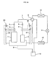
- FIG. 5 a is a view of a compressor controlling apparatus according to a third embodiment of the present invention showing bypass units applied to plural compressors.
- the plural compressors include a large-capacity compressor 1 and a small-capacity compressor 1 connected to the large-capacity compressor 1 in parallel, although the plural compressors have the same capacity.
- outlet pipes 3 and 4 of the plural compressors 1 and 2 are commonly connected to a high-pressure pipe 7 .
- Reverse-flow preventing check valves 5 and 6 are mounted on the outlet pipes 3 and 4 , respectively.
- the compressor controlling apparatus includes a first bypass unit 30 that is connected between the outlet and the inlet of the compressor 1 and a second bypass unit 40 that is connected between the outlet and the inlet of the compressor 2 .
- the first bypass unit 30 has a first bypass valve 32 on a first bypass line 31 connected between the outlet and the inlet of the large-capacity compressor 1 .
- the second bypass unit 40 has a second bypass valve 42 on a second bypass line 41 connected between the outlet and the inlet of the small-capacity compressor 1 .
- the first and second bypass valves 32 and 42 are opened/closed according to control of a control unit 105 b (See FIG. 5 b ).
- the control unit 105 b properly controls the first and second bypass valves 32 and 42 so that a poor start-up of the plural compressor is prevented.
- FIG. 5 c is a flow chart showing a compressor controlling method according to a third embodiment of the present invention.
- the control unit 105 b calculates operational load based on indoor and outdoor temperatures sensed via temperature sensors 101 and 103 , and determines whether all the plural compressors are to be operated according to the calculated operational load ( 201 , 203 and 205 ).
- the control unit 105 b opens the second bypass valve 42 that is mounted to the small-capacity compressor 2 ( 207 ), measures valve opening time via an inner timer, and determines whether the measured valve opening time exceeds a prescribed period of time ( 209 ).
- the control unit 105 b closes the second bypass valve 42 , and starts the small-capacity compressor 2 ( 211 ). Thereafter, the compressor is normally operated ( 213 ).
- the control unit 105 b opens the first and second bypass valves 32 and 42 ( 215 ), and determines whether the valve opening time measured via the inner timer exceeds the prescribed period of time ( 217 ). When the measured valve opening time is determined to exceed the prescribed period of time, the control unit 105 b closes the first and second bypass valves 32 and 42 , and starts the plural compressors in sequence ( 219 ). Thereafter, the compressors are normally operated ( 221 ).
- the control unit 105 a stops the operation of the compressors, measures compressor stopping time via a timer T, and determines whether the non-operated compressors are to be started on the basis of calculated operational load ( 225 , 227 and 229 ). Since determining whether the pressure equilibrium is achieved when one of the plural compressors is operated while the other of the plural compressor is stopped may be difficult, the compressor stopping time is measured while all the plural compressors are stopped.
- the control unit 105 a determines whether the measured compressor stopping time exceeds a prescribed period of time. When the measured compressor stopping time is determined to exceed the prescribed period of time, the procedure proceeds to operation 233 so that the corresponding compressor(s) is/are started. When the measured compressor stopping time is determined to not exceed the prescribed period of time, on the other hand, the procedure is returned to operation 205 ( 231 ).
- FIG. 6 a is a view of a compressor controlling apparatus according to a fourth embodiment of the present invention showing a third bypass unit 50 applied to a large-capacity compressor 1 , which may represent one of at least two plural compressors
- FIG. 6 c is a view of the compressor controlling apparatus according to a fourth embodiment of the present invention showing a fourth bypass unit 60 applied to a small-capacity compressor 2 , the other of plural compressors.
- the third bypass unit 50 is mounted to the large-capacity compressor 1 .
- the small-capacity compressor 2 is initially operated. As an operational load is increased, operating the large-capacity compressor 1 , which is not operated, is necessary.
- a control unit 106 opens a third bypass valve 52 of the third bypass unit 50 so that the pressure difference between the outlet and the inlet of the compressor 1 is reduced (Also see FIG. 6 b ).
- the fourth bypass unit 60 is mounted to the small-capacity compressor 2 .
- the large-capacity compressor 1 is initially operated. As an operational load is increased, operating the small-capacity compressor 2 , which is not operated, becomes necessary.
- the control unit 106 opens a fourth bypass valve 62 of the fourth bypass unit 60 so that the pressure difference between the outlet and the inlet of the compressor 2 is reduced (Also see FIG. 6 d ).
- FIGS. 6 e and 6 f are flow charts showing a compressor controlling method according to a fourth embodiment of the present invention.
- the control unit 106 initializes the air conditioner, calculates an operational load on the basis of indoor and outdoor temperatures sensed by temperature sensors 101 and 103 , and determines whether all the plural compressors are to be operated according to the calculated operational load ( 301 , 303 and 305 ).
- control unit 106 starts the compressor with no bypass unit mounted thereto ( 307 ). After the start-up of the compressor with no bypass unit mounted thereto is completed, the control unit 106 calculates an operational load again, and determines whether all the plural compressors are to be operated according to the calculated operational load ( 309 ). When not all the compressors are to be operated, the compressor is normally operated ( 311 ).
- the control unit 106 opens the bypass valve of the compressor with the bypass unit mounted thereto ( 313 ), measures valve opening time by an inner timer, and determined whether the measured valve opening time exceeds a prescribed period of time ( 315 ). When the measured valve opening time exceeds a prescribed period of time, the control unit 106 closes the bypass valve, and starts the compressor with no bypass unit mounted thereto and the compressor with the bypass unit mounted thereto in sequence ( 317 ). Thereafter, the compressors are normally operated ( 319 ).
- the control unit 106 stops the operation of the compressor(s), measures compressor stopping time by a timer T, and determines whether the stopped compressor(s) is to be started on the basis of the calculated operational load ( 323 , 325 and 327 ).
- the control unit 106 determines whether the measured compressor stopping time exceeds a prescribed period of time.
- the procedure proceeds to operation 331 so that the corresponding compressor(s) may be started.
- the control unit 106 the procedure is returned to operation 305 ( 329 ).
- the compressor stopping time is measured to determine whether the pressure equilibrium is achieved, although starting the compressor(s) after the bypass valve(s) is opened constantly for a prescribed period of time without determining whether the pressure equilibrium is achieved may be possible.
- determining whether the pressure equilibrium is achieved by directly sensing the pressure difference using inlet and outlet pressure sensors of compressors is also possible.
- FIG. 7 a is a view of a compressor controlling apparatus according to a fifth embodiment of the present invention showing bypass units and pressure sensors applied to plural compressors.
- a first bypass unit 30 a first outlet pressure sensor 3 a , and a first inlet pressure sensor 3 b are mounted to the large capacity compressors, which is one of the compressors.
- a second bypass unit 40 , a second outlet pressure sensor 4 a , and a second inlet pressure sensor 4 b are mounted to the small capacity compressor, which is the other compressor.
- a control unit 108 determines whether the pressure difference between the outlet pressure and the inlet pressure of the compressor(s), which is sensed by the sensors, is below a prescribed value (See FIG. 7 b ). When the pressure difference is determined to be below the prescribed value, the control unit 108 closes the bypass valve(s), and starts the compressor(s).
- FIGS. 7 c and 7 d are flow charts showing a compressor controlling method according to a fifth embodiment of the present invention.
- the control unit 108 initializes the air conditioner, calculates operational load based on indoor and outdoor temperatures sensed by temperature sensors 101 and 103 , and determines whether the compressors are to be operated according to the calculated operational load ( 401 , 402 and 403 ).
- the control unit 108 calculates the pressure difference between the outlets and the inlets of the compressors by the outlet pressure sensors 3 a and 4 a and the inlet pressure sensors 3 b and 4 b , and compares the pressure difference with a prescribed valve to determine whether pressure equilibrium is achieved ( 404 and 405 ).
- the control unit 108 determines whether all the compressors are to be operated based on the calculated operational load ( 406 ). When not all the compressors are to be operated, the control unit 108 opens a second bypass valve 42 mounted to the small-capacity compressor 2 , calculates pressure difference between the outlets and the inlets of the compressors by the outlet pressure sensors 3 a and 4 a and the inlet pressure sensors 3 b and 4 b , and determines whether the calculated pressure difference is below the prescribed value, i.e., whether the pressure equilibrium is achieved ( 409 and 411 ). When the pressure difference is determined to be below the prescribed value, the control unit 108 closes the second bypass valve 42 , and starts the small-capacity compressor ( 413 ). Thereafter, the compressor is normally operated ( 415 ).
- the control unit 108 opens a first bypass valve 32 mounted to the large-capacity compressor as well as the second bypass valve 42 , calculates pressure difference between the outlets and the inlets of the compressors by the outlet pressure sensors 3 a and 4 a and the inlet pressure sensors 3 b and 4 b , and determines whether the calculated pressure difference is below the prescribed value, i.e., whether the pressure equilibrium is achieved ( 419 and 421 ).
- the control unit 108 closes the first and second bypass valves 32 and 42 , and starts the compressors in sequence ( 423 ). Thereafter, the compressors are normally operated ( 425 ).
- the control unit 108 starts the compressors in which the pressure equilibrium is achieved ( 408 ). Whether the operation of the compressors is to be stopped during the normal operation of the compressors ( 410 and 412 ) is then determined.
- the control unit 108 stops the operation of the compressors, measures compressor stopping time by a timer T, and determines whether the stopped compressors are to be started based on calculated operational load ( 414 , 416 and 418 ).
- the control unit 108 determines whether the measured compressor stopping time exceeds a prescribed period of time.
- the procedure is returned to operation 408 ( 420 ).
- the procedure is returned to operation 406 .
- the compressor stopping time is measured to determine whether the pressure equilibrium is achieved, although starting the compressor(s) after the bypass valve(s) is opened constantly for a prescribed period of time without determining whether the pressure equilibrium is achieved may be possible. Determining whether the pressure equilibrium is achieved by directly sensing the pressure difference using inlet and outlet pressure sensors is also possible.
- the present invention provides a compressor controlling apparatus and method that is capable of achieving pressure equilibrium between outlet pressure and inlet pressure of a non-operated compressor by a bypass unit provided between an inlet and an outlet of the compressor, and starting the non-operated compressor while the pressure equilibrium is achieved. Consequently, the present invention has the effect of preventing a poor start-up of the compressor, which is caused due to an excessive pressure difference, and improving reliability of the compressor.
- compressor stopping time is measured to determine whether the pressure equilibrium is achieved, or pressure difference is sensed by means of pressure sensors to determine whether the pressure equilibrium is achieved. Consequently, a bypass unit may achieve the pressure equilibrium accurately and quickly within a short period of time when the pressure equilibrium is not achieved.
- a compressor with no bypass unit mounted thereto is operated earlier than another compressor with a bypass unit mounted thereto so that the plural compressors may be smoothly started.
- the bypass unit needs not be mounted to all the compressors. Consequently, the number of components of the compressor controlling apparatus is decreased, whereby manufacturing costs of the compressor controlling apparatus are reduced.
Abstract
Description
Claims (22)
Applications Claiming Priority (2)
| Application Number | Priority Date | Filing Date | Title |
|---|---|---|---|
| KR10-2004-0034901 | 2004-05-17 | ||
| KR1020040034901A KR101116208B1 (en) | 2004-05-17 | 2004-05-17 | Control apparatus and method for compressor |
Publications (2)
| Publication Number | Publication Date |
|---|---|
| US20050252223A1 US20050252223A1 (en) | 2005-11-17 |
| US7665318B2 true US7665318B2 (en) | 2010-02-23 |
Family
ID=34938579
Family Applications (1)
| Application Number | Title | Priority Date | Filing Date |
|---|---|---|---|
| US11/094,781 Expired - Fee Related US7665318B2 (en) | 2004-05-17 | 2005-03-31 | Compressor controlling apparatus and method |
Country Status (4)
| Country | Link |
|---|---|
| US (1) | US7665318B2 (en) |
| EP (1) | EP1598616A3 (en) |
| KR (1) | KR101116208B1 (en) |
| CN (1) | CN1699755B (en) |
Cited By (4)
| Publication number | Priority date | Publication date | Assignee | Title |
|---|---|---|---|---|
| US20150121908A1 (en) * | 2012-10-19 | 2015-05-07 | Lennox Industries Inc. | Pressure regulation of an air conditioning system |
| US9759468B2 (en) | 2014-03-21 | 2017-09-12 | Lennox Industries Inc. | System for controlling operation of an HVAC system having tandem compressors |
| US10107535B2 (en) | 2009-11-03 | 2018-10-23 | Carrier Corporation | Pressure spike reduction for refrigerant systems incorporating a microchannel heat exchanger |
| US11300339B2 (en) | 2018-04-05 | 2022-04-12 | Carrier Corporation | Method for optimizing pressure equalization in refrigeration equipment |
Families Citing this family (24)
| Publication number | Priority date | Publication date | Assignee | Title |
|---|---|---|---|---|
| KR101116208B1 (en) * | 2004-05-17 | 2012-03-06 | 삼성전자주식회사 | Control apparatus and method for compressor |
| KR100608683B1 (en) * | 2004-08-20 | 2006-08-08 | 엘지전자 주식회사 | Airconditioner and his power saving drive method |
| KR100713817B1 (en) * | 2005-05-19 | 2007-05-04 | 위니아만도 주식회사 | Heat pump system having plural compress |
| DE202007002352U1 (en) * | 2007-01-17 | 2008-05-29 | Liebherr-Hausgeräte Ochsenhausen GmbH | Fridge and / or freezer |
| ES2340561B1 (en) * | 2007-11-02 | 2011-08-12 | L. Oliva Torras, S.A. | COOLING SYSTEM FOR AN AUTOMOBILE VEHICLE. |
| KR200466111Y1 (en) * | 2007-12-17 | 2013-04-03 | 삼성전자주식회사 | Apparatus for controlling noise of variable capacity rotary compressor |
| FR2933480B1 (en) * | 2008-07-02 | 2010-08-20 | Valeo Systemes Thermiques | METHOD OF USING AN AIR CONDITIONING LOOP COMPRISING A VENTILATION, HEATING AND / OR AIR CONDITIONING INSTALLATION OF A MOTOR VEHICLE |
| EP2321595B1 (en) * | 2008-07-23 | 2017-10-04 | Carrier Corporation | Methods and systems for compressor operation |
| US8506259B2 (en) | 2009-12-23 | 2013-08-13 | Solar Turbines Inc. | Fluid compression system |
| WO2013016404A1 (en) * | 2011-07-26 | 2013-01-31 | Carrier Corporation | Startup logic for refrigeration system |
| BR112014007624A2 (en) * | 2011-10-03 | 2017-04-18 | Electrolux Home Products Corp Nv | method to operate a cooling system, and, refrigerator |
| KR101359088B1 (en) | 2011-10-27 | 2014-02-05 | 엘지전자 주식회사 | Air conditioner |
| CN103527483B (en) * | 2013-07-24 | 2016-07-06 | 安徽美芝精密制造有限公司 | Low backpressure rotary compressor and there is its refrigeration plant |
| KR102188006B1 (en) * | 2014-09-04 | 2020-12-07 | 한온시스템 주식회사 | Apparatus and method for controlling electro-compressor of air conitioner system for vehicle |
| KR101738458B1 (en) | 2016-02-26 | 2017-06-08 | 엘지전자 주식회사 | High pressure compressor and refrigerating machine having the same |
| EP3211351A1 (en) * | 2016-02-26 | 2017-08-30 | Lg Electronics Inc. | High pressure compressor and refrigerating machine having the same |
| US10731647B2 (en) | 2016-02-26 | 2020-08-04 | Lg Electronics Inc. | High pressure compressor and refrigerating machine having a high pressure compressor |
| CN106968930B (en) * | 2017-05-09 | 2018-10-16 | 新地能源工程技术有限公司 | A kind of system and method preventing piston compressor import superpressure |
| CN110966202A (en) * | 2018-09-30 | 2020-04-07 | 广东美芝精密制造有限公司 | Compressor assembly, control method of compressor assembly and refrigeration equipment |
| KR102015656B1 (en) * | 2019-04-23 | 2019-08-28 | 주식회사 알티테크 | Compressor driver using equal pressure |
| CN111076350B (en) * | 2019-12-30 | 2021-09-21 | 宁波奥克斯电气股份有限公司 | Control method and device for starting compressor and air conditioner |
| WO2022107947A1 (en) * | 2020-11-23 | 2022-05-27 | 현대중공업 주식회사 | Ship |
| CN113776265B (en) * | 2021-09-06 | 2022-07-26 | 珠海格力电器股份有限公司 | Delayed start control method and device for compressor and refrigerator |
| KR102487029B1 (en) * | 2022-04-25 | 2023-01-10 | 성진산업 주식회사 | Defrost system for freezer |
Citations (25)
| Publication number | Priority date | Publication date | Assignee | Title |
|---|---|---|---|---|
| US2875592A (en) * | 1956-10-08 | 1959-03-03 | Charnell Inc | Oil separator in refrigeration apparatus |
| US3377816A (en) * | 1966-08-01 | 1968-04-16 | Carrier Corp | Compressor control arrangement |
| USRE29621E (en) * | 1972-07-17 | 1978-05-02 | Westinghouse Electric Corp. | Variable capacity multiple compressor refrigeration system |
| US4324105A (en) * | 1979-10-25 | 1982-04-13 | Carrier Corporation | Series compressor refrigeration circuit with liquid quench and compressor by-pass |
| US4790142A (en) * | 1987-08-19 | 1988-12-13 | Honeywell Inc. | Method for minimizing cycling losses of a refrigeration system and an apparatus using the method |
| JPH0297846A (en) * | 1988-10-04 | 1990-04-10 | Sanyo Electric Co Ltd | Refrigerator |
| US5062274A (en) * | 1989-07-03 | 1991-11-05 | Carrier Corporation | Unloading system for two compressors |
| US5524448A (en) | 1994-04-28 | 1996-06-11 | Schwanebeck; James W. | Minimum off-time device for protecting refrigeration compressors after a power interruption |
| US5577390A (en) * | 1994-11-14 | 1996-11-26 | Carrier Corporation | Compressor for single or multi-stage operation |
| US5732564A (en) * | 1994-08-08 | 1998-03-31 | Yamaha Hatsudoki Kabushiki Kaisha | Heat pump apparatus and method for stable operation with inhibition of foaming |
| JPH10205895A (en) | 1997-01-28 | 1998-08-04 | Matsushita Refrig Co Ltd | Refrigeration cycle controller |
| US6085533A (en) * | 1999-03-15 | 2000-07-11 | Carrier Corporation | Method and apparatus for torque control to regulate power requirement at start up |
| US6142740A (en) * | 1998-11-25 | 2000-11-07 | Ingersoll-Rand Company | Compression system having means for sequencing operation of compressors |
| US6233954B1 (en) * | 1999-04-28 | 2001-05-22 | Ingersoll-Rand Company | Method for controlling the operation of a compression system having a plurality of compressors |
| US6453691B1 (en) * | 2000-12-18 | 2002-09-24 | Samsung Electronics Co., Ltd. | Air conditioner with a pressure regulation device and method for controlling the same |
| US20030010047A1 (en) * | 2000-11-13 | 2003-01-16 | Junichi Shimoda | Air conditioner |
| US6612121B2 (en) * | 2000-06-07 | 2003-09-02 | Samsung Electronics Co., Ltd. | Air conditioner control system and control method thereof |
| US6735965B2 (en) * | 2002-06-14 | 2004-05-18 | Samsung Electronics Co., Ltd. | Air conditioning apparatus and control method thereof |
| US20050044866A1 (en) * | 2003-08-27 | 2005-03-03 | Shaw David N. | Boosted air source heat pump |
| US20050162787A1 (en) * | 2003-12-02 | 2005-07-28 | Roland Weigel | Arrangement for overload protection and method for reducing the current consumption in the event of mains voltage fluctuations |
| US20050252223A1 (en) * | 2004-05-17 | 2005-11-17 | Samsung Electronics Co., Ltd. | Compressor controlling apparatus and method |
| US20060053811A1 (en) * | 2004-09-13 | 2006-03-16 | Alexander Lifson | Multi-temperature cooling system with unloading |
| US20060117773A1 (en) * | 2000-03-14 | 2006-06-08 | Hussmann Corporation | Refrigeration system and method of operating the same |
| US7124595B2 (en) * | 2003-01-16 | 2006-10-24 | Lg Electronics Inc. | Multi-type air conditioner with plurality of distributor able to be shutoff |
| US20070151454A1 (en) * | 2005-07-19 | 2007-07-05 | Marwitz Herman T | Mobile nitrogen generation device |
Family Cites Families (3)
| Publication number | Priority date | Publication date | Assignee | Title |
|---|---|---|---|---|
| US4484452A (en) * | 1983-06-23 | 1984-11-27 | The Trane Company | Heat pump refrigerant charge control system |
| JP4216930B2 (en) | 1997-10-09 | 2009-01-28 | 株式会社佐山製作所 | Water supply equipment |
| JP2002364938A (en) | 2001-06-07 | 2002-12-18 | Hitachi Ltd | Method for controlling internal pressure of compressor during interruption of air conditioner |
-
2004
- 2004-05-17 KR KR1020040034901A patent/KR101116208B1/en not_active IP Right Cessation
-
2005
- 2005-01-26 EP EP05100506A patent/EP1598616A3/en not_active Withdrawn
- 2005-01-27 CN CN2005100028686A patent/CN1699755B/en not_active Expired - Fee Related
- 2005-03-31 US US11/094,781 patent/US7665318B2/en not_active Expired - Fee Related
Patent Citations (25)
| Publication number | Priority date | Publication date | Assignee | Title |
|---|---|---|---|---|
| US2875592A (en) * | 1956-10-08 | 1959-03-03 | Charnell Inc | Oil separator in refrigeration apparatus |
| US3377816A (en) * | 1966-08-01 | 1968-04-16 | Carrier Corp | Compressor control arrangement |
| USRE29621E (en) * | 1972-07-17 | 1978-05-02 | Westinghouse Electric Corp. | Variable capacity multiple compressor refrigeration system |
| US4324105A (en) * | 1979-10-25 | 1982-04-13 | Carrier Corporation | Series compressor refrigeration circuit with liquid quench and compressor by-pass |
| US4790142A (en) * | 1987-08-19 | 1988-12-13 | Honeywell Inc. | Method for minimizing cycling losses of a refrigeration system and an apparatus using the method |
| JPH0297846A (en) * | 1988-10-04 | 1990-04-10 | Sanyo Electric Co Ltd | Refrigerator |
| US5062274A (en) * | 1989-07-03 | 1991-11-05 | Carrier Corporation | Unloading system for two compressors |
| US5524448A (en) | 1994-04-28 | 1996-06-11 | Schwanebeck; James W. | Minimum off-time device for protecting refrigeration compressors after a power interruption |
| US5732564A (en) * | 1994-08-08 | 1998-03-31 | Yamaha Hatsudoki Kabushiki Kaisha | Heat pump apparatus and method for stable operation with inhibition of foaming |
| US5577390A (en) * | 1994-11-14 | 1996-11-26 | Carrier Corporation | Compressor for single or multi-stage operation |
| JPH10205895A (en) | 1997-01-28 | 1998-08-04 | Matsushita Refrig Co Ltd | Refrigeration cycle controller |
| US6142740A (en) * | 1998-11-25 | 2000-11-07 | Ingersoll-Rand Company | Compression system having means for sequencing operation of compressors |
| US6085533A (en) * | 1999-03-15 | 2000-07-11 | Carrier Corporation | Method and apparatus for torque control to regulate power requirement at start up |
| US6233954B1 (en) * | 1999-04-28 | 2001-05-22 | Ingersoll-Rand Company | Method for controlling the operation of a compression system having a plurality of compressors |
| US20060117773A1 (en) * | 2000-03-14 | 2006-06-08 | Hussmann Corporation | Refrigeration system and method of operating the same |
| US6612121B2 (en) * | 2000-06-07 | 2003-09-02 | Samsung Electronics Co., Ltd. | Air conditioner control system and control method thereof |
| US20030010047A1 (en) * | 2000-11-13 | 2003-01-16 | Junichi Shimoda | Air conditioner |
| US6453691B1 (en) * | 2000-12-18 | 2002-09-24 | Samsung Electronics Co., Ltd. | Air conditioner with a pressure regulation device and method for controlling the same |
| US6735965B2 (en) * | 2002-06-14 | 2004-05-18 | Samsung Electronics Co., Ltd. | Air conditioning apparatus and control method thereof |
| US7124595B2 (en) * | 2003-01-16 | 2006-10-24 | Lg Electronics Inc. | Multi-type air conditioner with plurality of distributor able to be shutoff |
| US20050044866A1 (en) * | 2003-08-27 | 2005-03-03 | Shaw David N. | Boosted air source heat pump |
| US20050162787A1 (en) * | 2003-12-02 | 2005-07-28 | Roland Weigel | Arrangement for overload protection and method for reducing the current consumption in the event of mains voltage fluctuations |
| US20050252223A1 (en) * | 2004-05-17 | 2005-11-17 | Samsung Electronics Co., Ltd. | Compressor controlling apparatus and method |
| US20060053811A1 (en) * | 2004-09-13 | 2006-03-16 | Alexander Lifson | Multi-temperature cooling system with unloading |
| US20070151454A1 (en) * | 2005-07-19 | 2007-07-05 | Marwitz Herman T | Mobile nitrogen generation device |
Non-Patent Citations (2)
| Title |
|---|
| Chinese Patent Office Action, mailed Aug. 17, 2007 and issued in corresponding Chinese Patent Application No. 2005100028686. |
| English Abstract of JP 2002-364938. |
Cited By (4)
| Publication number | Priority date | Publication date | Assignee | Title |
|---|---|---|---|---|
| US10107535B2 (en) | 2009-11-03 | 2018-10-23 | Carrier Corporation | Pressure spike reduction for refrigerant systems incorporating a microchannel heat exchanger |
| US20150121908A1 (en) * | 2012-10-19 | 2015-05-07 | Lennox Industries Inc. | Pressure regulation of an air conditioning system |
| US9759468B2 (en) | 2014-03-21 | 2017-09-12 | Lennox Industries Inc. | System for controlling operation of an HVAC system having tandem compressors |
| US11300339B2 (en) | 2018-04-05 | 2022-04-12 | Carrier Corporation | Method for optimizing pressure equalization in refrigeration equipment |
Also Published As
| Publication number | Publication date |
|---|---|
| US20050252223A1 (en) | 2005-11-17 |
| EP1598616A3 (en) | 2007-05-30 |
| CN1699755A (en) | 2005-11-23 |
| EP1598616A2 (en) | 2005-11-23 |
| CN1699755B (en) | 2010-06-23 |
| KR20050110080A (en) | 2005-11-22 |
| KR101116208B1 (en) | 2012-03-06 |
Similar Documents
| Publication | Publication Date | Title |
|---|---|---|
| US7665318B2 (en) | Compressor controlling apparatus and method | |
| US6619062B1 (en) | Scroll compressor and air conditioner | |
| US7918097B2 (en) | Air conditioning system | |
| KR101585943B1 (en) | Air conditioner and control method thereof | |
| US7997097B2 (en) | Air conditioner | |
| KR101166621B1 (en) | Air conditioner and method of controlling the same | |
| US7380407B2 (en) | Multi air conditioning system and method for operating the same | |
| KR20090041846A (en) | Air conditioner | |
| AU2010238051A1 (en) | Heat source unit | |
| KR100468916B1 (en) | Air conditioner and control method thereof | |
| KR100743720B1 (en) | Process for sensing badness of LEV in sub-cooling apparatus of multi-type air conditioner | |
| KR100773803B1 (en) | Control method of air conditioner | |
| KR101166203B1 (en) | Multi-Type Air conditioner and the controlling method | |
| KR20210005511A (en) | Refrigerant charge device and Refrigerant system having the same | |
| US6669102B1 (en) | Method for operating air conditioner in warming mode | |
| EP3855096A1 (en) | Air conditioning apparatus | |
| KR100743719B1 (en) | Process for preventing rising of pressure in multi type air conditioner | |
| KR101527214B1 (en) | Air conditioner and method of controlling the same | |
| JP3693038B2 (en) | Control method of refrigeration apparatus and refrigeration apparatus | |
| US20220146165A1 (en) | Air conditioning apparatus | |
| KR101442108B1 (en) | Air conditioner and the control method of the same | |
| US6722576B1 (en) | Method for operating air conditioner in warming mode | |
| KR100596573B1 (en) | Air conditioner | |
| KR100502308B1 (en) | By-pass apparatus and method for controlling of multi type air-conditioner thereof | |
| JP3642078B2 (en) | Refrigeration equipment |
Legal Events
| Date | Code | Title | Description |
|---|---|---|---|
| AS | Assignment |
Owner name: SAMSUNG ELECTRONICS CO., LTD.,KOREA, REPUBLIC OF Free format text: ASSIGNMENT OF ASSIGNORS INTEREST;ASSIGNORS:JUNG, GYOO HA;SONG, MYUNG SEOB;HA, JONG KWEON;AND OTHERS;REEL/FRAME:016720/0506 Effective date: 20050527 Owner name: SAMSUNG ELECTRONICS CO., LTD., KOREA, REPUBLIC OF Free format text: ASSIGNMENT OF ASSIGNORS INTEREST;ASSIGNORS:JUNG, GYOO HA;SONG, MYUNG SEOB;HA, JONG KWEON;AND OTHERS;REEL/FRAME:016720/0506 Effective date: 20050527 |
|
| STCF | Information on status: patent grant |
Free format text: PATENTED CASE |
|
| CC | Certificate of correction | ||
| CC | Certificate of correction | ||
| FEPP | Fee payment procedure |
Free format text: PAYOR NUMBER ASSIGNED (ORIGINAL EVENT CODE: ASPN); ENTITY STATUS OF PATENT OWNER: LARGE ENTITY |
|
| FPAY | Fee payment |
Year of fee payment: 4 |
|
| FPAY | Fee payment |
Year of fee payment: 8 |
|
| FEPP | Fee payment procedure |
Free format text: MAINTENANCE FEE REMINDER MAILED (ORIGINAL EVENT CODE: REM.); ENTITY STATUS OF PATENT OWNER: LARGE ENTITY |
|
| LAPS | Lapse for failure to pay maintenance fees |
Free format text: PATENT EXPIRED FOR FAILURE TO PAY MAINTENANCE FEES (ORIGINAL EVENT CODE: EXP.); ENTITY STATUS OF PATENT OWNER: LARGE ENTITY |
|
| STCH | Information on status: patent discontinuation |
Free format text: PATENT EXPIRED DUE TO NONPAYMENT OF MAINTENANCE FEES UNDER 37 CFR 1.362 |
|
| FP | Lapsed due to failure to pay maintenance fee |
Effective date: 20220223 |