US7665362B2 - Systems, methods and apparatus for non-disruptive and non-destructive inspection of metallurgical furnaces and similar vessels - Google Patents
Systems, methods and apparatus for non-disruptive and non-destructive inspection of metallurgical furnaces and similar vessels Download PDFInfo
- Publication number
- US7665362B2 US7665362B2 US11/962,896 US96289607A US7665362B2 US 7665362 B2 US7665362 B2 US 7665362B2 US 96289607 A US96289607 A US 96289607A US 7665362 B2 US7665362 B2 US 7665362B2
- Authority
- US
- United States
- Prior art keywords
- refractory
- wave
- metallurgical furnace
- velocity
- refractory material
- Prior art date
- Legal status (The legal status is an assumption and is not a legal conclusion. Google has not performed a legal analysis and makes no representation as to the accuracy of the status listed.)
- Active, expires
Links
Images


Classifications
-
- F—MECHANICAL ENGINEERING; LIGHTING; HEATING; WEAPONS; BLASTING
- F27—FURNACES; KILNS; OVENS; RETORTS
- F27D—DETAILS OR ACCESSORIES OF FURNACES, KILNS, OVENS, OR RETORTS, IN SO FAR AS THEY ARE OF KINDS OCCURRING IN MORE THAN ONE KIND OF FURNACE
- F27D19/00—Arrangements of controlling devices
-
- F—MECHANICAL ENGINEERING; LIGHTING; HEATING; WEAPONS; BLASTING
- F27—FURNACES; KILNS; OVENS; RETORTS
- F27D—DETAILS OR ACCESSORIES OF FURNACES, KILNS, OVENS, OR RETORTS, IN SO FAR AS THEY ARE OF KINDS OCCURRING IN MORE THAN ONE KIND OF FURNACE
- F27D21/00—Arrangements of monitoring devices; Arrangements of safety devices
- F27D21/0021—Devices for monitoring linings for wear
-
- F—MECHANICAL ENGINEERING; LIGHTING; HEATING; WEAPONS; BLASTING
- F27—FURNACES; KILNS; OVENS; RETORTS
- F27D—DETAILS OR ACCESSORIES OF FURNACES, KILNS, OVENS, OR RETORTS, IN SO FAR AS THEY ARE OF KINDS OCCURRING IN MORE THAN ONE KIND OF FURNACE
- F27D21/00—Arrangements of monitoring devices; Arrangements of safety devices
- F27D21/04—Arrangements of indicators or alarms
Definitions
- the invention relates to ways of inspecting metallurgical furnaces and the like, and, in particular to systems, methods and apparatus, for non-disruptive and non-destructive inspection of metallurgical furnaces and similar vessels.
- a typical metallurgical furnace is a container having sidewalls with a multi-layer construction.
- the outer layer is typically a steel shell provided for structural support.
- the inner layer includes a refractory lining, constructed from one or more layers of refractory bricks, that is provided to shield the outer steel shell from molten materials and aggressive chemicals inside the furnace.
- a cooling layer is also provided between the outer steel shell and the refractory lining to prevent excessive heat transfer from the refractory lining to the outer steel shell.
- the layers of brick and/or cooling elements are set in place with a soft sand-like material that solidifies during the operation of the furnace.
- the refractory lining is deteriorated by mechanical and thermal stress in addition to chemical corrosion resulting in a loss of overall refractory lining thickness.
- the refractory lining deteriorates molten materials and aggressive chemicals penetrate into widening spaces in and/or between refractory bricks leading to delamination (i.e. separation) of the layers in the refractory lining. Deterioration of the refractory lining ultimately leads to structural failures that may cause the outer steel shell to be exposed to molten materials and aggressive chemicals inside the furnace.
- a system for inspecting a metallurgical furnace wall having: a stress wave generator for generating a stress wave that propagates into a metallurgical furnace wall; a stress wave sensor for sensing reflections of the stress wave; and a processor having computer readable program code means embodied thereon for (i) recording time domain data about the reflections of the stress wave sensed by the stress wave sensor, (ii) converting the time domain data into frequency domain data, and (iii) producing a determination of the condition of the metallurgical furnace wall by combining time domain data, the frequency domain data and a temperature-dependent scaling factor which compensates for the change in velocity of the stress wave and the reflections of the stress wave through a refractory material included in the metallurgical furnace wall.
- the temperature-dependent scaling factor is calculated as a function of a relative change in the modulus of elasticity over a temperature range corresponding to a temperature gradient through the refractory material within an operating metallurgical furnace.
- producing the determination of the condition of the metallurgical furnace wall includes determining the thickness of the metallurgical furnace wall.
- producing the determination of the condition of the metallurgical furnace wall includes determining the thickness of a refractory lining in the metallurgical furnace wall.
- producing the determination of the condition of the metallurgical furnace wall includes determining the presence or absence of defects including delaminations, accretions, cracks and bubbles. In some such embodiments, producing the determination of the condition of the metallurgical furnace wall also includes determining the position of defects including delaminations, accretions, cracks and bubbles.
- the processor further comprises computer readable program code means embodied thereon for including a geometry-dependent velocity scaling-factor in the determination of the condition of the metallurgical furnace wall.
- the refractory material included in the metallurgical furnace is provided in brick form, and the geometry-dependent scaling factor is calculated as a function of the relative dimensions of the refractory bricks.
- the metallurgical furnace wall under inspection is known to include a refractory lining having a plurality of layers, each composed of one type of refractory material, and wherein the processor further includes computer readable program code means embodied thereon for producing a determination of the condition the metallurgical furnace wall using a plurality of temperature-dependent scaling factors, each temperature-dependent scaling factor corresponding to a respective one type of refractory material in the refractory lining.
- each of the plurality of temperature-dependent scaling factors is calculated as a function of a relative change in the modulus of elasticity over a temperature range corresponding to a temperature gradient through the corresponding refractory material.
- the processor further comprises computer readable program code means embodied thereon for including a geometry-dependent velocity scaling-factor in the determination of the condition of the metallurgical furnace wall.
- each layer of the refractory lining is known to include refractory bricks of one type of refractory material and each of the plurality of geometry-dependent scaling factors is calculated as a function of the relative dimensions of the refractory bricks in a respective layer.
- an apparatus for inspecting a metallurgical furnace wall having: a plurality of stress wave generator-sensor pairs, each pair for generating a stress wave and sensing reflections of the stress wave at point on a metallurgical furnace; and a processor having computer readable program code means embodied thereon for producing a determination of the condition of the metallurgical furnace wall from a combination of time domain data collected by at least one sensor, frequency domain data derived from the time domain data, and a temperature-dependent scaling factor to correct for the change in velocity of the stress wave and the reflections of the stress wave through a refractory material included in the metallurgical furnace wall.
- the temperature-dependent scaling factor is calculated as a function of a relative change in the modulus of elasticity over a temperature range corresponding to a temperature gradient through the refractory material within an operating metallurgical.
- the determination of the condition of the metallurgical furnace wall includes determining the thickness of the metallurgical furnace wall.
- the determination of the condition of the metallurgical furnace wall includes determining the thickness of a refractory lining in the metallurgical furnace wall.
- the determination of the condition of the metallurgical furnace wall includes determining the presence or absence of defects including delaminations, accretions, cracks and bubbles. In some such embodiments, the determination of the condition of the metallurgical furnace wall also includes determining the position of defects including delaminations, accretions, cracks and bubbles.
- the processor further comprises computer readable program code means embodied thereon for including a geometry-dependent velocity scaling-factor in the determination of the condition of the metallurgical furnace wall.
- the refractory material included in the metallurgical furnace is provided in brick form, and the geometry-dependent scaling factor is calculated as a function of the relative dimensions of the refractory bricks.
- the metallurgical furnace wall under inspection is known to include a refractory lining having a plurality of layers, each composed of one type of refractory material, and wherein the processor further includes computer readable program code means embodied thereon for producing a determination of the condition of the metallurgical furnace wall using a plurality of temperature-dependent scaling factors, each temperature-dependent scaling factor corresponding to a respective one type of refractory material in the refractory lining.
- each of the plurality of temperature-dependent scaling factors is calculated as a function of a relative change in the modulus of elasticity over a temperature range corresponding to a temperature gradient through the corresponding refractory material.
- the processor further comprises computer readable program code means embodied thereon for including a geometry-dependent velocity scaling-factor in the determination of the condition of the metallurgical furnace wall.
- each layer of the refractory lining is known to include refractory bricks of one type of refractory material and each of the plurality of geometry-dependent scaling factors is calculated as a function of the relative dimensions of the refractory bricks in a respective layer.
- a method of inspecting a metallurgical furnace wall including introducing a stress wave into a metallurgical furnace wall at a point; sensing one or more reflections of the stress wave near the point of introduction of the stress wave into the metallurgical furnace wall; and processing the reflections in the time and frequency domain in combination with a temperature-dependent scaling factor to correct for the change in velocity of the stress wave and the reflections of the stress wave through a refractory material included in the metallurgical furnace wall.
- the temperature-dependent scaling factor is calculated as a function of a relative change in the modulus of elasticity over a temperature range corresponding to a temperature gradient through the refractory material within an operating metallurgical furnace.
- the method further includes determining the thickness of the metallurgical furnace wall.
- the method further includes determining the thickness of a refractory lining in the metallurgical furnace wall.
- the method also includes determining the presence or absence of defects including delaminations, accretions, cracks and bubbles. In more specific embodiments, the method may also include determining the position of defects present in the metallurgical furnace wall.
- the method also includes including a geometry-dependent velocity scaling-factor in the determination of the condition of the metallurgical furnace wall.
- FIG. 1 is a cross-sectional drawing of a simplified example metallurgical furnace
- FIG. 2A is a first example graph showing that an elasticity of a refractory material included in the metallurgical furnace of FIG. 1 is temperature dependent;
- FIG. 2B is a second example graph showing that an elasticity of another refractory material included in the metallurgical furnace of FIG. 1 is temperature dependent;
- FIG. 3 is a simplified illustration showing a Single-impactor Single-Sensor (SISS) inspection system according to an embodiment of the invention in combination with the metallurgical furnace shown in FIG. 1 ;
- SISS Single-impactor Single-Sensor
- FIG. 4 is a simplified perspective view of a segment through the metallurgical furnace wall directly under an impactor and sensor of the SISS inspection system shown in FIG. 3 ;
- FIG. 5 is a flow chart illustrating one very specific example method according to an embodiment of the invention for use with the SISS inspection system shown in FIG. 3 ;
- FIG. 6 is a simplified illustration showing a Single-Impactor Multiple-Sensor (SIMS) inspection system according to another embodiment of the invention in combination with the metallurgical furnace shown in FIG. 1 ; and
- SIMS Single-Impactor Multiple-Sensor
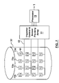
- FIG. 7 is a simplified schematic drawing of a Multiple-Impactor Multiple-Sensor (MIMS) inspection system according to yet another embodiment of the invention.
- MIMS Multiple-Impactor Multiple-Sensor
- a transient propagated stress wave such as a compressive (i.e. longitudinal, primary, etc.) stress wave
- a compressive stress wave is used to determine the condition of a refractory lining.
- the reflections of the stress wave are evaluated to identify the presence and position of defects such as, for example, cracks, delaminations and bubbles in the refractory lining in addition to the overall remaining thickness of the refractory lining.
- the transient propagated stress wave includes frequencies ranging from the acoustic (i.e. audible) to the ultrasonic (i.e.
- a stress wave generated according to an embodiment of the invention may have a frequency range of 100 Hz to 80 kHz. This range of frequencies can be advantageous in many scenarios since ultrasonic stress waves alone typically lack sufficient energy to pass through thick refractory linings and generally experience rapid attenuation through solid heterogeneous masses.
- some embodiments of the present invention provide a systematic way to include the affect that temperature has on the velocity of a compressive stress wave through a heated refractory material and/or accretions.
- the velocity of a stress wave, at each frequency and in a refractory material is not necessarily constant over a temperature range.
- a scaling factor ⁇ can be calculated for each refractory material to adjust for the presumed velocity of the stress wave through each refractory material.
- the scaling factor ⁇ for a particular refractory material is a function of the modulus of elasticity E and the temperature and/or temperature gradient through that refractory material.
- the scaling factor ⁇ is calculated as a function of the relative change in the modulus of elasticity E over a temperature range corresponding to the temperature gradient through a layer of one type of refractory material. As will be described in more detail below this is a significant departure from what is known in the art, since a change in the modulus of elasticity E and the corresponding affect on the velocity of a stress wave through a particular refractory material were previously assumed to be non-existent.
- the modulus of elasticity for a material E is a quantitative relationship between stress and strain in that material.
- metals e.g. steel, lead, copper, etc.
- This relationship between stress and strain is often quantified as the modulus of elasticity E, which is commonly calculated as a ratio of stress to strain.
- the change in the deformation behavior is due to the weakening of a metal lattice structure at higher temperatures that in turn allows metal atoms to flow more easily.
- the melting point temperature is reached and a solid metal changes to a liquid.
- the melting point is approximately 1500° C.
- Refractory materials have a very strong lattice structure and high temperatures do not generally cause a refractory material to melt and/or behave in a way that can be categorized as plastic. Refractory materials also tend to be far more brittle than metals. As a result, the melting and deformation characteristics of metals described above are not found in refractory materials. By contrast, refractory materials simply tend to break, crack and/or disintegrate into a powder while remaining in the elastic regime.
- the modulus of elasticity E of a refractory material does not change significantly as a function of temperature in a way that is comparable to the change observed in metals.
- the modulus of elasticity E for a particular refractory material is typically considered to be a constant. Seemingly negligible changes in a modulus of elasticity E were previously not considered to be of importance when considering properties of a refractory material in relation to the intended uses for that refractory material.
- a relative change in the modulus of elasticity E may have a significant impact on the velocity of a stress wave in the refractory material.
- a shock or impulse disturbance to a solid induces a number of linear and angular displacements within that solid.
- the applied shock or impulse disturbance generates various types of stress waves. Stress waves may be categorized as either body or surface waves. Body waves travel through a solid, whereas surface waves travel primarily along the surface of the solid.
- P-waves Primary-waves
- S-waves Secondary-waves
- S-waves induce particle motion in the same direction as the path of travel of the wave front. That is, as a P-wave passes through a solid, particles vibrate about an equilibrium position, in the same direction as the P-wave is traveling.
- P-waves also cause compression and rarefaction, but not rotation of a refractory material.
- S-waves induce particle motion perpendicular to the path of travel to the wave front. That is, as an S-wave travels through a body, particle displacement is perpendicular to the direction of propagation of the S-wave.
- S-waves also cause shearing and rotation, but no volume changes of a refractory material.
- P-waves and reflections of P-waves are evaluated to determine the condition of a refractory lining of an operating metallurgical furnace.
- P-waves are generally considered to be the fastest of the stress waves and are known to travel through solids, liquids, and gases. Accordingly, measurements relating to the thickness of a refractory lining and the presence and position of accretions and defects in the refractory lining can be determined using data collected about the propagation of P-waves through the walls of an operating metallurgical furnace irrespective of the state of the matter at any point within the walls.
- some embodiments of the invention provide a method by which the effect of temperature on P-wave velocity, through a refractory material included in a furnace wall, can be more accurately considered.
- the fundamental wave equation (1) is suitable to relate velocity V p of a P-wave to the frequency f and wavelength ⁇ of the P-wave.
- the velocity V p of a P-wave in a particular refractory material and the density ⁇ of the refractory material can be multiplied together to determine the acoustic impedance Z for that refractory material, as shown in equation (2).
- the acoustic impedance Z provides a value that is useful in estimating how much energy is reflected from an interface between two materials.
- V p f ⁇ (1)
- Z ⁇ V p (2)
- equations (1) and (2) produce inaccurate results stemming from assumptions made about the wavelength ⁇ and frequency f of a P-wave in a heated refractory material.
- the extremely high temperatures inside an operating furnace result in non-linear changes in the wavelength ⁇ and frequency f of a P-wave, which are not accurately observable or observable at all given the hostile working-environment the furnaces are included in.
- significant errors are encountered when using previously known methods of inspecting operating metallurgical furnaces.
- the velocity V p of a P-wave in a refractory material can also be determined from the density ⁇ and the modulus of elasticity E d of the refractory material.
- the velocity V p of a P-wave through an infinite isotropic elastic refractory solid, with homogeneous composition can be determined with equation (3).
- equation (4) provides the velocity V p of a P-wave through refractory rod-shaped structures, where the diameter of the rod is much smaller than the length (i.e. d ⁇ L).
- V p E d ⁇ ( 1 - ⁇ ) ( 1 + ⁇ ) ⁇ ( 1 - 2 ⁇ ⁇ ) ⁇ ⁇ ( 3 )
- V p E d ⁇ ( 4 )
- ⁇ Poisson's ratio
- ⁇ is again the density
- E d is Young's (dynamic) modulus of elasticity for the refractory material.
- equation (4) The velocity of a P-wave through a rod-shaped structure, as given by equation (4), will be less than the velocity of the P-wave through an infinite isotropic solid, as given by (3).
- equations (3) and (4) define respective upper and lower end points for a range of P-wave velocities in homogenous refractory solid structures that fall somewhere between the extremes of a infinite solid mass and a very skinny rod.
- equations (3) and (4) relate elasticity of a material to velocity, neither take into consideration the temperature of the material.
- Some embodiments of the invention provide a velocity scaling-factor ⁇ that can be used to correct the velocity of a P-wave in a refractory material in which the modulus of elasticity changes due to extreme heating.
- the velocity scaling-factor ⁇ is calculated as a function of the relative change in the modulus of elasticity E d over a temperature range corresponding to a temperature gradient through a layer of one type of refractory material. Accordingly, velocity equations (3) and (4) can be re-written as corrected equations (5) and (6), respectively.
- E d2 and E d1 correspond to the elasticity of the refractory material at respective first and second temperatures (e.g. on a hot face and cooler face, respectively, of a refractory brick), whereas E o corresponds to the elasticity used to first calculate the uncorrected velocity V p , which is likely the room temperature value of E d available from the manufacturers of refractory materials.
- the change in elasticity as a function of temperature is generally non-linear and not always easily characterized in an equation as simple as equation (7).
- advanced curve fitting techniques can be used to derive numbers for the integral, shown in equation (7), as required for each type of refractory material.
- each type of refractory material used in a furnace wall will have a corresponding velocity scaling-factor ⁇ .
- many manufacturers do not have accurate elasticity data for refractory materials at high temperatures, since elasticity in such materials is normally assumed to be relatively constant. Accordingly, in many cases testing has to be done to determine elasticity at elevated temperatures in the range of those found in metallurgical furnaces. The tests involve heating the refractory material and measuring either the static or dynamic modulus of elasticity.
- FIG. 1 shown is a cross-sectional drawing of a simplified example metallurgical furnace 30 .
- the metallurgical furnace 30 includes an outer steel shell 31 , a first layer of refractory bricks 33 and a second layer of refractory bricks 35 .
- a roof (not shown in FIG. 1 ) that includes an outer steel shell and an inner refractory lining or only a singular refractory layer.
- the first layer of refractory bricks 33 is closest to the steel shell 31 and is considered a safety layer.
- the second layer of refractory bricks 35 in direct contact with the molten material 100 , is considered a working layer.
- the bricks in a safety layer are typically less dense than the bricks in a working layer.
- the reverse may be true or the bricks may be of the same type in each layer.
- a safety layer is composed of a castable material (e.g. a mixture of sand, concrete, alumina and/or other materials), in contrast to bricks as described above.
- each of the first and second layers of refractory bricks 33 and 35 is partially dependent on the process the metallurgical furnace is involved in. Generally, the more aggressive the process the thicker the layers are. Thicknesses for refractory linings typically range from 600 mm to 1600 mm.
- molten material 100 e.g. molten iron ore
- the first and second layers of refractory bricks 33 and 35 have both been deteriorated to some degree.
- the second layer of refractory bricks 35 is significantly deteriorated and has a number of defects including accretions 41 , 43 and 45 , a delamination zone 47 , and an area of extreme wear 49 .
- the accretions 41 , 43 and 45 are composed of impurities that have settled out of the molten material 100 .
- Delamination e.g. delamination 47
- Delaminations near the steel shell 31 can be very dangerous, since the steel shell 31 may be exposed to the molten material 100 .
- Areas of extreme wear e.g. area 49 ) naturally occur over time as the working layer bricks are wasted away.
- the total thickness of a furnace wall at a point is the combination of the remaining portions of refractory brick layers at that point in addition to any accretion on the working layer of the refractory lining at that point plus the thickness of the outer shell. Since deterioration is difficult, if not impossible, to control and/or predict the thickness of the refractory lining is expected to be different at different points. However, at each point the same method can be used to evaluate the thickness of the refractory lining.
- a P-wave is generated by an impact applied to the steel shell 31 of the metallurgical furnace 30 .
- the P-wave travels through the steel shell 31 and through the refractory brick layers 33 and 35 .
- Reflections of the P-wave are created at material interfaces and most notably at the interface between the second layer of refractory bricks 35 and the molten material 100 , and the interfaces created by defects (e.g. cracks, delaminations, bubbles and the like).
- a velocity scaling-factor ⁇ is determined for each refractory material (e.g. for each refractory brick layer 33 and 35 ) included in the refractory lining. This method will be described in further detail below with reference to FIGS. 4 and 5 .
- the velocity scaling-factor ⁇ is calculated as a function of the relative change in the modulus of elasticity over a temperature gradient present in a layer of the refractory material.
- the temperature gradient includes only a single temperature because a particular refractory material heats evenly to the single temperature.
- the temperature gradient corresponds to a specific temperature gradient expected in another type of refractory material.
- FIGS. 2A and 2B graphically illustrate respective first and second examples of how elasticity in the corresponding refractory materials in layers 33 and 35 are temperature dependent.
- FIGS. 3 and 4 shown is a system for determining the condition of a refractory lining in a metallurgical furnace, as provided by a very specific embodiment of the invention.
- FIG. 3 includes the metallurgical furnace 30 and all of the defects and patterns of deterioration described above with reference to FIG. 1 . Accordingly, FIGS. 1 and 3 share common reference indicia for identical features common to both figures.
- the system shown in FIGS. 3 and 4 is a Single Impactor Single Sensor (SISS) system because it includes a single impactor 70 and a single sensor 72 .
- the impactor 70 and sensor 72 are placed adjacent to one another.
- the system also includes a processor 76 and an optional pre-amplifier (Pre-Amp) 74 .
- Pre-Amp pre-amplifier
- the SISS system also includes a suitable combination of associated structural elements, mechanical systems, hardware, firmware and software that is employed to support the function and operation of the SISS system.
- Such items may include, without limitation, a power supply, piping, vibration sensors, regulators, seals, insulators and electromechanical controllers.
- the senor 72 is a broadband vertical displacement transducer or a similar device suitable to operate as a stress wave sensor.
- accelerometers and like devices are also suitable for use as the sensor 72 .
- the senor 72 is coupled to provide a signal to the processor 76 through the optional Pre-Amp 74 .
- the sensor 72 is coupled directly to the processor 76 .
- the Pre-Amp 74 operates to amplify the sensor readings of the sensor 72 .
- the processor 76 operates to evaluate sensor readings received from the Pre-Amp 74 (or directly from the sensor 72 ) to determine the condition of the refractory lining under the sensor 72 .
- a measure of the total thickness T t of the furnace wall under the sensor 72 is the combined thickness of the outer steel shell 31 , the first and second refractory brick layers 33 and 35 , and the accretion 45 .
- the processor 76 includes a computer readable program code means embodied therein for determining a condition of a refractory lining.
- the computer readable program code means includes instructions for triggering the impactor 70 to generate a P-wave and evaluating reflections of the P-wave.
- the impactor 70 is used to generate a P-wave that is transmitted into the wall of the metallurgical furnace 30 by first striking a point on the outer steel shell 31 . That is, the impactor 70 is a device suitable to operate as a stress wave generator. In some embodiments, the impactor 70 is a spherical impactor. Spherical impactors generate simple, easy to analyze spherical P-waves in a broad range of frequencies. In alternative embodiments, P-waves can be generated manually with a mallet (or similar instrument), with controlled electric shocks and/or small explosions.
- the frequency range of a P-wave generated by the impactor can be controlled by adjusting at least one of a number of parameters, including, without limitation, the diameter of the contact point of a spherical impactor, the surface smoothness of the outer steel shell 31 , the input force and the contact time t c .
- a P-wave with a relatively high frequency range will be generated if the outer steel shell 31 is smooth, clean and struck with a relatively small-diameter impact source.
- the highest useful frequency component of a generated P-wave may be estimated from the contact time t c according equation (8).
- the contact time t c is the duration of time that the impactor 70 connects with the steel shell 31 .
- the contact time t c can be adjusted to control the generated range of frequencies in a P-wave. Having a relatively broad range of frequencies in a single P-wave is advantageous as wave energy at each frequency is attenuated to different degrees as a function of the materials through which the P-wave travels.
- an impact results in the generation of a semi-spherical P-wave 81 below the point of impact.
- Surface waves and S-waves are also generated, however, more of the energy is transmitted via the P-wave 81 directly away from the impactor 70 .
- the P-wave 81 propagates away from the impactor 70 until it encounters acoustic interfaces (boundaries) or fades away due to attenuation through the furnace.
- a P-wave encounters an acoustic interface, depending on the material properties of the acoustic interface, either the entire wave or part of the wave reflects back towards the source of impact. If a second material has significantly lower acoustic impedance than a first material from which a P-wave originates (e.g. refractory to gas or refractory to liquid interfaces), then a significant portion of the P-wave reflects back in the direction it started from. Such an interface is called a stress free interface. On the other hand, if the second material has significantly higher acoustic impedance than the first material, part of the P-wave reflects back and the other part continues to propagate into the second material.
- a small portion of the propagating P-wave in the second material refracts along the interface and another small portion of the propagating P-wave is converted into waveforms (e.g. surface waves and S-waves). Reflections bounce back and forth between acoustic interfaces, naturally attenuated as they travel through a material, until the energy more-or-less completely fades away. If the two materials have similar acoustic impedances then the amount of the reflection is small and natural attenuation from the materials tends to fade the reflection out of existence before the reflection reaches the original impact/sensor point.
- waveforms e.g. surface waves and S-waves
- Each interface between adjacent layers can be considered a respective acoustic interface, since each layer likely has an acoustic-impedance that is different from those of the layers adjacent to it.
- reflections from interfaces between refractory layers e.g. 33 and 35
- the propagating P-wave 81 encounters an acoustic interface, it goes through reflection, refraction, diffraction and mode conversion.
- effects stemming from refraction, diffraction and mode conversion are not given significant consideration, whereas reflections are considered in greater detail.
- the sensor 72 is arranged to sense reflections, indicated for example by a single semi-spherical P-wave reflection 83 in FIG. 4 , as they arrive back to the impact source.
- the reflection arrivals are almost periodic and relate to the velocity of the P-wave 81 in the refractory lining and the total path length of the P-wave 81 (and reflection 83 ), which is twice the total thickness T t of the furnace wall.
- the duration between two successive reflection arrivals is an estimate of how long the P-wave 81 and a corresponding reflection 83 took to travel through a corresponding layer in the furnace wall.
- equation (9) provides an estimate of a time during which a P-wave travels in a given refractory layer n.
- T n is the thickness of a particular refractory layer n
- V pn is the uncorrected velocity
- t pn is one specific duration of time between reflection arrivals.
- the time t pn can be considered as the period between reflections 83 .
- equation (9) can be written in terms of frequency of reflections as shown in equation (10).
- the reflections 83 taken collectively, form a time domain acousto-ultrasonic echo response of the furnace wall to the P-wave 81 generated by the impactor 70 .
- the time domain acousto-ultrasonic echo response can be converted into corresponding a frequency domain acousto-ultrasonic echo response using a Fast Fourier Transform (FFT) method or another (and likely less efficient) digital signaling processing technique by the processor 76 .
- the processor 76 has access to a computer readable medium having instructions for carrying out an FFT method or another digital signal processing method for converting between the time and frequency domains.
- the frequency domain acousto-ultrasonic echo response shows the effect that successive reflection arrivals have on the surface of the outer steel shell 31 .
- equations (9) and (10) can be used, in accordance with a very specific embodiment of the invention, the velocity V p of the P-wave 81 and corresponding reflection 83 in each refractory material is corrected by applying the aforementioned velocity scaling factor ⁇ n , for each corresponding refractory material n.
- the wave speed generated by the impact source is an indirect measurement of the P-wave speed.
- An impact source causes multiple reflections of the P-waves causing excitation of a particular mode of vibration.
- This mode of vibration is called thickness mode of vibration and results in alternating expansions and contractions across the thickness of the object.
- Numerous finite element and laboratory experimentations, covering a wide range of shapes and dimensions for the solids were used to determine the first mode of vibration generated by an impactor.
- This first mode of vibration or fundamental frequency affects the P-wave speed and is called ⁇ . That is, a second geometry-dependent velocity scaling-factor ⁇ n may also optionally be applied for each refractory material n in order to improve the accuracy of the thickness and/or defect identification measurements obtained.
- a second velocity scaling-factor ⁇ may be determined as a function of the relative dimensional ratio of a typical refractory brick within each of the refractory brick layers 33 and 35 .
- ⁇ is 0.96 for length-to-width ratios over 2.0 and ranges between 0.90 and 0.96 for length-to-width ratios between 1.0 and 2.0.
- the precise values for ⁇ can be determined on bricks at room temperature. If a refractory layer includes bricks of different shapes, then each shape should be considered.
- the processor has access to a computer readable medium having instructions for determining the uncorrected velocities and scaling factors for each refractory material.
- the thickness of a refractory lining including only one type of refractory material can be calculated according to equation (11) as follows.
- the thickness equation becomes more complex and is easier to solve in the frequency domain. Since each refractory layer contains bricks of different composition and thickness, the P-wave velocity through each layer can now be taken into consideration in the overall assessment of the furnace wall. Subsequently, equation (11) is changed and takes the form of equation (12).
- f t 1 2 ⁇ T 1 ⁇ 1 ⁇ ⁇ 1 ⁇ V p ⁇ ⁇ 1 + 2 ⁇ T 2 ⁇ 2 ⁇ ⁇ 2 ⁇ V p ⁇ ⁇ 2 + 2 ⁇ T 3 ⁇ 3 ⁇ ⁇ 3 ⁇ V p ⁇ ⁇ 3 + ... ( 12 )
- V p1 is the P-wave velocity in the material of layer 1
- T 1 is the thickness of layer 1
- V p2 is the P-wave velocity in the material of layer 2
- T 2 is the thickness of layer 2 , and so forth.
- FIG. 5 a flow chart illustrating one very specific example method according to an embodiment of the invention is provided.
- a number of steps in FIG. 5 are collectively assigned a prefex “B” because these particular steps have been provided to illustratively describe, in simplified discrete steps, what is happening to a P-wave as it travels through a furnace wall. These steps generally cannot be controlled after the P-wave is created.
- a prefex “B” because these particular steps have been provided to illustratively describe, in simplified discrete steps, what is happening to a P-wave as it travels through a furnace wall. These steps generally cannot be controlled after the P-wave is created.
- Those skilled in the art will appreciate that an actual sequence of events relating to a propagating P-wave is somewhat more complex.
- the impactor 70 is triggered to generate the P-wave 81 on the outer surface of the outer steel shell 31 . Consequently, at step B 5 - 2 the P-wave 81 propagates through the outer steel shell 31 . At step B 5 - 3 , the P-wave reaches an acoustic interface that may be representative of the first refractory layer of bricks 33 , the molten material 100 or a defect as described above.
- step B 5 - 4 if the material at the acoustic interface is the molten material (no path, step B 5 - 4 ), then most of the P-wave 81 is reflected backwards towards the sensor 72 . The rest is lost into the molten material 100 .
- the material at the acoustic interface is a solid (e.g. the first refractory layer of bricks 33 ), then (yes path, step B 5 - 4 ) a portion of the P-wave 81 continues to propagate away from the impactor 70 at step B 5 - 6 and another portion of the P-wave 81 reflects back towards the impactor 70 at step B 5 - 7 .
- step B 5 - 6 the P-wave 81 continues to repeat through steps B 5 - 3 , B 5 - 4 and so on until the wave energy finally completely fades away.
- the reflections 83 produced at steps B 5 - 5 and B 5 - 7 eventually reach the outer steel shell 31 , at step B 5 - 8 , after reflections, refractions, diffractions, and mode conversions of their own.
- the sensor 72 senses the reflections 83 as they arrive over time and the processor 76 records the arrival time and magnitude of each reflection. This data forms the time domain acousto-ultrasonic echo response of the furnace wall to the P-wave 81 .
- the processor 76 converts the time domain acousto-ultrasonic echo response to a frequency domain acousto-ultrasonic echo response at step 5 - 10 .
- the frequency domain acousto-ultrasonic echo response is evaluated, as in equations (9) and (12) to determine the condition of the refractory lining, taking into consideration the uncorrected velocities and scaling factors described above, which can be calculated a priori.
- FIG. 6 A simplified illustration showing a Single-Impactor Multiple-Sensor (SIMS) non-destructive and non-invasive inspection system according to another embodiment is provided in FIG. 6 .
- SIMS Single-Impactor Multiple-Sensor
- FIG. 6 also includes the metallurgical furnace 30 and all of the defects and patterns of deterioration described above with reference to FIG. 1 . Accordingly, FIGS. 1 , 3 and 6 share common reference indicia for identical features common to all three figures.
- the SIMS system shown in FIG. 6 includes the single impactor 70 as described for the SISS system in FIG. 3 .
- the SIMS system includes two sensors 72 a,b and two corresponding optional Pre-Amps 74 a,b . That is, the two sensors 72 a,b are optionally coupled to the processor 76 through the two corresponding Pre-Amps 74 a,b , respectively
- the sensors 72 a,b are placed adjacent to the impactor 70 , and, in operation measurements obtained from the two sensors 72 a,b are averaged, correlated and/or integrated together. Again, velocity scaling-factors are advantageously employed as described above.
- the processor may have access to a computer readable program code means having instructions for combining the measurements from the two sensors 72 a,b.
- FIG. 7 a simplified schematic drawing of a Multiple-Impactor Multiple-Sensor (MIMS) non-destructive and non-invasive inspection system is provided in FIG. 7 in combination with a metallurgical furnace 32 .
- the MIMS shown in FIG. 7 , includes a number of sensor-impactor pairs, indicated for example by 73 a , 73 b , 73 c and 74 d , that are arranged around the surface of the metallurgical furnace 32 .
- the MIMS system also includes an impactor control and sensor Pre-Amp array 77 and a processor 78 . Each of the sensor-impactor pairs is coupled to the processor 78 via the impactor control and sensor Pre-Amp array 77 .
- the sensor-impactor pair 73 d is coupled to the impactor control and sensor Pre-Amp array 77 by a I/O line 61 that branches from a I/O bus 63 connected to the impactor control and sensor Pre-Amp array 77 .
- individual impactors may be triggered one at a time, in groups or all together.
- Each impactor can be arranged and triggered to generate a respective P-wave that has a specific range of frequencies that may or may not be different from the P-waves generated by other impactors included in the MIMS system.
- the impactor control and sensor Pre-Amp array 77 and/or processor 78 may have access to a computer program readable code means having instructions for combining the measurements
- the individual sensors may be used to collect P-wave data from the impactors they are paired with and/or one or more impactors in the MIMS system. Accordingly, reflection measurements collected from one or more of the sensors can be averaged, correlated and/or integrated together. Again, velocity scaling-factors are advantageously employed as described above.
- the processor 78 may have access to a computer program readable code means having instructions for combining the measurements.
Abstract
Description
V p =f×λ (1)
Z=ρ×V p (2)
In equations (3) and (4), ν is Poisson's ratio, ρ is again the density and Ed is Young's (dynamic) modulus of elasticity for the refractory material.
The terms Ed2 and Ed1 correspond to the elasticity of the refractory material at respective first and second temperatures (e.g. on a hot face and cooler face, respectively, of a refractory brick), whereas Eo corresponds to the elasticity used to first calculate the uncorrected velocity Vp, which is likely the room temperature value of Ed available from the manufacturers of refractory materials.
The contact time tc is the duration of time that the impactor 70 connects with the
The term Tn is the thickness of a particular refractory layer n, Vpn is the uncorrected velocity, and tpn is one specific duration of time between reflection arrivals. The time tpn can be considered as the period between
where ft is the P-wave thickness frequency of the refractory layers, Vp1 is the P-wave velocity in the material of layer 1, T1 is the thickness of layer 1, Vp2 is the P-wave velocity in the material of layer 2, T2 is the thickness of layer 2, and so forth.
Claims (16)
Priority Applications (1)
| Application Number | Priority Date | Filing Date | Title |
|---|---|---|---|
| US11/962,896 US7665362B2 (en) | 2005-02-22 | 2007-12-21 | Systems, methods and apparatus for non-disruptive and non-destructive inspection of metallurgical furnaces and similar vessels |
Applications Claiming Priority (2)
| Application Number | Priority Date | Filing Date | Title |
|---|---|---|---|
| US11/061,630 US20060186585A1 (en) | 2005-02-22 | 2005-02-22 | Systems, methods and apparatus for non-disruptive and non-destructive inspection of metallurgical furnaces and similar vessels |
| US11/962,896 US7665362B2 (en) | 2005-02-22 | 2007-12-21 | Systems, methods and apparatus for non-disruptive and non-destructive inspection of metallurgical furnaces and similar vessels |
Related Parent Applications (1)
| Application Number | Title | Priority Date | Filing Date |
|---|---|---|---|
| US11/061,630 Division US20060186585A1 (en) | 2005-02-22 | 2005-02-22 | Systems, methods and apparatus for non-disruptive and non-destructive inspection of metallurgical furnaces and similar vessels |
Publications (2)
| Publication Number | Publication Date |
|---|---|
| US20080092658A1 US20080092658A1 (en) | 2008-04-24 |
| US7665362B2 true US7665362B2 (en) | 2010-02-23 |
Family
ID=36911842
Family Applications (2)
| Application Number | Title | Priority Date | Filing Date |
|---|---|---|---|
| US11/061,630 Abandoned US20060186585A1 (en) | 2005-02-22 | 2005-02-22 | Systems, methods and apparatus for non-disruptive and non-destructive inspection of metallurgical furnaces and similar vessels |
| US11/962,896 Active 2025-05-20 US7665362B2 (en) | 2005-02-22 | 2007-12-21 | Systems, methods and apparatus for non-disruptive and non-destructive inspection of metallurgical furnaces and similar vessels |
Family Applications Before (1)
| Application Number | Title | Priority Date | Filing Date |
|---|---|---|---|
| US11/061,630 Abandoned US20060186585A1 (en) | 2005-02-22 | 2005-02-22 | Systems, methods and apparatus for non-disruptive and non-destructive inspection of metallurgical furnaces and similar vessels |
Country Status (5)
| Country | Link |
|---|---|
| US (2) | US20060186585A1 (en) |
| CN (1) | CN100501323C (en) |
| AU (1) | AU2005203598B2 (en) |
| CA (1) | CA2515477C (en) |
| ZA (1) | ZA200506661B (en) |
Cited By (4)
| Publication number | Priority date | Publication date | Assignee | Title |
|---|---|---|---|---|
| WO2012159208A1 (en) * | 2011-05-20 | 2012-11-29 | Hatch Ltd. | Furnace structural integrity monitoring systems and methods |
| US9194769B1 (en) * | 2013-01-23 | 2015-11-24 | The Boeing Company | Systems and methods for environmental testing and evaluation of non-destructive inspection sensors |
| US20160313234A1 (en) * | 2013-12-28 | 2016-10-27 | Sumco Corporation | Vitreous silica crucible and distortion-measuring apparatus for the same |
| US10935320B2 (en) | 2013-04-12 | 2021-03-02 | Refractory Intellectual Property Gmbh & Co. Kg | Method for determining the state of a refractory lining of a metallurgical vessel for molten metal in particular |
Families Citing this family (17)
| Publication number | Priority date | Publication date | Assignee | Title |
|---|---|---|---|---|
| JP4980245B2 (en) * | 2005-01-17 | 2012-07-18 | ピー−レスポンス アイピー プロプライエタリー リミテッド | Non-destructive testing of process vessel linings |
| US20060186585A1 (en) * | 2005-02-22 | 2006-08-24 | Afshin Sadri | Systems, methods and apparatus for non-disruptive and non-destructive inspection of metallurgical furnaces and similar vessels |
| CA2695464C (en) * | 2007-09-28 | 2015-12-22 | Hatch Ltd. | System and method for the acoustic monitoring of tapblocks and similar elements |
| US9177371B2 (en) * | 2008-06-09 | 2015-11-03 | Siemens Energy, Inc. | Non-destructive examination data visualization and analysis |
| CN101614533B (en) * | 2008-06-26 | 2012-01-11 | 中国科学院金属研究所 | Method and instrument capable of accurately measuring thickness of ultrathin workpieces |
| CN102830620A (en) * | 2012-08-29 | 2012-12-19 | 中钢集团洛阳耐火材料研究院有限公司 | Method for controlling and optimizing baking system of fire-resistant preformed unit |
| US9881510B2 (en) * | 2012-12-21 | 2018-01-30 | General Electric Company | Testing system and method |
| US9279773B2 (en) * | 2014-07-18 | 2016-03-08 | Process Metrix | Crack detection and measurement in a metallurgical vessels |
| CN104180780B (en) * | 2014-09-05 | 2017-01-25 | 哈尔滨工业大学 | High-temperature liquid container wall thickness monitoring system and method based on infrared thermal images |
| KR101714928B1 (en) | 2015-12-22 | 2017-03-10 | 주식회사 포스코 | Apparatus and method for measuring thickness of refractory in blast furnace hearth |
| CN106644704B (en) * | 2017-03-09 | 2019-02-22 | 中国工程物理研究院核物理与化学研究所 | A kind of test method of material microdeformation |
| CN109254077B (en) * | 2017-07-14 | 2021-04-06 | 财团法人工业技术研究院 | Degradation detection method of structural member |
| WO2019186256A1 (en) * | 2018-03-30 | 2019-10-03 | Tata Steel Limited | Method of detecting crack propagation in wall of a metallurgical furnace and a detection unit |
| CN110564905B (en) * | 2019-10-08 | 2020-10-09 | 中南大学 | Signal processing method and system for blast furnace lining impact echo detection |
| WO2021105758A1 (en) * | 2019-11-29 | 2021-06-03 | Arcelormittal | System and method for estimating both thickness and wear state of refractory material of a metallurgical furnace |
| CN113514014B (en) * | 2021-04-15 | 2023-03-17 | 鞍钢股份有限公司 | Device and method for measuring thickness of blast furnace wall by correcting stress wave method |
| WO2023208567A1 (en) * | 2022-04-26 | 2023-11-02 | Tata Steel Ijmuiden B.V. | Method and system for the end-of-cast control in a blast furnace operation |
Citations (20)
| Publication number | Priority date | Publication date | Assignee | Title |
|---|---|---|---|---|
| US2450159A (en) | 1944-08-14 | 1948-09-28 | Allis Chalmers Mfg Co | Control system |
| US2632862A (en) | 1950-05-02 | 1953-03-24 | Westinghouse Electric Corp | Regulating system |
| US3767832A (en) | 1972-08-17 | 1973-10-23 | G Bennett | Automatic electrode control |
| US4207771A (en) * | 1979-03-02 | 1980-06-17 | Western Electric Company, Inc. | Method and apparatus for monitoring cracking using stress wave emission techniques |
| US4358953A (en) | 1980-08-28 | 1982-11-16 | Kobe Steel, Ltd. | Method of monitoring the wear of refractory walls of a blast furnace and temperature probe used for the method |
| US4494408A (en) * | 1982-07-27 | 1985-01-22 | Ford Aerospace & Communications Corporation | Method and apparatus for non-destructive testing of composite materials |
| US4607374A (en) | 1983-12-23 | 1986-08-19 | Daidotokushuko Kabushikikaisha | Method for controlling arc furnace |
| US4872345A (en) | 1988-03-30 | 1989-10-10 | Shell Oil Company | Measuring wall erosion |
| EP0429774A1 (en) | 1989-11-30 | 1991-06-05 | DANIELI & C. OFFICINE MECCANICHE S.p.A. | Direct-arc electric furnace fed with controlled current and method to feed a direct-arc furnace with controlled current |
| US5040419A (en) | 1990-01-19 | 1991-08-20 | Alcan International Limited | Methods and apparatus for non-destructive testing of materials using longitudinal compression waves |
| US5101162A (en) * | 1990-02-16 | 1992-03-31 | Rolls-Royce Plc | Method and apparatus for testing the response of a stress wave sensor |
| US5890805A (en) | 1997-09-26 | 1999-04-06 | Usx Corporation | Method for monitoring the wear and extending the life of blast furnace refractory lining |
| US5983701A (en) | 1997-06-13 | 1999-11-16 | The Royal Institution For The Advancement Of Learning | Non-destructive evaluation of geological material structures |
| US20030145659A1 (en) * | 2001-12-10 | 2003-08-07 | Moe Momayez | Remote structural material evaluation apparatus |
| CA2460901A1 (en) | 2003-03-13 | 2004-09-13 | Andec Manufacturing Ltd. | System and method for inspecting an industrial furnace or the like |
| US6792358B2 (en) | 2002-05-13 | 2004-09-14 | Luis Paredes Rojas | System for a non-invasive online continuous measurement of phrase levels in converters or pyrometallurgical furnaces |
| CA2437323A1 (en) | 2003-08-14 | 2005-02-14 | Claude Allaire | Apparatus for the elastic properties measurement of materials and method therefor |
| US20060186585A1 (en) | 2005-02-22 | 2006-08-24 | Afshin Sadri | Systems, methods and apparatus for non-disruptive and non-destructive inspection of metallurgical furnaces and similar vessels |
| US7327637B2 (en) * | 2005-02-23 | 2008-02-05 | Massachusetts Institute Of Technology | Acoustic pulse actuator |
| US7458266B2 (en) * | 2004-09-27 | 2008-12-02 | Samsung Electronics Co. Ltd. | Method and apparatus for detecting a load change upon a structure and analyzing characteristics of resulting damage |
Family Cites Families (5)
| Publication number | Priority date | Publication date | Assignee | Title |
|---|---|---|---|---|
| NL183317C (en) * | 1982-06-03 | 1988-09-16 | Hoogovens Groep Bv | MAIN OVEN WALL. |
| US4890496A (en) * | 1988-09-07 | 1990-01-02 | Electric Power Research Institute | Method and means for detection of hydrogen attack by ultrasonic wave velocity measurements |
| JPH09211277A (en) * | 1996-01-31 | 1997-08-15 | Asahi Optical Co Ltd | Optical imaging device |
| US20030145639A1 (en) * | 2001-04-12 | 2003-08-07 | Secretary Of Army | Efficient fertilizer and enzyme-assisted method of production |
| US6860268B2 (en) * | 2002-02-06 | 2005-03-01 | Shelly Bohn | Pediatric ventilation mask and headgear system |
-
2005
- 2005-02-22 US US11/061,630 patent/US20060186585A1/en not_active Abandoned
- 2005-08-09 CA CA2515477A patent/CA2515477C/en active Active
- 2005-08-12 AU AU2005203598A patent/AU2005203598B2/en active Active
- 2005-08-19 ZA ZA200506661A patent/ZA200506661B/en unknown
- 2005-09-22 CN CNB2005101064092A patent/CN100501323C/en active Active
-
2007
- 2007-12-21 US US11/962,896 patent/US7665362B2/en active Active
Patent Citations (22)
| Publication number | Priority date | Publication date | Assignee | Title |
|---|---|---|---|---|
| US2450159A (en) | 1944-08-14 | 1948-09-28 | Allis Chalmers Mfg Co | Control system |
| US2632862A (en) | 1950-05-02 | 1953-03-24 | Westinghouse Electric Corp | Regulating system |
| US3767832A (en) | 1972-08-17 | 1973-10-23 | G Bennett | Automatic electrode control |
| US4207771A (en) * | 1979-03-02 | 1980-06-17 | Western Electric Company, Inc. | Method and apparatus for monitoring cracking using stress wave emission techniques |
| US4358953A (en) | 1980-08-28 | 1982-11-16 | Kobe Steel, Ltd. | Method of monitoring the wear of refractory walls of a blast furnace and temperature probe used for the method |
| US4494408A (en) * | 1982-07-27 | 1985-01-22 | Ford Aerospace & Communications Corporation | Method and apparatus for non-destructive testing of composite materials |
| US4607374A (en) | 1983-12-23 | 1986-08-19 | Daidotokushuko Kabushikikaisha | Method for controlling arc furnace |
| US4872345A (en) | 1988-03-30 | 1989-10-10 | Shell Oil Company | Measuring wall erosion |
| EP0429774A1 (en) | 1989-11-30 | 1991-06-05 | DANIELI & C. OFFICINE MECCANICHE S.p.A. | Direct-arc electric furnace fed with controlled current and method to feed a direct-arc furnace with controlled current |
| US5040419A (en) | 1990-01-19 | 1991-08-20 | Alcan International Limited | Methods and apparatus for non-destructive testing of materials using longitudinal compression waves |
| US5101162A (en) * | 1990-02-16 | 1992-03-31 | Rolls-Royce Plc | Method and apparatus for testing the response of a stress wave sensor |
| US5983701A (en) | 1997-06-13 | 1999-11-16 | The Royal Institution For The Advancement Of Learning | Non-destructive evaluation of geological material structures |
| US5890805A (en) | 1997-09-26 | 1999-04-06 | Usx Corporation | Method for monitoring the wear and extending the life of blast furnace refractory lining |
| US20030145659A1 (en) * | 2001-12-10 | 2003-08-07 | Moe Momayez | Remote structural material evaluation apparatus |
| US6792358B2 (en) | 2002-05-13 | 2004-09-14 | Luis Paredes Rojas | System for a non-invasive online continuous measurement of phrase levels in converters or pyrometallurgical furnaces |
| CA2460901A1 (en) | 2003-03-13 | 2004-09-13 | Andec Manufacturing Ltd. | System and method for inspecting an industrial furnace or the like |
| US20040177692A1 (en) | 2003-03-13 | 2004-09-16 | Andec Manufacturing Ltd. | System and method for inspecting an industrial furnace or the like |
| US7174787B2 (en) * | 2003-03-13 | 2007-02-13 | Andec Manufacturing Ltd. | System and method for inspecting an industrial furnace or the like |
| CA2437323A1 (en) | 2003-08-14 | 2005-02-14 | Claude Allaire | Apparatus for the elastic properties measurement of materials and method therefor |
| US7458266B2 (en) * | 2004-09-27 | 2008-12-02 | Samsung Electronics Co. Ltd. | Method and apparatus for detecting a load change upon a structure and analyzing characteristics of resulting damage |
| US20060186585A1 (en) | 2005-02-22 | 2006-08-24 | Afshin Sadri | Systems, methods and apparatus for non-disruptive and non-destructive inspection of metallurgical furnaces and similar vessels |
| US7327637B2 (en) * | 2005-02-23 | 2008-02-05 | Massachusetts Institute Of Technology | Acoustic pulse actuator |
Cited By (8)
| Publication number | Priority date | Publication date | Assignee | Title |
|---|---|---|---|---|
| WO2012159208A1 (en) * | 2011-05-20 | 2012-11-29 | Hatch Ltd. | Furnace structural integrity monitoring systems and methods |
| AU2012260392B2 (en) * | 2011-05-20 | 2015-03-12 | Hatch Ltd. | Furnace structural integrity monitoring systems and methods |
| US9791416B2 (en) | 2011-05-20 | 2017-10-17 | Hatch Ltd. | Furnace structural integrity monitoring systems and methods |
| US9194769B1 (en) * | 2013-01-23 | 2015-11-24 | The Boeing Company | Systems and methods for environmental testing and evaluation of non-destructive inspection sensors |
| US10935320B2 (en) | 2013-04-12 | 2021-03-02 | Refractory Intellectual Property Gmbh & Co. Kg | Method for determining the state of a refractory lining of a metallurgical vessel for molten metal in particular |
| US20160313234A1 (en) * | 2013-12-28 | 2016-10-27 | Sumco Corporation | Vitreous silica crucible and distortion-measuring apparatus for the same |
| US9816917B2 (en) * | 2013-12-28 | 2017-11-14 | Sumco Corporation | Vitreous silica crucible and distortion-measuring apparatus for the same |
| US10024784B2 (en) | 2013-12-28 | 2018-07-17 | Sumco Corporation | Vitreous silica crucible and evaluation method of the same |
Also Published As
| Publication number | Publication date |
|---|---|
| AU2005203598A1 (en) | 2006-09-07 |
| CN1825056A (en) | 2006-08-30 |
| CA2515477A1 (en) | 2006-08-22 |
| AU2005203598B2 (en) | 2009-02-12 |
| CN100501323C (en) | 2009-06-17 |
| ZA200506661B (en) | 2006-04-26 |
| CA2515477C (en) | 2014-02-18 |
| US20080092658A1 (en) | 2008-04-24 |
| US20060186585A1 (en) | 2006-08-24 |
Similar Documents
| Publication | Publication Date | Title |
|---|---|---|
| US7665362B2 (en) | Systems, methods and apparatus for non-disruptive and non-destructive inspection of metallurgical furnaces and similar vessels | |
| US9212956B2 (en) | Ultrasonic temperature measurement device | |
| Kumar et al. | Recent trends in industrial and other engineering applications of non destructive testing: a review | |
| Placko | Advanced ultrasonic methods for material and structure inspection | |
| EP1893972B1 (en) | Systems, methods and apparatus for non-disruptive and non-destructive inspection of metallurgical furnaces and similar vessels | |
| Ohtsu et al. | Principles of the acoustic emission (AE) method and signal processing | |
| Javadi et al. | Ultrasonic stress evaluation through thickness of a stainless steel pressure vessel | |
| US7174787B2 (en) | System and method for inspecting an industrial furnace or the like | |
| JP2010038696A (en) | Non-destructive evaluation method of degree of metal fatigue damage and ultrasonic metal fatigue damage degree measuring instrument | |
| JP3379386B2 (en) | Refractory wear evaluation method and apparatus, and refractory management method and apparatus | |
| Wang et al. | Inspecting the current thickness of a refractory wall inside an operational blast furnace using the impact echo method | |
| Sgalla et al. | A device for measuring the velocity of ultrasonic waves: An application to stress analysis | |
| RU2529332C2 (en) | Method to determine topography of metallurgical facility lining layers | |
| Sadri et al. | Refractory wear and lining profile determination in operating electric furnaces using stress wave non-destructive testing (NDT) | |
| Sadri et al. | Non-destructive testing (NDT) and inspection of the blast furnace refractory lining by stress wave propagation technique | |
| Myers et al. | Heat flux determination from ultrasonic pulse measurements | |
| RU2305134C1 (en) | Method of determining topography of metallurgical assembly lining layers | |
| PERIYANNAN et al. | Elastic Moduli Measurements at Elevated Temperatures using Ultrasonic Waveguide Embodiments | |
| RU2451932C1 (en) | Method of measuring corrosion of main pipelines | |
| RU2326320C1 (en) | Method of determining topography of metallurgical facility lining layers | |
| JP2005010139A (en) | Residual thickness measuring method and device for furnace refractory using elastic wave | |
| Sadri et al. | Monitoring deterioration of waffle cooler thickness at Polokwane Smelter | |
| Sadri et al. | Implementing Risk-Based Inspection (RBI) and Life Cycle Monitoring into Refractory Lining Management of Pyrometallurgical Furnaces | |
| JP5272159B2 (en) | Mold nondestructive inspection method and apparatus | |
| Sadri et al. | New and innovative non-destructive testing (NDT) techniques for inspection and monitoring of metal smelting furnaces |
Legal Events
| Date | Code | Title | Description |
|---|---|---|---|
| AS | Assignment |
Owner name: HATCH LTD., CANADA Free format text: ASSIGNMENT OF ASSIGNORS INTEREST;ASSIGNOR:SADRI, AFSHIN;REEL/FRAME:020717/0223 Effective date: 20051007 Owner name: HATCH LTD.,CANADA Free format text: ASSIGNMENT OF ASSIGNORS INTEREST;ASSIGNOR:SADRI, AFSHIN;REEL/FRAME:020717/0223 Effective date: 20051007 |
|
| XAS | Not any more in us assignment database |
Free format text: ASSIGNMENT OF ASSIGNORS INTEREST;ASSIGNOR:SADRI, AFSHIN;REEL/FRAME:020284/0137 |
|
| STCF | Information on status: patent grant |
Free format text: PATENTED CASE |
|
| FEPP | Fee payment procedure |
Free format text: PAYOR NUMBER ASSIGNED (ORIGINAL EVENT CODE: ASPN); ENTITY STATUS OF PATENT OWNER: LARGE ENTITY |
|
| FPAY | Fee payment |
Year of fee payment: 4 |
|
| FPAY | Fee payment |
Year of fee payment: 8 |
|
| MAFP | Maintenance fee payment |
Free format text: PAYMENT OF MAINTENANCE FEE, 12TH YEAR, LARGE ENTITY (ORIGINAL EVENT CODE: M1553); ENTITY STATUS OF PATENT OWNER: LARGE ENTITY Year of fee payment: 12 |