US7673223B2 - Node processors for use in parity check decoders - Google Patents
Node processors for use in parity check decoders Download PDFInfo
- Publication number
- US7673223B2 US7673223B2 US11/178,951 US17895105A US7673223B2 US 7673223 B2 US7673223 B2 US 7673223B2 US 17895105 A US17895105 A US 17895105A US 7673223 B2 US7673223 B2 US 7673223B2
- Authority
- US
- United States
- Prior art keywords
- node
- message
- variable
- value
- constraint
- Prior art date
- Legal status (The legal status is an assumption and is not a legal conclusion. Google has not performed a legal analysis and makes no representation as to the accuracy of the status listed.)
- Expired - Fee Related, expires
Links
Images


Classifications
-
- G—PHYSICS
- G06—COMPUTING; CALCULATING OR COUNTING
- G06N—COMPUTING ARRANGEMENTS BASED ON SPECIFIC COMPUTATIONAL MODELS
- G06N3/00—Computing arrangements based on biological models
- G06N3/02—Neural networks
-
- H—ELECTRICITY
- H03—ELECTRONIC CIRCUITRY
- H03M—CODING; DECODING; CODE CONVERSION IN GENERAL
- H03M13/00—Coding, decoding or code conversion, for error detection or error correction; Coding theory basic assumptions; Coding bounds; Error probability evaluation methods; Channel models; Simulation or testing of codes
- H03M13/03—Error detection or forward error correction by redundancy in data representation, i.e. code words containing more digits than the source words
- H03M13/05—Error detection or forward error correction by redundancy in data representation, i.e. code words containing more digits than the source words using block codes, i.e. a predetermined number of check bits joined to a predetermined number of information bits
- H03M13/11—Error detection or forward error correction by redundancy in data representation, i.e. code words containing more digits than the source words using block codes, i.e. a predetermined number of check bits joined to a predetermined number of information bits using multiple parity bits
- H03M13/1102—Codes on graphs and decoding on graphs, e.g. low-density parity check [LDPC] codes
- H03M13/1105—Decoding
- H03M13/1111—Soft-decision decoding, e.g. by means of message passing or belief propagation algorithms
- H03M13/1117—Soft-decision decoding, e.g. by means of message passing or belief propagation algorithms using approximations for check node processing, e.g. an outgoing message is depending on the signs and the minimum over the magnitudes of all incoming messages according to the min-sum rule
- H03M13/112—Soft-decision decoding, e.g. by means of message passing or belief propagation algorithms using approximations for check node processing, e.g. an outgoing message is depending on the signs and the minimum over the magnitudes of all incoming messages according to the min-sum rule with correction functions for the min-sum rule, e.g. using an offset or a scaling factor
-
- H—ELECTRICITY
- H03—ELECTRONIC CIRCUITRY
- H03M—CODING; DECODING; CODE CONVERSION IN GENERAL
- H03M13/00—Coding, decoding or code conversion, for error detection or error correction; Coding theory basic assumptions; Coding bounds; Error probability evaluation methods; Channel models; Simulation or testing of codes
- H03M13/03—Error detection or forward error correction by redundancy in data representation, i.e. code words containing more digits than the source words
- H03M13/05—Error detection or forward error correction by redundancy in data representation, i.e. code words containing more digits than the source words using block codes, i.e. a predetermined number of check bits joined to a predetermined number of information bits
- H03M13/11—Error detection or forward error correction by redundancy in data representation, i.e. code words containing more digits than the source words using block codes, i.e. a predetermined number of check bits joined to a predetermined number of information bits using multiple parity bits
- H03M13/1102—Codes on graphs and decoding on graphs, e.g. low-density parity check [LDPC] codes
- H03M13/1105—Decoding
- H03M13/1111—Soft-decision decoding, e.g. by means of message passing or belief propagation algorithms
- H03M13/1125—Soft-decision decoding, e.g. by means of message passing or belief propagation algorithms using different domains for check node and bit node processing, wherein the different domains include probabilities, likelihood ratios, likelihood differences, log-likelihood ratios or log-likelihood difference pairs
-
- H—ELECTRICITY
- H03—ELECTRONIC CIRCUITRY
- H03M—CODING; DECODING; CODE CONVERSION IN GENERAL
- H03M13/00—Coding, decoding or code conversion, for error detection or error correction; Coding theory basic assumptions; Coding bounds; Error probability evaluation methods; Channel models; Simulation or testing of codes
- H03M13/03—Error detection or forward error correction by redundancy in data representation, i.e. code words containing more digits than the source words
- H03M13/05—Error detection or forward error correction by redundancy in data representation, i.e. code words containing more digits than the source words using block codes, i.e. a predetermined number of check bits joined to a predetermined number of information bits
- H03M13/11—Error detection or forward error correction by redundancy in data representation, i.e. code words containing more digits than the source words using block codes, i.e. a predetermined number of check bits joined to a predetermined number of information bits using multiple parity bits
- H03M13/1102—Codes on graphs and decoding on graphs, e.g. low-density parity check [LDPC] codes
- H03M13/1105—Decoding
- H03M13/1131—Scheduling of bit node or check node processing
- H03M13/1134—Full parallel processing, i.e. all bit nodes or check nodes are processed in parallel
-
- H—ELECTRICITY
- H03—ELECTRONIC CIRCUITRY
- H03M—CODING; DECODING; CODE CONVERSION IN GENERAL
- H03M13/00—Coding, decoding or code conversion, for error detection or error correction; Coding theory basic assumptions; Coding bounds; Error probability evaluation methods; Channel models; Simulation or testing of codes
- H03M13/03—Error detection or forward error correction by redundancy in data representation, i.e. code words containing more digits than the source words
- H03M13/05—Error detection or forward error correction by redundancy in data representation, i.e. code words containing more digits than the source words using block codes, i.e. a predetermined number of check bits joined to a predetermined number of information bits
- H03M13/11—Error detection or forward error correction by redundancy in data representation, i.e. code words containing more digits than the source words using block codes, i.e. a predetermined number of check bits joined to a predetermined number of information bits using multiple parity bits
- H03M13/1102—Codes on graphs and decoding on graphs, e.g. low-density parity check [LDPC] codes
- H03M13/1105—Decoding
- H03M13/1131—Scheduling of bit node or check node processing
- H03M13/1137—Partly parallel processing, i.e. sub-blocks or sub-groups of nodes being processed in parallel
-
- H—ELECTRICITY
- H03—ELECTRONIC CIRCUITRY
- H03M—CODING; DECODING; CODE CONVERSION IN GENERAL
- H03M13/00—Coding, decoding or code conversion, for error detection or error correction; Coding theory basic assumptions; Coding bounds; Error probability evaluation methods; Channel models; Simulation or testing of codes
- H03M13/03—Error detection or forward error correction by redundancy in data representation, i.e. code words containing more digits than the source words
- H03M13/05—Error detection or forward error correction by redundancy in data representation, i.e. code words containing more digits than the source words using block codes, i.e. a predetermined number of check bits joined to a predetermined number of information bits
- H03M13/11—Error detection or forward error correction by redundancy in data representation, i.e. code words containing more digits than the source words using block codes, i.e. a predetermined number of check bits joined to a predetermined number of information bits using multiple parity bits
- H03M13/1102—Codes on graphs and decoding on graphs, e.g. low-density parity check [LDPC] codes
- H03M13/1105—Decoding
- H03M13/1131—Scheduling of bit node or check node processing
- H03M13/114—Shuffled, staggered, layered or turbo decoding schedules
-
- H—ELECTRICITY
- H03—ELECTRONIC CIRCUITRY
- H03M—CODING; DECODING; CODE CONVERSION IN GENERAL
- H03M13/00—Coding, decoding or code conversion, for error detection or error correction; Coding theory basic assumptions; Coding bounds; Error probability evaluation methods; Channel models; Simulation or testing of codes
- H03M13/03—Error detection or forward error correction by redundancy in data representation, i.e. code words containing more digits than the source words
- H03M13/05—Error detection or forward error correction by redundancy in data representation, i.e. code words containing more digits than the source words using block codes, i.e. a predetermined number of check bits joined to a predetermined number of information bits
- H03M13/11—Error detection or forward error correction by redundancy in data representation, i.e. code words containing more digits than the source words using block codes, i.e. a predetermined number of check bits joined to a predetermined number of information bits using multiple parity bits
- H03M13/1102—Codes on graphs and decoding on graphs, e.g. low-density parity check [LDPC] codes
- H03M13/1105—Decoding
- H03M13/1145—Pipelined decoding at code word level, e.g. multiple code words being decoded simultaneously
-
- H—ELECTRICITY
- H03—ELECTRONIC CIRCUITRY
- H03M—CODING; DECODING; CODE CONVERSION IN GENERAL
- H03M13/00—Coding, decoding or code conversion, for error detection or error correction; Coding theory basic assumptions; Coding bounds; Error probability evaluation methods; Channel models; Simulation or testing of codes
- H03M13/63—Joint error correction and other techniques
- H03M13/635—Error control coding in combination with rate matching
- H03M13/6362—Error control coding in combination with rate matching by puncturing
-
- H—ELECTRICITY
- H03—ELECTRONIC CIRCUITRY
- H03M—CODING; DECODING; CODE CONVERSION IN GENERAL
- H03M13/00—Coding, decoding or code conversion, for error detection or error correction; Coding theory basic assumptions; Coding bounds; Error probability evaluation methods; Channel models; Simulation or testing of codes
- H03M13/65—Purpose and implementation aspects
- H03M13/6502—Reduction of hardware complexity or efficient processing
-
- H—ELECTRICITY
- H03—ELECTRONIC CIRCUITRY
- H03M—CODING; DECODING; CODE CONVERSION IN GENERAL
- H03M13/00—Coding, decoding or code conversion, for error detection or error correction; Coding theory basic assumptions; Coding bounds; Error probability evaluation methods; Channel models; Simulation or testing of codes
- H03M13/65—Purpose and implementation aspects
- H03M13/6577—Representation or format of variables, register sizes or word-lengths and quantization
- H03M13/658—Scaling by multiplication or division
Definitions
- the present invention is directed to methods and apparatus for detecting and/or correcting errors in binary data, e.g., through the use of parity check codes such as low density parity check (LDPC) codes.
- parity check codes such as low density parity check (LDPC) codes.
- Error correcting codes are ubiquitous in communications and data storage systems. Recently a considerable interest has grown in a class of codes known as low-density parity-check (LDPC) codes.
- LDPC low-density parity-check
- LDPC codes are well represented by bipartite graphs, often called Tanner graphs, in which one set of nodes, the variable nodes, corresponds to bits of the codeword and the other set of nodes, the constraint nodes, sometimes called check nodes, correspond to the set of parity-check constraints which define the code.
- Edges in the graph connect variable nodes to constraint nodes.
- a variable node and a constraint node are said to be neighbors if they are connected by an edge in the graph. For simplicity, we generally assume that a pair of nodes is connected by at most one edge. To each variable node is associated one bit of the codeword. In some cases some of these bits might be punctured, i.e., removed from the codeword. For simplicity we shall generally assume that no puncturing is used.
- a bit sequence associated one-to-one with the variable node sequence is a codeword of the code if and only if, for each constraint node, the bits neighboring the constraint (via their association with variable nodes) sum to zero modulo two, i.e., they comprise an even number of ones.
- the decoders and decoding algorithms used to decode LDPC codewords operate by exchanging messages within the graph along the edges and updating these messages by performing computations at the nodes based on the incoming messages. Such algorithms will be generally referred to as message passing algorithms.
- Each variable node in the graph is initially provided with a soft bit, termed a received value, that indicates an estimate of the associated bit's value as determined by observations from, e.g., the communications channel.
- the estimates for separate bits are statistically independent. This ideal can be, and often is, violated in practice.
- a collection of received values constitutes a received word. For purposes of this application we may identify the signal observed by, e.g., the receiver in a communications system, with the received word.
- the number of edges attached to a node i.e., a variable node or constraint node, is referred to as the degree of the node.
- a regular graph or code is one for which all variable nodes have the same degree, j say, and all constraint nodes have the same degree, k say. In this case we say that the code is a (j,k) regular code.
- These codes were originally invented by Gallager (1961).
- an irregular code has constraint nodes and/or variable nodes of differing degrees. For example, some variable nodes may be of degree 4 , others of degree 3 and still others of degree 2 .
- irregular codes can be more complicated to represent and/or implement, it has been shown that irregular LDPC codes can provide superior error correction/detection performance when compared to regular LDPC codes.
- a socket can be interpreted as an association of an edge in the graph to a node in the graph.
- Each node has one socket for each edge attached to it and the edges are “plugged into” the sockets.
- a node of degree d has d sockets attached to it.
- the graph has L edges then there are L sockets on the variable node side of the graph, called the variable sockets, and L sockets on the constraint node side of the graph, called the constraint sockets.
- the variable sockets may be enumerated 1 , . . . , L so that variable sockets attached to one variable node appear contiguously.
- variable sockets 1 , . . . , d 1 are attached to the first variable node
- variable sockets d 1 +1, . . . , d 1 +d 2 are attached to the second variable node
- variable sockets d 1 +d 2 +1, . . . , d 1 +d 2 +d 3 are attached to the third variable node.
- Constraint node sockets may be enumerated similarly 1 , . . . , L with constraint sockets attached to one constraint node appearing contiguously.
- edges of the graph represent an interleaver or permutation on the sockets from one side of the graph, e.g., the variable node side, to the other, e.g., the constraint node side.
- the permutations associated with these systems are often complex.
- FIG. 1 An exemplary bipartite graph 100 determining a (3,6) regular LDPC code of length ten and rate one-half is shown in FIG. 1 .
- Length ten indicates that there are ten variable nodes V 1 -V 10 , each identified with one bit of the codeword X 1 -X 10 (and no puncturing in this case), generally identified by reference numeral 102 .
- Rate one half indicates that there are half as many check nodes as variable nodes, i.e., there are five check nodes C 1 -C 5 identified by reference numeral 106 .
- Rate one half further indicates that the five constraints are linearly independent, as discussed below.
- Each of the lines 104 represents an edge, e.g., a communication path or connection, between the check nodes and variable nodes to which the line is connected.
- Each edge identifies two sockets, one variable socket and one constraint socket. Edges can be enumerated according to their variable sockets or their constraint sockets.
- the variable sockets enumeration corresponds to the edge ordering (top to bottom) as it appears on the variable node side at the point where they are connected to the variable nodes.
- the constraint sockets enumeration corresponds to the edge ordering (top to bottom) as it appears on the constraint node side at the point they are connected to the constraint nodes.
- messages are passed in both directions along the edges. Thus, as part of the decoding process messages are passed along an edge from a constraint node to a variable node and vice versa.
- the matrix H 202 includes the relevant edge connection, variable node and constraint node information. For simplicity we assume that at most one edge connects any pair of nodes.
- each column corresponds to one of the variable nodes while each row corresponds to one of the constraint nodes. Since there are 10 variable nodes and 5 constraint nodes in the exemplary code, the matrix H includes 10 columns and 5 rows.
- the entry of the matrix corresponding to a particular variable node and a particular constraint node is set to 1 if an edge is present in the graph, i.e., if the two nodes are neighbors, otherwise it is set to 0.
- variable node V 1 is connected to constraint node C 1 by an edge, a one is located in the uppermost left-hand corner of the matrix 202 .
- variable node V 4 is not connected to constraint node C 1 so a 0 is positioned in the fourth position of the first row of matrix 202 indicating that the corresponding variable and constraint nodes are not connected.
- the constraints are linearly independent if the rows of H are linearly independent vectors over GF[2].
- Enumerating edges by sockets, variable or constraint corresponds to enumerating the 1's in H.
- Variable socket enumeration corresponds to enumerating top to bottom within columns and proceeding left to right from column to column, as shown in matrix 208 .
- Constraint socket enumeration corresponds to enumerating left to right across rows and proceeding top to bottom from row to row, as shown in matrix 210 .
- the codeword X which is to be transmitted can be represented as a vector 206 which includes the bits X 1 -X n of the codeword to be processed.
- the codeword may be punctured. Puncturing is the act of removing bits from a codeword to yield, in effect, a shorter codeword. In the case of LDPC graphs this means that some of the variable nodes in the graph correspond to bits that are not actually transmitted. These variable nodes and the bits associated with them are often referred to as state variables.
- the decoder can be used to reconstruct the portion of the codeword which is not physically communicated over a communications channel.
- the receiving device may initially populate the missing received word values (bits) with ones or zeros assigned, e.g., in an arbitrary fashion, together with an indication (soft bit) that these values are completely unreliable, i.e., that these values are erased.
- bits bits
- soft bit an indication that these values are completely unreliable, i.e., that these values are erased.
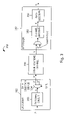
- the system 350 includes an encoder 352 , a decoder 357 and a communication channel 356 .
- the encoder 350 includes an encoding circuit 353 that processes the input data A to produce a codeword X.
- the codeword X includes, for the purposes of error detection and/or correction, some redundancy.
- the codeword X may be transmitted over the communications channel.
- the codeword X can be divided via a data selection device 354 into first and second portions X′, X′′ respectively by some data selection technique.
- One of the codeword portions e.g., the first portion X′, may then be transmitted over the communications channel to a receiver including decoder 357 while the second portion X′′ is punctured.
- portions of the transmitted codeword may be lost or corrupted. From the decoder's perspective, punctured bits may be interpreted as lost.
- soft bits are inserted into the received word to take the place of lost or punctured bits.
- the inserted soft bits indicate erasure of X′′ bits and/or bits lost in transmission.
- the decoder 357 will attempt to reconstruct the full codeword X from the received word Y and any inserted soft bits, and then perform a data decoding operation to produce A from the reconstructed codeword X.
- the decoder 357 includes a channel decoder 358 , e.g., an LDPC decoder, for reconstructing the complete codeword X from the received word Y and any inserted soft bits. In addition it includes a data decoder 359 for removing the redundant information included in the codeword to produce the original input data A from the reconstructed codeword X.
- a channel decoder 358 e.g., an LDPC decoder
- received words generated in conjunction with LDPC coding can be processed by performing LDPC decoding operations thereon, e.g., error correction and detection operations, to generate a reconstructed version of the original codeword.
- the reconstructed codeword can then be subject to data decoding to recover the original data that was coded.
- the data decoding process may be, e.g., simply selecting a specific subset of the bits from the reconstructed codeword.
- LDPC decoding operations generally comprise message passing algorithms.
- message passing algorithms There are many potentially useful message passing algorithms and the use of such algorithms is not limited to LDPC decoding.
- the current invention is directed to methods and apparatus which provide a simple, e.g., low hardware complexity, implementation of an decoder algorithm that gives very good and often near optimal performance in many circumstances.
- the proposed algorithm can be viewed as an approximation of the well-known belief propagation algorithm.
- Belief propagation for (binary) LDPC codes can be expressed as follows. Messages transmitted along the edges of the graph are interpreted as log-likelihoods
- (p 0 ,p 1 ) represents a conditional probability distribution on the associated bit where p x denotes the probability that the bit takes the value x.
- the soft bits provided to the decoder by the receiver are also given in the form of a log-likelihood.
- the received values i.e., the elements of the received word, are log-likelihoods of the associated bits conditioned on the observation of the bits provided by the communication channel.
- a message m represents the log-likelihood m and a received value y represents the log-likelihood y. For punctured bits the log-likelihood received value y is set to 0, indicating
- the outgoing hard decision associated to this output is obtained from the sign of X out .
- FIG. 1 illustrates a bipartite graph representation of an exemplary regular LDPC code of length ten.
- FIG. 2 is a matrix representation of the code graphically illustrated in FIG. 1 .
- FIG. 3 illustrates coding, transmission, and decoding of data.
- FIG. 4 is a bipartite graph representation of an exemplary irregular LDPC code.
- FIG. 5 which comprises the combination of FIGS. 5 a through 5 d, illustrates steps performed as part of an LDPC decoding operation in accordance with the LDPC code illustrated in FIG. 4 .
- FIG. 6 illustrates a serial LDPC decoder including node processors implemented in accordance with the present invention.
- FIG. 7 illustrates an implementation of a variable node processor.
- FIG. 8 illustrates an implementation of a constraint node processor.
- FIGS. 9 and 10 illustrate first and second transform operations, respectively, associated with constraint node processing where ln2 quantization step sizes are used with 5 bit messages.
- FIGS. 11 and 12 illustrate first and second transform operations, respectively, associated with constraint node processing where 1 ⁇ 2 ln2 quantization step sizes are used with 6 bit messages.
- FIG. 13 illustrates the general structure of a node processor, implemented in accordance with the present invention, for use in a message passing decoder.
- FIG. 14 illustrates various messages and values generated during the processing of messages corresponding to nodes of different degrees, in sequence, by the node processor illustrated in FIG. 13 .
- FIG. 15 illustrates and apparatus which can be used for generating quantized log likelihood values from values detected by a receiver.
- the present invention is directed to methods and apparatus for performing decoding operations that are used in conjunction with message passing decoding techniques.
- the techniques of the present invention are particularly well suited for use with LDPC codes.
- log-likelihood values are quantized to integer multiples of 1 ⁇ 2 ln 2.
- Log-likelihood values may be, for example, log likelihood ratios or approximations thereof.
- Log likelihood ratios may be explained as follows. Let x be a bit. Assume that x, possibly together with other bits, are transmitted as a signal and that the receiver observes z as a consequence. The log likelihood ratio for x is defined as
- y log ⁇ p ⁇ ( z
- x 0 ) p ⁇ ( z
- x 1 )
- x 0 ) p ⁇ ( z
- y log ⁇ ⁇ p 0 p 1
- the decoder messages are represented by a finite number of bits.
- a scaling parameter ⁇ In the described exemplary implementations of the invention, messages are integers m and the interpretation of the message is that it represents the log-likelihood m ⁇ .
- our messages are integers which, when scaled by ⁇ in accordance with the invention determine the associated log-likelihoods.
- Incoming messages arrive, e.g., one per clock cycle. It is therefore desirable to have an efficient pipeline structure that can produce one outgoing edge message per clock cycle.
- the present invention also includes a description of a particular structure, a node processor, to implement the above computational rule in this manner.
- the particular implementation provides for an efficient streamlined computation of message passing operations.
- FIG. 4 illustrates an exemplary irregular LDPC code using a bipartite graph 400 .
- the graph includes m check nodes 402 , n variable nodes 406 , and a plurality of edges 404 . Messages between the check nodes and variable nodes are exchanged over the edges 404 .
- Soft input bits y l through y n corresponding to the received word Y, and soft (or hard) outputs x i through x n are indicted by reference numeral 408 .
- the m th check node is identified using reference numeral 402 ′
- the n th variable node is identified using reference numeral 406 ′ while the n th soft input y n and the nth soft output x n are indicated in FIG. 4 using reference numbers 410 , 409 respectively
- Variable nodes 406 process messages from the constraint nodes 402 together with the input soft values from the received word y 1 , . . . , y n to update the value of the output variables x 1 , . . . , x n corresponding to the variable nodes and to generate messages for the constraint nodes.
- One message is generated by a variable node for each edge connected to it. The generated message is transmitted along the edge from the variable node to the constraint node attached to the edge.
- messages from variable nodes to constraint nodes will, from time to time in the present application, be indicated by using the abbreviation V2C while messages from constraint nodes to variable nodes will be indicated by using the abbreviation C2V.
- Each constraint node 402 is responsible for processing the messages received from the variable nodes via the edges.
- the V2C messages received from the variable nodes are processed by the constraint nodes 402 to generate C2V messages which are then transmitted back along the edges attached to each constraint node.
- the variable nodes 406 then process the C2V messages, together with the soft input values, to generate and transmit new V2C messages, and generate soft outputs, x i .
- the sequence of performing processing at the variable nodes 406 comprising: transmitting generated messages to the check nodes 402 , generating at the variable nodes soft outputs x i , and receiving messages from the check nodes, may be performed repeatedly, i.e., iteratively, until the outputs x i from the variable nodes 406 indicate that the codeword has been successfully decoded or some other stopping criterion, e.g., completion of a fixed number of message passing iterations, has been satisfied. It should be appreciated that the sequence of operations described above need not occur strictly in the order described. Node processing may proceed asynchronously and variable and constraint node processing may occur simultaneously. Nevertheless, the logic of the iterative process is as described.
- V2C and C2V may be one or more bits, e.g., K bits each, where K is a positive non-zero integer value.
- the soft outputs x i may be one or more bits. Multiple bit messages and outputs provide the opportunity to relay confidence or reliability information in the message or output.
- the sign of the soft output value may be used to provide the single bit hard output of the decoding process corresponding to a variable node, e.g., the bits of the decoded codeword.
- Output soft values may correspond to decoded soft values or, alternatively, to so-called extrinsic information (excluding the corresponding input information) which may be used in another larger iterative process within which the LDPC decoder is but one module.
- variable and/or constraint node processing may be performed one node at time, e.g., in sequence, until some or all of the variable and constraint node processing has been completed for a particular iteration of the decoding process.
- This allows a single unit of processing hardware to be provided and reused, if desired, to perform the processing associated with each of the variable and/or constraint nodes.
- Another significant feature of LDPC decoding is that the V2C and C2V messages used during a particular processing iteration need not have been generated at the same time, e.g., during the same processing iteration.
- FIG. 5 a illustrates the initial step in an LDPC decoding process.
- the variable node V n 506 ′ is supplied with the soft input, e.g., the received values (1 or more bits representing a log-likelihood) y n from a received word to be processed.
- the C2V messages at the start of a decoding operation and the soft output X n 509 are initially set to zero.
- the variable node V n 506 ′ Based on the received inputs, e.g., the zero value C2V messages and input y n , the variable node V n 506 ′ generates one V2C message for each check node to which it is connected. Typically, in the initial step, each of these messages will be equal to y n .
- V2C messages are shown being transmitted along each of the edges connected to variable node V n 506 ′.
- updated V2C messages are transmitted to each of the check nodes 502 coupled to variable node V n 506 ′ including check node C m 502 ′.
- variable node processing results in the updating of the soft output X n 509 ′ corresponding to the variable node doing the processing.
- the soft output X n is shown being updated in FIG. 5 c. While shown as different steps, the soft output may be output at the same time the V2C messages are output.
- the soft outputs may be used to determine when a codeword has been recovered from the received word, i.e., when the parity constraints have been satisfied by the output values. This indicates successful decoding (although the codeword found may be incorrect, i.e., not the one that was transmitted) thereby allowing the iterative decoding process to be halted in a timely fashion, e.g., before some fixed maximum allowed number of message passing iterations is completed.
- Check node processing can be performed once a check node, e.g., check node C m 502 ′, receives V2C messages along the edges to which it is connected.
- the received V2C messages are processed in the check node to generate updated C2V messages, one for each edge connected to the particular check node.
- the C2V message transmitted back to a variable node along an edge will depend on the value of each of the V2C messages received on the other edges connected to the check node but (usually and preferably) not upon the V2C message received from the particular variable node to which the C2V message is being transmitted.
- C2V messages are used to transmit information generated from messages received from variable nodes other than the node to which the message is being transmitted.
- FIG. 5 d illustrates the passage of updated C2V messages to variable nodes including node 506 ′.
- constraint node C m 502 ′ is shown outputting two updated C2V messages with the updated C m 2V n message being supplied to variable node V n 506 ′.
- V n 506 ′ also receives additional updated C2V n message(s) from another constraint node(s) to which it is connected.
- variable node processing can be repeated to generate updated V2C messages and soft outputs. Then the updating of C2V messages can be further repeated and so on until the decoder stopping criterion is satisfied.
- FIGS. 5 a - 5 d will be repeated after the first iteration, using updated message values as opposed to initial values, until the decoding process is stopped.
- the present invention concerns the form of messages passed, the computation performed thereon, and hardware structures that perform these computations.
- an LDPC decoder implementation This implementation is for illustrative purposes. Efficient implementation architectures are discussed in U.S. patent application Ser. No. 09/975,333 filed Oct. 10, 2001 titled: “Methods and Apparatus for Decoding LDPC codes” which is hereby expressly incorporated by reference.
- message passing decoding input values y are in the form of log-likelihood values which are quantized to be integer multiples of 1 ⁇ 2 ln 2.
- the generation of quantized log-likelihood values may involve processing received values to generate therefrom log-likelihood values, e.g., ratios, or approximations thereof.
- the log-likelihood values are then quantized using step sizes which are integer ratios of 1 ⁇ 2 ln 2 to produce the quantized log-likelihood values.
- the log-likelihood values are, in various embodiments, log-likelihood ratios or approximations thereof. The use of such quantized log-likelihood ratios facilitates decoder implementation.
- Circuitry for generating quantized log-likelihood values, e.g., ratios, from received values may be incorporated directly into a receiver which forms part of the communications channel 356 that precedes the message passing decoder of the present invention, e.g., decoder 600 shown in FIG. 6 .
- FIG. 15 an exemplary circuit 1500 for generating a quantized log-likelihood ratio y o , from a received value y in , is shown.
- the FIG. 15 circuit is suitable in cases of BPSK (+1, ⁇ 1) signaling with additive Gaussian noise, where it may be assumed that each received value is proportional to the log-likelihood ratio for the associated bit. In such a case, the received value may be converted to a log-likelihood ratio by simply multiplying by a constant.
- the value y in may be a value received by a receiver circuit which is processed to produce the log-likelihood ratio y 0 supplied by a message passing decoder of the present invention.
- the circuit 1500 includes a multiplier 1502 for generating log-likelihood ratios by multiplying the input value Y in by (2/s 2 ) where s 2 is a constant corresponding to the additive Gaussian noise introduced by the communications channel into the received signal.
- the resulting log-likelihood ratio is then quantized by quantizer 1504 to be an integer multiple of 1 ⁇ 2 ln 2.
- Quantizer 1504 may be implemented by dividing the log-likelihood ratio generated by multiplier 1502 by 1 ⁇ 2 ln 2 and then saturating the result to +15 or ⁇ 15 when the magnitude exceeds 15 and otherwise taking the 5 lsbs (least significant bits) of the resulting value as the quantized log-likelihood ratio Y o which may then be supplied as an input to decoder circuit 600 .
- FIG. 6 depicts a simple serial decoder 600 which performs message processing operations sequentially, one edge at a time.
- the LDPC decoder 600 comprises a decoder control module 610 , a V2C edge memory 630 , a C2V edge memory 650 , a variable node processor 620 , a constraint node processor 640 , and output buffer 660 .
- the decoder runs for a fixed number of iterations, i.e., no convergence detection is performed.
- V2C and C2V edge memories 630 , 650 each include L K bit memory locations with each K bit location corresponding to one edge and where L is the total number of edges in the LDPC graph being used and K is the number of bits per message exchanged along an edge.
- the output buffer 660 includes memory for storing variable node output values x, which may be either hard (1 bit) or soft (more than 1 bit) values.
- the decoder control module 610 includes information describing the graph in stored form. It uses this information to control the message passing as described below. Each received value and message is assumed to be comprised of K bits.
- the decoder operates serially. It first performs variable node update operations and then constraint node update operations. It repeats this cycle some fixed number of times concluding after a final variable node update. Initially the C2V message memory is populated with zeroes. (Note that variable node processing and constraint node processing may be physically concurrent in time. The ordering described above indicates the flow of information during the processing.)
- the decoder control module 610 causes the C2V messages to be read out of the C2V message memory in variable node socket order and to be delivered to the variable node processor 620 .
- the decoder control module 610 signals to the C2V edge message memory 650 a message identifier (e.g., memory location or pointer) indicating which message is to be read out at that point in time.
- a message identifier e.g., memory location or pointer
- variable node processor 620 receives from the decoder control module 610 a signal, the node clock signal, that indicates node boundaries. This signal informs the variable node processor, in effect, about the degree of the node currently being processed.
- the signal can, and in various embodiments is, sent, e.g., at the point in time coincident with the arrival of the last incoming messages corresponding to a particular node.
- Node update computations are performed in the variable node processor 620 .
- Outgoing V2C messages are emitted in variable socket order, i.e., corresponding to the edge order of the incoming messages, and these messages are stored in V2C edge message memory 630 .
- Soft or hard output values are stored in the output buffer 660 .
- the decoder control module 610 causes the V2C messages to be read out of the V2C message memory 630 in constraint socket order and to be delivered to the constraint node processor 640 .
- the decoder control module 610 signals to the V2C edge message memory 630 a message identifier (e.g., memory location) indicating which message is to be read out.
- Messages for a given constraint node are processed by the constraint node processor 640 .
- the constraint node processor 640 receives a signal, the node clock signal, from the decoder control module 610 that indicates node boundaries.
- Outgoing C2V messages are emitted in constraint socket order, i.e., corresponding to the edge order of the incoming messages, and these messages are stored in C2V edge message memory 650 .
- variable node update and the constraint node update comprise a complete iteration. (As remarked above, the variable and constraint node processing may occur concurrently.)
- node processor features of the present invention will now be described in the context of the exemplary LDPC decoder system 600 shown in FIG. 6 .
- the node processor may be replicated to provide parallel processing of several nodes at once.
- the five bits of a message represent possible integer values ⁇ 15, ⁇ 14, . . . , ⁇ 1, 0, 1, . . . , 15 ⁇ .
- a sign takes the value 0 or 1 indicating the preferred value, e.g., the associated hard decision, for the associated bit.
- the magnitude indicates the reliability of the sign: Larger magnitudes indicate higher reliability.
- the sign may be chosen arbitrarily.
- the outgoing message magnitude exceeds 15 it is saturated, e.g., set to 15.
- FIGS. 7 and 8 illustrate an exemplary implementation of this rule for the serial decoder described above.
- FIG. 7 illustrates an implementation of a variable node processor 700 suitable for the decoder depicted in FIG. 6 .
- Messages (m) for a particular variable node arrive in sequence.
- Each message, m includes K bits.
- Each received message is summed by the summer 710 with a previous sum, i.e., an accumulated message sum, output by unit delay element 712 .
- the accumulated message sum supplied to summer 710 is reset to “0” with the receipt of a message corresponding to a new node.
- the received soft input value y is added in adder 720 to the accumulated message sum output by delay 712 , to form a new accumulated sum SUM.
- the value SUM is latched and stored in latch 730 .
- This latching occurs as the result of an external node clock signal whose timing is controlled to guarantee that the complete sum is latched.
- the node clock signal is determined as a function of the node degree.
- Each received message is also passed through a delay line including variable delay element 760 whose duration corresponds to the degree of the node being implemented.
- the first message associated to the particular variable node being processed emerges from the delay line and the message's value is subtracted from the latched total sum stored in latch 730 by adder 740 .
- the outgoing result is subsequently passed through a saturation operator 770 to ensure that the outgoing message value is in the desired range, e.g., limited to K-bits.
- Unit delay elements 742 and 772 positioned before and after saturation operator 770 are used to synchronize variable node processing operations with constraint node processing operations.
- FIG. 8 illustrates an implementation of a constraint node processor 800 suitable for use in the decoder depicted in FIG. 6 .
- the check node processor 800 includes a splitter circuit 801 , a sign processing circuit 802 , a magnitude processing circuit 804 and a combining circuit 899 .
- messages m for a particular check node arrive in sequence.
- the constraint node update is separated into sign and magnitude update processing with divider 801 being used to separate the sign bit from the magnitude information in the message.
- the single sign bit of the received message is split off by separating circuit 801 and supplied to a sign bit processing circuit 802 for processing.
- the remaining K-1 bits of the K-bit message, m are supplied to a message processing circuit 804 .
- node clock and node degree signals are supplied to corresponding inputs of both the sign and magnitude processing circuits 802 , 804 .
- Incoming sign bits are delayed one clock cycle by unit delay element 803 prior to being supplied to an input of exclusive OR (XOR) logic circuit 810 .
- XOR circuit 810 performs an exclusive-or or modulo 2 sum of the incoming sign bit and a previous XOR result which is delayed by a second unit delay element 815 prior to being supplied to a second input of the XOR circuit 810 . In this manner, XORing of all the sign bits corresponding to the node being processed produces a total XOR result or product, SUM sign , through iterative processing.
- the value SUM sign is stored in latch 830 under control of the node clock signal 830 for subsequent XORing with delayed sign bits corresponding to the node.
- MUX 813 is used to output the value 0 to be XORed with the sign bit of the first message corresponding to a node. At other times it outputs the delayed XOR result.
- each sign bit is also passed through a delay line which includes variable delay element 820 .
- the delay of element 820 is controlled by the node degree signal so that the duration of the delay imposed on the sign bit will correspond to the degree of the node.
- SUM sign the total sum (exclusive-or), which we denote as SUM sign .
- variable node update the sign bits emerge from the delay line in sequence.
- the value of the delayed sign bit is subtracted (exclusive-or operation) from SUM sign in an adder 840 .
- the result constitutes the sign of the outgoing message. Note that some additional delay elements 841 , 843 have been inserted into the processor 802 , to keep the sign update synchronized with magnitude update performed by circuit 804 .
- the goal of this transform process is to represent the message values in a form in which constraint processing can be implemented through the use of simple sums and subtractions.
- this transform can be implemented as a shift operation: the value C is stored in binary form and it is shifted to the right by m r V2C (i) to obtain the transformed message. For the 5 bit decoder example the value C found to be effective is given by 6000 in hexadecimal notation.
- step 906 a constant C, used to convert between the variable node and constraint node domains, is shifted to the right by the decimal value (number) of places indicated by the magnitude portion of the received message.
- zeros are inserted in the left bit positions (high order bits) vacated as a result of the shift operation.
- step 908 the magnitude portion 910 (e.g., 15 bits) of the message now in constraint node form is output for further processing.
- the output value represents a transformed magnitude value suitable for constraint node processing through addition operations.
- the transformed magnitudes are passed through unit delay element 851 prior to being supplied to summer 860 and variable delay element 880 .
- a sum of transformed edge message magnitudes is created by using summer 860 to add the edge message output by delay element 851 to the delayed output of the summer 860 thereby creating an accumulated sum, SUM mag .
- the accumulated sum, SUM mag is stored in latch 870 upon receipt of the node clock signal indicating that all the edge messages corresponding to the node have been summed together.
- the node clock signal is also used to control mux 863 to output a “0” when the first message corresponding to a node is supplied to summer 860 .
- mux 860 allows for the resetting of the accumulated sum at the start of processing of messages corresponding to each of a plurality of nodes.
- the delayed transformed edge message magnitudes subsequently emerge from the delay line 880 and their values are subtracted from the stored sum SUM mag in an adder 890 prior to being supplied to unit delay element 891 . Then, an inverse transform is performed on the delayed outgoing magnitude obtained from delay element 891 by transform circuit 895 .
- This second transform circuit which performs a transform from the constraint node to the variable node message representation, in one exemplary embodiment, operates as follows.
- FIG. 10 is a flow chart illustrating the transform process 1000 performed in step 895 which involves the conversion of the message magnitude value from the constraint node domain back into the variable node domain representation.
- the message magnitude may include more bits (e.g., the message be 20 bits long) than at the output of step 850 (e.g., where the message was 15 bits long), due to the message summing and subtraction operations performed in steps 860 and 891 .
- step 1004 the magnitude portion 1002 of a message in constraint node domain form is received and the position of the first “1” from the left is determined by counting bit positions from the right. For example, if the magnitude portion 1002 was (00000010000000000100) a priority encoder could be used to determine that the first 1 bit from the left occurs in bit position 14 as measured from the right.
- step 1006 the determined bit position is compared to the maximum value which can be represented by the number of bits used to represent the message magnitudes in the variable node domain form. For example, if 4 bits were used for message magnitudes in the variable node domain the maximum value would be 15. In such a case, if the determined bit position was greater than 15 operation would proceed to step 1008 . Otherwise operation proceeds from step 1006 to step 1010 .
- step 1008 all the bits in the variable node domain message magnitude representation, e.g., 4 bits, are set to zero thereby generating the variable node domain form of the received constraint node message magnitude 1002 .
- step 1012 the message magnitude 1014 now in variable node domain magnitude form is output, e.g., to delay element 897 .
- the constraint node processor it will be more convenient to store reliabilities in the delay line 880 in the variable domain form rather than the constraint domain form. This can reduce complexity since the variable domain form requires significantly fewer bits than the constraint domain form.
- the functional block 850 would be replicated at the output of the delay line 880 and the input to the delay line would be taken before the functional block 880 rather than after.
- a spacing of 2ln2 for the log-likelihood ratios may be more desirable than the discussed exemplary ln2 spacing.
- This case will typically be used in conjunction with messages comprised of fewer bits.
- the change from ln2 to 2ln2 will change the update rules discussed above at the constraint nodes but not the variable nodes.
- the modification at the constraint nodes amounts to noticing that all messages are as in the case for ln2 spacing but only even valued magnitudes are allowed and, in this case, the last bit of the magnitude will always be 0 and need not, and in various embodiments will not, be passed as part of the message.
- FIGS. 11 and 12 depict the forward and reverse transformation processes 1100 , 1200 for 1 ⁇ 2 ln2 spacing embodiments, which correspond to the transforms shown in FIGS. 9 and 10 , respectively, for the ln2 spacing embodiment.
- the update rules e.g., transform operations 850 and 895 , change at the constraint nodes but not the variable nodes.
- the transformation to the constraint node domain proceeds as in the ln2 spacing case except that the least significant bit, e.g., the fifth bit in a 5 bit magnitude representation, of the incoming magnitude is dropped, i.e., the message magnitude value is shifted to the right by one, or, equivalently, divided by 2.
- the least significant bit is a 1 the same operation is performed but the constant C used in the transformation will be different. In such a case the constant C will be replaced by a slightly smaller value falling in between C and C/2.
- Constraint node processing proceeds as before up to the point of the inverse transformation using the remaining bits of the magnitude portion of the message being processed.
- FIG. 11 illustrates the process 1100 of transforming a magnitude message portion 1102 in the variable node domain form to the constraint node domain form in the case where 1 ⁇ 2 ln2 spacing is used.
- the LSB e.g., bit 5 is split from the magnitude portion of the message and supplied to step 1100 while the remaining bits, e.g., the 4 higher order bits are supplied to step 1106 .
- the value C is supplied from step 1113 or 1114 to step 1106 which also receives the remaining higher order bits, e.g., 4 bits, of the message magnitude portion 1102 .
- step 1106 the constant C is shifted to the right by the number of places specified by the decimal value of the remaining bits (e.g., 4 bits) of the message magnitude and zeros are inserted into the left bit positions vacated as a result of the shift operation.
- step 1108 the message magnitude 1110 (15 bits), now in constraint node domain magnitude form, are output to e.g., delay element 851 .
- the inverse transformation e.g., constraint node domain representation to variable node domain representation
- the inverse transformation involves an additional step beyond that present in the ln2 spacing case which is used to determine the least significant bit of the outgoing message.
- the value obtained using the ln2 spacing rule provides the other, higher order, bits in the message.
- the constraint node domain value v is compared with the threshold value t 2 1(v) where t is some appropriate predetermined constant. If v is larger than t 2 1(v) than the LSB is set to 0 otherwise it will be set to 1. It will be appreciated that there are many alternative implementations using the same threshold rule.
- FIG. 12 illustrates the process 1200 of converting a magnitude portion 1202 of a message in constraint node domain form to variable node domain form.
- the processes begins in step 1204 wherein the location of the first “1” from the left as measured from the right is determined. A priority encoder may be used to perform this operation.
- step 1208 Processing proceeds to step 1208 , as a result of a determination that the message magnitude should be set to zero.
- step 1208 all bits in the variable node domain message magnitude representation are set to zero to generate the message magnitude (e.g., 00000) in the variable node domain form. With the transform complete, operation proceeds from step 1208 to step 1214 .
- step 1210 which represents an alternative processing path to step 1208 , the identified number, i.e., number of the bit position, is subtracted from the largest value that can be represented by the number of non-LSB bits of a message magnitude in the variable node domain form. For example, assuming a 5 bit magnitude representation in the variable node domain form, there are 4 bits in addition to the LSB. The largest number that can be represented by 4 bits is 15. Accordingly, in such an embodiment in step 1210 , the number of the identified bit position would be subtracted from 15 to produce the 4 high order bits of the magnitude value in the variable node domain.
- the LSB e.g., the fifth bit of the 5 bit exemplary magnitude value, is determined from the value of one or more bits to the right of the leftmost “1” present in the magnitude value in the constraint node domain representation 1202 of the message magnitude.
- step 1214 the generated message magnitude 1216 , e.g., 5 bits, now in variable node form is output, e.g., to unit delay element 897 .
- FIGS. 7 and 8 include one and two instances, respectively, of a basic structure which we further describe in reference to FIG. 13 . Recall that the dominant computation for message updates has the simplified form:
- the hardware design of the present invention gives due consideration to the following observations and supports the listed features:
- a message processing system 1300 representing a generalized proposed pipeline structure, is illustrated in FIG. 13 .
- the processing system 1300 sequentially receives input messages “A”, one per clock cycle as determined by an edge clock signal used to drive the various system components. It also receives a node clock signal and a node degree signal.
- the node clock signal serves as a node framing signal and is asserted when a message corresponding to a new node is supplied to the message input of accumulator module 1302 .
- the node clock signal is used to control various operations, including the initialization of a running message sum and the latching of a total sum, generated for each node.
- the node clock signal is generated as a function of the degree, e.g., number of messages, corresponding to the node for which processing is being implemented.
- the node degree signal indicates the degree of the node for which processing is being performed and thus the number of messages that correspond to the node.
- the node degree signal is used to control a variable delay element 1306 used to delay the received messages. Operation of the system 1300 will be discussed further below with reference to the corresponding data flow shown in FIG. 14 . For simplicity any pre- and post-processing stages are skipped and simple addition and subtraction operations assumed.
- the processing system 1300 comprises two computational stages, sometimes referred to as modules, i.e., an accumulation module “A” 1302 and a subtraction module “S” 1304 . Since the subtraction module generates output messages it is sometimes also called a message generation module.
- the system 1300 also comprises a variable message delay path which includes a variable delay element 1306 which outputs delayed messages “D”.
- the accumulation module “A” 1302 receives input messages in sequence and generates, for each set of messages corresponding to a node, a total sum.
- Accumulation module 1302 comprises a summer 1310 , unit delay element 1312 , a mux 1314 and a node sum latch 1316 .
- the unit delay element 1312 is used to store a running sum generated by summer 1310 .
- MUX 1314 supplies either a zero or the running sum output by delay element 1312 , to one of the inputs of summer 1310 .
- the MUX is controlled by the node clock signal to output the zero when the first message corresponding to a node is supplied to the other input of the summer 1310 and the running sum B at all other times. In this manner, summer will add received messages corresponding to a node to generate a total sum for the node.
- the node clock signal is also used to strobe the running sum into the node sum latch 1316 .
- the running sum represents a total sum for the node.
- the subtraction or message generation module “S” 1304 receives as its input the total sum generated by the accumulation module 1302 and the input messages delayed by variable delay element 1306 . Stage “S” 1304 sequentially subtracts delayed input messages from the total sum “C” stored in node sum latch 1316 producing output messages for a node, e.g., node N, one message per clock cycle.
- the results of the subtraction operation, an output message “E” is stored in an output register 1321 prior to being output by Operation of stages “A” 1302 and “S” 1304 can be fully overlapped or folded. For example, while stage “A” 1302 is performing processing for node N+1, stage “S” can perform processing for node N.
- variable delay line which includes delay element 1306 is to supply delayed original input messages, represented as “D”, for node N to subtraction stage “S” while storing input messages for node N+1.
- variable delay element 1306 is implemented with at least enough storage space to store as many messages as the highest node degree to be supported.
- variable delay element 1306 and delayed message D saves message memory bandwidth by removing duplicated reads required for folded pipeline operation.
- the delay line, including delay element 1306 can be practically implemented either with external delay value control (e.g. shift register with variable output tap) or with internal delay value control (e.g. self-contained FIFO).
- the first method may be preferable for vector decoders as the delay control logic can be shared across multiple processing nodes.
- the pipeline structure described above allows the node degree to be changed on the fly by altering both the frequency of the node clock signal used for node framing signal and changing the degree signal used to control the message delay imposed by delay element 1306 .
- pipeline depth can easily be changed.
- the pipeline depth may be interpreted as the delay from the time the first incoming message (for node N) is fed into the system 1300 for processing to the time the first outgoing message E (for node N) appears at the pipeline output.
- Variable depth pipeline can offer significant performance advantage where irregular LDPC codes are to be supported since the total number of cycles required per iteration is equal to the number of edge edges in the graph plus the degree spread (the difference between the maximum and minimum degrees).
- FIG. 14 illustrates a chart 1400 which includes an example of the various values, A through D, present in the system 1300 at a point in time where a switch from node degree 3 to node degree 4 occurs. Note that there are no pipeline stalls, e.g., delays with respect to input data arrival, due to the switch in node degree.
- FIG. 14 illustrates the processing associated with messages corresponding to four nodes, node 1 (n 1 ), node 2 (n 2 ), node 3 (n 3 ) and node 4 (n 4 ).
- Cells in the FIG. 14 chart including a single line correspond to n 1 .
- Cells which include two lines correspond to n 2 .
- Cells which include three lines correspond to n 3 .
- cells which include four lines correspond to n 4 .
- nodes n 1 and n 2 are of degree 3 while nodes n 3 and n 4 are of degree 4 .
- Each row in chart 1400 corresponds to a different clock cycle while columns correspond to different values as indicated.
- the second column 1402 lists the received messages A, in the order they are received, one per clock cycle.
- the third column 1404 lists the running sum B, during each processing clock cycle. Note that in column 1404 , the node indicator, e.g., n 1 from the message n 1 _e 0 , is omitted in column 1404 for the purposes of brevity.
- the fourth column 1406 lists the latched total sum C generated for each node as part of the message processing.
- the fifth column 1408 lists the delayed value D output by the delay element 1306 which is subtracted from a sum in column C to produce the output message E.
- the generated output messages are listed in the sixth column 1410 .
- LDPC decoding methods and node processor implementations allow for LDPC decoding to be performed on various hardware platforms such as Field Programmable Gate Arrays or in an Application Specific Integrated Circuit.
- the present invention is especially useful in these settings where the simple parallelism and easy to implement nodes can be explicitly exploited.
Abstract
Description
for the bit associated to the variable node. Here, (p0,p1) represents a conditional probability distribution on the associated bit where px denotes the probability that the bit takes the value x. The soft bits provided to the decoder by the receiver are also given in the form of a log-likelihood. Thus, the received values, i.e., the elements of the received word, are log-likelihoods of the associated bits conditioned on the observation of the bits provided by the communication channel. In general, a message m represents the log-likelihood m and a received value y represents the log-likelihood y. For punctured bits the log-likelihood received value y is set to 0, indicating
The outgoing decoded soft value from a node (not an edge message) corresponding to this operation is given by
The outgoing hard decision associated to this output is obtained from the sign of Xout.
where we define F(x):=ln coth (x/2). In both of the above equations the superscript V2C denotes the incoming messages at the constraint node. We note that F is its own inverse, i.e., F−1(x)=F(x).
where p(z|x=i) denotes the conditional probability of observing z given the condition x=i. There are many possible methods and forms for computing y depending on the signaling scheme, the channel model, etc. Assuming that the two possibilities for x are a priori equally likely, the likelihood ratio
is equal to the ratio of the posterior probabilities of x given z, i.e.,
Thus, we often denote the log likelihood ratio as simply
where pi denotes a conditional probability that x=i. During various LDPC decoding embodiments of the invention we compute, at least approximately, such log likelihood ratios (e.g. the messages) where the conditioning information is increasing with each iteration.
where [x] denotes the integer part of x.
Since it is the integer part of the log2 function that we use, the function can be implemented as a priority encoder, that is, one can implement the function by simply determining the location of the first 1 exemplary bipartitein the binary representation of the argument.
at the variable nodes, and take the form
at the check nodes, where C1 and C2 are constants and “Priority” refers to the operation of finding the first ‘1’ in a suitable binary representation of the argument. We will elaborate more on the meaning and exemplary implementations of the priority encoder in the detailed description which follows.
We propose to perform the message passing operations serially in time. Incoming messages arrive, e.g., one per clock cycle. It is therefore desirable to have an efficient pipeline structure that can produce one outgoing edge message per clock cycle. The present invention also includes a description of a particular structure, a node processor, to implement the above computational rule in this manner. The particular implementation provides for an efficient streamlined computation of message passing operations.
When the outgoing message mV2C(j) has the
and that it is desirable to have an efficient pipeline structure that can produce one outgoing edge message per clock cycle. The hardware design of the present invention gives due consideration to the following observations and supports the listed features:
-
- there is no explicit dependency between input and output data, allowing the pipeline to be sufficiently deep to allow very high clock rate;
- the pipeline is able to maintain it's efficiency while processing nodes of variable degree;
- addition and subtraction in the formula above can be generalized to any operation that has an inverse and follows associative law (modulo addition/subtraction, multiplication/division etc);
- the pipeline may include additional pre- and post-processing stages such as function transform, saturation, delay elements, etc.
Claims (11)
Priority Applications (1)
| Application Number | Priority Date | Filing Date | Title |
|---|---|---|---|
| US11/178,951 US7673223B2 (en) | 2001-06-15 | 2005-07-11 | Node processors for use in parity check decoders |
Applications Claiming Priority (5)
| Application Number | Priority Date | Filing Date | Title |
|---|---|---|---|
| US29848001P | 2001-06-15 | 2001-06-15 | |
| US32846901P | 2001-10-10 | 2001-10-10 | |
| US09/975,331 US6633856B2 (en) | 2001-06-15 | 2001-10-10 | Methods and apparatus for decoding LDPC codes |
| US10/117,264 US6938196B2 (en) | 2001-06-15 | 2002-04-04 | Node processors for use in parity check decoders |
| US11/178,951 US7673223B2 (en) | 2001-06-15 | 2005-07-11 | Node processors for use in parity check decoders |
Related Parent Applications (3)
| Application Number | Title | Priority Date | Filing Date |
|---|---|---|---|
| US09/975,331 Continuation-In-Part US6633856B2 (en) | 2001-06-15 | 2001-10-10 | Methods and apparatus for decoding LDPC codes |
| US10/117,264 Continuation US6938196B2 (en) | 2001-06-15 | 2002-04-04 | Node processors for use in parity check decoders |
| US10/117,264 Continuation-In-Part US6938196B2 (en) | 2001-06-15 | 2002-04-04 | Node processors for use in parity check decoders |
Publications (2)
| Publication Number | Publication Date |
|---|---|
| US20050257124A1 US20050257124A1 (en) | 2005-11-17 |
| US7673223B2 true US7673223B2 (en) | 2010-03-02 |
Family
ID=35310755
Family Applications (1)
| Application Number | Title | Priority Date | Filing Date |
|---|---|---|---|
| US11/178,951 Expired - Fee Related US7673223B2 (en) | 2001-06-15 | 2005-07-11 | Node processors for use in parity check decoders |
Country Status (1)
| Country | Link |
|---|---|
| US (1) | US7673223B2 (en) |
Cited By (13)
| Publication number | Priority date | Publication date | Assignee | Title |
|---|---|---|---|---|
| US20090319861A1 (en) * | 2008-06-23 | 2009-12-24 | Ramot At Tel Aviv University Ltd. | Using damping factors to overcome ldpc trapping sets |
| US20100031115A1 (en) * | 2008-08-04 | 2010-02-04 | Ara Patapoutian | Low density parity check decoder using multiple variable node degree distribution codes |
| US20100070818A1 (en) * | 2008-09-17 | 2010-03-18 | Ulriksson Bengt A | Node processor for use with low density parity check decoder using multiple variable node degree distribution codes |
| US8266493B1 (en) * | 2008-01-09 | 2012-09-11 | L-3 Communications, Corp. | Low-density parity check decoding using combined check node and variable node |
| US8527849B2 (en) * | 2011-08-19 | 2013-09-03 | Stec, Inc. | High speed hard LDPC decoder |
| US8862959B1 (en) * | 2013-01-23 | 2014-10-14 | Apple Inc. | Sign equalization in iterative decoding of sparse graph codes |
| US8971213B1 (en) * | 2011-10-20 | 2015-03-03 | Cisco Technology, Inc. | Partial association identifier computation in wireless networks |
| US9276610B2 (en) * | 2014-01-27 | 2016-03-01 | Tensorcom, Inc. | Method and apparatus of a fully-pipelined layered LDPC decoder |
| US9391817B2 (en) | 2014-03-24 | 2016-07-12 | Tensorcom, Inc. | Method and apparatus of an architecture to switch equalization based on signal delay spread |
| US10374630B2 (en) | 2016-07-19 | 2019-08-06 | Samsung Electronics Co., Ltd. | Low-density parity check decoder, a storage device including the same, and a method |
| CN110289863A (en) * | 2015-10-13 | 2019-09-27 | 华为技术有限公司 | Decoding equipment, method and signal transmission system |
| US10778371B2 (en) * | 2016-11-02 | 2020-09-15 | Qualcomm Incorporated | Deeply-pipelined high-throughput LDPC decoder architecture |
| US11231993B2 (en) | 2018-11-29 | 2022-01-25 | Western Digital Technologies, Inc. | Symbol-based variable node updates for binary LDPC codes |
Families Citing this family (23)
| Publication number | Priority date | Publication date | Assignee | Title |
|---|---|---|---|---|
| KR100602027B1 (en) * | 2002-07-03 | 2006-07-19 | 휴우즈 일렉트로닉스 코오포레이션 | Bit-interleaved coded modulation using low density parity check ldpc codes |
| US7020829B2 (en) * | 2002-07-03 | 2006-03-28 | Hughes Electronics Corporation | Method and system for decoding low density parity check (LDPC) codes |
| US7577207B2 (en) * | 2002-07-03 | 2009-08-18 | Dtvg Licensing, Inc. | Bit labeling for amplitude phase shift constellation used with low density parity check (LDPC) codes |
| US20040019845A1 (en) * | 2002-07-26 | 2004-01-29 | Hughes Electronics | Method and system for generating low density parity check codes |
| US7864869B2 (en) * | 2002-07-26 | 2011-01-04 | Dtvg Licensing, Inc. | Satellite communication system utilizing low density parity check codes |
| JP4062435B2 (en) * | 2002-12-03 | 2008-03-19 | 日本電気株式会社 | Error correction code decoding apparatus |
| CN101341659B (en) * | 2004-08-13 | 2012-12-12 | Dtvg许可公司 | Code design and implementation improvements for low density parity check codes for multiple-input multiple-output channels |
| US8675176B2 (en) * | 2005-02-25 | 2014-03-18 | Asml Netherlands B.V. | Parameter control in a lithographic apparatus using polarization |
| KR101157246B1 (en) * | 2005-05-16 | 2012-06-15 | 삼성전자주식회사 | Padding and puncturing method for ldpc channel code |
| US20070089016A1 (en) * | 2005-10-18 | 2007-04-19 | Nokia Corporation | Block serial pipelined layered decoding architecture for structured low-density parity-check (LDPC) codes |
| US20070089019A1 (en) * | 2005-10-18 | 2007-04-19 | Nokia Corporation | Error correction decoder, method and computer program product for block serial pipelined layered decoding of structured low-density parity-check (LDPC) codes, including calculating check-to-variable messages |
| JP4807063B2 (en) * | 2005-12-20 | 2011-11-02 | ソニー株式会社 | Decoding device, control method, and program |
| GB2434946B (en) * | 2006-02-01 | 2008-07-23 | Toshiba Res Europ Ltd | Wireless communications apparatus |
| US8418023B2 (en) | 2007-05-01 | 2013-04-09 | The Texas A&M University System | Low density parity check decoder for irregular LDPC codes |
| WO2009046534A1 (en) * | 2007-10-11 | 2009-04-16 | The Royal Institution For The Advancement Of Learning/Mcgill University | Methods and apparatuses of mathematical processing |
| US8327215B2 (en) * | 2007-12-13 | 2012-12-04 | Electronics And Telecommunications Research Institute | Apparatus and method for encoding LDPC code using message passing algorithm |
| US8301979B2 (en) * | 2008-10-07 | 2012-10-30 | Sandisk Il Ltd. | Low density parity code (LDPC) decoding for memory with multiple log likelihood ratio (LLR) decoders |
| US9047153B2 (en) * | 2010-02-22 | 2015-06-02 | Analog Devices, Inc. | Selective delay of data receipt in stochastic computation |
| CN107124186B (en) * | 2017-03-17 | 2020-06-19 | 上海交通大学 | Two-stage decoding method of LDPC code based on grid complexity |
| CN109995380B (en) * | 2018-01-02 | 2021-08-13 | 华为技术有限公司 | Decoding method and apparatus |
| US11088707B2 (en) | 2019-06-29 | 2021-08-10 | Intel Corporation | Low density parity check (LDPC) decoder architecture with check node storage (CNS) or bounded circulant |
| US11515891B2 (en) | 2020-12-22 | 2022-11-29 | Intel Corporation | Application of low-density parity-check codes with codeword segmentation |
| US20240022262A1 (en) * | 2022-07-13 | 2024-01-18 | Apple Inc. | Scheduling of iterative decoding depending on soft inputs |
Citations (56)
| Publication number | Priority date | Publication date | Assignee | Title |
|---|---|---|---|---|
| US3542756A (en) | 1968-02-07 | 1970-11-24 | Codex Corp | Error correcting |
| US3665396A (en) | 1968-10-11 | 1972-05-23 | Codex Corp | Sequential decoding |
| US4295218A (en) | 1979-06-25 | 1981-10-13 | Regents Of The University Of California | Error-correcting coding system |
| US4449190A (en) * | 1982-01-27 | 1984-05-15 | Bell Telephone Laboratories, Incorporated | Silence editing speech processor |
| US4561092A (en) | 1983-05-13 | 1985-12-24 | The Bdm Corporation | Method and apparatus for data communications over local area and small area networks |
| US4726037A (en) * | 1986-03-26 | 1988-02-16 | American Telephone And Telegraph Company, At&T Bell Laboratories | Predictive communication system filtering arrangement |
| US4914657A (en) | 1987-04-15 | 1990-04-03 | Allied-Signal Inc. | Operations controller for a fault tolerant multiple node processing system |
| US5146324A (en) * | 1990-07-31 | 1992-09-08 | Ampex Corporation | Data compression using a feedforward quantization estimator |
| US5157671A (en) | 1990-05-29 | 1992-10-20 | Space Systems/Loral, Inc. | Semi-systolic architecture for decoding error-correcting codes |
| US5271042A (en) | 1989-10-13 | 1993-12-14 | Motorola, Inc. | Soft decision decoding with channel equalization |
| US5293489A (en) | 1985-01-24 | 1994-03-08 | Nec Corporation | Circuit arrangement capable of centralizing control of a switching network |
| US5313609A (en) | 1991-05-23 | 1994-05-17 | International Business Machines Corporation | Optimum write-back strategy for directory-based cache coherence protocols |
| US5317672A (en) * | 1991-03-05 | 1994-05-31 | Picturetel Corporation | Variable bit rate speech encoder |
| US5396518A (en) | 1993-05-05 | 1995-03-07 | Gi Corporation | Apparatus and method for communicating digital data using trellis coding with punctured convolutional codes |
| US5457704A (en) | 1993-05-21 | 1995-10-10 | At&T Ipm Corp. | Post processing method and apparatus for symbol reliability generation |
| US5526501A (en) | 1993-08-12 | 1996-06-11 | Hughes Aircraft Company | Variable accuracy indirect addressing scheme for SIMD multi-processors and apparatus implementing same |
| US5615298A (en) | 1994-03-14 | 1997-03-25 | Lucent Technologies Inc. | Excitation signal synthesis during frame erasure or packet loss |
| US5671221A (en) | 1995-06-14 | 1997-09-23 | Sharp Microelectronics Technology, Inc. | Receiving method and apparatus for use in a spread-spectrum communication system |
| US5860085A (en) | 1994-08-01 | 1999-01-12 | Cypress Semiconductor Corporation | Instruction set for a content addressable memory array with read/write circuits and an interface register logic block |
| US5864703A (en) | 1997-10-09 | 1999-01-26 | Mips Technologies, Inc. | Method for providing extended precision in SIMD vector arithmetic operations |
| US5867538A (en) | 1995-08-15 | 1999-02-02 | Hughes Electronics Corporation | Computational simplified detection of digitally modulated radio signals providing a detection of probability for each symbol |
| US5892962A (en) | 1996-11-12 | 1999-04-06 | Lucent Technologies Inc. | FPGA-based processor |
| US5933650A (en) | 1997-10-09 | 1999-08-03 | Mips Technologies, Inc. | Alignment and ordering of vector elements for single instruction multiple data processing |
| US5968198A (en) | 1996-08-16 | 1999-10-19 | Ericsson, Inc. | Decoder utilizing soft information output to minimize error rates |
| US6002881A (en) | 1997-06-10 | 1999-12-14 | Arm Limited | Coprocessor data access control |
| US6073250A (en) | 1997-11-06 | 2000-06-06 | Luby; Michael G. | Loss resilient decoding technique |
| US6081918A (en) | 1997-11-06 | 2000-06-27 | Spielman; Daniel A. | Loss resilient code with cascading series of redundant layers |
| US6081909A (en) | 1997-11-06 | 2000-06-27 | Digital Equipment Corporation | Irregularly graphed encoding technique |
| US6163870A (en) | 1997-11-06 | 2000-12-19 | Compaq Computer Corporation | Message encoding with irregular graphing |
| US6195777B1 (en) | 1997-11-06 | 2001-02-27 | Compaq Computer Corporation | Loss resilient code with double heavy tailed series of redundant layers |
| US6247158B1 (en) | 1998-11-30 | 2001-06-12 | Itt Manufacturing Enterprises, Inc. | Digital broadcasting system and method |
| US6298438B1 (en) | 1996-12-02 | 2001-10-02 | Advanced Micro Devices, Inc. | System and method for conditional moving an operand from a source register to destination register |
| EP1158682A2 (en) | 2000-05-26 | 2001-11-28 | Agere Systems Optoelectronics Guardian Corporation | Methods and apparatus for decoding of general codes on probability dependency graphs |
| US20020002695A1 (en) | 2000-06-02 | 2002-01-03 | Frank Kschischang | Method and system for decoding |
| US6339834B1 (en) | 1998-05-28 | 2002-01-15 | Her Majesty The Queen In Right Of Canada, As Represented By The Minister Of Industry Through The Communication Research Centre | Interleaving with golden section increments |
| US6397240B1 (en) | 1999-02-18 | 2002-05-28 | Agere Systems Guardian Corp. | Programmable accelerator for a programmable processor system |
| US6438180B1 (en) | 1997-05-09 | 2002-08-20 | Carnegie Mellon University | Soft and hard sequence detection in ISI memory channels |
| US6473010B1 (en) | 2000-04-04 | 2002-10-29 | Marvell International, Ltd. | Method and apparatus for determining error correction code failure rate for iterative decoding algorithms |
| US6526538B1 (en) | 1998-09-28 | 2003-02-25 | Comtech Telecommunications Corp. | Turbo product code decoder |
| US20030065989A1 (en) | 2001-10-01 | 2003-04-03 | Yedida Jonathan S. | Evaluating and optimizing error-correcting codes using projective analysis |
| US6619430B2 (en) | 2001-10-12 | 2003-09-16 | Carrier Corporation | Refrigerant gas buffered seal system |
| US6633856B2 (en) | 2001-06-15 | 2003-10-14 | Flarion Technologies, Inc. | Methods and apparatus for decoding LDPC codes |
| US20040034828A1 (en) | 2002-08-15 | 2004-02-19 | Texas Instruments Incorporated | Hardware-efficient low density parity check code for digital communications |
| US6700867B2 (en) | 2001-12-20 | 2004-03-02 | Motorola, Inc. | Method and system for reduced memory hybrid automatic repeat request |
| US6718504B1 (en) | 2002-06-05 | 2004-04-06 | Arc International | Method and apparatus for implementing a data processor adapted for turbo decoding |
| US6731700B1 (en) | 2001-01-04 | 2004-05-04 | Comsys Communication & Signal Processing Ltd. | Soft decision output generator |
| US6751770B2 (en) | 2000-10-11 | 2004-06-15 | Sony Corporation | Decoder for iterative decoding of binary cyclic codes |
| US6754804B1 (en) | 2000-12-29 | 2004-06-22 | Mips Technologies, Inc. | Coprocessor interface transferring multiple instructions simultaneously along with issue path designation and/or issue order designation for the instructions |
| US6757122B1 (en) | 2002-01-29 | 2004-06-29 | Seagate Technology Llc | Method and decoding apparatus using linear code with parity check matrices composed from circulants |
| US6771197B1 (en) | 2003-09-26 | 2004-08-03 | Mitsubishi Electric Research Laboratories, Inc. | Quantizing signals using sparse generator factor graph codes |
| US6938196B2 (en) * | 2001-06-15 | 2005-08-30 | Flarion Technologies, Inc. | Node processors for use in parity check decoders |
| US6957375B2 (en) | 2003-02-26 | 2005-10-18 | Flarion Technologies, Inc. | Method and apparatus for performing low-density parity-check (LDPC) code operations using a multi-level permutation |
| US6961888B2 (en) | 2002-08-20 | 2005-11-01 | Flarion Technologies, Inc. | Methods and apparatus for encoding LDPC codes |
| US6973375B2 (en) | 2004-02-12 | 2005-12-06 | Mykrolis Corporation | System and method for flow monitoring and control |
| US7174495B2 (en) | 2003-12-19 | 2007-02-06 | Emmanuel Boutillon | LDPC decoder, corresponding method, system and computer program |
| US7373581B2 (en) | 2002-12-03 | 2008-05-13 | Nec Corporation | Device, program, and method for decoding LDPC codes |
Family Cites Families (3)
| Publication number | Priority date | Publication date | Assignee | Title |
|---|---|---|---|---|
| US5337002A (en) * | 1991-03-01 | 1994-08-09 | Mercer John E | Locator device for continuously locating a dipole magnetic field transmitter and its method of operation |
| US6961886B2 (en) * | 2003-04-16 | 2005-11-01 | International Business Machines Corporation | Diagnostic method for structural scan chain designs |
| JP4480348B2 (en) * | 2003-05-30 | 2010-06-16 | 日立プラズマディスプレイ株式会社 | Plasma display device |
-
2005
- 2005-07-11 US US11/178,951 patent/US7673223B2/en not_active Expired - Fee Related
Patent Citations (61)
| Publication number | Priority date | Publication date | Assignee | Title |
|---|---|---|---|---|
| US3542756A (en) | 1968-02-07 | 1970-11-24 | Codex Corp | Error correcting |
| US3665396A (en) | 1968-10-11 | 1972-05-23 | Codex Corp | Sequential decoding |
| US4295218A (en) | 1979-06-25 | 1981-10-13 | Regents Of The University Of California | Error-correcting coding system |
| US4449190A (en) * | 1982-01-27 | 1984-05-15 | Bell Telephone Laboratories, Incorporated | Silence editing speech processor |
| US4561092A (en) | 1983-05-13 | 1985-12-24 | The Bdm Corporation | Method and apparatus for data communications over local area and small area networks |
| US5293489A (en) | 1985-01-24 | 1994-03-08 | Nec Corporation | Circuit arrangement capable of centralizing control of a switching network |
| US4726037A (en) * | 1986-03-26 | 1988-02-16 | American Telephone And Telegraph Company, At&T Bell Laboratories | Predictive communication system filtering arrangement |
| US4914657A (en) | 1987-04-15 | 1990-04-03 | Allied-Signal Inc. | Operations controller for a fault tolerant multiple node processing system |
| US4972415A (en) | 1987-04-15 | 1990-11-20 | Allied-Signal Inc. | Voter subsystem for a fault tolerant multiple node processing system |
| US5271042A (en) | 1989-10-13 | 1993-12-14 | Motorola, Inc. | Soft decision decoding with channel equalization |
| US5157671A (en) | 1990-05-29 | 1992-10-20 | Space Systems/Loral, Inc. | Semi-systolic architecture for decoding error-correcting codes |
| US5146324A (en) * | 1990-07-31 | 1992-09-08 | Ampex Corporation | Data compression using a feedforward quantization estimator |
| US5317672A (en) * | 1991-03-05 | 1994-05-31 | Picturetel Corporation | Variable bit rate speech encoder |
| US5313609A (en) | 1991-05-23 | 1994-05-17 | International Business Machines Corporation | Optimum write-back strategy for directory-based cache coherence protocols |
| US5396518A (en) | 1993-05-05 | 1995-03-07 | Gi Corporation | Apparatus and method for communicating digital data using trellis coding with punctured convolutional codes |
| US5457704A (en) | 1993-05-21 | 1995-10-10 | At&T Ipm Corp. | Post processing method and apparatus for symbol reliability generation |
| US5526501A (en) | 1993-08-12 | 1996-06-11 | Hughes Aircraft Company | Variable accuracy indirect addressing scheme for SIMD multi-processors and apparatus implementing same |
| US5615298A (en) | 1994-03-14 | 1997-03-25 | Lucent Technologies Inc. | Excitation signal synthesis during frame erasure or packet loss |
| US5860085A (en) | 1994-08-01 | 1999-01-12 | Cypress Semiconductor Corporation | Instruction set for a content addressable memory array with read/write circuits and an interface register logic block |
| US5671221A (en) | 1995-06-14 | 1997-09-23 | Sharp Microelectronics Technology, Inc. | Receiving method and apparatus for use in a spread-spectrum communication system |
| US5867538A (en) | 1995-08-15 | 1999-02-02 | Hughes Electronics Corporation | Computational simplified detection of digitally modulated radio signals providing a detection of probability for each symbol |
| US5968198A (en) | 1996-08-16 | 1999-10-19 | Ericsson, Inc. | Decoder utilizing soft information output to minimize error rates |
| US5892962A (en) | 1996-11-12 | 1999-04-06 | Lucent Technologies Inc. | FPGA-based processor |
| US6298438B1 (en) | 1996-12-02 | 2001-10-02 | Advanced Micro Devices, Inc. | System and method for conditional moving an operand from a source register to destination register |
| US6438180B1 (en) | 1997-05-09 | 2002-08-20 | Carnegie Mellon University | Soft and hard sequence detection in ISI memory channels |
| US6002881A (en) | 1997-06-10 | 1999-12-14 | Arm Limited | Coprocessor data access control |
| US5864703A (en) | 1997-10-09 | 1999-01-26 | Mips Technologies, Inc. | Method for providing extended precision in SIMD vector arithmetic operations |
| US5933650A (en) | 1997-10-09 | 1999-08-03 | Mips Technologies, Inc. | Alignment and ordering of vector elements for single instruction multiple data processing |
| US6266758B1 (en) | 1997-10-09 | 2001-07-24 | Mips Technologies, Inc. | Alignment and ordering of vector elements for single instruction multiple data processing |
| US6195777B1 (en) | 1997-11-06 | 2001-02-27 | Compaq Computer Corporation | Loss resilient code with double heavy tailed series of redundant layers |
| US6073250A (en) | 1997-11-06 | 2000-06-06 | Luby; Michael G. | Loss resilient decoding technique |
| US6163870A (en) | 1997-11-06 | 2000-12-19 | Compaq Computer Corporation | Message encoding with irregular graphing |
| US6081909A (en) | 1997-11-06 | 2000-06-27 | Digital Equipment Corporation | Irregularly graphed encoding technique |
| US6081918A (en) | 1997-11-06 | 2000-06-27 | Spielman; Daniel A. | Loss resilient code with cascading series of redundant layers |
| US6339834B1 (en) | 1998-05-28 | 2002-01-15 | Her Majesty The Queen In Right Of Canada, As Represented By The Minister Of Industry Through The Communication Research Centre | Interleaving with golden section increments |
| US6526538B1 (en) | 1998-09-28 | 2003-02-25 | Comtech Telecommunications Corp. | Turbo product code decoder |
| US6484284B2 (en) | 1998-11-30 | 2002-11-19 | Itt Manufacturing Enterprises, Inc. | Digital broadcasting system and method |
| US6247158B1 (en) | 1998-11-30 | 2001-06-12 | Itt Manufacturing Enterprises, Inc. | Digital broadcasting system and method |
| US6397240B1 (en) | 1999-02-18 | 2002-05-28 | Agere Systems Guardian Corp. | Programmable accelerator for a programmable processor system |
| US6473010B1 (en) | 2000-04-04 | 2002-10-29 | Marvell International, Ltd. | Method and apparatus for determining error correction code failure rate for iterative decoding algorithms |
| EP1158682A2 (en) | 2000-05-26 | 2001-11-28 | Agere Systems Optoelectronics Guardian Corporation | Methods and apparatus for decoding of general codes on probability dependency graphs |
| US6539367B1 (en) * | 2000-05-26 | 2003-03-25 | Agere Systems Inc. | Methods and apparatus for decoding of general codes on probability dependency graphs |
| US20020002695A1 (en) | 2000-06-02 | 2002-01-03 | Frank Kschischang | Method and system for decoding |
| US6751770B2 (en) | 2000-10-11 | 2004-06-15 | Sony Corporation | Decoder for iterative decoding of binary cyclic codes |
| US6754804B1 (en) | 2000-12-29 | 2004-06-22 | Mips Technologies, Inc. | Coprocessor interface transferring multiple instructions simultaneously along with issue path designation and/or issue order designation for the instructions |
| US6731700B1 (en) | 2001-01-04 | 2004-05-04 | Comsys Communication & Signal Processing Ltd. | Soft decision output generator |
| US6938196B2 (en) * | 2001-06-15 | 2005-08-30 | Flarion Technologies, Inc. | Node processors for use in parity check decoders |
| US6633856B2 (en) | 2001-06-15 | 2003-10-14 | Flarion Technologies, Inc. | Methods and apparatus for decoding LDPC codes |
| US7133853B2 (en) | 2001-06-15 | 2006-11-07 | Qualcomm Incorporated | Methods and apparatus for decoding LDPC codes |
| US20030065989A1 (en) | 2001-10-01 | 2003-04-03 | Yedida Jonathan S. | Evaluating and optimizing error-correcting codes using projective analysis |
| US6619430B2 (en) | 2001-10-12 | 2003-09-16 | Carrier Corporation | Refrigerant gas buffered seal system |
| US6700867B2 (en) | 2001-12-20 | 2004-03-02 | Motorola, Inc. | Method and system for reduced memory hybrid automatic repeat request |
| US6757122B1 (en) | 2002-01-29 | 2004-06-29 | Seagate Technology Llc | Method and decoding apparatus using linear code with parity check matrices composed from circulants |
| US6718504B1 (en) | 2002-06-05 | 2004-04-06 | Arc International | Method and apparatus for implementing a data processor adapted for turbo decoding |
| US20040034828A1 (en) | 2002-08-15 | 2004-02-19 | Texas Instruments Incorporated | Hardware-efficient low density parity check code for digital communications |
| US6961888B2 (en) | 2002-08-20 | 2005-11-01 | Flarion Technologies, Inc. | Methods and apparatus for encoding LDPC codes |
| US7373581B2 (en) | 2002-12-03 | 2008-05-13 | Nec Corporation | Device, program, and method for decoding LDPC codes |
| US6957375B2 (en) | 2003-02-26 | 2005-10-18 | Flarion Technologies, Inc. | Method and apparatus for performing low-density parity-check (LDPC) code operations using a multi-level permutation |
| US6771197B1 (en) | 2003-09-26 | 2004-08-03 | Mitsubishi Electric Research Laboratories, Inc. | Quantizing signals using sparse generator factor graph codes |
| US7174495B2 (en) | 2003-12-19 | 2007-02-06 | Emmanuel Boutillon | LDPC decoder, corresponding method, system and computer program |
| US6973375B2 (en) | 2004-02-12 | 2005-12-06 | Mykrolis Corporation | System and method for flow monitoring and control |
Non-Patent Citations (35)
| Title |
|---|
| Al Rawl G. et al; "Optimng Iterative Decoding of Low-Density Panty Check Codes on Programmable Pipelined Parallel Architectures," Proc., IEEE Global Telecommunlcations Conf., Globecom 2001, Nov. 25-29, 2001. San Antonio, Tx, pp. 3012-3018, XP10747546. |
| Al-Rawi G. et al: "A highly efficient domain-programmable parallel architecture for iterative LDPCC decoding", Proc. IEEE International Conference on Information Technology: Coding and Computing, Apr. 2-4, 2001 pp. 569-577 , XP002474759. |
| Boutillon et al., "Decoder-First Code Design," Proceeding Interantional Symposium on Turbo Codes and Related Topics, Sep. 2001, pp. 459-462, XP008011934. |
| Engling Y. et al.: "VLSI architectures for iterative decoders in magnetic recording channels", IEEE Transactions on Magnetics, IEEE Service Center, New York, NY US, vol. 37, No. 2, Mar. 2001, pp. 748-755. |
| Eric W. Weisstein et al. "Group Algebra." From Math World-A Wolfram Web Resource, Dec. 30, 2004, p. 1 of 2. |
| Eric W. Weisstein. "Group Ring." From Math World-A Wolfram Web Resource, Dec. 30, 2004, p. 1 of 1. |
| Fossorier, M.P.C.; Mihaljevic, M.; Imai, H.; Reduced complexity iterative decoding of low-density parity check codes based on belief propagation; Communications, IEEE Transactions on, vol. 47, Issue: 5, May 1999; pp. 673-680. |
| He Yu-Cheng et al: "Fast decoding of LDPC codes using quantisation", Electronics Letters, IEE Stevenage, GB, vol. 38, No. 4, Feb. 14, 2002, pp. 189-190, XP006017844. |
| International Search Report-PCT/US02/031971, International Search Authority-European Patent Office-Feb. 20, 2003. |
| Kurkoski, B.M.; Siegel, P.H.; Wolf, J.K.; Joint message-passing decoding of LDPC codes and partial-response channels; Information Theory, IEEE Transactions on , vol. 48, Issue: 6, Jun. 2002; pp. 1410-1422. |
| Levine B. et al: "Implementaion of near Shannon ljmt error-correcting codes using reconfigurable hardware", Proc., IEEE Symp. on Field-Programmable Custom Computing Machines, Napa Valley, CA, USA, Apr. 17-19, 2000 pp. 217-226, XP010531940, pp. 223-224. |
| Li Ping, Member, IEEE, and W. K. Leung, Student Member, IEEE; Decoding Low Density Parity Check Codes with Finite Quantization Bits; IEEE Communications Letters, vol. 4, No. 2, Feb. 2000. * |
| M. Luby, M. Mitzenmacher, A. Shokrollah, D. Spielman; Analysis of low density codes and improved designs using irregular graphs; Proceeding of the thirtieth annual ACM symposium on Theory of computing; May 1998; pp. 249-258. |
| Mansour et al., "On the Architecture-Aware Structure of LDPC Codes from Generalized Ramanujan Graphs and their Decoder Architectures." 2003 Conference on Information Sciences and Systems, Mar. 2002. |
| Michael G. Luby, Michael Mitzenmacher, M. Amin Shokrollahi, Daniel A. Spielman, Volker Stemann; Practical loss-resilient codes; Proceedings of the twenty-ninth annual ACM symposium on Theory of computing; May 1997, pp. 150-159. |
| Mohammad M. Mansour, Naresh R. Shanbhag, Session 11: Low-power VLSI decoder architectures for LDPC codes, Proceedings of the 2002 international symposium on Low power electronics and design Aug. 2002, pp. 284-289. |
| NN77112415. Digital Encoding of Wide Range Dynamic Analog Signals, IBM Tech. Disclosure Bulletin, Nov. 1, 1997, vol. No. 20; Issue No. 6, pp. 2415-2417, whole document. |
| NN9210335. Hierarchical Coded Modulation of Data with Fast Decaying Probability Distributions, IBM Tech. Disclosure Bulletin, Oct. 1992, vol. No. 35; Issue No. 5; pp. 335-336, whole document. |
| Paranchych et al. Performance of a digital symbol synchronizer in cochannel interference and noise, IEEE Transactions on Communications, pp. 1945-1954; Nov. 2000, whole document. |
| R. Blahut, "Theory and Practice of Error Control Codes", Library of Congress Cataloging in Publication Data, pp. 47-49, (May 1984). |
| Richardson et al. The capacity of low-density parity-check codes under message-passing Decoding, IEEE Transactions on Information Theory; pp. 599-618, Feb. 2001, (same inventor) whole document. |
| Saied Hemati, Amir H. Banihashemi, VLSI circuits: Iterative decoding in analog CMOS, Proceedings of the 13th ACM Great Lakes Symposium on VLSI Apr. 2003, pp. 15-20. |
| Sorokine et al., "Gallagher Codes for CDMA Applications-Part II: Implementations, Complexity and System Capacity," IEEE Transactions on Communications, vol. 48, No. 11, Nov. 2000, pp. 1818-1828. |
| Sorokine, V. et al. Innovative coding scheme for spread-spectrum communications, The Ninth IEEE International Symposium on Indoor and Mobile Radio Communications, pp. 1491-1495, vol. 3; Sep. 1998, whole document. |
| Supplementary European Search Report-EP02800936, International Search Authority-European Patent Office-Munich-May 7, 2008. |
| T. Moors and M. Veeraraghavan, "Preliminary specification and explanation of Zing: An end-to-end protocol for transporting bulk data over optical circuits", pp. 1-55 (May 2001). |
| T. Richardson and R. Urbanke, "An Introduction to the Analysis of Iterative Coding Systems", pp. 1-36. |
| T. Richardson and R. Urbanke, "The Capacity of Low-Density Parity-Check Codes under Message-Passing . Decoding," Mar. 2001, pp. 1-44. |
| T. Richardson, A. Shokrollahi, R. Urbanke, "Design of Capacity-Approaching Irregular Low-Density Parity-Check Codes", pp. 1-43 (Mar. 2001). |
| Tong Zhang et al: "On finite precision implementation of low density parity check codes decoder", ISCAS 2001. Proceedings of the 2001 IEEE International Symposium Onproc., IEEE Internat. Symp. on Circuits and Systems, Sydney, Australia, vol. vol. 1 of 5, May 6-9, 2001 pp. 202-205, XP010541828, pp. 203-204. |
| W. W. Peterson and E.J. Weldon, Jr., "Error-Correcting Codes", Second Edition, The Massachusetts Institute of Technology, pp. 212-213,261-263, 362, (1986). |
| Weiss, Y.; Freeman, W.T.; On the optimality of solutions of the max-product belief-propagation algorithm in arbitrary graphs; Information Theory, IEEE Transactions on , vol. 47, Issue: 2, Feb. 2001; pp. 736-744. |
| Wiberg, Niclas; Codes and Decoding on General Graphs; PhD dissertation No. 440; Dept. of Electrical Engineering; Linkoping University, Sweden; Oct. 30, 1996; pp. i-x, 1-96. |
| Yeo E. et al: "High throughput low-density parity-check decoder architectures", Proc., IEEE Global Telecommunications Conference., Globecom '01, San Antonio, TX, USA, vol. vol. 5 of 6, Nov. 25-29, 2001 pp. 3019-3024, XP010747547, p. 3020, figure 2. |
| Zhang et al., "VLSI Implementation-Oriented (3,k)- Regular Low-Density Parity Check Codes," SiPS 2001, Sep. 2001, pp. 25-36. |
Cited By (19)
| Publication number | Priority date | Publication date | Assignee | Title |
|---|---|---|---|---|
| US8266493B1 (en) * | 2008-01-09 | 2012-09-11 | L-3 Communications, Corp. | Low-density parity check decoding using combined check node and variable node |
| US8504895B2 (en) * | 2008-06-23 | 2013-08-06 | Ramot At Tel Aviv University Ltd. | Using damping factors to overcome LDPC trapping sets |
| US20090319861A1 (en) * | 2008-06-23 | 2009-12-24 | Ramot At Tel Aviv University Ltd. | Using damping factors to overcome ldpc trapping sets |
| US20100031115A1 (en) * | 2008-08-04 | 2010-02-04 | Ara Patapoutian | Low density parity check decoder using multiple variable node degree distribution codes |
| US8166364B2 (en) * | 2008-08-04 | 2012-04-24 | Seagate Technology Llc | Low density parity check decoder using multiple variable node degree distribution codes |
| US20100070818A1 (en) * | 2008-09-17 | 2010-03-18 | Ulriksson Bengt A | Node processor for use with low density parity check decoder using multiple variable node degree distribution codes |
| US8261166B2 (en) * | 2008-09-17 | 2012-09-04 | Seagate Technology Llc | Node processor for use with low density parity check decoder using multiple variable node degree distribution codes |
| US8527849B2 (en) * | 2011-08-19 | 2013-09-03 | Stec, Inc. | High speed hard LDPC decoder |
| US8971213B1 (en) * | 2011-10-20 | 2015-03-03 | Cisco Technology, Inc. | Partial association identifier computation in wireless networks |
| US8862959B1 (en) * | 2013-01-23 | 2014-10-14 | Apple Inc. | Sign equalization in iterative decoding of sparse graph codes |
| US9276610B2 (en) * | 2014-01-27 | 2016-03-01 | Tensorcom, Inc. | Method and apparatus of a fully-pipelined layered LDPC decoder |
| US10250280B2 (en) | 2014-01-27 | 2019-04-02 | Tensorcom, Inc. | Method and apparatus of a fully-pipelined layered LDPC decoder |
| US10778250B2 (en) | 2014-01-27 | 2020-09-15 | Tensorcom, Inc. | Method and apparatus of a fully-pipelined layered LDPC decoder |
| US9391817B2 (en) | 2014-03-24 | 2016-07-12 | Tensorcom, Inc. | Method and apparatus of an architecture to switch equalization based on signal delay spread |
| CN110289863A (en) * | 2015-10-13 | 2019-09-27 | 华为技术有限公司 | Decoding equipment, method and signal transmission system |
| US10374630B2 (en) | 2016-07-19 | 2019-08-06 | Samsung Electronics Co., Ltd. | Low-density parity check decoder, a storage device including the same, and a method |
| US10778371B2 (en) * | 2016-11-02 | 2020-09-15 | Qualcomm Incorporated | Deeply-pipelined high-throughput LDPC decoder architecture |
| US11231993B2 (en) | 2018-11-29 | 2022-01-25 | Western Digital Technologies, Inc. | Symbol-based variable node updates for binary LDPC codes |
| US11663077B2 (en) | 2018-11-29 | 2023-05-30 | Western Digital Technologies, Inc. | Symbol-based variable node updates for binary LDPC codes |
Also Published As
| Publication number | Publication date |
|---|---|
| US20050257124A1 (en) | 2005-11-17 |
Similar Documents
| Publication | Publication Date | Title |
|---|---|---|
| US7673223B2 (en) | Node processors for use in parity check decoders | |
| US6938196B2 (en) | Node processors for use in parity check decoders | |
| US7174495B2 (en) | LDPC decoder, corresponding method, system and computer program | |
| US8151171B2 (en) | Operational parameter adaptable LDPC (low density parity check) decoder | |
| US7343548B2 (en) | Method and apparatus for encoding and decoding data | |
| US7395487B2 (en) | Common circuitry supporting both bit node and check node processing in LDPC (Low Density Parity Check) decoder | |
| JP2005506733A5 (en) | ||
| US7587659B2 (en) | Efficient front end memory arrangement to support parallel bit node and check node processing in LDPC (Low Density Parity Check) decoders | |
| US11784668B2 (en) | Decoding fec codewords using ldpc codes define by a parity check matrix which is defined by rpc and qc constraints | |
| US20060085720A1 (en) | Message passing memory and barrel shifter arrangement in LDPC (Low Density Parity Check) decoder supporting multiple LDPC codes | |
| US8880973B1 (en) | Detector-decoder interface for GF(q) iterative decoding | |
| US8245119B2 (en) | Source-channel approach to channel coding with side information | |
| JP5523064B2 (en) | Decoding apparatus and method | |
| KR101267756B1 (en) | Method for encoding and decoding rate-compatible irregular repeat multiple-state accumulate codes and apparatuses using the same | |
| US20240120949A1 (en) | Decoding fec codewords using ldpc codes defined by a parity check matrix which is defined by rpc and qc constraints |
Legal Events
| Date | Code | Title | Description |
|---|---|---|---|
| AS | Assignment |
Owner name: FLARION TECHNOLOGIES, INC.,NEW JERSEY Free format text: ASSIGNMENT OF ASSIGNORS INTEREST;ASSIGNORS:RICHARDSON, TOM;NOVICHKOV, VLADIMIR;REEL/FRAME:016779/0177 Effective date: 20020403 Owner name: FLARION TECHNOLOGIES, INC., NEW JERSEY Free format text: ASSIGNMENT OF ASSIGNORS INTEREST;ASSIGNORS:RICHARDSON, TOM;NOVICHKOV, VLADIMIR;REEL/FRAME:016779/0177 Effective date: 20020403 |
|
| AS | Assignment |
Owner name: QUALCOMM FLARION TECHNOLOGIES, INC.,CALIFORNIA Free format text: MERGER;ASSIGNOR:FLARION TECHNOLOGIES, INC.;REEL/FRAME:018972/0611 Effective date: 20060118 Owner name: QUALCOMM FLARION TECHNOLOGIES, INC., CALIFORNIA Free format text: MERGER;ASSIGNOR:FLARION TECHNOLOGIES, INC.;REEL/FRAME:018972/0611 Effective date: 20060118 |
|
| AS | Assignment |
Owner name: QUALCOMM INCORPORATED,CALIFORNIA Free format text: ASSIGNMENT OF ASSIGNORS INTEREST;ASSIGNOR:QUALCOMM FLARION TECHNOLGIES, INC.;REEL/FRAME:019235/0562 Effective date: 20070419 Owner name: QUALCOMM INCORPORATED, CALIFORNIA Free format text: ASSIGNMENT OF ASSIGNORS INTEREST;ASSIGNOR:QUALCOMM FLARION TECHNOLGIES, INC.;REEL/FRAME:019235/0562 Effective date: 20070419 |
|
| FPAY | Fee payment |
Year of fee payment: 4 |
|
| FEPP | Fee payment procedure |
Free format text: MAINTENANCE FEE REMINDER MAILED (ORIGINAL EVENT CODE: REM.) |
|
| LAPS | Lapse for failure to pay maintenance fees |
Free format text: PATENT EXPIRED FOR FAILURE TO PAY MAINTENANCE FEES (ORIGINAL EVENT CODE: EXP.) |
|
| STCH | Information on status: patent discontinuation |
Free format text: PATENT EXPIRED DUE TO NONPAYMENT OF MAINTENANCE FEES UNDER 37 CFR 1.362 |
|
| FP | Expired due to failure to pay maintenance fee |
Effective date: 20180302 |