US7686830B2 - Suture anchoring device - Google Patents
Suture anchoring device Download PDFInfo
- Publication number
- US7686830B2 US7686830B2 US10/743,667 US74366703A US7686830B2 US 7686830 B2 US7686830 B2 US 7686830B2 US 74366703 A US74366703 A US 74366703A US 7686830 B2 US7686830 B2 US 7686830B2
- Authority
- US
- United States
- Prior art keywords
- retaining member
- plane
- suture
- outer edge
- anchoring device
- Prior art date
- Legal status (The legal status is an assumption and is not a legal conclusion. Google has not performed a legal analysis and makes no representation as to the accuracy of the status listed.)
- Active, expires
Links
Images


Classifications
-
- A—HUMAN NECESSITIES
- A61—MEDICAL OR VETERINARY SCIENCE; HYGIENE
- A61B—DIAGNOSIS; SURGERY; IDENTIFICATION
- A61B17/00—Surgical instruments, devices or methods, e.g. tourniquets
- A61B17/04—Surgical instruments, devices or methods, e.g. tourniquets for suturing wounds; Holders or packages for needles or suture materials
- A61B17/0401—Suture anchors, buttons or pledgets, i.e. means for attaching sutures to bone, cartilage or soft tissue; Instruments for applying or removing suture anchors
-
- A—HUMAN NECESSITIES
- A61—MEDICAL OR VETERINARY SCIENCE; HYGIENE
- A61B—DIAGNOSIS; SURGERY; IDENTIFICATION
- A61B17/00—Surgical instruments, devices or methods, e.g. tourniquets
- A61B17/04—Surgical instruments, devices or methods, e.g. tourniquets for suturing wounds; Holders or packages for needles or suture materials
- A61B17/0487—Suture clamps, clips or locks, e.g. for replacing suture knots; Instruments for applying or removing suture clamps, clips or locks
-
- A—HUMAN NECESSITIES
- A61—MEDICAL OR VETERINARY SCIENCE; HYGIENE
- A61B—DIAGNOSIS; SURGERY; IDENTIFICATION
- A61B17/00—Surgical instruments, devices or methods, e.g. tourniquets
- A61B17/04—Surgical instruments, devices or methods, e.g. tourniquets for suturing wounds; Holders or packages for needles or suture materials
- A61B17/0401—Suture anchors, buttons or pledgets, i.e. means for attaching sutures to bone, cartilage or soft tissue; Instruments for applying or removing suture anchors
- A61B2017/0404—Buttons
-
- A—HUMAN NECESSITIES
- A61—MEDICAL OR VETERINARY SCIENCE; HYGIENE
- A61B—DIAGNOSIS; SURGERY; IDENTIFICATION
- A61B17/00—Surgical instruments, devices or methods, e.g. tourniquets
- A61B17/04—Surgical instruments, devices or methods, e.g. tourniquets for suturing wounds; Holders or packages for needles or suture materials
- A61B17/0401—Suture anchors, buttons or pledgets, i.e. means for attaching sutures to bone, cartilage or soft tissue; Instruments for applying or removing suture anchors
- A61B2017/0446—Means for attaching and blocking the suture in the suture anchor
- A61B2017/0454—Means for attaching and blocking the suture in the suture anchor the anchor being crimped or clamped on the suture
-
- A—HUMAN NECESSITIES
- A61—MEDICAL OR VETERINARY SCIENCE; HYGIENE
- A61B—DIAGNOSIS; SURGERY; IDENTIFICATION
- A61B17/00—Surgical instruments, devices or methods, e.g. tourniquets
- A61B17/04—Surgical instruments, devices or methods, e.g. tourniquets for suturing wounds; Holders or packages for needles or suture materials
- A61B2017/0496—Surgical instruments, devices or methods, e.g. tourniquets for suturing wounds; Holders or packages for needles or suture materials for tensioning sutures
-
- B—PERFORMING OPERATIONS; TRANSPORTING
- B33—ADDITIVE MANUFACTURING TECHNOLOGY
- B33Y—ADDITIVE MANUFACTURING, i.e. MANUFACTURING OF THREE-DIMENSIONAL [3-D] OBJECTS BY ADDITIVE DEPOSITION, ADDITIVE AGGLOMERATION OR ADDITIVE LAYERING, e.g. BY 3-D PRINTING, STEREOLITHOGRAPHY OR SELECTIVE LASER SINTERING
- B33Y80/00—Products made by additive manufacturing
-
- Y—GENERAL TAGGING OF NEW TECHNOLOGICAL DEVELOPMENTS; GENERAL TAGGING OF CROSS-SECTIONAL TECHNOLOGIES SPANNING OVER SEVERAL SECTIONS OF THE IPC; TECHNICAL SUBJECTS COVERED BY FORMER USPC CROSS-REFERENCE ART COLLECTIONS [XRACs] AND DIGESTS
- Y10—TECHNICAL SUBJECTS COVERED BY FORMER USPC
- Y10T—TECHNICAL SUBJECTS COVERED BY FORMER US CLASSIFICATION
- Y10T24/00—Buckles, buttons, clasps, etc.
- Y10T24/39—Cord and rope holders
- Y10T24/3916—One-piece
- Y10T24/3918—Wedge slot
-
- Y—GENERAL TAGGING OF NEW TECHNOLOGICAL DEVELOPMENTS; GENERAL TAGGING OF CROSS-SECTIONAL TECHNOLOGIES SPANNING OVER SEVERAL SECTIONS OF THE IPC; TECHNICAL SUBJECTS COVERED BY FORMER USPC CROSS-REFERENCE ART COLLECTIONS [XRACs] AND DIGESTS
- Y10—TECHNICAL SUBJECTS COVERED BY FORMER USPC
- Y10T—TECHNICAL SUBJECTS COVERED BY FORMER US CLASSIFICATION
- Y10T24/00—Buckles, buttons, clasps, etc.
- Y10T24/39—Cord and rope holders
- Y10T24/3998—Helical preform
Definitions
- the present invention relates to a suture anchoring and tensioning device for use with sutures in surgical procedures. More particularly, the present invention pertains to an anchoring device that maintains the tension that is set by the surgeon in at least one suture in order to anchor and restrict movement of the suture at the surgical site.
- sutures are commonly used to close incisions and to reunite damaged tissue. Typically, the sutures are maneuvered and passed through the affected tissue and the free ends of the sutures are individually tied together by the surgeon. In some surgical procedures, the surgical site area is sufficiently exposed to permit the surgeon to access and tie the suture manually with a surgical knot. In other surgical procedures, such as endoscopic procedures, laparoscopic procedures, arthroscopic procedures and the like, or when robotic surgical procedures occur, the surgical site is inaccessible to the surgeon's hands. As a result, the surgeon must tie each of the suture ends into a knot at a location remote from the surgical site, and then manipulate suitably configured instruments for sliding the surgical knot to the site of the incision.
- surgeons may tie surgical knots intracorporeally (inside of the body) using surgical tools to tie the knot down to the tissue.
- suture knot tying is cumbersome and is one of the more time-consuming steps in the suturing process of the surgical procedure.
- knots create weak points in a suture. That is to say, when a failure load is applied to a knotted suture, assuming the suture is otherwise free from imperfections, the suture will break at the knot. Therefore, elimination of surgical knots in the suture would also eliminate the weak stress points created in the suture by the surgical knot.
- Suture locking and suture anchoring devices such as suture clips, surgical fasteners, hinged clips, suture terminating devices, hemostatic clips, and suture fixation devices of various configurations, designs, structures, and materials of construction are well known in the prior art.
- U.S. Pat. No. 2,075,508 discloses a suture retainer whereby a suture may be fixed relative to a surgical button. The suture is received and wedged between the button and a clamping plate in order to securely clamp the suture.
- This retainer There are a number of shortcomings to this retainer. First, due to the suture manipulation required to use this retainer, a laparoscopic applicator device would be extremely difficult to produce profitably. Furthermore, the wedging and clamping action will induce stress concentrations in the suture, which likely lead to reduced failure loads.
- U.S. Pat. No. 6,066,160 to Colvin, et al. discloses a suture terminator device for use in minimally invasive surgery.
- the suture terminator device includes a pair of locking apertures with teeth for engaging a portion of a suture at the locking apertures' threaded ends.
- this device require laparoscopically guiding two strands of suture between two very small apertures, it also requires that the sutures be squeezed tightly by these teethed apertures, thereby diminishing the integrity of the suture and significantly reducing the maximum tension the suture can withstand.
- U.S. Pat. No. 6,106,545 to Egan discloses a suture tensioning and fixation device, which includes a retaining element for frictionally engaging a suture that may subsequently be melted to bond to the suture for a permanent fixation. This melting and bonding action will compromise the integrity of the suture and therefore, because suture strength is of utmost concern in most surgeries, this method of fixation of the retaining element to the suture is not suitable for most surgeries.
- U.S. Pat. No. 5,474,572 to Hayhurst and U.S. Pat. No. 5,645,553 to Kolesa et al. disclose the use of a hinged clip that snaps closed after the suture threads are placed within the holding members.
- the hinge clip is snapped into place such that the suture is held transversely across the holding members, thus locking the suture in place.
- There is a possibility of improperly actuating or inadvertently releasing the snap which could lead to an insecure fixation of the suture.
- weak stress points are created where the suture is held within the clip.
- Another object of the present invention is to provide a suture anchoring device that is at least as strong as conventional surgical knots.
- Another object of the present invention is to provide a suture anchoring device that is easy and cost effective to manufacture in bulk.
- Another object of the present invention is provide a suture anchoring device that is suitable for a wide variety of sutures (i.e., such as monofilament and braided sutures).
- the present invention provides a suture anchoring device that is comprised in part of a first retaining member having a first surface, a second surface and a first outer edge that is connected via a coupler in a parallel, non-coplanar fashion to a second retaining member having a third surface, a fourth surface and a second outer edge.
- the first retaining member has an opening that extends from the first outer edge to at least partially through the second surface to an inner point of the first retaining member, and the second retaining member has a holding means.
- the suture When used in a surgical procedure, the suture is introduced into the device, the device is positioned atop the wound site, and the suture is introduced into the opening in the first retaining member, wrapped around the coupler and held in place via the holding means in the second retaining member.
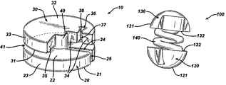
- FIG. 1 is a perspective view of a suture anchoring device constructed in accordance with an embodiment of the present invention, the device being shown in a configuration comprised of two disk-like retaining members.
- FIG. 2 is a perspective view of a suture anchoring device constructed in accordance with another embodiment, the device being shown in a configuration comprised of two dome-like retaining members and of a helical coupler.
- FIGS. 3 a to 3 d are schematic representations which illustrate the steps involved in the attachment of a suture to the suture anchoring device of FIG. 1 .
- the suture anchoring device described herein can be used in combination with multiple sutures or with a single suture for various types of surgical procedures by surgeons.
- the suture anchoring device may be fabricated from any biocompatible medical material, such as polymeric or metallic.
- the polymeric material may be absorbable within a mammalian body (e.g. polydioxanone such as poly(1,4-dioxan-2-one), polymers or copolymers of organic hydroxyesters, polyglycolide, polylactide, polyhydroxy butyric acid, polycaprolactone, polytrimethylene carbonate and polyvinyl alcohol), or it may be non-absorbable (e.g.
- the suture anchoring device may be fabricated via standard machining processes, injection molding, or a lithographic process (e.g. stereolithography).
- the suture anchoring device may be comprised in part of a first retaining member 20 having a first surface 21 , a second surface 22 and a first outer edge 23 that is connected in a parallel, non-coplanar fashion to a second retaining member 30 having a third surface 31 , a fourth surface 32 and a second outer edge 33 .
- the cross sectional area of the first retaining member taken in a plane parallel to the second surface may be substantially the same as, greater or less than the cross sectional area of the second retaining member taken in a parallel plane.
- First retaining member 20 is connected to the second retaining member 30 by a coupler 40 .
- First retaining member 20 contains a first opening 24 that may extend from the entrance 25 located at the first outer edge 23 to any point within the first retaining member up to the coupler 40 , and/or from the first surface 21 to the second surface 22 , while the second retaining member has a holding means for securing the suture in place. Furthermore, the second surface 22 and third surface 31 of retaining members 20 and 30 form the boundaries of a space 41 that resides between the two retaining members and about the coupler 40 . The width of this space is preferably as large as the diameter of the suture that is to be secured within the suture anchoring device. In one embodiment, second retaining member 30 may be comprised of a disk-like structure having one sector absent.
- second retaining member 30 is also comprised of a fifth surface 34 and a sixth surface 35 that lie nominally perpendicular to the third 31 and fourth 32 surfaces.
- a holding means comprised of a second opening 36 , originates on the fifth surface 34 and ends at a point within the second retaining member.
- the span of the entrance 37 of second opening 36 is less than the width of the rear wall 38 of second opening 36 .
- the width of second opening 36 is approximately the same size as the suture that is to be secured.
- a plane that coincides with the fifth surface 34 passes through the first opening 25 of the first retaining member 20 .
- the holding means may be comprised in part of a hook member upon fifth surface 34 in lieu of or in addition to second opening 36 to provide further stability to the portion of the excess suture immediately adjacent to the wrapped portion of the suture.
- the corners and edges of the suture anchoring device are rounded in order to minimize the possibility of damaging the suture during application of the device and to maximize the holding strength the device provides.
- all edges and corners of the device are rounded to prevent any sharp portions of device from cutting or pinching suture in a manner that will compromise its strength or integrity.
- FIG. 2 another embodiment of a suture locking device 100 is shown.
- This embodiment may be comprised in part of a first retaining member 120 having a first surface 121 and a second surface 122 that is connected in a parallel, non-coplanar fashion to a second retaining member 130 having a third surface 131 and a fourth surface 132 .
- First retaining member 120 is connected to second retaining member 130 by a coupler 140 .
- Coupler 140 may have a cylindrical cross section, such as a shaft, or a helical shape in order to provide a tortuous path for the suture as the suture is wound around the coupler. This tortuous path provides additional friction between the coupler and the suture to aid in stronger suture fixation.
- suture anchoring device 10 is used to secure suture 63 .
- tension is applied to suture 63 to place the suture into a taut state.
- Suture anchoring device 10 is then brought into contact with suture 63 such that the suture passes through first opening 24 on first retaining member 20 . Maintaining suture 63 within first opening 24 , suture anchoring device 10 is maneuvered to the sutured incision 82 on wound site 80 on the tissue surface. As shown in FIG. 3 b , suture 63 is then wrapped around coupler 40 by introducing the suture into space 41 between the second surface 22 and third surface 31 of the first and second retaining members and revolving the suture around the coupler 40 at least one time while maintaining the suture in a taut state. Introduction of suture 63 into space 41 may be facilitated by guiding the suture circumferentially away from the fifth surface 34 and circumferentially towards the sixth surface 35 .
- this holding means is merely to prevent suture 63 from unwrapping from around coupler 40 over time. This holding means does not resist the tendency of the suture 63 to slacken due to resilient forces of the wound site. Instead, the resilient forces of the wound site are counteracted by the internal friction within the suture anchoring device. This friction is created within the wrapped portion 65 of suture 63 , at the interface of wrapped portion 65 with coupler 40 , and at the interface of the second surface 22 and third surface 31 with suture 63 as shown in FIG. 3 d.
- the suture anchoring device may be used manually, i.e., applied by the surgeon using hands, or with any surgical instruments (e.g. laparoscopic instruments) suitable for suture manipulation, tissue manipulation, or the like.
- any surgical instruments e.g. laparoscopic instruments
- a laparoscopic device that is specifically designed to automate the anchoring method may be used.
Abstract
Description
Claims (22)
Priority Applications (1)
| Application Number | Priority Date | Filing Date | Title |
|---|---|---|---|
| US10/743,667 US7686830B2 (en) | 2003-12-22 | 2003-12-22 | Suture anchoring device |
Applications Claiming Priority (1)
| Application Number | Priority Date | Filing Date | Title |
|---|---|---|---|
| US10/743,667 US7686830B2 (en) | 2003-12-22 | 2003-12-22 | Suture anchoring device |
Publications (2)
| Publication Number | Publication Date |
|---|---|
| US20050149120A1 US20050149120A1 (en) | 2005-07-07 |
| US7686830B2 true US7686830B2 (en) | 2010-03-30 |
Family
ID=34710566
Family Applications (1)
| Application Number | Title | Priority Date | Filing Date |
|---|---|---|---|
| US10/743,667 Active 2027-01-22 US7686830B2 (en) | 2003-12-22 | 2003-12-22 | Suture anchoring device |
Country Status (1)
| Country | Link |
|---|---|
| US (1) | US7686830B2 (en) |
Cited By (19)
| Publication number | Priority date | Publication date | Assignee | Title |
|---|---|---|---|---|
| US20100004683A1 (en) * | 2007-12-31 | 2010-01-07 | Cayenne Medical, Inc. | Anchors and method for securing suture to bone |
| US20130226237A1 (en) * | 2012-02-27 | 2013-08-29 | Cook Medical Technologies Llc | Suture Clamp And Gastrointestinal Suture Anchor Set Device Using Same |
| US9107655B2 (en) | 2012-02-16 | 2015-08-18 | Cook Medical Technologies Llc | External suture securement devices and methods |
| US9393008B2 (en) | 2011-09-22 | 2016-07-19 | Cook Medical Technologies Llc | Suture clamp |
| WO2017014995A1 (en) * | 2015-07-17 | 2017-01-26 | JULVIA Technologies, Inc. | Suture locks |
| USD808778S1 (en) * | 2014-01-07 | 2018-01-30 | Limitless Innovations, Inc. | Multi-cable manager |
| USD811858S1 (en) * | 2016-12-16 | 2018-03-06 | Ipex Technologies Inc. | Grommet for a cable connector and a cable connector |
| USD821183S1 (en) * | 2014-06-12 | 2018-06-26 | Crestron Electronics, Inc. | Cable management hub |
| USD831467S1 (en) * | 2017-01-20 | 2018-10-23 | Detnet South Africa (Pty) Ltd | Spool |
| USD831469S1 (en) * | 2017-12-13 | 2018-10-23 | Ellis Patents Holdings Limited | Mount for a cable clamp |
| US20180317612A1 (en) * | 2015-11-06 | 2018-11-08 | Nifco Inc. | String fastener and string fastening device |
| US10141686B2 (en) | 2016-03-29 | 2018-11-27 | Ipex Technologies, Inc. | Grommet for a cable connector and a strain relief cable fitting having an insert |
| USD837636S1 (en) * | 2017-07-11 | 2019-01-08 | Theragun, LLC | Connector |
| USD842078S1 (en) * | 2016-11-24 | 2019-03-05 | Ipex Technologies Inc. | Oval grommet for a cable connector and a cable connector |
| USD867860S1 (en) * | 2018-12-26 | 2019-11-26 | Theragun, LLC | Connector |
| USD871194S1 (en) * | 2018-06-28 | 2019-12-31 | Hirata Corporation | Pad |
| US10709205B2 (en) * | 2017-03-13 | 2020-07-14 | Xpand Inc. | Shoe lace lock and system and method for lacing shoes |
| USD900596S1 (en) * | 2018-11-05 | 2020-11-03 | Cnh Industrial America Llc | Flexible hose clamp |
| GB2622797A (en) * | 2022-09-27 | 2024-04-03 | Osteoweld Surgical Ltd | Suture retainer and insertion tool |
Families Citing this family (12)
| Publication number | Priority date | Publication date | Assignee | Title |
|---|---|---|---|---|
| US7153325B2 (en) * | 2003-08-01 | 2006-12-26 | Ultra-Kinetics, Inc. | Prosthetic intervertebral disc and methods for using the same |
| US7674276B2 (en) * | 2006-10-06 | 2010-03-09 | Biomet Sports Medicine, Llc | Rotational securing of a suture |
| US20090062742A1 (en) * | 2007-08-31 | 2009-03-05 | John Anthony Rotella | Blunted Safety Needle |
| US7867253B2 (en) * | 2007-08-31 | 2011-01-11 | Kimberly-Clark Worldwide, Inc. | Suture retention hub |
| US8157816B2 (en) * | 2007-08-31 | 2012-04-17 | Kimberly-Clark Worldwide, Inc. | Gastropexy kit |
| US8945180B2 (en) * | 2010-09-08 | 2015-02-03 | Abbott Cardiovascular Systems, Inc. | Large hole closure device |
| US20140074161A1 (en) * | 2012-09-07 | 2014-03-13 | Mimosa Medical, Inc. | Wound closure devices and methods of use |
| US9566057B2 (en) * | 2012-12-12 | 2017-02-14 | Cook Medical Technologies Llc | Suture retention mechanism |
| JP6413160B2 (en) * | 2013-05-09 | 2018-10-31 | 泉工医科工業株式会社 | Suture lock member and suture needle set |
| US10245017B2 (en) | 2014-05-30 | 2019-04-02 | Biomet Manufacturing, Llc | Knotless twist suture anchor |
| US10098628B2 (en) | 2014-07-22 | 2018-10-16 | Cook Medical Technologies Llc | Anchor deployment system, device, and method of treatment |
| US10893861B2 (en) * | 2016-06-17 | 2021-01-19 | Lsi Solutions, Inc. | Surgical port for stay sutures |
Citations (18)
| Publication number | Priority date | Publication date | Assignee | Title |
|---|---|---|---|---|
| US1830014A (en) | 1931-03-28 | 1931-11-03 | Bemis Bro Bag Co | Fastener |
| US2075508A (en) | 1934-07-18 | 1937-03-30 | Edward W Davidson | Suture retainer |
| US2458252A (en) | 1944-01-20 | 1949-01-04 | Lloyd N Chatterton | Securing device |
| US3409014A (en) | 1965-10-08 | 1968-11-05 | Amp Inc | Surgical ligating disk having a noose forming ligature threaded therethrough |
| US3910281A (en) * | 1973-10-09 | 1975-10-07 | Bio Medicus Inc | Suture anchor |
| US4291698A (en) * | 1978-12-09 | 1981-09-29 | Intermedicat Gmbh | Button for surgical applications |
| US4823794A (en) * | 1982-07-12 | 1989-04-25 | Pierce William S | Surgical pledget |
| US4939820A (en) | 1989-01-03 | 1990-07-10 | Babcock Martin P | Rope fastener |
| US5474572A (en) | 1993-01-07 | 1995-12-12 | Hayhurst; John O. | Clip for suture |
| US5645553A (en) | 1994-08-29 | 1997-07-08 | United States Surgical Corporation | Suture clip applier |
| US6066160A (en) | 1998-11-23 | 2000-05-23 | Quickie Llc | Passive knotless suture terminator for use in minimally invasive surgery and to facilitate standard tissue securing |
| US6106545A (en) | 1998-04-16 | 2000-08-22 | Axya Medical, Inc. | Suture tensioning and fixation device |
| US6152935A (en) * | 1996-12-11 | 2000-11-28 | Ethicon, Inc. | Meniscal repair device having integral spring member |
| US6165204A (en) | 1999-06-11 | 2000-12-26 | Scion International, Inc. | Shaped suture clip, appliance and method therefor |
| US6432123B2 (en) | 1998-12-30 | 2002-08-13 | Ethicon, Inc. | Suture locking device |
| US6599311B1 (en) * | 1998-06-05 | 2003-07-29 | Broncus Technologies, Inc. | Method and assembly for lung volume reduction |
| US20040260344A1 (en) * | 2003-05-07 | 2004-12-23 | Anpa Medical, Inc. | Suture lock |
| US20050096699A1 (en) * | 2003-11-05 | 2005-05-05 | Applied Medical Resources Corporation | Suture securing device and method |
-
2003
- 2003-12-22 US US10/743,667 patent/US7686830B2/en active Active
Patent Citations (18)
| Publication number | Priority date | Publication date | Assignee | Title |
|---|---|---|---|---|
| US1830014A (en) | 1931-03-28 | 1931-11-03 | Bemis Bro Bag Co | Fastener |
| US2075508A (en) | 1934-07-18 | 1937-03-30 | Edward W Davidson | Suture retainer |
| US2458252A (en) | 1944-01-20 | 1949-01-04 | Lloyd N Chatterton | Securing device |
| US3409014A (en) | 1965-10-08 | 1968-11-05 | Amp Inc | Surgical ligating disk having a noose forming ligature threaded therethrough |
| US3910281A (en) * | 1973-10-09 | 1975-10-07 | Bio Medicus Inc | Suture anchor |
| US4291698A (en) * | 1978-12-09 | 1981-09-29 | Intermedicat Gmbh | Button for surgical applications |
| US4823794A (en) * | 1982-07-12 | 1989-04-25 | Pierce William S | Surgical pledget |
| US4939820A (en) | 1989-01-03 | 1990-07-10 | Babcock Martin P | Rope fastener |
| US5474572A (en) | 1993-01-07 | 1995-12-12 | Hayhurst; John O. | Clip for suture |
| US5645553A (en) | 1994-08-29 | 1997-07-08 | United States Surgical Corporation | Suture clip applier |
| US6152935A (en) * | 1996-12-11 | 2000-11-28 | Ethicon, Inc. | Meniscal repair device having integral spring member |
| US6106545A (en) | 1998-04-16 | 2000-08-22 | Axya Medical, Inc. | Suture tensioning and fixation device |
| US6599311B1 (en) * | 1998-06-05 | 2003-07-29 | Broncus Technologies, Inc. | Method and assembly for lung volume reduction |
| US6066160A (en) | 1998-11-23 | 2000-05-23 | Quickie Llc | Passive knotless suture terminator for use in minimally invasive surgery and to facilitate standard tissue securing |
| US6432123B2 (en) | 1998-12-30 | 2002-08-13 | Ethicon, Inc. | Suture locking device |
| US6165204A (en) | 1999-06-11 | 2000-12-26 | Scion International, Inc. | Shaped suture clip, appliance and method therefor |
| US20040260344A1 (en) * | 2003-05-07 | 2004-12-23 | Anpa Medical, Inc. | Suture lock |
| US20050096699A1 (en) * | 2003-11-05 | 2005-05-05 | Applied Medical Resources Corporation | Suture securing device and method |
Cited By (23)
| Publication number | Priority date | Publication date | Assignee | Title |
|---|---|---|---|---|
| US9295460B2 (en) * | 2007-12-31 | 2016-03-29 | Cayenne Medical, Inc. | Anchors and method for securing suture to bone |
| US20100004683A1 (en) * | 2007-12-31 | 2010-01-07 | Cayenne Medical, Inc. | Anchors and method for securing suture to bone |
| US9393008B2 (en) | 2011-09-22 | 2016-07-19 | Cook Medical Technologies Llc | Suture clamp |
| US9107655B2 (en) | 2012-02-16 | 2015-08-18 | Cook Medical Technologies Llc | External suture securement devices and methods |
| US9398904B2 (en) | 2012-02-16 | 2016-07-26 | Cook Medical Technologies Llc | External suture securement devices and methods |
| US20130226237A1 (en) * | 2012-02-27 | 2013-08-29 | Cook Medical Technologies Llc | Suture Clamp And Gastrointestinal Suture Anchor Set Device Using Same |
| US9084596B2 (en) * | 2012-02-27 | 2015-07-21 | Cook Medical Technologies Llc | Suture clamp and gastrointestinal suture anchor set device using same |
| USD808778S1 (en) * | 2014-01-07 | 2018-01-30 | Limitless Innovations, Inc. | Multi-cable manager |
| USD821183S1 (en) * | 2014-06-12 | 2018-06-26 | Crestron Electronics, Inc. | Cable management hub |
| WO2017014995A1 (en) * | 2015-07-17 | 2017-01-26 | JULVIA Technologies, Inc. | Suture locks |
| US20180317612A1 (en) * | 2015-11-06 | 2018-11-08 | Nifco Inc. | String fastener and string fastening device |
| US10141686B2 (en) | 2016-03-29 | 2018-11-27 | Ipex Technologies, Inc. | Grommet for a cable connector and a strain relief cable fitting having an insert |
| USD847612S1 (en) * | 2016-10-21 | 2019-05-07 | Ipex Technologies Inc. | Cable connector with a grommet and insert |
| USD842078S1 (en) * | 2016-11-24 | 2019-03-05 | Ipex Technologies Inc. | Oval grommet for a cable connector and a cable connector |
| USD811858S1 (en) * | 2016-12-16 | 2018-03-06 | Ipex Technologies Inc. | Grommet for a cable connector and a cable connector |
| USD831467S1 (en) * | 2017-01-20 | 2018-10-23 | Detnet South Africa (Pty) Ltd | Spool |
| US10709205B2 (en) * | 2017-03-13 | 2020-07-14 | Xpand Inc. | Shoe lace lock and system and method for lacing shoes |
| USD837636S1 (en) * | 2017-07-11 | 2019-01-08 | Theragun, LLC | Connector |
| USD831469S1 (en) * | 2017-12-13 | 2018-10-23 | Ellis Patents Holdings Limited | Mount for a cable clamp |
| USD871194S1 (en) * | 2018-06-28 | 2019-12-31 | Hirata Corporation | Pad |
| USD900596S1 (en) * | 2018-11-05 | 2020-11-03 | Cnh Industrial America Llc | Flexible hose clamp |
| USD867860S1 (en) * | 2018-12-26 | 2019-11-26 | Theragun, LLC | Connector |
| GB2622797A (en) * | 2022-09-27 | 2024-04-03 | Osteoweld Surgical Ltd | Suture retainer and insertion tool |
Also Published As
| Publication number | Publication date |
|---|---|
| US20050149120A1 (en) | 2005-07-07 |
Similar Documents
| Publication | Publication Date | Title |
|---|---|---|
| US7686830B2 (en) | Suture anchoring device | |
| US8728122B2 (en) | Suture anchoring device | |
| US7967841B2 (en) | Methods for using looped tissue-grasping devices | |
| US10292695B2 (en) | Surgical filament snare assemblies | |
| US5383905A (en) | Suture loop locking device | |
| US7335221B2 (en) | Suture anchoring and tensioning device and method for using same | |
| CA2772252C (en) | Barbed sutures having pledget stoppers and methods therefor | |
| US7678134B2 (en) | Knotless anchor for tissue repair | |
| US6652562B2 (en) | Suture anchoring and tensioning device | |
| AU670461B2 (en) | Endoscopic suturing device | |
| US8974495B2 (en) | Adjustable anchor systems and methods | |
| US20160345955A1 (en) | Systems and methods for repairing tissue | |
| US9539004B2 (en) | Collapsible locking suture | |
| JP2002538877A (en) | Self-supporting loop-free ligature suture anchor assembly | |
| KR102205586B1 (en) | Method and device for approximating tissue | |
| KR20180123273A (en) | Suture with hook and needle for suture and face lifting | |
| US11337687B2 (en) | Double row collapsible suture construct |
Legal Events
| Date | Code | Title | Description |
|---|---|---|---|
| AS | Assignment |
Owner name: ETHICON, INC.,NEW JERSEY Free format text: ASSIGNMENT OF ASSIGNORS INTEREST;ASSIGNORS:COLLIER, JOHN;NERING, ROBERT;NOZAD, IRENE;AND OTHERS;REEL/FRAME:015287/0206 Effective date: 20040421 Owner name: ETHICON, INC., NEW JERSEY Free format text: ASSIGNMENT OF ASSIGNORS INTEREST;ASSIGNORS:COLLIER, JOHN;NERING, ROBERT;NOZAD, IRENE;AND OTHERS;REEL/FRAME:015287/0206 Effective date: 20040421 |
|
| FEPP | Fee payment procedure |
Free format text: PAYOR NUMBER ASSIGNED (ORIGINAL EVENT CODE: ASPN); ENTITY STATUS OF PATENT OWNER: LARGE ENTITY |
|
| STCF | Information on status: patent grant |
Free format text: PATENTED CASE |
|
| FPAY | Fee payment |
Year of fee payment: 4 |
|
| MAFP | Maintenance fee payment |
Free format text: PAYMENT OF MAINTENANCE FEE, 8TH YEAR, LARGE ENTITY (ORIGINAL EVENT CODE: M1552) Year of fee payment: 8 |
|
| MAFP | Maintenance fee payment |
Free format text: PAYMENT OF MAINTENANCE FEE, 12TH YEAR, LARGE ENTITY (ORIGINAL EVENT CODE: M1553); ENTITY STATUS OF PATENT OWNER: LARGE ENTITY Year of fee payment: 12 |