US7700210B2 - Increasing thermal dissipation of fuel cell stacks under partial electrical load - Google Patents
Increasing thermal dissipation of fuel cell stacks under partial electrical load Download PDFInfo
- Publication number
- US7700210B2 US7700210B2 US11/125,267 US12526705A US7700210B2 US 7700210 B2 US7700210 B2 US 7700210B2 US 12526705 A US12526705 A US 12526705A US 7700210 B2 US7700210 B2 US 7700210B2
- Authority
- US
- United States
- Prior art keywords
- stacks
- fuel cell
- output power
- fuel
- stack
- Prior art date
- Legal status (The legal status is an assumption and is not a legal conclusion. Google has not performed a legal analysis and makes no representation as to the accuracy of the status listed.)
- Active, expires
Links
Images


Classifications
-
- H—ELECTRICITY
- H01—ELECTRIC ELEMENTS
- H01M—PROCESSES OR MEANS, e.g. BATTERIES, FOR THE DIRECT CONVERSION OF CHEMICAL ENERGY INTO ELECTRICAL ENERGY
- H01M8/00—Fuel cells; Manufacture thereof
- H01M8/24—Grouping of fuel cells, e.g. stacking of fuel cells
- H01M8/249—Grouping of fuel cells, e.g. stacking of fuel cells comprising two or more groupings of fuel cells, e.g. modular assemblies
-
- H—ELECTRICITY
- H01—ELECTRIC ELEMENTS
- H01M—PROCESSES OR MEANS, e.g. BATTERIES, FOR THE DIRECT CONVERSION OF CHEMICAL ENERGY INTO ELECTRICAL ENERGY
- H01M8/00—Fuel cells; Manufacture thereof
- H01M8/04—Auxiliary arrangements, e.g. for control of pressure or for circulation of fluids
- H01M8/04007—Auxiliary arrangements, e.g. for control of pressure or for circulation of fluids related to heat exchange
-
- H—ELECTRICITY
- H01—ELECTRIC ELEMENTS
- H01M—PROCESSES OR MEANS, e.g. BATTERIES, FOR THE DIRECT CONVERSION OF CHEMICAL ENERGY INTO ELECTRICAL ENERGY
- H01M8/00—Fuel cells; Manufacture thereof
- H01M8/04—Auxiliary arrangements, e.g. for control of pressure or for circulation of fluids
- H01M8/04298—Processes for controlling fuel cells or fuel cell systems
- H01M8/04313—Processes for controlling fuel cells or fuel cell systems characterised by the detection or assessment of variables; characterised by the detection or assessment of failure or abnormal function
- H01M8/04537—Electric variables
- H01M8/04604—Power, energy, capacity or load
- H01M8/04619—Power, energy, capacity or load of fuel cell stacks
-
- H—ELECTRICITY
- H01—ELECTRIC ELEMENTS
- H01M—PROCESSES OR MEANS, e.g. BATTERIES, FOR THE DIRECT CONVERSION OF CHEMICAL ENERGY INTO ELECTRICAL ENERGY
- H01M8/00—Fuel cells; Manufacture thereof
- H01M8/04—Auxiliary arrangements, e.g. for control of pressure or for circulation of fluids
- H01M8/04298—Processes for controlling fuel cells or fuel cell systems
- H01M8/04694—Processes for controlling fuel cells or fuel cell systems characterised by variables to be controlled
- H01M8/04746—Pressure; Flow
- H01M8/04753—Pressure; Flow of fuel cell reactants
-
- H—ELECTRICITY
- H01—ELECTRIC ELEMENTS
- H01M—PROCESSES OR MEANS, e.g. BATTERIES, FOR THE DIRECT CONVERSION OF CHEMICAL ENERGY INTO ELECTRICAL ENERGY
- H01M8/00—Fuel cells; Manufacture thereof
- H01M8/06—Combination of fuel cells with means for production of reactants or for treatment of residues
- H01M8/0606—Combination of fuel cells with means for production of reactants or for treatment of residues with means for production of gaseous reactants
- H01M8/0612—Combination of fuel cells with means for production of reactants or for treatment of residues with means for production of gaseous reactants from carbon-containing material
- H01M8/0625—Combination of fuel cells with means for production of reactants or for treatment of residues with means for production of gaseous reactants from carbon-containing material in a modular combined reactor/fuel cell structure
-
- H—ELECTRICITY
- H01—ELECTRIC ELEMENTS
- H01M—PROCESSES OR MEANS, e.g. BATTERIES, FOR THE DIRECT CONVERSION OF CHEMICAL ENERGY INTO ELECTRICAL ENERGY
- H01M8/00—Fuel cells; Manufacture thereof
- H01M8/24—Grouping of fuel cells, e.g. stacking of fuel cells
- H01M8/241—Grouping of fuel cells, e.g. stacking of fuel cells with solid or matrix-supported electrolytes
- H01M8/2425—High-temperature cells with solid electrolytes
- H01M8/2432—Grouping of unit cells of planar configuration
-
- H—ELECTRICITY
- H01—ELECTRIC ELEMENTS
- H01M—PROCESSES OR MEANS, e.g. BATTERIES, FOR THE DIRECT CONVERSION OF CHEMICAL ENERGY INTO ELECTRICAL ENERGY
- H01M8/00—Fuel cells; Manufacture thereof
- H01M8/24—Grouping of fuel cells, e.g. stacking of fuel cells
- H01M8/241—Grouping of fuel cells, e.g. stacking of fuel cells with solid or matrix-supported electrolytes
- H01M8/244—Grouping of fuel cells, e.g. stacking of fuel cells with solid or matrix-supported electrolytes with matrix-supported molten electrolyte
-
- H—ELECTRICITY
- H01—ELECTRIC ELEMENTS
- H01M—PROCESSES OR MEANS, e.g. BATTERIES, FOR THE DIRECT CONVERSION OF CHEMICAL ENERGY INTO ELECTRICAL ENERGY
- H01M8/00—Fuel cells; Manufacture thereof
- H01M8/10—Fuel cells with solid electrolytes
- H01M8/12—Fuel cells with solid electrolytes operating at high temperature, e.g. with stabilised ZrO2 electrolyte
- H01M2008/1293—Fuel cells with solid oxide electrolytes
-
- H—ELECTRICITY
- H01—ELECTRIC ELEMENTS
- H01M—PROCESSES OR MEANS, e.g. BATTERIES, FOR THE DIRECT CONVERSION OF CHEMICAL ENERGY INTO ELECTRICAL ENERGY
- H01M8/00—Fuel cells; Manufacture thereof
- H01M8/14—Fuel cells with fused electrolytes
- H01M2008/147—Fuel cells with molten carbonates
-
- H—ELECTRICITY
- H01—ELECTRIC ELEMENTS
- H01M—PROCESSES OR MEANS, e.g. BATTERIES, FOR THE DIRECT CONVERSION OF CHEMICAL ENERGY INTO ELECTRICAL ENERGY
- H01M8/00—Fuel cells; Manufacture thereof
- H01M8/18—Regenerative fuel cells, e.g. redox flow batteries or secondary fuel cells
- H01M8/184—Regeneration by electrochemical means
-
- Y—GENERAL TAGGING OF NEW TECHNOLOGICAL DEVELOPMENTS; GENERAL TAGGING OF CROSS-SECTIONAL TECHNOLOGIES SPANNING OVER SEVERAL SECTIONS OF THE IPC; TECHNICAL SUBJECTS COVERED BY FORMER USPC CROSS-REFERENCE ART COLLECTIONS [XRACs] AND DIGESTS
- Y02—TECHNOLOGIES OR APPLICATIONS FOR MITIGATION OR ADAPTATION AGAINST CLIMATE CHANGE
- Y02E—REDUCTION OF GREENHOUSE GAS [GHG] EMISSIONS, RELATED TO ENERGY GENERATION, TRANSMISSION OR DISTRIBUTION
- Y02E60/00—Enabling technologies; Technologies with a potential or indirect contribution to GHG emissions mitigation
- Y02E60/30—Hydrogen technology
- Y02E60/50—Fuel cells
Definitions
- the present invention is generally directed to fuel cells and more specifically to fuel cell systems and their operation.
- Fuel cells are electrochemical devices which can convert energy stored in fuels to electrical energy with high efficiencies.
- High temperature fuel cells include solid oxide and molten carbonate fuel cells. These fuel cells may operate using hydrogen and/or hydrocarbon fuels.
- an oxidizing flow is passed through the cathode side of the fuel cell while a fuel flow is passed through the anode side of the fuel cell.
- the oxidizing flow is typically air, while the fuel flow is typically a hydrogen-rich gas created by reforming a hydrocarbon fuel source.
- the fuel cell operating at a typical temperature between 750° C. and 950° C., enables the transport of negatively charged oxygen ions from the cathode flow stream to the anode flow stream, where oxygen from oxygen ions combines with either free hydrogen or hydrogen in a hydrocarbon molecule to form water vapor and/or with carbon monoxide to form carbon dioxide.
- the excess electrons from the negatively charged ion are routed back to the cathode side of the fuel cell through an electrical circuit completed between anode and cathode, resulting in an electrical current flow through the circuit.
- a number of cells are connected in series forming a cell “stack.”
- Cells connected in series operate at the same current and are thereby locked to the same operating state.
- these fuel cells in the stack have to be maintained at or near their nominal or designed operating temperature.
- the fuel cells are usually designed to operate at a high or even a maximum load at which the fuel cells achieve the nominal or designed operating temperature.
- high temperature fuel cell stacks dissipate enough heat to maintain their nominal or designed operating temperature (provided adequate thermal management/insulation).
- the fuel cells operate at a partial or low load, which is lower than the designed high or maximum operating load. This may occur when there is low power demand on the fuel cell stack, for example.
- a drop in operating temperature may be acceptable, but at lower temperature the stack has reduced power generation capabilities and may be unable to provide sufficient power when the power demand increases suddenly.
- One aspect of present invention provides a method of operating a high temperature fuel cell system containing a plurality of fuel cell stacks.
- the method comprises operating one or more of the plurality of fuel cell stacks at a first output power while operating another one or more of the plurality of the fuel cell stacks at a second output power different from the first output power.
- FIG. 1 is a plot of voltage, electrical power density, and heat dissipated versus current for a fuel cell.
- FIG. 2 is a plot of electrical power density versus heat dissipated.
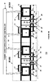
- FIGS. 3A and 3B are schematic side cross sectional views of systems of the embodiments of the present invention.
- FIGS. 4A and 5A are top cross sectional views of portions of the system of FIG. 3B .
- FIGS. 4B and 5B are side cross sectional views of portions of the system of FIG. 3B which correspond to the portions shown in FIGS. 4A and 5A , respectively.
- FIG. 6A is a top cross sectional view of a portion of the system of FIG. 3A .
- FIG. 6B is a side cross sectional view of a portion of the system of FIG. 3A , which corresponds to the portion shown in FIG. 6A .
- a software program is used to determine the optimum distribution of output powers of the stacks in the system.
- the corresponding heat dissipation data for each output power of each stack i.e., data similar to that shown in FIG. 2
- the program solves an optimization equation to determine the preferred output power for stack to obtain the desired or required heat dissipation.
- separate power conversion equipment connection and preferably separate fuel supplies are provided for every stack in order to increase the thermal dissipation by operating different stacks at different output power.
- a separate fuel inlet conduit and a separate fuel flow control device is provided for each stack. The amount of fuel being provided into each stack is controlled in coordination with the output power of the stacks. Thus, less fuel is provided into the stacks that are operating at lower output power than into the stacks that are operating at higher output power to avoid wasting fuel.
- the increased thermal dissipation is obtained without utilizing separate fuel feed conduits and controllers for each stack.
- a difference in time response between the electrical and the fuel (i.e., gas) subsystems is exploited.
- the load on the stacks is varied at a rate much faster than time constants involved in the (local) fuel transport to multiple stacks.
- multiple fuel cell stacks can operate at different output power levels on a common fuel supply while subject to load changes.
- the change in current occurs fast enough to avoid local fuel or oxidizer starvation of the cells in the stack. This may require load variations in the kHz regime or higher.
- the output power of the stacks in varied faster than the time it takes for local fuel or oxidizer starvation of the cells in the stack to set in.
- the first stack is operated at a higher output power and the second stack is operated at a lower power for a short period of time (i.e., for a period of time shorter than the time it takes for local fuel or oxidizer starvation of the cells in the stack to set in).
- the output power of the stacks is switched, such that the first stack is operated at a lower power and the second stack is operated at a higher power for a short period of time (i.e., for a period of time shorter than the time it takes for local fuel or oxidizer starvation of the cells in the stack to set in).
- the output power of the stacks is changed again such that the first stack is again operated at a higher output power and the second stack is again operated at a lower power for a short period of time.
- the load on the stacks is switched or alternated frequently, for example, at least once every one thousandths of a second (i.e., with a load variation frequency of 1 kHz or higher) to avoid local fuel or oxidizer starvation of the cells.
- a plurality of fuel cell stacks comprise at least a first set of fuel cell stacks containing one or more first stacks and a second set of fuel cell stacks containing one or more second stacks.
- the same amount of fuel is provided to each of the one or more first fuel cell stacks and to each of the one or more second fuel cell stacks.
- the load on the first and the second sets of stacks is repeatedly varied such that the output power of the first is alternately higher or lower than the output power of second sets of stacks.
- the output power/load switching is preferably conducted by an automated controller, such as a computer or logic circuit.
- software or hardware may be used to determine an optimum switching frequency and output power for the system.
- load modulations can be executed with a constant net stack output.
- a separate inverter dedicated to each stack or each set of stacks may be provided.
- the net output of the stacks may fluctuate.
- the energy storage required to level the stack output is small and can easily be provided by one or more capacitors or batteries which may already be a part of the system.
- one or more capacitors and/or batteries can be used to store excess energy generated during output power spikes and then release the stored energy during output power dips to provide a substantially even power output from the system.
- the stack load modulations may include reversed current operation of one or more stacks (i.e., reversing a polarity of current provided to the stacks).
- the stacks may be temporarily operated in the so-called electrolysis mode, where the stacks draw electrical energy from the power conditioning system rather than provide electrical energy to the power conditioning system.
- These temporary current inversions on fuel cells may reduce cell degradation and thereby increase performance.
- a suitable reducing or inert atmosphere is provided to the fuel cell fuel (i.e., anode) electrodes
- the cermet in the fuel electrodes may be reduced during the current inversions to improve the operation of the fuel cells.
- the fuel electrode cermets include nickel and yttria stabilized zirconia containing cermets and examples of a reducing or inert atmosphere include nitrogen, hydrogen or argon.
- an output power of one or more stacks is periodically cycled (i.e., varied) above and below an average desired or required output power, such that the output power substantially equals the average desired or required output power over a period of time.
- the fuel cell stacks need not be thermally integrated with other stacks (i.e., the fuel cell stacks may be thermally isolated from other stacks).
- only one stack may be used instead of a plurality of stacks.
- electrical energy is stored and released in an energy storage device, such as one or more capacitors and batteries.
- the electrical energy is stored in a storage device when the stack output power is above the average total desired or required output power.
- the stored electrical energy is released from the storage device when the output power is below the average total desired or required output power.
- the system of this embodiment comprises a plurality of solid oxide fuel cell stacks.
- the output power of each of the plurality of solid oxide fuel cell stacks is periodically cycled above and below an average desired or required output power at the same time.
- all of the stacks in this embodiment are either at a high or low output power at the same time.
- the combined thermal dissipation of the plurality of the stacks is still higher compared to the thermal dissipation of the plurality of the stacks operated at a constant output power over the period of time.
- the same power controller/power conditioning system may be used to operate all of the stacks. Furthermore, the same amount of fuel may be supplied to all of the stacks in the system.
- the system design is simplified since only one power controller/power conditioning system and one fuel supply control device is needed for the whole system.
- the fuel supply control device controls the supply of fuel to provide a lower amount of fuel to the stacks during low output power part of the cycle than during a high output power part of the cycle.
- an oxidizer supply control device such as an air blower or valve, controls the supply of oxidizer, such as air, to provide a lower amount of oxidizer to the stacks during low output power part of the cycle than during a high output power part of the cycle.
- the output power cycle frequency may range from high to low cycle frequency.
- the cycle frequency may range from several output power variations per second, such as 2-20 variations per second, to one output power variation per one or more seconds, such as one variation per 1-60 seconds, to one output power variation per one or more minutes, such as one variation per 1-120 minutes, for example, one variation per 1 to 10 minutes.
- each high and low output power duration may last less than a second, several seconds, several minutes or even one or more hours.
- SOFC stacks generally have significant thermal inertia and the operating temperature can in certain cases be allowed to drift slightly up or down, such as by a few degrees, such as 5-20 degrees C., up to 100 C up or down. If one or more stacks are cycled between low and high load to match an average load the stack, then thermal dissipation will increase.
- the output power cycling is preferably not done in response to a different output power demand by the power consumer (i.e., a stand alone device or the power grid) which receives power from the fuel cell system.
- the power consumer i.e., a stand alone device or the power grid
- the fuel cell system output power is intentionally cycled above and below the output power (i.e., the average power) actually desired or required by the power consumer.
- the energy storage device is used to provide a substantially constant output power to the power consumer such that the consumer does not notice the output power cycling by the fuel cell system.
- the power consumer can receive power from both the fuel cell system and the energy storage device.
- FIG. 3A illustrates a fuel cell system 1 according to a first preferred embodiment of the invention in which separate fuel inlet conduits and fuel controllers are used for different fuel cells.
- the system 1 is a high temperature fuel cell stack system, such as a solid oxide fuel cell (SOFC) system or a molten carbonate fuel cell system.
- SOFC solid oxide fuel cell
- the system 1 may be a regenerative system, such as a solid oxide regenerative fuel cell (SORFC) system which operates in both fuel cell (i.e., discharge) and electrolysis (i.e., charge) modes or it may be a non-regenerative system which only operates in the fuel cell mode.
- SORFC solid oxide regenerative fuel cell
- the system 1 contains a plurality of high temperature fuel cell stacks 3 .
- Each of the stacks 3 may contain a plurality of SOFCs, SORFCs or molten carbonate fuel cells.
- Each fuel cell contains an electrolyte, an anode electrode on one side of the electrolyte in an anode chamber, a cathode electrode on the other side of the electrolyte in a cathode chamber, as well as other components, such as separator plates/electrical contacts, seals, fuel cell housing and insulation.
- the oxidizer such as air or oxygen gas
- the fuel such as hydrogen and/or hydrocarbon fuel
- Any suitable fuel cell designs and component materials may be used.
- the system 1 also preferably contains a plurality of reformers 9 and combustors 15 .
- the reformers and/or combustors may be omitted.
- the reformers and combustors may be omitted.
- Each reformer 9 is adapted to reform a hydrocarbon fuel to a hydrogen containing reaction product and to provide the reaction product to a fuel cell stack 3 .
- Each combustor 15 is preferably thermally integrated with one or more of the plurality of the reformers 9 to provide heat to the reformers 9 .
- the term “thermally integrated” in this context means that the heat from the reaction in the combustor 15 drives the net endothermic fuel reformation in one or more reformers 9 .
- Humidified fuel is provided in each reformer through a respective fuel inlet conduit 23 .
- the system 1 also contains one or more control devices 24 adapted to independently control an amount of fuel being provided to each reformer 9 through each fuel inlet conduit 23 in response to the load on each associate stack 3 .
- the one or more control devices 24 may comprise one or more flow controllers, such as fuel flow control valves, that are adapted to control fuel flow into each fuel inlet conduit.
- each flow controller valve 24 is located in each of the plurality of the fuel inlet conduits 23 .
- the valves 24 may be controlled manually by an operator or automatically controlled by a control system, such as a computer or another electronic control system.
- a single, centrally located flow control device such as a multi-outlet valve, may be used to independently control the fuel flow into each of the fuel inlet conduits 23 from one or more fuel supply conduits 30 or fuel vessels.
- Each reformer 9 is operatively connected to a respective stack 3 anode inlet via a conduit 17 to provide a reformed product or fuel into each stack 3 .
- Air is provided into each stack 3 through a cathode inlet 19 .
- the cathode exhaust outlet 10 of each fuel cell stack 3 is preferably operatively connected to an inlet 25 of at least one combustor 15 to provide an oxidizer, such as hot air, into the combustor 15 .
- operatively connected means that components which are operatively connected may be directly or indirectly connected to each other.
- two components may be directly connected to each other by a fluid (i.e., gas and/or liquid) conduit.
- two components may be indirectly connected to each other such that a fluid stream passes between the first component to the second component through one or more additional components of the system.
- Each of a plurality of hydrocarbon fuel sources or feed conduits 27 is also operatively connected to a respective combustor 15 inlet 25 .
- each inlet 25 of each combustor 15 is connected to a separate hydrocarbon fuel source or feed conduit 27 .
- the fuel may be provided directly into the fuel cell.
- the conduits 24 and 27 may be connected to the same fuel supply conduit 30 or vessel, or the conduits 24 , 27 may be connected to different fuel supply conduits or vessels. Thus, the same or different fuel may be provided to the reformers 9 and combustors 15 , as desired.
- the system 1 may also optionally contain one or more control devices 29 adapted to independently control an amount of fuel being provided to each combustor through each fuel feed conduit 27 to independently control a temperature of each combustor 15 .
- the independent control of a temperature of each combustor 15 provides independent control of an amount of heat provided to each thermally integrated reformer 9 , which in turn provides an independent control of a temperature of each thermally integrated reformer 9 .
- the independent control of a temperature of each reformer 9 provides independent control of a temperature of each associated stack 3 which receives the reaction product from the controlled reformer 9 .
- the temperature of each associated reformer 9 and stack 3 may also be independently controlled.
- the one or more control devices 29 may comprise one or more flow controllers, such as fuel flow control valves, that are adapted to control fuel flow into each fuel feed conduit 27 , similar to valves 24 .
- One or more sensors may be located in the system 1 which are used to determine if one or more reformers 9 require additional heat and/or how much additional heat is required. These sensors may be reformer temperature sensor(s) which measure the reformer temperature and/or process parameter sensor(s), which measure one or more of fuel utilization, stack efficiency, heat loss and stack failure/turndown.
- the output of the sensor(s) is provided to a computer or other processor and/or is displayed to an operator to determine if and/or how much additional heat is required by each reformer.
- the processor or operator then independently controls each combustor's heat output based on the step of determining to provide a desired amount heat from the controlled combustor to the desired reformer.
- the stacks 3 are electrically connected to a power system 51 comprising a power conditioning and/or control subsystems via separate electrical connections 53 , such as via separate wires.
- the system 51 may comprise any suitable power conditioning subsystem which conditions electrical power received from the fuel cell stacks.
- the system 51 also comprises an electrical controller or controllers which control the load on the stacks 3 and the power output generated by the stacks 3 .
- the power conditioning and control functions may be provided by separate components.
- the system 51 may comprise separate power conditioning and/or control subsystems for each stack 3 .
- each fuel reformer 9 is thermally integrated with one or more of the fuel cell stacks 3 to support the endothermic reaction in the reformer 9 and to cool the stack or stacks 3 .
- thermally integrated in this context means that the heat from the reaction in the fuel cell stack 3 drives the net endothermic fuel reformation in the fuel reformer 9 .
- the fuel reformer 9 may be thermally integrated with one or more fuel cell stacks 3 by placing the reformer and stack(s) in the same hot box 31 and/or in thermal contact with each other, or by providing a thermal conduit or thermally conductive material which connects the stack(s) to the reformer.
- a plurality of units 200 and 201 / 202 may be located in the same hot box 31 in order to operate different stacks 3 at a different output power to transfer heat from stacks operating at a higher output power to the stacks operating at a lower output power.
- each unit 201 / 202 may be located in a separate hot box 31 , with the two fuel cell stacks 3 in each unit operating at a different output power. The details of each unit 200 , 201 and 202 will be described in more detail below with respect to FIGS. 4 , 5 and 6 .
- FIGS. 4-6 illustrate three exemplary configurations of one of a plurality of stack, reformer and combustor units of FIGS. 3A and 3B in the hot box 31 .
- the reformer 9 and combustor 15 shown in FIGS. 4-6 preferably comprise vessels, such as fluid conduits, that contain suitable catalysts for SMR reaction and combustion, respectively.
- the reformer 9 and combustor 15 may have gas conduits packed with catalysts and/or the catalysts may be coated on the walls of the reformer 9 and/or the combustor 15 .
- the reformer 9 and combustor 15 unit can be of cylindrical type, as shown in FIG. 4A or plate type as shown in FIGS. 5A and 6A .
- the plate type unit provides more surface area for heat transfer while the cylindrical type unit is cheaper to manufacture.
- the reformer 9 and combustor 15 are integrated into the same enclosure 31 and more preferably share at least one wall, as shown in FIGS. 4-6 .
- the reformer 9 and combustor 15 are thermally integrated with the stack(s) 3 , and may be located in the same enclosure or hot box 31 , but comprise separate vessels from the stack(s) 3 (i.e., external reformer configuration).
- FIGS. 4A and 4B show the cross-sectional top and front views, respectively, of one of a plurality of units 201 shown in FIG. 3B .
- Each unit 201 contains two stacks 3 , and a cylindrical reformer 9 /combustor 15 subunit 210 .
- fins 209 are provided in the stack cathode exhaust conduit 10 and in the combustor 15 combustion zone 207 to assist with convective heat transfer to the reformer 9 .
- the fins are provided on the external surfaces of the wall(s) of the reformer.
- each stack 3 contains an oxidizer (i.e., air) inlet conduit 19 , a fuel or anode inlet conduit 223 and a fuel or anode exhaust conduit 225 .
- oxidizer i.e., air
- the combustion zone 207 of the combustor 15 is located in the core of the cylindrical reformer 9 .
- the combustor 15 comprises a catalyst containing channel bounded by the inner wall 211 of the reformer 9 .
- the combustion zone 207 is also the channel for the cathode exhaust gas.
- the space 215 between the stacks 3 and the outer wall 213 of the reformer 9 comprises the upper portion of the stack cathode exhaust conduit 10 .
- the reformer inner wall 211 is the outer wall of the combustor 15 and the reformer outer wall 213 is the inner wall of the upper portion of stack cathode exhaust conduit 10 .
- a cathode exhaust opening 217 can be located in the enclosure 31 to connect the upper portion 215 of conduit 10 with the lower portions of the conduit 10 .
- the enclosure 31 may comprise any suitable container and preferably comprises a thermally insulating material.
- FIGS. 5A and 5B show the cross-sectional top and front views, respectively, of an alternative unit 202 containing two stacks 3 and a plate type reformer 9 coupled with a plate type combustor 15 .
- each combustor is thermally integrated with two reformers.
- the configuration of the plate type reformer-combustor subunit 220 is the same as the cylindrical reformer-combustor subunit 210 shown in FIGS. 4A and 4B , except that the reformer-combustor subunit 220 is sandwich shaped between the stacks.
- the combustion zone 207 is a channel having a rectangular cross sectional shape which is located between two reformer 9 portions.
- the reformer 9 portions comprise channels having a rectangular cross sectional shape.
- each unit 201 and 202 contains two stacks 3 , one combustor 15 and one or two reformers 9 , respectively.
- FIGS. 6A and 6B show the cross-sectional top and front views, respectively, of one of a plurality of units 200 shown in FIG. 3A .
- the unit 200 contains one stack 3 and a plate type reformer 9 coupled with a plate type combustor 15 .
- each combustor is thermally integrated with one reformer.
- Exhaust gas is wrapped around the reformer 9 from one side.
- One side of the combustion zone 207 channel faces insulation of the container or hot box 31 or the stacks of adjacent unit 200 while the other side faces the reformer 9 inner wall 211 .
- each unit 200 contains a single stack 3 , reformer 9 and combustor 15 .
- FIGS. 3A and 3B A method of operating the system 1 according to a first preferred embodiment of the present invention is described with reference to FIGS. 3A and 3B .
- the power conditioning/control system 51 independently controls the load on the stacks 3 and the output power of the stacks 3 .
- the preheated hydrocarbon fuel inlet stream and steam enter each one of the reformers 9 through separately controlled inlet conduits 23 where the fuel is reformed into a reformate (i.e., a hydrogen and carbon containing gas).
- the valves 24 control the amount of fuel provided to each reformer 9 based on the load and output power of each stack 3 which receives the reformed fuel from each reformer 9 .
- the reformed fuel i.e., reformate
- the stack anode exhaust stream exists the anode outlet 225 of the stack 3 and may be provided to a heat exchanger where it preheats a stream being provided into one or more stacks 3 .
- a preheated air inlet stream is provided into the cathode inlet 19 of each of the stacks 3 .
- the air then exits the stack 3 as a cathode exhaust stream and wraps around one or more reformers 9 .
- the cathode exhaust stream then enters the combustion zone of the combustor 15 through conduit 10 via opening 217 and inlet 25 .
- the system 1 is preferably configured such that the cathode exhaust (i.e., hot air) exits on the same side of the system as the inlet of the reformer 9 .
- the cathode exhaust i.e., hot air
- the mass flow of hot cathode exhaust is the maximum at the lower end of the device, it supplies the maximum heat where it is needed, at feed point of the reformer 9 (i.e., the lower portion of the reformer shown in FIG. 4B ).
- the mass flow of the hot air exiting the stack is maximum adjacent to the lower portion of the reformer 9 where the most heat is needed.
- the cathode exhaust and reformer inlet may be provided in other locations.
- Desulfurized natural gas or another hydrocarbon fuel is also supplied from the fuel feed conduits 27 into the inlets 25 of the combustors 15 .
- Natural gas is injected into the central combustion zone 207 of the combustor 15 where it mixes with the hot cathode exhaust.
- the circular or spiral fins are preferably attached to the inner 211 and outer 213 reformer walls to assist heat transfer. Heat is transferred to the outer wall 213 of the reformer 9 from the stack 3 by convection and radiation. Heat is transferred to the inner wall 211 of the reformer by convection and/or conduction from the combustion zone 207 .
- the reformer and combustion catalysts can either be coated on the walls or packed in respective flow channels.
- the exhaust stream from each of the combustors 15 then preferably enters a heat exchanger where it exchanges heat with an incoming stream being provided to one or more stacks 3 .
Abstract
Description
τelectrical<<τfluid (1)
Claims (10)
Priority Applications (3)
| Application Number | Priority Date | Filing Date | Title |
|---|---|---|---|
| US11/125,267 US7700210B2 (en) | 2005-05-10 | 2005-05-10 | Increasing thermal dissipation of fuel cell stacks under partial electrical load |
| US12/591,872 US8685579B2 (en) | 2005-05-10 | 2009-12-03 | Increasing thermal dissipation of fuel cell stacks under partial electrical load |
| US14/187,546 US9166246B2 (en) | 2005-05-10 | 2014-02-24 | Increasing thermal dissipation of fuel cell stacks under partial electrical load |
Applications Claiming Priority (1)
| Application Number | Priority Date | Filing Date | Title |
|---|---|---|---|
| US11/125,267 US7700210B2 (en) | 2005-05-10 | 2005-05-10 | Increasing thermal dissipation of fuel cell stacks under partial electrical load |
Related Child Applications (1)
| Application Number | Title | Priority Date | Filing Date |
|---|---|---|---|
| US12/591,872 Division US8685579B2 (en) | 2005-05-10 | 2009-12-03 | Increasing thermal dissipation of fuel cell stacks under partial electrical load |
Publications (2)
| Publication Number | Publication Date |
|---|---|
| US20060257696A1 US20060257696A1 (en) | 2006-11-16 |
| US7700210B2 true US7700210B2 (en) | 2010-04-20 |
Family
ID=37419484
Family Applications (3)
| Application Number | Title | Priority Date | Filing Date |
|---|---|---|---|
| US11/125,267 Active 2028-10-04 US7700210B2 (en) | 2005-05-10 | 2005-05-10 | Increasing thermal dissipation of fuel cell stacks under partial electrical load |
| US12/591,872 Active 2028-05-18 US8685579B2 (en) | 2005-05-10 | 2009-12-03 | Increasing thermal dissipation of fuel cell stacks under partial electrical load |
| US14/187,546 Active US9166246B2 (en) | 2005-05-10 | 2014-02-24 | Increasing thermal dissipation of fuel cell stacks under partial electrical load |
Family Applications After (2)
| Application Number | Title | Priority Date | Filing Date |
|---|---|---|---|
| US12/591,872 Active 2028-05-18 US8685579B2 (en) | 2005-05-10 | 2009-12-03 | Increasing thermal dissipation of fuel cell stacks under partial electrical load |
| US14/187,546 Active US9166246B2 (en) | 2005-05-10 | 2014-02-24 | Increasing thermal dissipation of fuel cell stacks under partial electrical load |
Country Status (1)
| Country | Link |
|---|---|
| US (3) | US7700210B2 (en) |
Cited By (2)
| Publication number | Priority date | Publication date | Assignee | Title |
|---|---|---|---|---|
| US20100248049A1 (en) * | 2009-03-26 | 2010-09-30 | Bloom Energy Corporation | Fuel cell system with interruption control |
| US9093674B2 (en) | 2008-08-21 | 2015-07-28 | Ceres Intellectual Property Company Limited | Fuel cell stack flow hood air flow using an air distribution device |
Families Citing this family (17)
| Publication number | Priority date | Publication date | Assignee | Title |
|---|---|---|---|---|
| EA015917B1 (en) | 2007-02-27 | 2011-12-30 | Серес Интеллекчуал Проперти Компани Лимитед | Fuel cell stack flow hood |
| US7964314B2 (en) * | 2007-10-30 | 2011-06-21 | Corning Incorporated | Segmented solid oxide fuel cell stack and methods for operation and use thereof |
| DE112009003594T5 (en) * | 2008-12-12 | 2012-05-24 | Ezelleron Gmbh | Fuel cell system with reformer |
| US8889306B2 (en) * | 2010-02-16 | 2014-11-18 | The Boeing Company | Modularized electrochemical cell system |
| JP5738983B2 (en) * | 2010-05-05 | 2015-06-24 | ハルドール・トプサー・アクチエゼルスカベット | How to operate a high temperature fuel cell stack |
| US9190673B2 (en) * | 2010-09-01 | 2015-11-17 | Bloom Energy Corporation | SOFC hot box components |
| JP5744349B2 (en) * | 2013-05-23 | 2015-07-08 | 京セラ株式会社 | Fuel cell module and fuel cell device |
| JP6111904B2 (en) * | 2013-07-03 | 2017-04-12 | 株式会社デンソー | Fuel cell device |
| KR102063947B1 (en) * | 2013-12-27 | 2020-01-08 | 에스케이이노베이션 주식회사 | Device for controlling fuel cell heating value |
| US10320015B1 (en) | 2014-03-07 | 2019-06-11 | The United States Of America As Represented By The Administrator Of National Aeronautics And Space Administration | Fuel Cell Power Management |
| JP6605884B2 (en) * | 2014-09-02 | 2019-11-13 | 株式会社東芝 | Hydrogen production system and hydrogen production method |
| DE102014226082A1 (en) * | 2014-12-16 | 2016-06-16 | Robert Bosch Gmbh | fuel cell device |
| DE102016220371A1 (en) * | 2016-10-18 | 2018-04-19 | Robert Bosch Gmbh | Fuel cell device and method of manufacturing a fuel cell device |
| JP7081391B2 (en) * | 2018-08-24 | 2022-06-07 | トヨタ自動車株式会社 | Fuel cell system |
| JP7087827B2 (en) | 2018-08-24 | 2022-06-21 | トヨタ自動車株式会社 | Fuel cell system |
| EP3844835B1 (en) * | 2018-08-29 | 2024-01-10 | Watt Fuel Cell Corp. | Thermally insulated housing for a heat-producing, heat-radiating device |
| CN110808387A (en) * | 2019-10-21 | 2020-02-18 | 深圳市氢蓝时代动力科技有限公司 | Gas supply method of hydrogen fuel cell, hydrogen fuel cell and engine |
Citations (47)
| Publication number | Priority date | Publication date | Assignee | Title |
|---|---|---|---|---|
| US4041210A (en) | 1976-08-30 | 1977-08-09 | United Technologies Corporation | Pressurized high temperature fuel cell power plant with bottoming cycle |
| US4182795A (en) | 1978-07-10 | 1980-01-08 | Energy Research Corporation | Fuel cell thermal control and reforming of process gas hydrocarbons |
| US4792502A (en) | 1986-11-14 | 1988-12-20 | International Fuel Cells Corporation | Apparatus for producing nitrogen |
| US4898792A (en) | 1988-12-07 | 1990-02-06 | Westinghouse Electric Corp. | Electrochemical generator apparatus containing modified high temperature insulation and coated surfaces for use with hydrocarbon fuels |
| US4917971A (en) | 1989-03-03 | 1990-04-17 | Energy Research Corporation | Internal reforming fuel cell system requiring no recirculated cooling and providing a high fuel process gas utilization |
| US4983471A (en) | 1989-12-28 | 1991-01-08 | Westinghouse Electric Corp. | Electrochemical cell apparatus having axially distributed entry of a fuel-spent fuel mixture transverse to the cell lengths |
| US5034287A (en) | 1990-04-23 | 1991-07-23 | International Fuel Cells Corporation | Fuel cell cooling using heat of reaction |
| US5047299A (en) | 1990-07-25 | 1991-09-10 | Westinghouse Electric Corp. | Electrochemical cell apparatus having an integrated reformer-mixer nozzle-mixer diffuser |
| US5143800A (en) | 1990-07-25 | 1992-09-01 | Westinghouse Electric Corp. | Electrochemical cell apparatus having combusted exhaust gas heat exchange and valving to control the reformable feed fuel composition |
| US5169730A (en) | 1990-07-25 | 1992-12-08 | Westinghouse Electric Corp. | Electrochemical cell apparatus having an exterior fuel mixer nozzle |
| US5170124A (en) * | 1990-06-08 | 1992-12-08 | Minister Of National Defence Of Her Majesty's Canadian Government | Method and apparatus for monitoring fuel cell performance |
| US5302470A (en) | 1989-05-16 | 1994-04-12 | Osaka Gas Co., Ltd. | Fuel cell power generation system |
| US5441821A (en) | 1994-12-23 | 1995-08-15 | Ballard Power Systems Inc. | Electrochemical fuel cell system with a regulated vacuum ejector for recirculation of the fluid fuel stream |
| US5498487A (en) | 1994-08-11 | 1996-03-12 | Westinghouse Electric Corporation | Oxygen sensor for monitoring gas mixtures containing hydrocarbons |
| US5501914A (en) | 1993-09-01 | 1996-03-26 | Mitsubishi Jukogyo Kabushiki Kaisha | Solid oxide electrolyte fuel cell |
| US5505824A (en) | 1995-01-06 | 1996-04-09 | United Technologies Corporation | Propellant generator and method of generating propellants |
| US5527631A (en) | 1994-02-18 | 1996-06-18 | Westinghouse Electric Corporation | Hydrocarbon reforming catalyst material and configuration of the same |
| US5573867A (en) | 1996-01-31 | 1996-11-12 | Westinghouse Electric Corporation | Purge gas protected transportable pressurized fuel cell modules and their operation in a power plant |
| US5601937A (en) | 1995-01-25 | 1997-02-11 | Westinghouse Electric Corporation | Hydrocarbon reformer for electrochemical cells |
| US5733675A (en) | 1995-08-23 | 1998-03-31 | Westinghouse Electric Corporation | Electrochemical fuel cell generator having an internal and leak tight hydrocarbon fuel reformer |
| US5741605A (en) | 1996-03-08 | 1998-04-21 | Westinghouse Electric Corporation | Solid oxide fuel cell generator with removable modular fuel cell stack configurations |
| US5955039A (en) | 1996-12-19 | 1999-09-21 | Siemens Westinghouse Power Corporation | Coal gasification and hydrogen production system and method |
| US6013385A (en) | 1997-07-25 | 2000-01-11 | Emprise Corporation | Fuel cell gas management system |
| US6051125A (en) | 1998-09-21 | 2000-04-18 | The Regents Of The University Of California | Natural gas-assisted steam electrolyzer |
| US6087027A (en) * | 1995-12-21 | 2000-07-11 | Hitachi, Ltd. | Magnetic layered material, and magnetic sensor and magnetic storage/read system based thereon |
| US6280865B1 (en) | 1999-09-24 | 2001-08-28 | Plug Power Inc. | Fuel cell system with hydrogen purification subsystem |
| US20010049035A1 (en) | 2000-05-01 | 2001-12-06 | Haltiner Karl Jacob | Solid oxide fuel cell process gas sampling for analysis |
| US6329090B1 (en) | 1999-09-03 | 2001-12-11 | Plug Power Llc | Enthalpy recovery fuel cell system |
| US20020028362A1 (en) | 2000-09-01 | 2002-03-07 | Dennis Prediger | Anode oxidation protection in a high-temperature fuel cell |
| US20020058175A1 (en) | 2000-11-15 | 2002-05-16 | Technology Management, Inc. | Multipurpose reversible electrochemical system |
| US6403245B1 (en) | 1999-05-21 | 2002-06-11 | Microcoating Technologies, Inc. | Materials and processes for providing fuel cells and active membranes |
| US20020106544A1 (en) | 2001-02-07 | 2002-08-08 | Noetzel John G. | Solid oxide auxiliary power unit reformate control |
| US6451466B1 (en) | 2000-04-06 | 2002-09-17 | Utc Fuel Cells, Llc | Functional integration of multiple components for a fuel cell power plant |
| US20020142208A1 (en) | 2000-10-30 | 2002-10-03 | Keefer Bowie G. | Energy efficient gas separation for fuel cells |
| US6531243B2 (en) | 1998-09-14 | 2003-03-11 | Forschungszentrum Jülich GmbH | Solid oxide fuel operating with an excess of fuel |
| US20030157386A1 (en) | 2002-02-20 | 2003-08-21 | Ion America Corporation | Load matched power generation system including a solid oxide fuel cell and a heat pump and an optional turbine |
| US6623880B1 (en) | 2001-05-29 | 2003-09-23 | The United States Of America As Represented By The Department Of Energy | Fuel cell-fuel cell hybrid system |
| US20030180590A1 (en) * | 2001-04-03 | 2003-09-25 | Matsushita Electric Industrial Co., Ltd. | Polymer electrolyte fuel cell and method for operation thereof |
| US20030196893A1 (en) | 2002-04-23 | 2003-10-23 | Mcelroy James Frederick | High-temperature low-hydration ion exchange membrane electrochemical cell |
| US20030205641A1 (en) | 2002-05-03 | 2003-11-06 | Ion America Corporation | Solid oxide regenerative fuel cell for airplane power generation and storage |
| WO2004013258A1 (en) | 2002-08-02 | 2004-02-12 | Catacel Corporation | Autothermal catalytic stem reformer |
| US20040191597A1 (en) | 2003-03-24 | 2004-09-30 | Ion America Corporation | Solid oxide regenerative fuel cell with selective anode tail gas circulation |
| US20040191598A1 (en) | 2003-03-24 | 2004-09-30 | Ion America Corporation | SORFC power and oxygen generation method and system |
| US20040202914A1 (en) | 2003-04-09 | 2004-10-14 | Ion America Corporation | Co-production of hydrogen and electricity in a high temperature electrochemical system |
| US20040224193A1 (en) | 2003-04-09 | 2004-11-11 | Ion America Corporation | Method of optimizing operating efficiency of fuel cells |
| US6821663B2 (en) | 2002-10-23 | 2004-11-23 | Ion America Corporation | Solid oxide regenerative fuel cell |
| US20050048334A1 (en) | 2003-09-03 | 2005-03-03 | Ion America Corporation | Combined energy storage and fuel generation with reversible fuel cells |
Family Cites Families (7)
| Publication number | Priority date | Publication date | Assignee | Title |
|---|---|---|---|---|
| US4795502A (en) * | 1986-11-04 | 1989-01-03 | Aluminum Company Of America | Aluminum-lithium alloy products and method of making the same |
| US5686196A (en) * | 1996-10-09 | 1997-11-11 | Westinghouse Electric Corporation | System for operating solid oxide fuel cell generator on diesel fuel |
| JP3769882B2 (en) | 1997-06-06 | 2006-04-26 | トヨタ自動車株式会社 | FUEL CELL DEVICE AND FUEL CELL DEVICE TEMPERATURE ADJUSTING METHOD |
| JPH11317236A (en) * | 1997-12-22 | 1999-11-16 | Aqueous Reserch:Kk | Fuel cell system |
| FR2777023B1 (en) * | 1998-04-02 | 2000-06-16 | Aubert & Duval Sa | COMPOSITION OF TOOL STEEL |
| US7087329B2 (en) * | 2003-11-19 | 2006-08-08 | Utc Fuel Cells, Llc | Electric storage augmentation of fuel cell system transient response |
| US20060147771A1 (en) | 2005-01-04 | 2006-07-06 | Ion America Corporation | Fuel cell system with independent reformer temperature control |
-
2005
- 2005-05-10 US US11/125,267 patent/US7700210B2/en active Active
-
2009
- 2009-12-03 US US12/591,872 patent/US8685579B2/en active Active
-
2014
- 2014-02-24 US US14/187,546 patent/US9166246B2/en active Active
Patent Citations (50)
| Publication number | Priority date | Publication date | Assignee | Title |
|---|---|---|---|---|
| US4041210A (en) | 1976-08-30 | 1977-08-09 | United Technologies Corporation | Pressurized high temperature fuel cell power plant with bottoming cycle |
| US4182795A (en) | 1978-07-10 | 1980-01-08 | Energy Research Corporation | Fuel cell thermal control and reforming of process gas hydrocarbons |
| US4792502A (en) | 1986-11-14 | 1988-12-20 | International Fuel Cells Corporation | Apparatus for producing nitrogen |
| US4898792A (en) | 1988-12-07 | 1990-02-06 | Westinghouse Electric Corp. | Electrochemical generator apparatus containing modified high temperature insulation and coated surfaces for use with hydrocarbon fuels |
| US4917971A (en) | 1989-03-03 | 1990-04-17 | Energy Research Corporation | Internal reforming fuel cell system requiring no recirculated cooling and providing a high fuel process gas utilization |
| US5302470A (en) | 1989-05-16 | 1994-04-12 | Osaka Gas Co., Ltd. | Fuel cell power generation system |
| US4983471A (en) | 1989-12-28 | 1991-01-08 | Westinghouse Electric Corp. | Electrochemical cell apparatus having axially distributed entry of a fuel-spent fuel mixture transverse to the cell lengths |
| US5034287A (en) | 1990-04-23 | 1991-07-23 | International Fuel Cells Corporation | Fuel cell cooling using heat of reaction |
| US5170124A (en) * | 1990-06-08 | 1992-12-08 | Minister Of National Defence Of Her Majesty's Canadian Government | Method and apparatus for monitoring fuel cell performance |
| US5143800A (en) | 1990-07-25 | 1992-09-01 | Westinghouse Electric Corp. | Electrochemical cell apparatus having combusted exhaust gas heat exchange and valving to control the reformable feed fuel composition |
| US5169730A (en) | 1990-07-25 | 1992-12-08 | Westinghouse Electric Corp. | Electrochemical cell apparatus having an exterior fuel mixer nozzle |
| US5047299A (en) | 1990-07-25 | 1991-09-10 | Westinghouse Electric Corp. | Electrochemical cell apparatus having an integrated reformer-mixer nozzle-mixer diffuser |
| US5501914A (en) | 1993-09-01 | 1996-03-26 | Mitsubishi Jukogyo Kabushiki Kaisha | Solid oxide electrolyte fuel cell |
| US5527631A (en) | 1994-02-18 | 1996-06-18 | Westinghouse Electric Corporation | Hydrocarbon reforming catalyst material and configuration of the same |
| US5498487A (en) | 1994-08-11 | 1996-03-12 | Westinghouse Electric Corporation | Oxygen sensor for monitoring gas mixtures containing hydrocarbons |
| US5441821A (en) | 1994-12-23 | 1995-08-15 | Ballard Power Systems Inc. | Electrochemical fuel cell system with a regulated vacuum ejector for recirculation of the fluid fuel stream |
| US5505824A (en) | 1995-01-06 | 1996-04-09 | United Technologies Corporation | Propellant generator and method of generating propellants |
| US5601937A (en) | 1995-01-25 | 1997-02-11 | Westinghouse Electric Corporation | Hydrocarbon reformer for electrochemical cells |
| US5733675A (en) | 1995-08-23 | 1998-03-31 | Westinghouse Electric Corporation | Electrochemical fuel cell generator having an internal and leak tight hydrocarbon fuel reformer |
| US6087027A (en) * | 1995-12-21 | 2000-07-11 | Hitachi, Ltd. | Magnetic layered material, and magnetic sensor and magnetic storage/read system based thereon |
| US5573867A (en) | 1996-01-31 | 1996-11-12 | Westinghouse Electric Corporation | Purge gas protected transportable pressurized fuel cell modules and their operation in a power plant |
| US5741605A (en) | 1996-03-08 | 1998-04-21 | Westinghouse Electric Corporation | Solid oxide fuel cell generator with removable modular fuel cell stack configurations |
| US5955039A (en) | 1996-12-19 | 1999-09-21 | Siemens Westinghouse Power Corporation | Coal gasification and hydrogen production system and method |
| US6013385A (en) | 1997-07-25 | 2000-01-11 | Emprise Corporation | Fuel cell gas management system |
| US6436562B1 (en) | 1997-07-25 | 2002-08-20 | Emprise Technology Associates Corp. | Fuel-cell engine stream conditioning system |
| US6531243B2 (en) | 1998-09-14 | 2003-03-11 | Forschungszentrum Jülich GmbH | Solid oxide fuel operating with an excess of fuel |
| US6051125A (en) | 1998-09-21 | 2000-04-18 | The Regents Of The University Of California | Natural gas-assisted steam electrolyzer |
| US6403245B1 (en) | 1999-05-21 | 2002-06-11 | Microcoating Technologies, Inc. | Materials and processes for providing fuel cells and active membranes |
| US6329090B1 (en) | 1999-09-03 | 2001-12-11 | Plug Power Llc | Enthalpy recovery fuel cell system |
| US6280865B1 (en) | 1999-09-24 | 2001-08-28 | Plug Power Inc. | Fuel cell system with hydrogen purification subsystem |
| US6451466B1 (en) | 2000-04-06 | 2002-09-17 | Utc Fuel Cells, Llc | Functional integration of multiple components for a fuel cell power plant |
| US20010049035A1 (en) | 2000-05-01 | 2001-12-06 | Haltiner Karl Jacob | Solid oxide fuel cell process gas sampling for analysis |
| US20020028362A1 (en) | 2000-09-01 | 2002-03-07 | Dennis Prediger | Anode oxidation protection in a high-temperature fuel cell |
| US20020142208A1 (en) | 2000-10-30 | 2002-10-03 | Keefer Bowie G. | Energy efficient gas separation for fuel cells |
| US20020058175A1 (en) | 2000-11-15 | 2002-05-16 | Technology Management, Inc. | Multipurpose reversible electrochemical system |
| US20020106544A1 (en) | 2001-02-07 | 2002-08-08 | Noetzel John G. | Solid oxide auxiliary power unit reformate control |
| US20030180590A1 (en) * | 2001-04-03 | 2003-09-25 | Matsushita Electric Industrial Co., Ltd. | Polymer electrolyte fuel cell and method for operation thereof |
| US6623880B1 (en) | 2001-05-29 | 2003-09-23 | The United States Of America As Represented By The Department Of Energy | Fuel cell-fuel cell hybrid system |
| US20030162067A1 (en) | 2002-02-20 | 2003-08-28 | Ion America Corporation | Fuel water vapor replenishment system for a fuel cell |
| US20030157386A1 (en) | 2002-02-20 | 2003-08-21 | Ion America Corporation | Load matched power generation system including a solid oxide fuel cell and a heat pump and an optional turbine |
| US20030196893A1 (en) | 2002-04-23 | 2003-10-23 | Mcelroy James Frederick | High-temperature low-hydration ion exchange membrane electrochemical cell |
| US20030205641A1 (en) | 2002-05-03 | 2003-11-06 | Ion America Corporation | Solid oxide regenerative fuel cell for airplane power generation and storage |
| WO2004013258A1 (en) | 2002-08-02 | 2004-02-12 | Catacel Corporation | Autothermal catalytic stem reformer |
| US6821663B2 (en) | 2002-10-23 | 2004-11-23 | Ion America Corporation | Solid oxide regenerative fuel cell |
| US20040191597A1 (en) | 2003-03-24 | 2004-09-30 | Ion America Corporation | Solid oxide regenerative fuel cell with selective anode tail gas circulation |
| US20040191598A1 (en) | 2003-03-24 | 2004-09-30 | Ion America Corporation | SORFC power and oxygen generation method and system |
| US20040202914A1 (en) | 2003-04-09 | 2004-10-14 | Ion America Corporation | Co-production of hydrogen and electricity in a high temperature electrochemical system |
| WO2004093214A2 (en) | 2003-04-09 | 2004-10-28 | Ion America Corporation | Co-production of hydrogen and electricity in a high temperature electrochemical system |
| US20040224193A1 (en) | 2003-04-09 | 2004-11-11 | Ion America Corporation | Method of optimizing operating efficiency of fuel cells |
| US20050048334A1 (en) | 2003-09-03 | 2005-03-03 | Ion America Corporation | Combined energy storage and fuel generation with reversible fuel cells |
Non-Patent Citations (11)
| Title |
|---|
| "Low Cost, Compact Solid Oxide Fuel Cell Generator," (Technology Management Inc.). |
| "Low Cost, High Efficiency Reversible Fuel Cell (and Electrolyzer) Systems," (Technology Management Inc.), Proceedings of the 2001 DOE Hydrogen Program Review NREL/CP-570-30535, pp. 1-7, (2001). |
| "Small, Ultra Efficient Fuel Cell Systems," (Technology Management Inc.), Advanced Technology Program ATP 2001 Competition, pp. 1-2, (Jun. 2002). |
| Austin, "Cell and Stack Construction: Low-Temperature Cells," Fuel Cells: A Review of Government-Sponsored Research, 1950-1964, NASA SP-120, pp. 101-102, (1967). |
| Milliken et al., "Low Cost, High Efficiency Reversible Fuel Cell Systems," Proceedings of the 2002 U.S. DOE Hydrogen Program Review, NREL/CP-610-32405, pp. 1-14, (2002). |
| Mitlitsky et al., "Unitized Regenerative Fuel Cells for Solar Rechargeable Aircraft and Zero Emission Vehicles," 1994 Fuel Cell Seminar, UCRL-JC-117130, pp. 1-7, (Sep. 6, 1994). |
| Mitlitsky, et al., "Regenerative Fuel Cells for High Altitude Long Endurance Solar Powered Aircraft," Intersociety Energy Conversion Engineering Conference (IECEC), UCRL-JC-113485, pp. 1-8, (Jul. 28,1993). |
| Ruhl, "Low Cost Reversible Fuel Cell System," Proceedings of the 2000 U.S. DOE Hydrogen Program Review, NREL/CP-570-28890, pp. 1-9, (Jun. 15, 2000). |
| U. S. Appl. No. 11/028,506, filed Jan. 4, 2005, Ian Russell et al. |
| U. S. Appl. No. 11/095,552, filed Apr. 1, 2005, Darren Hickey et al. |
| U.S. Appl. No. 11/002,681, filed Dec. 23, 2004, Swaminathan Venkataraman. |
Cited By (3)
| Publication number | Priority date | Publication date | Assignee | Title |
|---|---|---|---|---|
| US9093674B2 (en) | 2008-08-21 | 2015-07-28 | Ceres Intellectual Property Company Limited | Fuel cell stack flow hood air flow using an air distribution device |
| US20100248049A1 (en) * | 2009-03-26 | 2010-09-30 | Bloom Energy Corporation | Fuel cell system with interruption control |
| US8802308B2 (en) | 2009-03-26 | 2014-08-12 | Bloom Energy Corporation | Fuel cell system with interruption control |
Also Published As
| Publication number | Publication date |
|---|---|
| US8685579B2 (en) | 2014-04-01 |
| US20140170516A1 (en) | 2014-06-19 |
| US20100081018A1 (en) | 2010-04-01 |
| US20060257696A1 (en) | 2006-11-16 |
| US9166246B2 (en) | 2015-10-20 |
Similar Documents
| Publication | Publication Date | Title |
|---|---|---|
| US9166246B2 (en) | Increasing thermal dissipation of fuel cell stacks under partial electrical load | |
| US20060147771A1 (en) | Fuel cell system with independent reformer temperature control | |
| TWI298957B (en) | Fuel cell apparatus | |
| US8097374B2 (en) | System and method for providing reformed fuel to cascaded fuel cell stacks | |
| US8497044B2 (en) | Solid oxide fuel cell device | |
| US8501358B2 (en) | Solid oxide fuel cell device | |
| KR101126208B1 (en) | Fuel cell stack and fuel cell system using thereof | |
| US20100304249A1 (en) | Solid oxide fuel cell device | |
| US7524572B2 (en) | Fuel cell system with thermally integrated combustor and corrugated foil reformer | |
| EP1587157A2 (en) | Fuel cell operation method | |
| US10170776B2 (en) | Fuel cell module | |
| JP4934950B2 (en) | Fuel cell power generator and operation control method | |
| US7771881B2 (en) | Fuel supply unit for reformer and fuel cell system with the same | |
| EP2306574B1 (en) | Solid oxide fuel cell device | |
| JP2008243771A (en) | Fuel cell power generating device, and control program, as well as control method | |
| JP2011076943A (en) | Solid oxide fuel cell | |
| JP4979952B2 (en) | Fuel cell power generator, control program, and control method | |
| JP5435191B2 (en) | Fuel cell module and fuel cell including the same | |
| KR101282578B1 (en) | reformer with double heater and fuel cell system using the same | |
| JP2008235109A (en) | Fuel cell system | |
| KR101023147B1 (en) | Fuel cell system | |
| JP2016038975A (en) | Fuel cell stack | |
| JP2007220575A (en) | Fuel cell power generation device, control program, and control method | |
| JP2016072199A (en) | Fuel battery cell stack | |
| KR20150066108A (en) | Portable fuel cell system |
Legal Events
| Date | Code | Title | Description |
|---|---|---|---|
| AS | Assignment |
Owner name: ION AMERICA CORPORATION,CALIFORNIA Free format text: ASSIGNMENT OF ASSIGNORS INTEREST;ASSIGNORS:SRIDHAR, K.R.;RUSSELL, IAN;GOTTMANN, MATTHIAS;REEL/FRAME:016632/0221 Effective date: 20050601 Owner name: ION AMERICA CORPORATION, CALIFORNIA Free format text: ASSIGNMENT OF ASSIGNORS INTEREST;ASSIGNORS:SRIDHAR, K.R.;RUSSELL, IAN;GOTTMANN, MATTHIAS;REEL/FRAME:016632/0221 Effective date: 20050601 |
|
| AS | Assignment |
Owner name: BLOOM ENERGY CORPORATION,CALIFORNIA Free format text: CHANGE OF NAME;ASSIGNOR:ION AMERICA CORPORATION;REEL/FRAME:018345/0543 Effective date: 20060920 Owner name: BLOOM ENERGY CORPORATION, CALIFORNIA Free format text: CHANGE OF NAME;ASSIGNOR:ION AMERICA CORPORATION;REEL/FRAME:018345/0543 Effective date: 20060920 |
|
| STCF | Information on status: patent grant |
Free format text: PATENTED CASE |
|
| FPAY | Fee payment |
Year of fee payment: 4 |
|
| AS | Assignment |
Owner name: U.S. BANK NATIONAL ASSOCIATION, AS COLLATERAL AGENT, CALIFORNIA Free format text: SECURITY INTEREST;ASSIGNOR:BLOOM ENERGY CORPORATION;REEL/FRAME:037301/0093 Effective date: 20151215 Owner name: U.S. BANK NATIONAL ASSOCIATION, AS COLLATERAL AGEN Free format text: SECURITY INTEREST;ASSIGNOR:BLOOM ENERGY CORPORATION;REEL/FRAME:037301/0093 Effective date: 20151215 |
|
| MAFP | Maintenance fee payment |
Free format text: PAYMENT OF MAINTENANCE FEE, 8TH YEAR, LARGE ENTITY (ORIGINAL EVENT CODE: M1552) Year of fee payment: 8 |
|
| AS | Assignment |
Owner name: BLOOM ENERGY CORPORATION, CALIFORNIA Free format text: RELEASE BY SECURED PARTY;ASSIGNOR:U.S. BANK NATIONAL ASSOCIATION, AS COLLATERAL AGENT;REEL/FRAME:047686/0121 Effective date: 20181126 |
|
| MAFP | Maintenance fee payment |
Free format text: PAYMENT OF MAINTENANCE FEE, 12TH YEAR, LARGE ENTITY (ORIGINAL EVENT CODE: M1553); ENTITY STATUS OF PATENT OWNER: LARGE ENTITY Year of fee payment: 12 |