US7705565B2 - Method and system for wireless charging - Google Patents
Method and system for wireless charging Download PDFInfo
- Publication number
- US7705565B2 US7705565B2 US10/750,593 US75059303A US7705565B2 US 7705565 B2 US7705565 B2 US 7705565B2 US 75059303 A US75059303 A US 75059303A US 7705565 B2 US7705565 B2 US 7705565B2
- Authority
- US
- United States
- Prior art keywords
- battery
- charging
- electronic device
- charging current
- current
- Prior art date
- Legal status (The legal status is an assumption and is not a legal conclusion. Google has not performed a legal analysis and makes no representation as to the accuracy of the status listed.)
- Expired - Lifetime, expires
Links
- 238000000034 method Methods 0.000 title claims abstract description 30
- 230000011664 signaling Effects 0.000 claims abstract description 11
- 239000004020 conductor Substances 0.000 claims description 13
- 230000004044 response Effects 0.000 claims description 6
- 230000008878 coupling Effects 0.000 claims 1
- 238000010168 coupling process Methods 0.000 claims 1
- 238000005859 coupling reaction Methods 0.000 claims 1
- 238000001514 detection method Methods 0.000 claims 1
- 230000008569 process Effects 0.000 description 7
- 230000006870 function Effects 0.000 description 3
- 239000003990 capacitor Substances 0.000 description 2
- 238000009499 grossing Methods 0.000 description 2
- 230000001413 cellular effect Effects 0.000 description 1
- 230000008859 change Effects 0.000 description 1
- 238000004590 computer program Methods 0.000 description 1
- 230000005669 field effect Effects 0.000 description 1
- 238000005259 measurement Methods 0.000 description 1
- 238000012986 modification Methods 0.000 description 1
- 230000004048 modification Effects 0.000 description 1
- 238000006467 substitution reaction Methods 0.000 description 1
Images


Classifications
-
- H—ELECTRICITY
- H02—GENERATION; CONVERSION OR DISTRIBUTION OF ELECTRIC POWER
- H02J—CIRCUIT ARRANGEMENTS OR SYSTEMS FOR SUPPLYING OR DISTRIBUTING ELECTRIC POWER; SYSTEMS FOR STORING ELECTRIC ENERGY
- H02J7/00—Circuit arrangements for charging or depolarising batteries or for supplying loads from batteries
- H02J7/02—Circuit arrangements for charging or depolarising batteries or for supplying loads from batteries for charging batteries from ac mains by converters
- H02J7/04—Regulation of charging current or voltage
-
- H—ELECTRICITY
- H01—ELECTRIC ELEMENTS
- H01M—PROCESSES OR MEANS, e.g. BATTERIES, FOR THE DIRECT CONVERSION OF CHEMICAL ENERGY INTO ELECTRICAL ENERGY
- H01M10/00—Secondary cells; Manufacture thereof
- H01M10/42—Methods or arrangements for servicing or maintenance of secondary cells or secondary half-cells
- H01M10/48—Accumulators combined with arrangements for measuring, testing or indicating the condition of cells, e.g. the level or density of the electrolyte
-
- H—ELECTRICITY
- H01—ELECTRIC ELEMENTS
- H01M—PROCESSES OR MEANS, e.g. BATTERIES, FOR THE DIRECT CONVERSION OF CHEMICAL ENERGY INTO ELECTRICAL ENERGY
- H01M10/00—Secondary cells; Manufacture thereof
- H01M10/42—Methods or arrangements for servicing or maintenance of secondary cells or secondary half-cells
- H01M10/425—Structural combination with electronic components, e.g. electronic circuits integrated to the outside of the casing
-
- H—ELECTRICITY
- H01—ELECTRIC ELEMENTS
- H01M—PROCESSES OR MEANS, e.g. BATTERIES, FOR THE DIRECT CONVERSION OF CHEMICAL ENERGY INTO ELECTRICAL ENERGY
- H01M10/00—Secondary cells; Manufacture thereof
- H01M10/42—Methods or arrangements for servicing or maintenance of secondary cells or secondary half-cells
- H01M10/44—Methods for charging or discharging
-
- H—ELECTRICITY
- H01—ELECTRIC ELEMENTS
- H01M—PROCESSES OR MEANS, e.g. BATTERIES, FOR THE DIRECT CONVERSION OF CHEMICAL ENERGY INTO ELECTRICAL ENERGY
- H01M10/00—Secondary cells; Manufacture thereof
- H01M10/42—Methods or arrangements for servicing or maintenance of secondary cells or secondary half-cells
- H01M10/48—Accumulators combined with arrangements for measuring, testing or indicating the condition of cells, e.g. the level or density of the electrolyte
- H01M10/486—Accumulators combined with arrangements for measuring, testing or indicating the condition of cells, e.g. the level or density of the electrolyte for measuring temperature
-
- H—ELECTRICITY
- H02—GENERATION; CONVERSION OR DISTRIBUTION OF ELECTRIC POWER
- H02J—CIRCUIT ARRANGEMENTS OR SYSTEMS FOR SUPPLYING OR DISTRIBUTING ELECTRIC POWER; SYSTEMS FOR STORING ELECTRIC ENERGY
- H02J7/00—Circuit arrangements for charging or depolarising batteries or for supplying loads from batteries
- H02J7/0047—Circuit arrangements for charging or depolarising batteries or for supplying loads from batteries with monitoring or indicating devices or circuits
-
- H—ELECTRICITY
- H01—ELECTRIC ELEMENTS
- H01M—PROCESSES OR MEANS, e.g. BATTERIES, FOR THE DIRECT CONVERSION OF CHEMICAL ENERGY INTO ELECTRICAL ENERGY
- H01M10/00—Secondary cells; Manufacture thereof
- H01M10/42—Methods or arrangements for servicing or maintenance of secondary cells or secondary half-cells
- H01M10/46—Accumulators structurally combined with charging apparatus
-
- H—ELECTRICITY
- H02—GENERATION; CONVERSION OR DISTRIBUTION OF ELECTRIC POWER
- H02J—CIRCUIT ARRANGEMENTS OR SYSTEMS FOR SUPPLYING OR DISTRIBUTING ELECTRIC POWER; SYSTEMS FOR STORING ELECTRIC ENERGY
- H02J7/00—Circuit arrangements for charging or depolarising batteries or for supplying loads from batteries
- H02J7/0047—Circuit arrangements for charging or depolarising batteries or for supplying loads from batteries with monitoring or indicating devices or circuits
- H02J7/0048—Detection of remaining charge capacity or state of charge [SOC]
- H02J7/0049—Detection of fully charged condition
-
- Y—GENERAL TAGGING OF NEW TECHNOLOGICAL DEVELOPMENTS; GENERAL TAGGING OF CROSS-SECTIONAL TECHNOLOGIES SPANNING OVER SEVERAL SECTIONS OF THE IPC; TECHNICAL SUBJECTS COVERED BY FORMER USPC CROSS-REFERENCE ART COLLECTIONS [XRACs] AND DIGESTS
- Y02—TECHNOLOGIES OR APPLICATIONS FOR MITIGATION OR ADAPTATION AGAINST CLIMATE CHANGE
- Y02E—REDUCTION OF GREENHOUSE GAS [GHG] EMISSIONS, RELATED TO ENERGY GENERATION, TRANSMISSION OR DISTRIBUTION
- Y02E60/00—Enabling technologies; Technologies with a potential or indirect contribution to GHG emissions mitigation
- Y02E60/10—Energy storage using batteries
Definitions
- This invention relates in general to portable electronic devices and more particularly to methods for wirelessly charging such devices.
- the charger can include a primary coil
- the rechargeable battery can include a secondary coil.
- a charging current can be generated in the secondary coil.
- Wireless charging is convenient in that it is unnecessary to couple any wires to the portable electronic device that houses the battery.
- the charging indicator may still provide erroneous readings.
- This disadvantage exists because many portable electronic devices rely on current thresholds to produce the readings of the charging indicator, particularly when the battery reaches its maximum charge voltage but is not yet fully charged. As noted earlier, there is no current way for the portable electronic device to monitor the charging current from a wireless charger.
- the present invention concerns a method for charging a battery.
- the method includes the steps of supplying a charging current to a battery, sensing the charging current to the battery and selectively signaling an electronic device from the battery to indicate at least one parameter of the battery as the battery is receiving the charging current.
- the charging current can be from a wireless charger.
- the parameter can be a charging state of the battery or a predetermined current threshold of the charging current.
- the battery can signal the electronic device over an input/output line
- the input/output line can be a preexisting reading conductor.
- the preexisting reading conductor can be a thermistor line.
- the method can also include the steps of disabling a charging circuit in the electronic device and updating a charging indicator of the electronic device.
- the selectively signaling step can include the step of toggling the input/output line between a high state, a low state and a release state during the signaling step.
- the present invention also concerns a system for charging a battery.
- the system includes a charger and a battery.
- the charger supplies a charging current to the battery
- the battery includes a charging monitor that senses the charging current and selectively signals an electronic device to indicate at least one parameter of the battery as the battery is receiving the charging current.
- the system also includes suitable software and circuitry to carry out the processes described above.
- FIG. 1 illustrates a system for charging a battery in accordance with the inventive arrangements
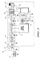
- FIG. 2 illustrates in more detail the system of FIG. 1 in accordance with the inventive arrangements
- FIG. 3 illustrates a method for charging a battery in accordance with the inventive arrangements
- FIG. 4 illustrates a graph of a signal on an input/output line in accordance with the inventive arrangements
- FIG. 5 illustrates a graph of another signal on an input/output line in accordance with the inventive arrangements.
- a or an, as used herein, are defined as one or more than one.
- the term plurality, as used herein, is defined as two or more than two.
- the term another, as used herein, is defined as at least a second or more.
- the terms including and/or having, as used herein, are defined as comprising (i.e., open language).
- the term coupled, as used herein, is defined as connected, although not necessarily directly, and not necessarily mechanically.
- program, software application, and the like as used herein, are defined as a sequence of instructions designed for execution on a computer system.
- a program, computer program, or software application may include a subroutine, a function, a procedure, an object method, an object implementation, an executable application, an applet, a servlet, a source code, an object code, a shared library/dynamic load library and/or other sequence of instructions designed for execution on a computer system.
- the battery 110 can include a battery charging circuit 112 and a charging monitor 114 .
- the system 100 can include a charger 116 , a power supply 117 and an electronic device 118 .
- the battery 110 can provide power to the electronic device 118 , and the electronic device 118 can be a cellular telephone, a two-way radio, a personal digital assistant or a messaging device or any other suitable unit that can receive power from the battery 110 .
- the electronic device 118 can include an electronic device charging circuit 120 , a display 122 and a processor 124 , which can be coupled to the electronic device charging circuit 120 and the display 122 . Additionally, the electronic device charging circuit 120 can direct a charging current to the battery 110 if a charging current is being fed to the electronic device 118 .
- the display 122 can include a charging indicator 126 , which can be used to indicate to a user the level of charge of the battery 110 .
- the charger 116 can supply a charging current to the battery charging circuit 112 , which can be used to charge one or more cells 128 of the battery 110 .
- the charging monitor 114 can sense and monitor the charging current and the charging voltage on the battery 110 and can manipulate the battery charging circuit 112 to control both of them.
- the charging monitor 114 can selectively signal the processor 124 of the electronic device 118 to indicate to the electronic device 118 at least one parameter of the battery 110 as the battery 110 is receiving the charging current.
- the charging monitor 114 can signal the processor 124 of the electronic device 118 to indicate the status of a charging state of the battery 110 ., i.e., whether the battery 110 is receiving a charging current from the charger 116 .
- the charging monitor 114 can also signal the processor 124 to indicate when the charging current has reached a predetermined threshold.
- the processor 124 can be programmed to perform several functions. As an example, if the charging monitor 114 signals the processor 124 that the battery 110 is currently receiving a charging current from the charger 116 , the processor 124 can disable the electronic device charging circuit 120 . This process can prevent the battery from receiving excessive charging current. As another example, if the charging monitor 114 signals the processor 124 that the charging current supplied to the battery charging circuit 112 has reached a predetermined threshold, the processor 124 can update the charging indicator 126 of the display 122 . Through this input, a user can obtain a more accurate reading of the charge level of the battery 110 .
- the charger 116 can include a first coil 129
- the battery charging circuit 112 can include a second coil 130 .
- the battery charging circuit 112 can also include a rectifier 132 , a smoothing capacitor 134 , a current sensor 136 and a current control device 138 , which can be coupled to the cells 128 .
- the current sensor 136 and the current control device 138 can be coupled to the charging monitor 114 , and the charging monitor 114 can control the operation of the current control device 138 .
- the charger 116 can be a wireless charger.
- the first coil 129 can generate a charging current in the second coil 130 of the battery charging circuit 112 .
- the charger 116 can also be a conventional charger in which charging current is supplied through a charging wire.
- the charging monitor 114 can be a processor.
- the charging monitor 114 can include one or more analog-to-digital converters (not shown) for digitally converting analog signals.
- the inputs from the current sensor 136 can be coupled to A/D converters of the charging monitor 114 .
- the battery 110 can also have one or more input/output lines 140 , which can be coupled between the charging monitor 114 and the processor 124 of the electronic device 118 .
- these input/output lines 140 can be preexisting reading conductors.
- a preexisting reading conductor can be any conductor that is incorporated into the battery 110 and is initially designed to facilitate charging or operation of the battery 110 by permitting a processor to read any suitable measurement.
- the battery 110 can include a thermistor R T .
- the thermistor R T , a pull-up resistor R 2 and a voltage supply V S can form a voltage divider.
- the resistance of a thermistor can correspondingly vary, which, in this case, can modify the voltage that the processor 124 or the charging monitor 114 can read on the relevant input/out line 140 , i.e., the preexisting reading conductor. This change in voltage allows the processor 124 or the charging monitor 114 to determine the temperature of the battery 110 .
- the battery 110 can include an erasable programmable read-only memory (EPROM) 142 , which can be coupled to another resistor R 1 and the voltage supply V S .
- EPROM erasable programmable read-only memory
- the processor 124 or the charging monitor 114
- the EPROM 142 can prompt the EPROM 142 to enable the processor 124 (or the charging monitor 114 ) to read, for example, charging information about the battery 110 stored in the EPROM 142 .
- the input/output line 140 that serves as the preexisting reading conductor for the thermistor R T can include one or more branches 144 , which can be coupled to A/D converters in the charging monitor 114 and the processor 124 of the electronic device 118 . These branches 144 can facilitate the voltage readings associated with the thermistor R T .
- FIG. 3 shows a method 300 for charging a battery.
- the method 300 of FIG. 3 and the system 100 of FIGS. 1 and 2 are used to describe one another, it is understood that the inventive arrangements can be practiced in any other suitable system.
- the method 300 can begin.
- a charging current can be supplied to a battery.
- the charger 116 can be a wireless charger, and a charging current can be induced in the second coil 130 of the battery charging circuit 112 .
- the rectifier 132 can rectify the charging current, and the smoothing capacitor 134 can reduce the fluctuation of the charging current.
- the charging current to the battery can be sensed.
- the charging monitor 114 can sense the charging current through the current sensor 136 . By sensing the charging current through the current sensor 136 , the charging monitor 114 can initially detect that the battery 110 is receiving a charging current from the charger 116 and can determine its magnitude. The charging monitor 114 can also control the amount of charging current flowing to the cells 128 of the battery 110 by manipulating the current control device 138 . For example, as is known in the art, when the voltage on the battery 110 reaches the maximum charge voltage of the battery 110 , the charging monitor 114 can reduce the magnitude of the charging current by operating the current control device 138 .
- the current control device 138 can be a field effect transistor (FET), although other suitable components are within contemplation.
- the battery can selectively signal the electronic device to indicate at least one parameter of the battery as the battery is receiving the charging current, as shown at step 316 .
- a charging circuit in the electronic device can be disabled, and at step 320 , a charging indicator of the electronic device can be updated. Examples will be illustrated below in reference to FIG. 2 in which the parameters of the battery are a charging state of the battery (whether the battery is being charged) and a predetermined current threshold of the charging current.
- the selectively signaling step 316 can include toggling an input/output line between high and low states, as will also be described below.
- the charging monitor 114 can pull to a high state one of the input/output lines 140 .
- the charging monitor 114 can pull to a high state the input/output line 140 that also serves as the thermistor R T conductor.
- This high state can have a value that is in the high end of the voltage range for the thermistor R T voltage divider, although other suitable values can be used.
- an interrupt can occur at the processor 124 of the electronic device 118 , and the processor 124 can disable the electronic device charging circuit 120 . This step can prevent the battery 110 from receiving excessive charging current should a user accidentally place the battery 110 on the charger 116 while the electronic device 118 is coupled to another charger.
- the charging monitor 114 can begin to reduce the magnitude of the charging current through the current control device 138 when it detects that the battery 110 has reached its maximum charge voltage. The charging monitor 114 can continually reduce the value of the charging current until the battery 110 is fully charged.
- the processor 124 of the electronic device 118 may monitor the voltage of the battery 110 as it is being charged, it may not be able to track the charging current. As a result, the processor 124 may not be able to determine when the battery 110 is fully charged when the battery 110 receives a charging current from the charger 116 .
- the charging monitor 114 can pull to a low state the appropriate input/output line 140 .
- the predetermined current threshold can be a current magnitude that indicates that the battery 110 is fully or at least substantially charged to capacity.
- the charging monitor 114 can pull to a low state the input/output line 140 associated with the thermistor R T .
- This step can also cause an interrupt to occur at the processor 124 of the electronic device 118 .
- the value for the low state can be in the low end of the voltage range for the thermistor R T voltage divider, although other suitable values can be employed.
- the processor 124 can update the charging indicator 126 of the display 122 . This update can indicate to a user that the battery 110 is fully charged.
- any suitable input/output line including the input/output line 140 associated with the EPROM 142 can be used to signal the processor 124 of the electronic device 118 .
- the input/output lines 140 can be incorporated into any other suitable preexisting conductor.
- the charging monitor 114 is not limited to being a processor, as presented above. Those of ordinary skill in the art will appreciate that the charging monitor 114 can be comprised of any suitable combination of comparators and switches to carry out the inventive functions.
- the battery 110 can be charged without being attached to the electronic device 118 . In this arrangement, the appropriate pull-up resistors for the thermistor R T and EPROM 142 lines can be incorporated in the battery 110 .
- an input/output line can be toggled between high and low states.
- the selectively signaling step can include the step of toggling the input/output line between a high state, a low state and a release state. Referring to FIGS. 4 and 5 , graphs representing examples of this toggling process are illustrated. Specifically, these voltage versus time graphs demonstrate the signal on an input/output line being pulled between high, low and release states. The voltage represents the voltage on an input/output line, and the numbers on the time axis represent predefined times.
- this operation can be repeated any suitable number of times. Repeating this process can enable the charging monitor 114 to monitor the temperature of the battery 110 as the battery is being charged. Moreover, the processor 124 of the electronic device 118 can distinguish between the proper charging of the battery 110 and an inadvertent shorting of the thermistor R T line to a B+ input (see FIG. 2 ).
- the charging current can already have reached the predetermined current threshold.
- the input/output line 140 e.g., the input/output line 140 associated with the thermistor R T
- this operation can be repeated and allows the charging monitor 114 to determine the temperature of the battery 110 . Also, the processor 124 of the electronic device 118 can distinguish between proper charging of the battery 110 and an inadvertent shorting between the thermistor R T line and ground.
Landscapes
- Engineering & Computer Science (AREA)
- Manufacturing & Machinery (AREA)
- Chemical & Material Sciences (AREA)
- Chemical Kinetics & Catalysis (AREA)
- Electrochemistry (AREA)
- General Chemical & Material Sciences (AREA)
- Power Engineering (AREA)
- Microelectronics & Electronic Packaging (AREA)
- Charge And Discharge Circuits For Batteries Or The Like (AREA)
- Secondary Cells (AREA)
Abstract
Description
Claims (18)
Priority Applications (7)
| Application Number | Priority Date | Filing Date | Title |
|---|---|---|---|
| US10/750,593 US7705565B2 (en) | 2003-12-31 | 2003-12-31 | Method and system for wireless charging |
| PCT/US2004/043798 WO2005065338A2 (en) | 2003-12-31 | 2004-12-28 | Method and system for wireless charging |
| ES04815799T ES2396970T3 (en) | 2003-12-31 | 2004-12-28 | Method and system for wireless charging |
| JP2006547526A JP4435788B2 (en) | 2003-12-31 | 2004-12-28 | Method and system for wireless charging |
| KR1020067013193A KR100894428B1 (en) | 2003-12-31 | 2004-12-28 | Method and system for wireless charging |
| CNB200480039580XA CN100459278C (en) | 2003-12-31 | 2004-12-28 | Method and system for wireless charging |
| EP04815799A EP1702384B1 (en) | 2003-12-31 | 2004-12-28 | Method and system for wireless charging |
Applications Claiming Priority (1)
| Application Number | Priority Date | Filing Date | Title |
|---|---|---|---|
| US10/750,593 US7705565B2 (en) | 2003-12-31 | 2003-12-31 | Method and system for wireless charging |
Publications (2)
| Publication Number | Publication Date |
|---|---|
| US20050156569A1 US20050156569A1 (en) | 2005-07-21 |
| US7705565B2 true US7705565B2 (en) | 2010-04-27 |
Family
ID=34749338
Family Applications (1)
| Application Number | Title | Priority Date | Filing Date |
|---|---|---|---|
| US10/750,593 Expired - Lifetime US7705565B2 (en) | 2003-12-31 | 2003-12-31 | Method and system for wireless charging |
Country Status (7)
| Country | Link |
|---|---|
| US (1) | US7705565B2 (en) |
| EP (1) | EP1702384B1 (en) |
| JP (1) | JP4435788B2 (en) |
| KR (1) | KR100894428B1 (en) |
| CN (1) | CN100459278C (en) |
| ES (1) | ES2396970T3 (en) |
| WO (1) | WO2005065338A2 (en) |
Cited By (41)
| Publication number | Priority date | Publication date | Assignee | Title |
|---|---|---|---|---|
| US20080058029A1 (en) * | 2006-08-31 | 2008-03-06 | Semiconductor Energy Laboratory Co., Ltd. | Wireless communication device |
| US20110225073A1 (en) * | 2010-03-12 | 2011-09-15 | Samsung Electronics Co., Ltd. | Apparatus and method for performing wireless charging |
| US20120086388A1 (en) * | 2010-10-08 | 2012-04-12 | Hon Hai Precision Industry Co., Ltd. | Charging status display circuit and electronic device using the same |
| US20120214462A1 (en) * | 2011-02-18 | 2012-08-23 | Chu Inchang | Wireless charging method and apparatus |
| US20140145515A1 (en) * | 2011-06-10 | 2014-05-29 | Lg Electronics Inc. | Apparatus for handling change in orientation of terminal during wireless power transfer and method thereof |
| US9124109B2 (en) | 2012-03-30 | 2015-09-01 | Toyota Motor Engineering & Manufacturing North America, Inc. | Console assembly with charging state indicator |
| US9450444B2 (en) | 2008-03-07 | 2016-09-20 | Canon Kabushiki Kaisha | Charging apparatus |
| US9711994B2 (en) | 2014-01-31 | 2017-07-18 | Semiconductor Energy Laboratory Co., Ltd. | Electronic device and its operation system |
| US9710033B2 (en) | 2014-02-28 | 2017-07-18 | Semiconductor Energy Laboratory Co., Ltd. | Electronic device |
| US10892088B1 (en) | 2020-02-13 | 2021-01-12 | Texas Institute Of Science, Inc. | Stationary device for contactless electrical energy transmission |
| US10978920B2 (en) | 2014-11-05 | 2021-04-13 | Hewlett-Packard Development Company, L.P. | Assisting wireless transfer of power to a machine |
| US11223222B2 (en) | 2019-09-13 | 2022-01-11 | Texas Institute Of Science, Inc. | Contactless charging apparatus and method for contactless charging |
| US11513763B2 (en) | 2016-02-22 | 2022-11-29 | Sonos, Inc. | Audio response playback |
| US11514898B2 (en) | 2016-02-22 | 2022-11-29 | Sonos, Inc. | Voice control of a media playback system |
| US11646023B2 (en) | 2019-02-08 | 2023-05-09 | Sonos, Inc. | Devices, systems, and methods for distributed voice processing |
| US11646045B2 (en) | 2017-09-27 | 2023-05-09 | Sonos, Inc. | Robust short-time fourier transform acoustic echo cancellation during audio playback |
| US11714600B2 (en) | 2019-07-31 | 2023-08-01 | Sonos, Inc. | Noise classification for event detection |
| US11727933B2 (en) | 2016-10-19 | 2023-08-15 | Sonos, Inc. | Arbitration-based voice recognition |
| US11750969B2 (en) | 2016-02-22 | 2023-09-05 | Sonos, Inc. | Default playback device designation |
| US11778259B2 (en) | 2018-09-14 | 2023-10-03 | Sonos, Inc. | Networked devices, systems and methods for associating playback devices based on sound codes |
| US11790937B2 (en) | 2018-09-21 | 2023-10-17 | Sonos, Inc. | Voice detection optimization using sound metadata |
| US11792590B2 (en) | 2018-05-25 | 2023-10-17 | Sonos, Inc. | Determining and adapting to changes in microphone performance of playback devices |
| US11790911B2 (en) | 2018-09-28 | 2023-10-17 | Sonos, Inc. | Systems and methods for selective wake word detection using neural network models |
| US11797263B2 (en) | 2018-05-10 | 2023-10-24 | Sonos, Inc. | Systems and methods for voice-assisted media content selection |
| US11798553B2 (en) | 2019-05-03 | 2023-10-24 | Sonos, Inc. | Voice assistant persistence across multiple network microphone devices |
| US11817083B2 (en) | 2018-12-13 | 2023-11-14 | Sonos, Inc. | Networked microphone devices, systems, and methods of localized arbitration |
| US11816393B2 (en) | 2017-09-08 | 2023-11-14 | Sonos, Inc. | Dynamic computation of system response volume |
| US11817076B2 (en) | 2017-09-28 | 2023-11-14 | Sonos, Inc. | Multi-channel acoustic echo cancellation |
| US11854547B2 (en) | 2019-06-12 | 2023-12-26 | Sonos, Inc. | Network microphone device with command keyword eventing |
| US11863593B2 (en) | 2016-02-22 | 2024-01-02 | Sonos, Inc. | Networked microphone device control |
| US11862161B2 (en) | 2019-10-22 | 2024-01-02 | Sonos, Inc. | VAS toggle based on device orientation |
| US11869503B2 (en) | 2019-12-20 | 2024-01-09 | Sonos, Inc. | Offline voice control |
| US11881222B2 (en) | 2020-05-20 | 2024-01-23 | Sonos, Inc | Command keywords with input detection windowing |
| US11881223B2 (en) | 2018-12-07 | 2024-01-23 | Sonos, Inc. | Systems and methods of operating media playback systems having multiple voice assistant services |
| US11887598B2 (en) | 2020-01-07 | 2024-01-30 | Sonos, Inc. | Voice verification for media playback |
| US11893308B2 (en) | 2017-09-29 | 2024-02-06 | Sonos, Inc. | Media playback system with concurrent voice assistance |
| US11899519B2 (en) | 2018-10-23 | 2024-02-13 | Sonos, Inc. | Multiple stage network microphone device with reduced power consumption and processing load |
| US11900937B2 (en) | 2017-08-07 | 2024-02-13 | Sonos, Inc. | Wake-word detection suppression |
| US11934742B2 (en) | 2016-08-05 | 2024-03-19 | Sonos, Inc. | Playback device supporting concurrent voice assistants |
| US11961519B2 (en) | 2020-02-07 | 2024-04-16 | Sonos, Inc. | Localized wakeword verification |
| US11973893B2 (en) | 2023-01-23 | 2024-04-30 | Sonos, Inc. | Do not disturb feature for audio notifications |
Families Citing this family (13)
| Publication number | Priority date | Publication date | Assignee | Title |
|---|---|---|---|---|
| JP4289408B2 (en) | 2007-02-27 | 2009-07-01 | ブラザー工業株式会社 | Cordless telephone equipment |
| US20100249552A1 (en) * | 2009-03-31 | 2010-09-30 | Nellcor Puritan Bennett Llc | System And Method For Wirelessly Powering Medical Devices |
| US20110074342A1 (en) * | 2009-09-30 | 2011-03-31 | Nellcor Puritan Bennett Llc | Wireless electricity for electronic devices |
| KR101760632B1 (en) * | 2010-05-19 | 2017-07-21 | 퀄컴 인코포레이티드 | Adaptive wireless energy transfer system |
| US20120194124A1 (en) * | 2011-01-31 | 2012-08-02 | Nokia Corporation | Wireless Battery Charging System |
| CN102694408B (en) * | 2011-09-27 | 2014-06-25 | 华为技术有限公司 | Wireless charging strength indicating method and charged device |
| JP6060515B2 (en) * | 2011-12-22 | 2017-01-18 | ソニー株式会社 | Electronic equipment and power supply system |
| KR101882800B1 (en) | 2012-02-28 | 2018-08-01 | 삼성전자주식회사 | Wireless power receiver and method for controlling thereof |
| KR101920236B1 (en) | 2012-06-19 | 2018-11-20 | 삼성전자주식회사 | Method for charging battery and an electronic device thereof |
| JP2014176170A (en) * | 2013-03-07 | 2014-09-22 | Toshiba Corp | Power incoming apparatus and charging system |
| JP5928908B2 (en) * | 2013-09-30 | 2016-06-01 | カシオ計算機株式会社 | Electronic device, power supply control method, and program |
| JP6642393B2 (en) * | 2016-11-28 | 2020-02-05 | 株式会社オートネットワーク技術研究所 | In-car update system |
| DE102017202167A1 (en) * | 2017-02-10 | 2018-08-16 | Robert Bosch Gmbh | battery device |
Citations (16)
| Publication number | Priority date | Publication date | Assignee | Title |
|---|---|---|---|---|
| US4731813A (en) | 1983-12-30 | 1988-03-15 | Motorola, Inc. | Address encoding system for portable battery-operated devices |
| US5471128A (en) | 1993-11-26 | 1995-11-28 | Motorola, Inc. | Battery and method for charging/discharging the battery |
| US5600225A (en) * | 1994-06-30 | 1997-02-04 | Nippon Electric Co | Noncontacting charging device |
| US5631538A (en) | 1996-04-04 | 1997-05-20 | Motorola, Inc. | Method and apparatus for charging a detachable battery |
| US5734254A (en) | 1996-12-06 | 1998-03-31 | Hewlett-Packard Company | Battery pack and charging system for a portable electronic device |
| JPH11215727A (en) | 1998-01-27 | 1999-08-06 | Sony Corp | Electronic unit with battery charging function and the battery charging method |
| US5963012A (en) | 1998-07-13 | 1999-10-05 | Motorola, Inc. | Wireless battery charging system having adaptive parameter sensing |
| US6025695A (en) | 1997-07-09 | 2000-02-15 | Friel; Daniel D. | Battery operating system |
| US6040680A (en) * | 1997-07-22 | 2000-03-21 | Sanyo Electric Co., Ltd. | Rechargeable battery pack and charging stand for charging the rechargeable battery pack by electromagnetic induction |
| US6057668A (en) * | 1998-09-17 | 2000-05-02 | Shi-Ming Chen | Battery charging device for mobile phone |
| US6184651B1 (en) | 2000-03-20 | 2001-02-06 | Motorola, Inc. | Contactless battery charger with wireless control link |
| GB2352887A (en) | 1999-06-17 | 2001-02-07 | Vtech Communications Ltd | Cordless phone with battery backup |
| KR20010074405A (en) | 2000-01-25 | 2001-08-04 | 윤종용 | A smart battery device having an embedded charging circuit and a control method therefor |
| US6320354B1 (en) * | 2000-07-21 | 2001-11-20 | Motorola, Inc. | Method and apparatus for battery charging |
| US20020175658A1 (en) * | 2001-05-25 | 2002-11-28 | Watts Fred S. | Method and apparatus for charging batteries |
| US6819083B1 (en) | 2003-04-25 | 2004-11-16 | Motorola, Inc. | Dual use thermistor for battery cell thermal protection and battery pack overcharge/undercharge protection |
-
2003
- 2003-12-31 US US10/750,593 patent/US7705565B2/en not_active Expired - Lifetime
-
2004
- 2004-12-28 ES ES04815799T patent/ES2396970T3/en active Active
- 2004-12-28 CN CNB200480039580XA patent/CN100459278C/en active Active
- 2004-12-28 KR KR1020067013193A patent/KR100894428B1/en active IP Right Grant
- 2004-12-28 EP EP04815799A patent/EP1702384B1/en active Active
- 2004-12-28 WO PCT/US2004/043798 patent/WO2005065338A2/en not_active Application Discontinuation
- 2004-12-28 JP JP2006547526A patent/JP4435788B2/en active Active
Patent Citations (16)
| Publication number | Priority date | Publication date | Assignee | Title |
|---|---|---|---|---|
| US4731813A (en) | 1983-12-30 | 1988-03-15 | Motorola, Inc. | Address encoding system for portable battery-operated devices |
| US5471128A (en) | 1993-11-26 | 1995-11-28 | Motorola, Inc. | Battery and method for charging/discharging the battery |
| US5600225A (en) * | 1994-06-30 | 1997-02-04 | Nippon Electric Co | Noncontacting charging device |
| US5631538A (en) | 1996-04-04 | 1997-05-20 | Motorola, Inc. | Method and apparatus for charging a detachable battery |
| US5734254A (en) | 1996-12-06 | 1998-03-31 | Hewlett-Packard Company | Battery pack and charging system for a portable electronic device |
| US6025695A (en) | 1997-07-09 | 2000-02-15 | Friel; Daniel D. | Battery operating system |
| US6040680A (en) * | 1997-07-22 | 2000-03-21 | Sanyo Electric Co., Ltd. | Rechargeable battery pack and charging stand for charging the rechargeable battery pack by electromagnetic induction |
| JPH11215727A (en) | 1998-01-27 | 1999-08-06 | Sony Corp | Electronic unit with battery charging function and the battery charging method |
| US5963012A (en) | 1998-07-13 | 1999-10-05 | Motorola, Inc. | Wireless battery charging system having adaptive parameter sensing |
| US6057668A (en) * | 1998-09-17 | 2000-05-02 | Shi-Ming Chen | Battery charging device for mobile phone |
| GB2352887A (en) | 1999-06-17 | 2001-02-07 | Vtech Communications Ltd | Cordless phone with battery backup |
| KR20010074405A (en) | 2000-01-25 | 2001-08-04 | 윤종용 | A smart battery device having an embedded charging circuit and a control method therefor |
| US6184651B1 (en) | 2000-03-20 | 2001-02-06 | Motorola, Inc. | Contactless battery charger with wireless control link |
| US6320354B1 (en) * | 2000-07-21 | 2001-11-20 | Motorola, Inc. | Method and apparatus for battery charging |
| US20020175658A1 (en) * | 2001-05-25 | 2002-11-28 | Watts Fred S. | Method and apparatus for charging batteries |
| US6819083B1 (en) | 2003-04-25 | 2004-11-16 | Motorola, Inc. | Dual use thermistor for battery cell thermal protection and battery pack overcharge/undercharge protection |
Non-Patent Citations (5)
| Title |
|---|
| European Patent Office, Supplementary European Search Report for Application No. EP 04 81 5799 Applicant Motorola, Inc., Jun. 18, 2009, 3 pages. |
| Japan Patent Office, Decision of Rejection for Application No. 2006-547526 "Method and System for Wireless Charging" Applicant Motorola, Inc., Jun. 9, 2009, 2 pages. |
| Japan Patent Office, Office Action for Application No. 2006-547526, Nov. 18, 2008, 5 pages. |
| Patent Office of the People's Republic of China, Notification of the First Office Action for Application No. 200480039580.X "Method and System for Wireless Charging" Applicant Motorola, Inc., Feb. 15, 2008, 10 pages. |
| World Intellectual Property Organization, International Search Report for Application No. PCT/US2004/043798, Sep. 1, 2005, 1 page. |
Cited By (54)
| Publication number | Priority date | Publication date | Assignee | Title |
|---|---|---|---|---|
| US8463332B2 (en) * | 2006-08-31 | 2013-06-11 | Semiconductor Energy Laboratory Co., Ltd. | Wireless communication device |
| US20080058029A1 (en) * | 2006-08-31 | 2008-03-06 | Semiconductor Energy Laboratory Co., Ltd. | Wireless communication device |
| US9450444B2 (en) | 2008-03-07 | 2016-09-20 | Canon Kabushiki Kaisha | Charging apparatus |
| US20110225073A1 (en) * | 2010-03-12 | 2011-09-15 | Samsung Electronics Co., Ltd. | Apparatus and method for performing wireless charging |
| US9190849B2 (en) * | 2010-03-12 | 2015-11-17 | Samsung Electronics Co., Ltd | Apparatus and method for performing wireless charging |
| US20120086388A1 (en) * | 2010-10-08 | 2012-04-12 | Hon Hai Precision Industry Co., Ltd. | Charging status display circuit and electronic device using the same |
| US8633676B2 (en) * | 2010-10-08 | 2014-01-21 | Hong Fu Jin Precision Industry (Shenzhen) Co., Ltd | Charging status display circuit and electronic device using the same |
| US20120214462A1 (en) * | 2011-02-18 | 2012-08-23 | Chu Inchang | Wireless charging method and apparatus |
| US8903456B2 (en) * | 2011-02-18 | 2014-12-02 | Lg Electronics Inc. | Wireless charging method and apparatus |
| US10574300B2 (en) | 2011-06-10 | 2020-02-25 | Lg Electronics Inc. | Apparatus for handling change in orientation of terminal during wireless power transfer and method thereof |
| US20140145515A1 (en) * | 2011-06-10 | 2014-05-29 | Lg Electronics Inc. | Apparatus for handling change in orientation of terminal during wireless power transfer and method thereof |
| US9692487B2 (en) * | 2011-06-10 | 2017-06-27 | Lg Electronics Inc. | Apparatus for handling change in orientation of terminal during wireless power transfer and method thereof |
| US9124109B2 (en) | 2012-03-30 | 2015-09-01 | Toyota Motor Engineering & Manufacturing North America, Inc. | Console assembly with charging state indicator |
| US9711994B2 (en) | 2014-01-31 | 2017-07-18 | Semiconductor Energy Laboratory Co., Ltd. | Electronic device and its operation system |
| US11043851B2 (en) | 2014-01-31 | 2021-06-22 | Semiconductor Energy Laboratory Co., Ltd. | Electronic device and its operation system |
| US10530189B2 (en) | 2014-01-31 | 2020-01-07 | Semiconductor Energy Laboratory Co., Ltd. | Electronic device and its operation system |
| US11899886B2 (en) | 2014-02-28 | 2024-02-13 | Semiconductor Energy Laboratory Co., Ltd. | Electronic device |
| US11474646B2 (en) | 2014-02-28 | 2022-10-18 | Semiconductor Energy Laboratory Co., Ltd. | Electronic device |
| US9710033B2 (en) | 2014-02-28 | 2017-07-18 | Semiconductor Energy Laboratory Co., Ltd. | Electronic device |
| US10139879B2 (en) | 2014-02-28 | 2018-11-27 | Semiconductor Energy Laboratory Co., Ltd. | Electronic device |
| US10809784B2 (en) | 2014-02-28 | 2020-10-20 | Semiconductor Energy Laboratory Co., Ltd. | Electronic device |
| US10978920B2 (en) | 2014-11-05 | 2021-04-13 | Hewlett-Packard Development Company, L.P. | Assisting wireless transfer of power to a machine |
| US11513763B2 (en) | 2016-02-22 | 2022-11-29 | Sonos, Inc. | Audio response playback |
| US11514898B2 (en) | 2016-02-22 | 2022-11-29 | Sonos, Inc. | Voice control of a media playback system |
| US11863593B2 (en) | 2016-02-22 | 2024-01-02 | Sonos, Inc. | Networked microphone device control |
| US11750969B2 (en) | 2016-02-22 | 2023-09-05 | Sonos, Inc. | Default playback device designation |
| US11832068B2 (en) | 2016-02-22 | 2023-11-28 | Sonos, Inc. | Music service selection |
| US11934742B2 (en) | 2016-08-05 | 2024-03-19 | Sonos, Inc. | Playback device supporting concurrent voice assistants |
| US11727933B2 (en) | 2016-10-19 | 2023-08-15 | Sonos, Inc. | Arbitration-based voice recognition |
| US11900937B2 (en) | 2017-08-07 | 2024-02-13 | Sonos, Inc. | Wake-word detection suppression |
| US11816393B2 (en) | 2017-09-08 | 2023-11-14 | Sonos, Inc. | Dynamic computation of system response volume |
| US11646045B2 (en) | 2017-09-27 | 2023-05-09 | Sonos, Inc. | Robust short-time fourier transform acoustic echo cancellation during audio playback |
| US11817076B2 (en) | 2017-09-28 | 2023-11-14 | Sonos, Inc. | Multi-channel acoustic echo cancellation |
| US11893308B2 (en) | 2017-09-29 | 2024-02-06 | Sonos, Inc. | Media playback system with concurrent voice assistance |
| US11797263B2 (en) | 2018-05-10 | 2023-10-24 | Sonos, Inc. | Systems and methods for voice-assisted media content selection |
| US11792590B2 (en) | 2018-05-25 | 2023-10-17 | Sonos, Inc. | Determining and adapting to changes in microphone performance of playback devices |
| US11778259B2 (en) | 2018-09-14 | 2023-10-03 | Sonos, Inc. | Networked devices, systems and methods for associating playback devices based on sound codes |
| US11790937B2 (en) | 2018-09-21 | 2023-10-17 | Sonos, Inc. | Voice detection optimization using sound metadata |
| US11790911B2 (en) | 2018-09-28 | 2023-10-17 | Sonos, Inc. | Systems and methods for selective wake word detection using neural network models |
| US11899519B2 (en) | 2018-10-23 | 2024-02-13 | Sonos, Inc. | Multiple stage network microphone device with reduced power consumption and processing load |
| US11881223B2 (en) | 2018-12-07 | 2024-01-23 | Sonos, Inc. | Systems and methods of operating media playback systems having multiple voice assistant services |
| US11817083B2 (en) | 2018-12-13 | 2023-11-14 | Sonos, Inc. | Networked microphone devices, systems, and methods of localized arbitration |
| US11646023B2 (en) | 2019-02-08 | 2023-05-09 | Sonos, Inc. | Devices, systems, and methods for distributed voice processing |
| US11798553B2 (en) | 2019-05-03 | 2023-10-24 | Sonos, Inc. | Voice assistant persistence across multiple network microphone devices |
| US11854547B2 (en) | 2019-06-12 | 2023-12-26 | Sonos, Inc. | Network microphone device with command keyword eventing |
| US11714600B2 (en) | 2019-07-31 | 2023-08-01 | Sonos, Inc. | Noise classification for event detection |
| US11223222B2 (en) | 2019-09-13 | 2022-01-11 | Texas Institute Of Science, Inc. | Contactless charging apparatus and method for contactless charging |
| US11862161B2 (en) | 2019-10-22 | 2024-01-02 | Sonos, Inc. | VAS toggle based on device orientation |
| US11869503B2 (en) | 2019-12-20 | 2024-01-09 | Sonos, Inc. | Offline voice control |
| US11887598B2 (en) | 2020-01-07 | 2024-01-30 | Sonos, Inc. | Voice verification for media playback |
| US11961519B2 (en) | 2020-02-07 | 2024-04-16 | Sonos, Inc. | Localized wakeword verification |
| US10892088B1 (en) | 2020-02-13 | 2021-01-12 | Texas Institute Of Science, Inc. | Stationary device for contactless electrical energy transmission |
| US11881222B2 (en) | 2020-05-20 | 2024-01-23 | Sonos, Inc | Command keywords with input detection windowing |
| US11973893B2 (en) | 2023-01-23 | 2024-04-30 | Sonos, Inc. | Do not disturb feature for audio notifications |
Also Published As
| Publication number | Publication date |
|---|---|
| KR20060107569A (en) | 2006-10-13 |
| KR100894428B1 (en) | 2009-04-22 |
| JP2007520182A (en) | 2007-07-19 |
| EP1702384A4 (en) | 2009-07-22 |
| CN100459278C (en) | 2009-02-04 |
| WO2005065338A3 (en) | 2005-10-20 |
| EP1702384B1 (en) | 2012-10-03 |
| US20050156569A1 (en) | 2005-07-21 |
| WO2005065338A2 (en) | 2005-07-21 |
| ES2396970T3 (en) | 2013-03-01 |
| JP4435788B2 (en) | 2010-03-24 |
| EP1702384A2 (en) | 2006-09-20 |
| CN1902779A (en) | 2007-01-24 |
Similar Documents
| Publication | Publication Date | Title |
|---|---|---|
| US7705565B2 (en) | Method and system for wireless charging | |
| RU2141155C1 (en) | Method and device for determining type of external power supply | |
| US7622895B1 (en) | Power level display calibration device | |
| EP1964235B1 (en) | Battery full-charge detection for charge-and-play circuits | |
| US20060022677A1 (en) | Method and system for battery state of charge estimation | |
| US6163132A (en) | Battery charging status indicator apparatus | |
| JP5198489B2 (en) | Charging circuit, mobile device and charging method | |
| US20070013341A1 (en) | Battery pack | |
| US20040138836A1 (en) | Apparatus and method for calculating offset value for an electric sensor | |
| CN1973416A (en) | Battery charging method and apparatus therefor | |
| JP2009043554A (en) | Battery pack, charging device, and charging system | |
| US20100182155A1 (en) | Device and method for detecting loading of battery | |
| JP2005312239A (en) | Charging method for secondary battery and battery pack | |
| US6420853B1 (en) | Battery charger capable of accurately determining fully charged condition regardless of batteries with different charge chracteristics | |
| EP1315977B1 (en) | Electronic apparatus and control method | |
| US7876068B2 (en) | Battery charge indicator | |
| US20220283241A1 (en) | Battery Management Apparatus | |
| CN109066892B (en) | Split screen electronic equipment charging circuit and charging control method | |
| EP1864148B1 (en) | Method for determining capacity of lead-acid batteries of various specific gravities | |
| JP3474535B2 (en) | Battery state determination device | |
| JP3945134B2 (en) | Limiter control circuit, limiter control circuit adjustment method, external adjustment device, and external adjustment device control method | |
| CN111740465B (en) | Battery charge-discharge detection device and intelligent wearable equipment | |
| KR20010065381A (en) | The device for detecting temperature of litum-ion battery | |
| WO2023034034A1 (en) | Systems and methods for detecting both vehicle battery connection and vehicle battery polarity using a single sensor circuit | |
| JP2000123884A (en) | Electronic equipment |
Legal Events
| Date | Code | Title | Description |
|---|---|---|---|
| AS | Assignment |
Owner name: MOTOROLA, INC., ILLINOIS Free format text: ASSIGNMENT OF ASSIGNORS INTEREST;ASSIGNOR:PATINO, JOSEPH;REEL/FRAME:014864/0669 Effective date: 20031231 Owner name: MOTOROLA, INC.,ILLINOIS Free format text: ASSIGNMENT OF ASSIGNORS INTEREST;ASSIGNOR:PATINO, JOSEPH;REEL/FRAME:014864/0669 Effective date: 20031231 |
|
| AS | Assignment |
Owner name: MOTOROLA, INC., ILLINOIS Free format text: ASSIGNMENT OF ASSIGNORS INTEREST;ASSIGNOR:COAPSTICK, RONALD S.;REEL/FRAME:015471/0469 Effective date: 20040615 Owner name: MOTOROLA, INC.,ILLINOIS Free format text: ASSIGNMENT OF ASSIGNORS INTEREST;ASSIGNOR:COAPSTICK, RONALD S.;REEL/FRAME:015471/0469 Effective date: 20040615 |
|
| STCF | Information on status: patent grant |
Free format text: PATENTED CASE |
|
| AS | Assignment |
Owner name: MOTOROLA MOBILITY, INC, ILLINOIS Free format text: ASSIGNMENT OF ASSIGNORS INTEREST;ASSIGNOR:MOTOROLA, INC;REEL/FRAME:025673/0558 Effective date: 20100731 |
|
| AS | Assignment |
Owner name: MOTOROLA MOBILITY LLC, ILLINOIS Free format text: CHANGE OF NAME;ASSIGNOR:MOTOROLA MOBILITY, INC.;REEL/FRAME:029216/0282 Effective date: 20120622 |
|
| FPAY | Fee payment |
Year of fee payment: 4 |
|
| AS | Assignment |
Owner name: GOOGLE TECHNOLOGY HOLDINGS LLC, CALIFORNIA Free format text: ASSIGNMENT OF ASSIGNORS INTEREST;ASSIGNOR:MOTOROLA MOBILITY LLC;REEL/FRAME:034316/0001 Effective date: 20141028 |
|
| MAFP | Maintenance fee payment |
Free format text: PAYMENT OF MAINTENANCE FEE, 8TH YEAR, LARGE ENTITY (ORIGINAL EVENT CODE: M1552) Year of fee payment: 8 |
|
| MAFP | Maintenance fee payment |
Free format text: PAYMENT OF MAINTENANCE FEE, 12TH YEAR, LARGE ENTITY (ORIGINAL EVENT CODE: M1553); ENTITY STATUS OF PATENT OWNER: LARGE ENTITY Year of fee payment: 12 |
|
| AS | Assignment |
Owner name: GOOGLE LLC, CALIFORNIA Free format text: ASSIGNMENT OF ASSIGNORS INTEREST;ASSIGNOR:GOOGLE TECHNOLOGY HOLDINGS LLC;REEL/FRAME:060730/0042 Effective date: 20220804 |