US7708925B2 - Nitinol frame heating and setting mandrel - Google Patents
Nitinol frame heating and setting mandrel Download PDFInfo
- Publication number
- US7708925B2 US7708925B2 US11/501,987 US50198706A US7708925B2 US 7708925 B2 US7708925 B2 US 7708925B2 US 50198706 A US50198706 A US 50198706A US 7708925 B2 US7708925 B2 US 7708925B2
- Authority
- US
- United States
- Prior art keywords
- stent
- mandrel
- shape
- outer cylinders
- hooks
- Prior art date
- Legal status (The legal status is an assumption and is not a legal conclusion. Google has not performed a legal analysis and makes no representation as to the accuracy of the status listed.)
- Expired - Fee Related, expires
Links
Images


Classifications
-
- A—HUMAN NECESSITIES
- A61—MEDICAL OR VETERINARY SCIENCE; HYGIENE
- A61F—FILTERS IMPLANTABLE INTO BLOOD VESSELS; PROSTHESES; DEVICES PROVIDING PATENCY TO, OR PREVENTING COLLAPSING OF, TUBULAR STRUCTURES OF THE BODY, e.g. STENTS; ORTHOPAEDIC, NURSING OR CONTRACEPTIVE DEVICES; FOMENTATION; TREATMENT OR PROTECTION OF EYES OR EARS; BANDAGES, DRESSINGS OR ABSORBENT PADS; FIRST-AID KITS
- A61F2/00—Filters implantable into blood vessels; Prostheses, i.e. artificial substitutes or replacements for parts of the body; Appliances for connecting them with the body; Devices providing patency to, or preventing collapsing of, tubular structures of the body, e.g. stents
- A61F2/82—Devices providing patency to, or preventing collapsing of, tubular structures of the body, e.g. stents
- A61F2/86—Stents in a form characterised by the wire-like elements; Stents in the form characterised by a net-like or mesh-like structure
- A61F2/90—Stents in a form characterised by the wire-like elements; Stents in the form characterised by a net-like or mesh-like structure characterised by a net-like or mesh-like structure
- A61F2/91—Stents in a form characterised by the wire-like elements; Stents in the form characterised by a net-like or mesh-like structure characterised by a net-like or mesh-like structure made from perforated sheet material or tubes, e.g. perforated by laser cuts or etched holes
-
- A—HUMAN NECESSITIES
- A61—MEDICAL OR VETERINARY SCIENCE; HYGIENE
- A61F—FILTERS IMPLANTABLE INTO BLOOD VESSELS; PROSTHESES; DEVICES PROVIDING PATENCY TO, OR PREVENTING COLLAPSING OF, TUBULAR STRUCTURES OF THE BODY, e.g. STENTS; ORTHOPAEDIC, NURSING OR CONTRACEPTIVE DEVICES; FOMENTATION; TREATMENT OR PROTECTION OF EYES OR EARS; BANDAGES, DRESSINGS OR ABSORBENT PADS; FIRST-AID KITS
- A61F2220/00—Fixations or connections for prostheses classified in groups A61F2/00 - A61F2/26 or A61F2/82 or A61F9/00 or A61F11/00 or subgroups thereof
- A61F2220/0008—Fixation appliances for connecting prostheses to the body
- A61F2220/0016—Fixation appliances for connecting prostheses to the body with sharp anchoring protrusions, e.g. barbs, pins, spikes
-
- A—HUMAN NECESSITIES
- A61—MEDICAL OR VETERINARY SCIENCE; HYGIENE
- A61F—FILTERS IMPLANTABLE INTO BLOOD VESSELS; PROSTHESES; DEVICES PROVIDING PATENCY TO, OR PREVENTING COLLAPSING OF, TUBULAR STRUCTURES OF THE BODY, e.g. STENTS; ORTHOPAEDIC, NURSING OR CONTRACEPTIVE DEVICES; FOMENTATION; TREATMENT OR PROTECTION OF EYES OR EARS; BANDAGES, DRESSINGS OR ABSORBENT PADS; FIRST-AID KITS
- A61F2230/00—Geometry of prostheses classified in groups A61F2/00 - A61F2/26 or A61F2/82 or A61F9/00 or A61F11/00 or subgroups thereof
- A61F2230/0002—Two-dimensional shapes, e.g. cross-sections
- A61F2230/0028—Shapes in the form of latin or greek characters
- A61F2230/005—Rosette-shaped, e.g. star-shaped
-
- A—HUMAN NECESSITIES
- A61—MEDICAL OR VETERINARY SCIENCE; HYGIENE
- A61F—FILTERS IMPLANTABLE INTO BLOOD VESSELS; PROSTHESES; DEVICES PROVIDING PATENCY TO, OR PREVENTING COLLAPSING OF, TUBULAR STRUCTURES OF THE BODY, e.g. STENTS; ORTHOPAEDIC, NURSING OR CONTRACEPTIVE DEVICES; FOMENTATION; TREATMENT OR PROTECTION OF EYES OR EARS; BANDAGES, DRESSINGS OR ABSORBENT PADS; FIRST-AID KITS
- A61F2230/00—Geometry of prostheses classified in groups A61F2/00 - A61F2/26 or A61F2/82 or A61F9/00 or A61F11/00 or subgroups thereof
- A61F2230/0002—Two-dimensional shapes, e.g. cross-sections
- A61F2230/0028—Shapes in the form of latin or greek characters
- A61F2230/0054—V-shaped
-
- A—HUMAN NECESSITIES
- A61—MEDICAL OR VETERINARY SCIENCE; HYGIENE
- A61F—FILTERS IMPLANTABLE INTO BLOOD VESSELS; PROSTHESES; DEVICES PROVIDING PATENCY TO, OR PREVENTING COLLAPSING OF, TUBULAR STRUCTURES OF THE BODY, e.g. STENTS; ORTHOPAEDIC, NURSING OR CONTRACEPTIVE DEVICES; FOMENTATION; TREATMENT OR PROTECTION OF EYES OR EARS; BANDAGES, DRESSINGS OR ABSORBENT PADS; FIRST-AID KITS
- A61F2240/00—Manufacturing or designing of prostheses classified in groups A61F2/00 - A61F2/26 or A61F2/82 or A61F9/00 or A61F11/00 or subgroups thereof
- A61F2240/001—Designing or manufacturing processes
-
- Y—GENERAL TAGGING OF NEW TECHNOLOGICAL DEVELOPMENTS; GENERAL TAGGING OF CROSS-SECTIONAL TECHNOLOGIES SPANNING OVER SEVERAL SECTIONS OF THE IPC; TECHNICAL SUBJECTS COVERED BY FORMER USPC CROSS-REFERENCE ART COLLECTIONS [XRACs] AND DIGESTS
- Y10—TECHNICAL SUBJECTS COVERED BY FORMER USPC
- Y10S—TECHNICAL SUBJECTS COVERED BY FORMER USPC CROSS-REFERENCE ART COLLECTIONS [XRACs] AND DIGESTS
- Y10S425/00—Plastic article or earthenware shaping or treating: apparatus
- Y10S425/014—Expansible and collapsible
Definitions
- This application relates to heating and setting mandrels for use in manufacturing and more particularly, a mandrel for heating and setting a stent having limb elements which provide for improved expansion characteristics.
- stent generally refers to a prosthesis, which can be introduced into a corporeal lumen and expanded to support that lumen or attach a conduit to the inner surface of that lumen.
- Self-expanding stents are generally known in the art. During use, the self-expanding stent is compressed into a reduced size having an outer diameter substantially smaller than the stent in its expanded shape. The stent is held in its compressed state during its passage through the patient's vascular system until reaching the target treatment site, whereupon the compressed self-expanding stent may be deployed. While in its compressed state, stress is stored in the bends of the stent limbs. During deployment, the stresses in the stent limbs cause the stent to expand radially from its initially compressed state. Once in place, the radial extremities of the stent bear against the inside walls of the passageway, thereby allowing normal blood flow.
- the processes of manufacturing self-expanding stents are also known in the art insofar as heat treating a stent upon a mandrel for purposes of setting a particular stent shape. Additionally, shape memorization processes utilizing mandrels are stent specific as each stent-type embody different design requirements. Previous attempts at heat treating simply involve mounting a stent upon a mandrel and exposing it to heat with little attention being paid to the shape that is set, other than the diameter, during the heating process. Because these previous attempts fail to control the shape of the stent limbs created during the heating process, a less effective final stent is produced.
- stents known in the art change diameter through the deformation of a small percentage of a length of the limbs defining the stent. Usually, this deformation occurs only at, or near, curved apices formed in stent limbs.
- the length of the limb that deforms and the magnitude of the deformation has a bearing on three important and interrelated characteristics of the stent: 1) the minimum diameter to which the stent can be compressed; 2) the radial stiffness or energy required to compress the stent; and 3) the maximum value of stress/strain experienced by the stent. Many other factors are also determinative of these characteristics including stent material, resting diameter, stent length, etc.; however, these other factors are assumed to be generally constant for a given stent design.
- a stent having curved limb members can improve the above mentioned characteristics of the stent by spreading the deformation energy over a majority of the length of the stent limbs. This is in contrast to other stent designs that concentrate the deformation at or near the apices in the stent limb.
- limb elements defining the stent each can embody two curves of constant radius and opposite direction which meet at an inflection point.
- the two curved sections assume a nearly straight profile, the advantage of which is that the entire length of the curved portions store deformation energy and function to urge the stent radially outward.
- a stent having curved limb members In the event a stent having curved limb members is to be manufactured, in order to set a desired expanded configuration the stent is expanded over a cylindrical mandrel and heated. However, merely expanding the stent over a mandrel without additional controls or constraints, rarely results in limb elements having the desired profile. To wit, the end of the limbs may be provided with a smaller than desired radius of curvature whereas the portion of the limbs near an inflection point may have a much larger than desired radius of curvature. This results in producing a stent that embodies limbs which do not store stress in an optimal manner.
- stents are currently expanded on a mandrel through multiple shape setting steps, and at some point before the last expansion, an additional ring is placed on the stent to help protrude hooks from the stent. This process is very slow and prone to damaging the stent. Therefore, an alternative process is needed to make the hook-setting step easier, faster, and less susceptible to damage.
- the present invention satisfies these and other needs.
- the present invention provides an improved heating/setting mandrel which substantially reduces the difficulty in loading stents onto the mandrel. Moreover, the mandrel construction of the present invention is relatively inexpensive to manufacture, is trouble-free and reliable in use, and attains improved and constant results in the manufacture of stents having curved limb elements.
- the present invention also provides an improved mandrel and method for setting hooks of a stent.
- the present invention makes the hook-setting step easier, faster, and the stent is less prone to damage.
- the invention comprises a hollow central core cylinder made from a heat conducting material having an outer surface including a plurality of raised forms, gaps in-between the raised forms, and the central core cylinder has an outer surface diameter and a raised form diameter.
- the invention also includes a first and second outer cylinder, also made from a heat conducting material, and each having a curved radial end with a cut-out design similar to the shape of the plurality of raised forms.
- the first and second outer cylinders each have an inner diameter that is nearly equivalent to or slightly larger than the outer surface diameter of the central core cylinder, and the inner diameter is less than the raised form diameter.
- a stent is placed on the central core cylinder with the limb elements of the stent directed around the raised forms in the gaps in-between.
- the first and second outer cylinders are slid onto the central core cylinder at opposite ends such that the curved radial ends of the first and second outer cylinders align with the plurality of raised forms and force the stent into the shape of the raised forms.
- the first and second outer cylinders may also include a plurality of hook extenders disposed at the curved radial ends which shape hooks of a stent.
- the invention further includes a capture sleeve having a cylindrical shape with an inner diameter nearly equivalent to or slightly larger than the raised form diameter of the central core cylinder.
- the capture sleeve fits over the central core cylinder and the plurality of raised forms, leaving an insert space for the first and second outer cylinders to be inserted between the capture sleeve and the central core mandrel.
- the present invention includes a mandrel having an outer surface with a plurality of slots disposed thereon corresponding to the position of hooks on a stent.
- first and second stop rings may be used to engage opposite ends of the mandrel and to press against ends of the stent, holding the stent in place on the mandrel.
- a method of using this mandrel includes turning a stent inside-out, and positioning the stent on the mandrel such that the hooks are aligned with the plurality of slots. Once on the mandrel, the hooks are then pushed into the slots, and the apparatus and stent are heated to set the hooks.
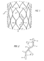
- FIG. 1 is a perspective view with some elements in the background not shown for clarity, depicting a stent having curved limb elements to be manufactured with the present invention
- FIG. 2 is a side view, depicting a single curved limb element of the stent of FIG. 1 ;
- FIG. 3 is a side view, depicting a curved limb element of a stent to be used in the present invention
- FIG. 4 is a side view, depicting typical joints between adjacent curved limb elements in a stent which is comprised of a multiplicity of such curved limb elements;
- FIG. 5 is a side view, depicting an almond shaped stent cell of a stent to be used in the present invention
- FIG. 6 is an exploded perspective view of one embodiment of the present invention.
- FIG. 7 is an elevational view of the first and second outer cylinders having hook extenders
- FIG. 8 is a partial elevational view of hook extenders shaping a hook of a stent
- FIG. 9 is an elevational view of another embodiment of the present invention.
- FIG. 10 is an elevational view of the embodiment shown in FIG. 4 with a stent in position on the mandrel;
- FIG. 11 is a perspective view of a stent with the hooks facing outward;
- FIG. 12 is a perspective view of a stent pushed flat against a surface.
- FIG. 13 is a perspective view of a stent turned inside-out with the hooks facing inward.
- the present invention is directed to an improved mandrel for use in heating and setting a stent having curved limb elements which alleviates the stresses inflicted upon the limbs of the stent during the manufacturing.
- the mandrel shapes the limbs of the stent during the heating process by employing the use of raised forms and outer cylinders which hold in place the limb portions of the stent to thereby produce a stent with limb portions having constant radius of curvatures.
- FIG. 1 there is shown an example of a stent 8 having curved limb elements to be manufactured with the present mandrel invention.
- a stent 8 may be cut from a tube or assembled from separate elements.
- FIG. 2 depicts a repeating element of each limb 10 of a stent cell, having two curved elements 12 of equal radius, equal length and opposite direction.
- the short straight segment element 16 at the ends of each limb 10 are parallel to one another.
- the mid-portion or the inflection point 18 lies between the two curved segment elements 12 of each stent limb 10 .
- the limb element 10 may bend back and forth in a sinusoid wave pattern down the length of the stent 8 .
- the short straight segment elements 16 of adjacent limbs maybe joined, either by welding, soldering, riveting, or gluing to form joint 20 .
- a multiplicity of identical limb elements can be joined in this way to form the cylindrical stent structure, as seen in FIG. 1 .
- a stent cell 22 may have an almond-like shape and each cell may embody four limb elements 10 .
- Each limb 10 essentially comprises a quarter of a full stent cell 22 .
- one limb 10 making up a quarter of the stent cell 22 , starts from the midpoint of the stent cell to the end of the stent cell.
- the limb elements 10 are comprised of two curve elements 12 . These curve elements 12 are of equal radius, equal length and opposite direction.
- the limb 10 would be composed of two curves having constant radius r with an inflection point 18 in the middle where they reverse direction.
- the stress along the length of the limb 10 be as evenly distributed as possible so that there is minimal or no stress at the inflection point 18 .
- the stress level will be determined by the inverse of the radius r that the stent 8 limb has in its relaxed configuration.
- the stent 8 is compressed down into a catheter (not shown). In this compressed configuration, the curved limb elements 12 become generally straight.
- the change in radius r of curvature from the compressed state where the limbs 10 are straight to its profile in a relaxed state has a bearing on the amount of stress.
- the stress along the limb 10 and the amount of energy that can be stored in the stent 8 is determined by the change in the radius of curvature at any point along the limb 10 .
- a mandrel generally designated 30 for heating and setting elements of the stent 8 , includes a central core cylinder 32 having an outer surface 34 with a plurality of raised forms 36 , gaps 38 in-between the raised forms, and the central core cylinder also has an outer surface diameter 40 and a raised form diameter 42 .
- the raised forms 36 may be in any shape which is desired for the stent cell 22 , and in this embodiment the raised forms are almond-shape.
- the mandrel 30 also has a first outer cylinder 44 and a second outer cylinder 46 , each having a curved radial end 48 with a cut-out design 50 similar to one-half the shape of the plurality of raised forms 36 .
- the cut-out designs 50 are one-half almond.
- the first and second outer cylinders 44 and 46 each have an inner diameter 52 , the inner diameter is nearly equivalent to or slightly larger than the outer surface diameter 40 of the central core cylinder 32 , and the inner diameter is lesser than the raised form diameter 42 .
- the first and second outer cylinders 44 and 46 can be positioned on the central core cylinder 32 such that the curved radial ends 48 of the first and second outer cylinders align with the plurality of raised forms 36 .
- a ridge 51 is disposed on the inside surface of the first and second outer cylinders 44 and 46 following the edge of the cut-out design 50 .
- the ridge 51 provides a gap having a width that is nearly equivalent to a thickness of a strut of a stent. In use, the ridge 51 will hold the strut against the central core cylinder 32 .
- the embodiment shown in FIG. 6 further includes a capture sleeve 54 having a cylindrical shape with an inner diameter 56 nearly equivalent to the raised form diameter 42 of the central core cylinder 32 .
- the capture sleeve 54 slides over the central core cylinder 32 and the plurality of raised forms 36 , leaving an insert space (not shown) for the first and second outer cylinders 44 and 46 to be inserted between the capture sleeve and the central core cylinder.
- the capture sleeve 54 makes the shape-setting process easier by ensuring that the stent stays on the mandrel.
- the central core cylinder 62 , first and second outer cylinders 44 and 46 , and the capture sleeve 54 are all made of a heat conducting material such as aluminum or stainless steel, and all have at least one hole 58 disposed thereon.
- the holes 58 may be used to orient and secure the cylinders through the use of one or more radial pins 58 a .
- the holes 58 may also permit improved operation if the stent is heated by immersion in hot liquid such as a molten salt.
- a method for forming a stent using the embodiment shown in FIG. 6 includes placing the stent on the central core cylinder 32 , and directing the limb elements of the stent around the raised forms 36 , so that the limb elements rest in the gaps 38 in-between the raised forms.
- the capture sleeve 54 is placed over the central core cylinder 32 and stent, to retain the stent on the mandrel.
- the first and second outer cylinders 44 and 46 may then be inserted between the central core cylinder 32 and the capture sleeve 54 from opposite ends, such that the curved radial ends 48 force the stent into the shape of the raised forms 36 on the central core cylinder.
- the cylinders and sleeves may be secured by the insertion of radial pins 58 a through the holes 58 .
- heat is then applied to the mandrel 30 and stent to set the shape.
- the capture sleeve 54 may not be used, so that after the stent is placed on the central core cylinder 32 around the plurality of raised forms 36 , the first and second outer cylinders 44 and 46 are then placed on opposite ends of the mandrel such that the curved radial ends 48 force the stent into the shape of the raised forms.
- This shape setting method can be applied to any nitinol stent.
- the first and second outer cylinders 44 and 46 have a plurality of hook extenders 60 disposed at the curved radial ends 48 , in order to shape set hooks 62 found on a stent 64 .
- This embodiment is for the expansion of a nitinol stent on the last stage of expansion.
- FIG. 8 shows a partial view of a top hook extender 60 a on the first or top outer cylinder 44 , and a bottom hook extender 60 b on the second or bottom outer cylinder 46 , shaping a hook 62 located in-between the two hook extenders.
- the top and bottom hook extender 60 a and 60 b each have a curved tip 66 a and 66 b respectively, and the curved tip 66 a faces curved tip 66 b , so that when the first and second outer cylinders 44 and 46 are in position on the central core cylinder 32 , the curved tips 66 a and 66 b are complementary to each other.
- the top and bottom outer cylinders 44 and 46 are used in conjunction with the central core cylinder 32 , but not the capture sleeve 54 .
- the first and second outer cylinders 44 and 46 are made of a heat conducting material such as aluminum, but it is preferred to use 300 series stainless steel. All or some of the cylinders and sleeves may be coated or plated with substances such as titanium nitride to improve operation or extend the service life of the cylinders and sleeves.
- a method of forming a stent using this embodiment includes placing the stent 64 on the central core cylinder 32 and directing limb elements 68 of the stent around the raised forms 36 .
- the first and second outer cylinders 44 and 46 are placed on opposite ends of the central core cylinder 32 such that the curved radial ends 48 force the stent into the shape of the raised forms 36 , and the hook extenders 60 shape the hooks 62 of the stent 64 .
- heat is then applied to set the shape of the stent. This method makes the shape-setting process easier, and helps achieve uniformity of stent cells and hooks after expansion.
- FIGS. 9 and 10 another embodiment is shown of a mandrel 100 used for heating and setting hooks 122 of a stent 120 (shown in FIGS. 11 , 12 and 13 ).
- the mandrel 100 has an outer surface 102 with a plurality of slots 104 disposed thereon corresponding to the position of hooks 122 on the stent 120 .
- the mandrel 100 may also include first and second stop rings 106 and 108 constructed to engage a top end 110 and a bottom end 112 of the mandrel 100 , and to press against a top end 124 and a bottom end 126 of the stent 120 , so that the first and second stop rings keep the stent from moving and hold the hooks inside the plurality of slots 104 .
- first and second stop rings 106 and 108 constructed to engage a top end 110 and a bottom end 112 of the mandrel 100 , and to press against a top end 124 and a bottom end 126 of the stent 120 , so that the first and second stop rings keep the stent from moving and hold the hooks inside the plurality of slots 104 .
- a method for setting the hooks 122 of a stent 120 using the mandrel 100 with a plurality of slots 104 includes turning the stent inside-out. As shown in FIG. 11 , the stent 120 has the hooks 122 pointed toward the outside, and once the stent is turned inside-out, the hooks are pointed toward the inside of the stent as shown in FIG. 13 .
- the stent 120 may be turned inside-out manually by pressing the top end 124 downward so the stent becomes flattened with the top end forming an inner diameter, and the bottom end 126 forming an outer diameter as shown in FIG. 12 .
- the top end 124 is held down, while the bottom end 126 is pulled upward, so that the hooks 122 face inward as shown in FIG. 13 .
- the stent 120 is turned inside-out, the stent is positioned on the mandrel 100 such that the hooks 122 are aligned with the plurality of slots 104 .
- the hooks 122 are then pushed into the slots 104 , and heat is applied to set the hooks.
- This method may further include engaging the first and second stop rings 106 and 108 at the top and bottom ends 110 and 112 of the mandrel respectively, such that the first and second stop rings press against the top and bottom ends 124 and 126 of the stent, thereby holding the stent in place during heating.
- This method makes the hook-setting step much easier, faster, and the stent is less likely to be damaged.
- This method can apply to any super elastic stent (at or below 37° C.) with hooks or barbs, which require thermal shape setting.
- Heating and setting procedures vary for particular stent designs and stent materials but are in general, conventionally known in the art.
Abstract
An apparatus for heating and setting elements of a stent. The apparatus is a mandrel having a central core cylinder with an outer surface including a plurality of raised forms and gaps in-between the raised forms. The mandrel also includes a first and second outer cylinder, each having a curved radial end with a cut-out design similar to the shape of the plurality of raised forms. Once a stent is placed on the central core cylinder, the first and second outer cylinders are positioned on the central core cylinder such that the curved radial ends of the first and second outer cylinders align with the plurality of raised forms, shaping the stent.
Description
This application is a divisional of application Ser. No. 10/188,812, filed Jul. 2, 2002 now U.S. Pat. No. 7,112,055.
This application relates to heating and setting mandrels for use in manufacturing and more particularly, a mandrel for heating and setting a stent having limb elements which provide for improved expansion characteristics.
The term stent generally refers to a prosthesis, which can be introduced into a corporeal lumen and expanded to support that lumen or attach a conduit to the inner surface of that lumen. Self-expanding stents are generally known in the art. During use, the self-expanding stent is compressed into a reduced size having an outer diameter substantially smaller than the stent in its expanded shape. The stent is held in its compressed state during its passage through the patient's vascular system until reaching the target treatment site, whereupon the compressed self-expanding stent may be deployed. While in its compressed state, stress is stored in the bends of the stent limbs. During deployment, the stresses in the stent limbs cause the stent to expand radially from its initially compressed state. Once in place, the radial extremities of the stent bear against the inside walls of the passageway, thereby allowing normal blood flow.
The processes of manufacturing self-expanding stents are also known in the art insofar as heat treating a stent upon a mandrel for purposes of setting a particular stent shape. Additionally, shape memorization processes utilizing mandrels are stent specific as each stent-type embody different design requirements. Previous attempts at heat treating simply involve mounting a stent upon a mandrel and exposing it to heat with little attention being paid to the shape that is set, other than the diameter, during the heating process. Because these previous attempts fail to control the shape of the stent limbs created during the heating process, a less effective final stent is produced.
Most stents known in the art change diameter through the deformation of a small percentage of a length of the limbs defining the stent. Usually, this deformation occurs only at, or near, curved apices formed in stent limbs. The length of the limb that deforms and the magnitude of the deformation has a bearing on three important and interrelated characteristics of the stent: 1) the minimum diameter to which the stent can be compressed; 2) the radial stiffness or energy required to compress the stent; and 3) the maximum value of stress/strain experienced by the stent. Many other factors are also determinative of these characteristics including stent material, resting diameter, stent length, etc.; however, these other factors are assumed to be generally constant for a given stent design.
A stent having curved limb members can improve the above mentioned characteristics of the stent by spreading the deformation energy over a majority of the length of the stent limbs. This is in contrast to other stent designs that concentrate the deformation at or near the apices in the stent limb.
For example, to maximize radial stiffness and to minimize a compressed diameter of a stent, limb elements defining the stent each can embody two curves of constant radius and opposite direction which meet at an inflection point. When such a stent is compressed, the two curved sections assume a nearly straight profile, the advantage of which is that the entire length of the curved portions store deformation energy and function to urge the stent radially outward.
In the event a stent having curved limb members is to be manufactured, in order to set a desired expanded configuration the stent is expanded over a cylindrical mandrel and heated. However, merely expanding the stent over a mandrel without additional controls or constraints, rarely results in limb elements having the desired profile. To wit, the end of the limbs may be provided with a smaller than desired radius of curvature whereas the portion of the limbs near an inflection point may have a much larger than desired radius of curvature. This results in producing a stent that embodies limbs which do not store stress in an optimal manner. Therefore, an expansion mandrel for heating and setting a stent which facilitates the production of a desired stent profile as well as aids in evenly dispersing stresses along limb elements defining the stent during manufacturing was developed, and is described in U.S. Pat. No. 6,279,368 B1 to Escano et al. It would be beneficial to have an improved mandrel that makes the process of loading a stent onto a mandrel easier.
As is known, stents are currently expanded on a mandrel through multiple shape setting steps, and at some point before the last expansion, an additional ring is placed on the stent to help protrude hooks from the stent. This process is very slow and prone to damaging the stent. Therefore, an alternative process is needed to make the hook-setting step easier, faster, and less susceptible to damage.
The present invention satisfies these and other needs.
Briefly, and in general terms, the present invention provides an improved heating/setting mandrel which substantially reduces the difficulty in loading stents onto the mandrel. Moreover, the mandrel construction of the present invention is relatively inexpensive to manufacture, is trouble-free and reliable in use, and attains improved and constant results in the manufacture of stents having curved limb elements.
Furthermore, the present invention also provides an improved mandrel and method for setting hooks of a stent. The present invention makes the hook-setting step easier, faster, and the stent is less prone to damage.
In one aspect, the invention comprises a hollow central core cylinder made from a heat conducting material having an outer surface including a plurality of raised forms, gaps in-between the raised forms, and the central core cylinder has an outer surface diameter and a raised form diameter. The invention also includes a first and second outer cylinder, also made from a heat conducting material, and each having a curved radial end with a cut-out design similar to the shape of the plurality of raised forms. The first and second outer cylinders each have an inner diameter that is nearly equivalent to or slightly larger than the outer surface diameter of the central core cylinder, and the inner diameter is less than the raised form diameter. In operation, a stent is placed on the central core cylinder with the limb elements of the stent directed around the raised forms in the gaps in-between. Then, the first and second outer cylinders are slid onto the central core cylinder at opposite ends such that the curved radial ends of the first and second outer cylinders align with the plurality of raised forms and force the stent into the shape of the raised forms. The first and second outer cylinders may also include a plurality of hook extenders disposed at the curved radial ends which shape hooks of a stent. Once the stent and first and second outer cylinders are in place on the central core cylinder, heat is applied to the apparatus to shape set the stent.
In another aspect, the invention further includes a capture sleeve having a cylindrical shape with an inner diameter nearly equivalent to or slightly larger than the raised form diameter of the central core cylinder. The capture sleeve fits over the central core cylinder and the plurality of raised forms, leaving an insert space for the first and second outer cylinders to be inserted between the capture sleeve and the central core mandrel.
In yet another embodiment, the present invention includes a mandrel having an outer surface with a plurality of slots disposed thereon corresponding to the position of hooks on a stent. In conjunction with this mandrel, first and second stop rings may be used to engage opposite ends of the mandrel and to press against ends of the stent, holding the stent in place on the mandrel. A method of using this mandrel includes turning a stent inside-out, and positioning the stent on the mandrel such that the hooks are aligned with the plurality of slots. Once on the mandrel, the hooks are then pushed into the slots, and the apparatus and stent are heated to set the hooks.
Other features and advantages of the present invention will become apparent from the following detailed description, taken in conjunction with the accompanying drawings, which illustrate, by way of example, the principles of the invention.
The present invention is directed to an improved mandrel for use in heating and setting a stent having curved limb elements which alleviates the stresses inflicted upon the limbs of the stent during the manufacturing. The mandrel shapes the limbs of the stent during the heating process by employing the use of raised forms and outer cylinders which hold in place the limb portions of the stent to thereby produce a stent with limb portions having constant radius of curvatures.
Referring now to the drawings, in FIG. 1 , there is shown an example of a stent 8 having curved limb elements to be manufactured with the present mandrel invention. Such a stent 8 may be cut from a tube or assembled from separate elements. FIG. 2 depicts a repeating element of each limb 10 of a stent cell, having two curved elements 12 of equal radius, equal length and opposite direction. The short straight segment element 16 at the ends of each limb 10 are parallel to one another. The mid-portion or the inflection point 18 lies between the two curved segment elements 12 of each stent limb 10.
Referring to FIG. 3 , depending on the overall length of the stent, the limb element 10 may bend back and forth in a sinusoid wave pattern down the length of the stent 8. Additionally, referring to FIG. 4 , in the event the stent 8 is made from separate elements, the short straight segment elements 16 of adjacent limbs maybe joined, either by welding, soldering, riveting, or gluing to form joint 20. A multiplicity of identical limb elements can be joined in this way to form the cylindrical stent structure, as seen in FIG. 1 .
Referring to FIG. 5 , a stent cell 22 may have an almond-like shape and each cell may embody four limb elements 10. Each limb 10 essentially comprises a quarter of a full stent cell 22. As described above, one limb 10, making up a quarter of the stent cell 22, starts from the midpoint of the stent cell to the end of the stent cell. The limb elements 10 are comprised of two curve elements 12. These curve elements 12 are of equal radius, equal length and opposite direction. In a preferred stent embodiment, the limb 10 would be composed of two curves having constant radius r with an inflection point 18 in the middle where they reverse direction.
Under ideal conditions, it is preferred that the stress along the length of the limb 10 be as evenly distributed as possible so that there is minimal or no stress at the inflection point 18. Along the rest of limb 10, the stress level will be determined by the inverse of the radius r that the stent 8 limb has in its relaxed configuration. During introduction into vasculature, the stent 8 is compressed down into a catheter (not shown). In this compressed configuration, the curved limb elements 12 become generally straight. The change in radius r of curvature from the compressed state where the limbs 10 are straight to its profile in a relaxed state has a bearing on the amount of stress. The stress along the limb 10 and the amount of energy that can be stored in the stent 8 is determined by the change in the radius of curvature at any point along the limb 10.
In one embodiment, as shown in FIG. 6 , a mandrel generally designated 30, for heating and setting elements of the stent 8, includes a central core cylinder 32 having an outer surface 34 with a plurality of raised forms 36, gaps 38 in-between the raised forms, and the central core cylinder also has an outer surface diameter 40 and a raised form diameter 42. The raised forms 36 may be in any shape which is desired for the stent cell 22, and in this embodiment the raised forms are almond-shape. The mandrel 30 also has a first outer cylinder 44 and a second outer cylinder 46, each having a curved radial end 48 with a cut-out design 50 similar to one-half the shape of the plurality of raised forms 36. In this embodiment, the cut-out designs 50 are one-half almond. The first and second outer cylinders 44 and 46 each have an inner diameter 52, the inner diameter is nearly equivalent to or slightly larger than the outer surface diameter 40 of the central core cylinder 32, and the inner diameter is lesser than the raised form diameter 42. The first and second outer cylinders 44 and 46 can be positioned on the central core cylinder 32 such that the curved radial ends 48 of the first and second outer cylinders align with the plurality of raised forms 36. In one embodiment, a ridge 51 is disposed on the inside surface of the first and second outer cylinders 44 and 46 following the edge of the cut-out design 50. The ridge 51 provides a gap having a width that is nearly equivalent to a thickness of a strut of a stent. In use, the ridge 51 will hold the strut against the central core cylinder 32.
The embodiment shown in FIG. 6 , further includes a capture sleeve 54 having a cylindrical shape with an inner diameter 56 nearly equivalent to the raised form diameter 42 of the central core cylinder 32. The capture sleeve 54 slides over the central core cylinder 32 and the plurality of raised forms 36, leaving an insert space (not shown) for the first and second outer cylinders 44 and 46 to be inserted between the capture sleeve and the central core cylinder. In use, the capture sleeve 54 makes the shape-setting process easier by ensuring that the stent stays on the mandrel.
In one embodiment, the central core cylinder 62, first and second outer cylinders 44 and 46, and the capture sleeve 54 are all made of a heat conducting material such as aluminum or stainless steel, and all have at least one hole 58 disposed thereon. There may also be a plurality of holes 58 disposed on each piece 32, 44, 46, and 54 of the mandrel 30. The holes 58 may be used to orient and secure the cylinders through the use of one or more radial pins 58 a. The holes 58 may also permit improved operation if the stent is heated by immersion in hot liquid such as a molten salt.
A method for forming a stent using the embodiment shown in FIG. 6 includes placing the stent on the central core cylinder 32, and directing the limb elements of the stent around the raised forms 36, so that the limb elements rest in the gaps 38 in-between the raised forms. Next, the capture sleeve 54 is placed over the central core cylinder 32 and stent, to retain the stent on the mandrel. The first and second outer cylinders 44 and 46 may then be inserted between the central core cylinder 32 and the capture sleeve 54 from opposite ends, such that the curved radial ends 48 force the stent into the shape of the raised forms 36 on the central core cylinder. The cylinders and sleeves may be secured by the insertion of radial pins 58 a through the holes 58. After this step, heat is then applied to the mandrel 30 and stent to set the shape. In another embodiment, the capture sleeve 54 may not be used, so that after the stent is placed on the central core cylinder 32 around the plurality of raised forms 36, the first and second outer cylinders 44 and 46 are then placed on opposite ends of the mandrel such that the curved radial ends 48 force the stent into the shape of the raised forms. This shape setting method can be applied to any nitinol stent.
In another embodiment of the apparatus as shown in FIG. 7 , the first and second outer cylinders 44 and 46 have a plurality of hook extenders 60 disposed at the curved radial ends 48, in order to shape set hooks 62 found on a stent 64. This embodiment is for the expansion of a nitinol stent on the last stage of expansion. FIG. 8 shows a partial view of a top hook extender 60 a on the first or top outer cylinder 44, and a bottom hook extender 60 b on the second or bottom outer cylinder 46, shaping a hook 62 located in-between the two hook extenders. The top and bottom hook extender 60 a and 60 b each have a curved tip 66 a and 66 b respectively, and the curved tip 66 a faces curved tip 66 b, so that when the first and second outer cylinders 44 and 46 are in position on the central core cylinder 32, the curved tips 66 a and 66 b are complementary to each other. In this embodiment, the top and bottom outer cylinders 44 and 46 are used in conjunction with the central core cylinder 32, but not the capture sleeve 54. The first and second outer cylinders 44 and 46 are made of a heat conducting material such as aluminum, but it is preferred to use 300 series stainless steel. All or some of the cylinders and sleeves may be coated or plated with substances such as titanium nitride to improve operation or extend the service life of the cylinders and sleeves.
A method of forming a stent using this embodiment, includes placing the stent 64 on the central core cylinder 32 and directing limb elements 68 of the stent around the raised forms 36. Next, the first and second outer cylinders 44 and 46 are placed on opposite ends of the central core cylinder 32 such that the curved radial ends 48 force the stent into the shape of the raised forms 36, and the hook extenders 60 shape the hooks 62 of the stent 64. Once the cylinders 44 and 46 are in place, heat is then applied to set the shape of the stent. This method makes the shape-setting process easier, and helps achieve uniformity of stent cells and hooks after expansion.
Now referring to FIGS. 9 and 10 , another embodiment is shown of a mandrel 100 used for heating and setting hooks 122 of a stent 120 (shown in FIGS. 11 , 12 and 13). The mandrel 100 has an outer surface 102 with a plurality of slots 104 disposed thereon corresponding to the position of hooks 122 on the stent 120. The mandrel 100 may also include first and second stop rings 106 and 108 constructed to engage a top end 110 and a bottom end 112 of the mandrel 100, and to press against a top end 124 and a bottom end 126 of the stent 120, so that the first and second stop rings keep the stent from moving and hold the hooks inside the plurality of slots 104. In this embodiment, there are no additional rings placed over the stent to shape the hooks or barbs, and therefore the stent is less prone to damage.
A method for setting the hooks 122 of a stent 120 using the mandrel 100 with a plurality of slots 104, includes turning the stent inside-out. As shown in FIG. 11 , the stent 120 has the hooks 122 pointed toward the outside, and once the stent is turned inside-out, the hooks are pointed toward the inside of the stent as shown in FIG. 13 . The stent 120 may be turned inside-out manually by pressing the top end 124 downward so the stent becomes flattened with the top end forming an inner diameter, and the bottom end 126 forming an outer diameter as shown in FIG. 12 . From this position, the top end 124 is held down, while the bottom end 126 is pulled upward, so that the hooks 122 face inward as shown in FIG. 13 . After the stent 120 is turned inside-out, the stent is positioned on the mandrel 100 such that the hooks 122 are aligned with the plurality of slots 104. The hooks 122 are then pushed into the slots 104, and heat is applied to set the hooks.
This method may further include engaging the first and second stop rings 106 and 108 at the top and bottom ends 110 and 112 of the mandrel respectively, such that the first and second stop rings press against the top and bottom ends 124 and 126 of the stent, thereby holding the stent in place during heating. This method makes the hook-setting step much easier, faster, and the stent is less likely to be damaged. This method can apply to any super elastic stent (at or below 37° C.) with hooks or barbs, which require thermal shape setting.
Heating and setting procedures vary for particular stent designs and stent materials but are in general, conventionally known in the art.
While several particular forms of the invention have been illustrated and described, it will also be apparent that various modifications can be made without departing from the spirit and scope of the invention. Accordingly, it is not intended that the invention be limited, except as by the appended claims.
Claims (17)
1. A method of setting the shape of a stent using a mandrel having an outer surface with raised forms, comprising:
providing a pre-formed stent;
placing the pre-formed stent on the mandrel and directing limb elements of the stent around the raised forms;
placing first and second outer cylinders having curved radial ends with hook extenders on opposite ends of the mandrel, such that the curved radial ends force the stent into the shape of the raised forms and the hook extenders shape hooks on the stent; and
applying heat to set the shape of the stent.
2. The method of claim 1 , further comprising placing a capture sleeve having a cylindrical shape over the mandrel and stent.
3. The method of claim 2 , further comprising placing the first and second outer cylinders in between the capture sleeve and the mandrel.
4. A method of setting the shape of a stent using a mandrel having an outer surface with raised forms, and first and second outer cylinders having curved radial ends, comprising:
providing a pre-formed stent;
placing the pre-formed stent on the mandrel and directing limb elements of the stent around the raised forms;
placing the first and second outer cylinders on opposite ends of the mandrel such that the curved radial ends force the stent into the shape of the raised forms; and
applying heat to set the shape of the stent.
5. A method of setting the shape of a stent using a mandrel having an outer surface with raised forms, and first and second outer cylinders having curved radial ends, comprising:
placing the stent on the mandrel and directing limb elements of the stent around the raised forms;
placing a capture sleeve having a cylindrical shape over the mandrel and stent, and then inserting the first and second outer cylinders between the mandrel and the capture sleeve from opposite ends of the mandrel such that the curved radial ends force the stent into the shape of the raised forms on the mandrel; and
applying heat to set the shape of the stent.
6. A method for setting hooks of a stent using a mandrel having an outer surface with a plurality of slots, comprising:
turning the stent inside-out;
positioning the stent on the mandrel such that the hooks are aligned with the plurality of slots;
pushing the hooks into the slots; and
applying heat to set the hooks.
7. The method of claim 6 , further comprising engaging first and second stop rings at opposite ends of the mandrel such that the first and second stop rings press against opposite ends of the stent, holding the stent in place during heating.
8. The method of claim 4 , wherein each of the mandrel and first and second outer cylinders include alignment holes each sized to receive one of a plurality of pins.
9. The method of claim 8 , comprising:
aligning the alignment holes of the mandrel with those of the first and second outer cylinders.
10. The method of claim 9 , comprising:
inserting one pin of the plurality of pins through at least one alignment hole.
11. The method of claim 4 , wherein each of the first and second outer cylinders includes a ridge configured about an interior surface of the cylinders.
12. The method of claim 11 , comprising:
configuring the ridge so that it provides a gap having a width approximately a thickness of a strut of the stent.
13. The method of claim 1 , wherein each of the mandrel and first and second outer cylinders include alignment holes each sized to receive one of a plurality of pins.
14. The method of claim 13 , comprising:
aligning the alignment holes of the mandrel with those of the first and second outer cylinders.
15. The method of claim 14 , comprising:
inserting one pin of the plurality of pins through at least one alignment hole.
16. The method of claim 1 , wherein each of the first and second outer cylinders include a ridge configured about an interior surface of the cylinders.
17. The method of claim 16 , comprising:
configuring the ridge so that it provides a gap having a width approximately a thickness of a strut of the stent.
Priority Applications (1)
| Application Number | Priority Date | Filing Date | Title |
|---|---|---|---|
| US11/501,987 US7708925B2 (en) | 2002-07-02 | 2006-08-10 | Nitinol frame heating and setting mandrel |
Applications Claiming Priority (2)
| Application Number | Priority Date | Filing Date | Title |
|---|---|---|---|
| US10/188,812 US7112055B1 (en) | 2002-07-02 | 2002-07-02 | Nitinol frame heating and setting mandrel |
| US11/501,987 US7708925B2 (en) | 2002-07-02 | 2006-08-10 | Nitinol frame heating and setting mandrel |
Related Parent Applications (1)
| Application Number | Title | Priority Date | Filing Date |
|---|---|---|---|
| US10/188,812 Division US7112055B1 (en) | 2002-07-02 | 2002-07-02 | Nitinol frame heating and setting mandrel |
Publications (2)
| Publication Number | Publication Date |
|---|---|
| US20060267247A1 US20060267247A1 (en) | 2006-11-30 |
| US7708925B2 true US7708925B2 (en) | 2010-05-04 |
Family
ID=37018824
Family Applications (2)
| Application Number | Title | Priority Date | Filing Date |
|---|---|---|---|
| US10/188,812 Expired - Fee Related US7112055B1 (en) | 2002-07-02 | 2002-07-02 | Nitinol frame heating and setting mandrel |
| US11/501,987 Expired - Fee Related US7708925B2 (en) | 2002-07-02 | 2006-08-10 | Nitinol frame heating and setting mandrel |
Family Applications Before (1)
| Application Number | Title | Priority Date | Filing Date |
|---|---|---|---|
| US10/188,812 Expired - Fee Related US7112055B1 (en) | 2002-07-02 | 2002-07-02 | Nitinol frame heating and setting mandrel |
Country Status (1)
| Country | Link |
|---|---|
| US (2) | US7112055B1 (en) |
Families Citing this family (16)
| Publication number | Priority date | Publication date | Assignee | Title |
|---|---|---|---|---|
| WO2006063222A1 (en) * | 2004-12-09 | 2006-06-15 | Med Institute, Inc. | Variable curvature stent |
| US7658880B2 (en) * | 2005-07-29 | 2010-02-09 | Advanced Cardiovascular Systems, Inc. | Polymeric stent polishing method and apparatus |
| WO2008125145A1 (en) * | 2007-04-13 | 2008-10-23 | Synergio Ag | A tissue penetration device and method |
| US7984636B2 (en) * | 2007-12-18 | 2011-07-26 | Abbott Laboratories | Apparatus and methods for medical device expansion |
| US9226813B2 (en) * | 2007-12-26 | 2016-01-05 | Cook Medical Technologies Llc | Low profile non-symmetrical stent |
| US9180030B2 (en) | 2007-12-26 | 2015-11-10 | Cook Medical Technologies Llc | Low profile non-symmetrical stent |
| US8574284B2 (en) * | 2007-12-26 | 2013-11-05 | Cook Medical Technologies Llc | Low profile non-symmetrical bare alignment stents with graft |
| US8728145B2 (en) | 2008-12-11 | 2014-05-20 | Cook Medical Technologies Llc | Low profile non-symmetrical stents and stent-grafts |
| GB2476451A (en) | 2009-11-19 | 2011-06-29 | Cook William Europ | Stent Graft |
| WO2010085344A1 (en) | 2009-01-22 | 2010-07-29 | Cornell University | Method and apparatus for restricting flow through the wall of a lumen |
| US9757263B2 (en) | 2009-11-18 | 2017-09-12 | Cook Medical Technologies Llc | Stent graft and introducer assembly |
| EP2693981A4 (en) * | 2011-04-01 | 2015-07-01 | Univ Cornell | Method and apparatus for restricting flow through an opening in the side wall of a body lumen, and/or for reinforcing a weakness in the side wall of a body lumen, while still maintaining substantially normal flow through the body lumen |
| WO2013055703A1 (en) | 2011-10-07 | 2013-04-18 | Cornell University | Method and apparatus for restricting flow through an opening in a body lumen while maintaining normal flow |
| JP6196808B2 (en) * | 2013-05-21 | 2017-09-13 | 株式会社カネカ | Mandrel |
| WO2017012673A1 (en) | 2015-07-23 | 2017-01-26 | Variomed Ag | Stent |
| US11224910B2 (en) * | 2017-03-03 | 2022-01-18 | Cook Medical Technologies Llc | Method of forming a bend of a predetermined bend angle in a shape memory alloy wire and method of making a self-expanding stent |
Citations (57)
| Publication number | Priority date | Publication date | Assignee | Title |
|---|---|---|---|---|
| US696289A (en) | 1901-07-26 | 1902-03-25 | Maryland Shoe Machinery Company | Machine for inserting protectors in heels and soles of shoes. |
| GB159065A (en) | 1919-12-09 | 1921-02-24 | William Levi Secord | Improvements relating to machine and other vices and like work holding or setting appliances |
| DE464004C (en) | 1927-11-24 | 1928-08-07 | Paul Hasel | Device for straightening curved nails |
| US2964088A (en) | 1958-02-03 | 1960-12-13 | Hughes Aircraft Co | Electrical component lead preparation apparatus |
| US4455854A (en) | 1982-04-20 | 1984-06-26 | Fiziko-Tekhnichesky Institut Akademii Nauk Belorusskoi Ssr | Mill for transverse rolling |
| US4468224A (en) | 1982-01-28 | 1984-08-28 | Advanced Cardiovascular Systems, Inc. | System and method for catheter placement in blood vessels of a human patient |
| US4576142A (en) | 1982-11-19 | 1986-03-18 | Peter Schiff | Percutaneous intra-aortic balloon and method for using same |
| US4644936A (en) | 1982-11-19 | 1987-02-24 | Iabp | Percutaneous intra-aortic balloon and method for using same |
| US4681092A (en) | 1985-05-21 | 1987-07-21 | Kontron Inc. | Balloon catheter wrapping apparatus |
| US4697573A (en) | 1982-11-19 | 1987-10-06 | Iabp Corporation | Percutaneous intra-aortic balloon and method for using same |
| US4901707A (en) | 1982-11-19 | 1990-02-20 | Iabp Corporation | Prepackaged intra-aortic balloon assembly with holder, and method of using same |
| US4907336A (en) | 1987-03-13 | 1990-03-13 | Cook Incorporated | Method of making an endovascular stent and delivery system |
| US5132066A (en) | 1987-04-09 | 1992-07-21 | Newtec V.P. Limited | Method of forming a bio-compatible vascular prosthesis |
| US5133732A (en) | 1987-10-19 | 1992-07-28 | Medtronic, Inc. | Intravascular stent |
| US5183085A (en) | 1991-09-27 | 1993-02-02 | Hans Timmermans | Method and apparatus for compressing a stent prior to insertion |
| US5189786A (en) | 1990-11-13 | 1993-03-02 | Sumitomo Wiring Systems, Ltd. | Electrical cable stripping method and electrical cable loosening device |
| EP0630623A2 (en) | 1993-05-24 | 1994-12-28 | Advanced Cardiovascular Systems, Inc. | Mechanism for loading a stent on a catheter |
| US5626604A (en) | 1995-12-05 | 1997-05-06 | Cordis Corporation | Hand held stent crimping device |
| US5630830A (en) | 1996-04-10 | 1997-05-20 | Medtronic, Inc. | Device and method for mounting stents on delivery systems |
| US5653691A (en) | 1996-04-25 | 1997-08-05 | Rupp; Garry Eugene | Thickened inner lumen for uniform stent expansion and method of making |
| US5672169A (en) | 1996-04-10 | 1997-09-30 | Medtronic, Inc. | Stent mounting device |
| US5693066A (en) | 1995-12-21 | 1997-12-02 | Medtronic, Inc. | Stent mounting and transfer device and method |
| EP0826346A1 (en) | 1996-08-21 | 1998-03-04 | Cordis Corporation | Hand-held stent crimper |
| US5725519A (en) | 1996-09-30 | 1998-03-10 | Medtronic Instent Israel Ltd. | Stent loading device for a balloon catheter |
| US5746764A (en) | 1995-12-04 | 1998-05-05 | Atrion Medical Products, Inc. | Stent compression instrument |
| US5746765A (en) | 1992-05-01 | 1998-05-05 | Nitinol Medical Technologies, Inc. | Stent and method and apparatus for forming and delivering the same |
| WO1998019633A1 (en) | 1996-11-06 | 1998-05-14 | Percusurge, Inc. | Apparatus and method for loading a stent on a catheter |
| US5772864A (en) | 1996-02-23 | 1998-06-30 | Meadox Medicals, Inc. | Method for manufacturing implantable medical devices |
| US5782903A (en) | 1987-10-19 | 1998-07-21 | Medtronic, Inc. | Intravascular stent and method |
| US5783227A (en) | 1996-01-22 | 1998-07-21 | Cordis Corporation | Catheter balloon folding device |
| US5782855A (en) | 1991-01-28 | 1998-07-21 | Advanced Cardiovascular Systems, Inc. | Stent delivery system |
| US5785715A (en) | 1995-12-07 | 1998-07-28 | Schatz; Richard A. | Retrieval shuttle |
| US5787572A (en) | 1995-02-14 | 1998-08-04 | Schott Fibre Optics (Uk) Limited | Apparatus for terminating a fibre optic bundle |
| US5788558A (en) | 1995-11-13 | 1998-08-04 | Localmed, Inc. | Apparatus and method for polishing lumenal prostheses |
| US5800526A (en) | 1995-03-17 | 1998-09-01 | Endotex Interventional Systems, Inc. | Multi-anchor stent |
| US5810873A (en) | 1997-07-15 | 1998-09-22 | Advanced Cardiovascular Systems, Inc. | Stent crimping tool and method of use |
| US5810838A (en) | 1997-03-13 | 1998-09-22 | Solar; Ronald J. | Hydraulic method and apparatus for uniform radial compression and catheter mounting of radially expandable intraluminal stents and stented grafts |
| US5810871A (en) | 1997-04-29 | 1998-09-22 | Medtronic, Inc. | Stent delivery system |
| EP0873731A1 (en) | 1997-04-22 | 1998-10-28 | Advanced Cardiovascular Systems, Inc. | Stent-crimping tool and method of use |
| US5893852A (en) | 1998-04-28 | 1999-04-13 | Advanced Cardiovascular Systems, Inc. | Stent crimping tool and method of use |
| US5920975A (en) | 1997-11-03 | 1999-07-13 | Advanced Cardiovascular Systems, Inc. | Stent crimping tool and method of use |
| US5931851A (en) | 1998-04-21 | 1999-08-03 | Advanced Cardiovascular Systems, Inc. | Method and apparatus for rubber-tube crimping tool with premount stent |
| EP0938877A2 (en) | 1998-02-25 | 1999-09-01 | Advanced Cardiovascular Systems, Inc. | Stent crimping device and method of use |
| US5948191A (en) | 1996-07-15 | 1999-09-07 | Cordis Corporation | Low profile, thermally set wrapped cover for a percutaneously deployed stent |
| US5974652A (en) | 1998-05-05 | 1999-11-02 | Advanced Cardiovascular Systems, Inc. | Method and apparatus for uniformly crimping a stent onto a catheter |
| US6009614A (en) | 1998-04-21 | 2000-01-04 | Advanced Cardiovascular Systems, Inc. | Stent crimping tool and method of use |
| US6051002A (en) | 1998-10-09 | 2000-04-18 | Advanced Cardiovascular Systems, Inc. | Stent crimping device and method of use |
| US6063092A (en) | 1998-04-07 | 2000-05-16 | Medtronic Inc. | Heat set and crimping process to optimize stent retention |
| US6074381A (en) | 1998-10-22 | 2000-06-13 | Isostent, Inc. | Cylindrical roller stent crimper apparatus with radiation shield |
| US6092273A (en) | 1998-07-28 | 2000-07-25 | Advanced Cardiovascular Systems, Inc. | Method and apparatus for a stent crimping device |
| US6125523A (en) | 1998-11-20 | 2000-10-03 | Advanced Cardiovascular Systems, Inc. | Stent crimping tool and method of use |
| US6141855A (en) | 1998-04-28 | 2000-11-07 | Advanced Cardiovascular Systems, Inc. | Stent crimping tool and method of use |
| US6193829B1 (en) | 1998-02-18 | 2001-02-27 | International Business Machines Corporation | Method and tooling for forming a stent |
| US6203732B1 (en) | 1998-07-02 | 2001-03-20 | Intra Therapeutics, Inc. | Method for manufacturing intraluminal device |
| US6245100B1 (en) | 2000-02-01 | 2001-06-12 | Cordis Corporation | Method for making a self-expanding stent-graft |
| US6245099B1 (en) | 1998-09-30 | 2001-06-12 | Impra, Inc. | Selective adherence of stent-graft coverings, mandrel and method of making stent-graft device |
| US6279368B1 (en) | 2000-06-07 | 2001-08-28 | Endovascular Technologies, Inc. | Nitinol frame heating and setting mandrel |
Family Cites Families (1)
| Publication number | Priority date | Publication date | Assignee | Title |
|---|---|---|---|---|
| JP3304755B2 (en) * | 1996-04-17 | 2002-07-22 | 三菱電機株式会社 | Fuel injection device |
-
2002
- 2002-07-02 US US10/188,812 patent/US7112055B1/en not_active Expired - Fee Related
-
2006
- 2006-08-10 US US11/501,987 patent/US7708925B2/en not_active Expired - Fee Related
Patent Citations (70)
| Publication number | Priority date | Publication date | Assignee | Title |
|---|---|---|---|---|
| US696289A (en) | 1901-07-26 | 1902-03-25 | Maryland Shoe Machinery Company | Machine for inserting protectors in heels and soles of shoes. |
| GB159065A (en) | 1919-12-09 | 1921-02-24 | William Levi Secord | Improvements relating to machine and other vices and like work holding or setting appliances |
| DE464004C (en) | 1927-11-24 | 1928-08-07 | Paul Hasel | Device for straightening curved nails |
| US2964088A (en) | 1958-02-03 | 1960-12-13 | Hughes Aircraft Co | Electrical component lead preparation apparatus |
| US4468224A (en) | 1982-01-28 | 1984-08-28 | Advanced Cardiovascular Systems, Inc. | System and method for catheter placement in blood vessels of a human patient |
| US4455854A (en) | 1982-04-20 | 1984-06-26 | Fiziko-Tekhnichesky Institut Akademii Nauk Belorusskoi Ssr | Mill for transverse rolling |
| US4901707A (en) | 1982-11-19 | 1990-02-20 | Iabp Corporation | Prepackaged intra-aortic balloon assembly with holder, and method of using same |
| US4576142A (en) | 1982-11-19 | 1986-03-18 | Peter Schiff | Percutaneous intra-aortic balloon and method for using same |
| US4644936A (en) | 1982-11-19 | 1987-02-24 | Iabp | Percutaneous intra-aortic balloon and method for using same |
| US4697573A (en) | 1982-11-19 | 1987-10-06 | Iabp Corporation | Percutaneous intra-aortic balloon and method for using same |
| US4681092A (en) | 1985-05-21 | 1987-07-21 | Kontron Inc. | Balloon catheter wrapping apparatus |
| US4907336A (en) | 1987-03-13 | 1990-03-13 | Cook Incorporated | Method of making an endovascular stent and delivery system |
| US5132066A (en) | 1987-04-09 | 1992-07-21 | Newtec V.P. Limited | Method of forming a bio-compatible vascular prosthesis |
| US5133732A (en) | 1987-10-19 | 1992-07-28 | Medtronic, Inc. | Intravascular stent |
| US5782903A (en) | 1987-10-19 | 1998-07-21 | Medtronic, Inc. | Intravascular stent and method |
| US5189786A (en) | 1990-11-13 | 1993-03-02 | Sumitomo Wiring Systems, Ltd. | Electrical cable stripping method and electrical cable loosening device |
| US5782855A (en) | 1991-01-28 | 1998-07-21 | Advanced Cardiovascular Systems, Inc. | Stent delivery system |
| US5183085A (en) | 1991-09-27 | 1993-02-02 | Hans Timmermans | Method and apparatus for compressing a stent prior to insertion |
| US5746765A (en) | 1992-05-01 | 1998-05-05 | Nitinol Medical Technologies, Inc. | Stent and method and apparatus for forming and delivering the same |
| US5437083A (en) | 1993-05-24 | 1995-08-01 | Advanced Cardiovascular Systems, Inc. | Stent-loading mechanism |
| US5546646A (en) | 1993-05-24 | 1996-08-20 | Advanced Cardiovascular Systems, Inc. | Method for mounting an intravascular stent on a catheter |
| US5738674A (en) | 1993-05-24 | 1998-04-14 | Advanced Cardiovascular Systems, Inc. | Stent loading mechanism |
| EP0630623A2 (en) | 1993-05-24 | 1994-12-28 | Advanced Cardiovascular Systems, Inc. | Mechanism for loading a stent on a catheter |
| US5787572A (en) | 1995-02-14 | 1998-08-04 | Schott Fibre Optics (Uk) Limited | Apparatus for terminating a fibre optic bundle |
| US5800526A (en) | 1995-03-17 | 1998-09-01 | Endotex Interventional Systems, Inc. | Multi-anchor stent |
| US5788558A (en) | 1995-11-13 | 1998-08-04 | Localmed, Inc. | Apparatus and method for polishing lumenal prostheses |
| US5944735A (en) | 1995-12-04 | 1999-08-31 | Atrion Medical Products, Inc. | Process for stent compression |
| US5746764A (en) | 1995-12-04 | 1998-05-05 | Atrion Medical Products, Inc. | Stent compression instrument |
| US5626604A (en) | 1995-12-05 | 1997-05-06 | Cordis Corporation | Hand held stent crimping device |
| US5785715A (en) | 1995-12-07 | 1998-07-28 | Schatz; Richard A. | Retrieval shuttle |
| US5693066A (en) | 1995-12-21 | 1997-12-02 | Medtronic, Inc. | Stent mounting and transfer device and method |
| US5783227A (en) | 1996-01-22 | 1998-07-21 | Cordis Corporation | Catheter balloon folding device |
| US5772864A (en) | 1996-02-23 | 1998-06-30 | Meadox Medicals, Inc. | Method for manufacturing implantable medical devices |
| US5672169A (en) | 1996-04-10 | 1997-09-30 | Medtronic, Inc. | Stent mounting device |
| US5630830A (en) | 1996-04-10 | 1997-05-20 | Medtronic, Inc. | Device and method for mounting stents on delivery systems |
| US5759474A (en) | 1996-04-25 | 1998-06-02 | Medtronic, Inc. | Method of making thickened inner lumen for uniform stent expansion |
| US5653691A (en) | 1996-04-25 | 1997-08-05 | Rupp; Garry Eugene | Thickened inner lumen for uniform stent expansion and method of making |
| US5948191A (en) | 1996-07-15 | 1999-09-07 | Cordis Corporation | Low profile, thermally set wrapped cover for a percutaneously deployed stent |
| EP0826346A1 (en) | 1996-08-21 | 1998-03-04 | Cordis Corporation | Hand-held stent crimper |
| US5836952A (en) | 1996-08-21 | 1998-11-17 | Cordis Corporation | Hand-held stent crimper |
| WO1998014120A1 (en) | 1996-09-30 | 1998-04-09 | Medtronic Instent Israel Ltd. | Stent loading device for a balloon catheter |
| US5725519A (en) | 1996-09-30 | 1998-03-10 | Medtronic Instent Israel Ltd. | Stent loading device for a balloon catheter |
| US5893867A (en) | 1996-11-06 | 1999-04-13 | Percusurge, Inc. | Stent positioning apparatus and method |
| WO1998019633A1 (en) | 1996-11-06 | 1998-05-14 | Percusurge, Inc. | Apparatus and method for loading a stent on a catheter |
| US5810838A (en) | 1997-03-13 | 1998-09-22 | Solar; Ronald J. | Hydraulic method and apparatus for uniform radial compression and catheter mounting of radially expandable intraluminal stents and stented grafts |
| EP0873731A1 (en) | 1997-04-22 | 1998-10-28 | Advanced Cardiovascular Systems, Inc. | Stent-crimping tool and method of use |
| US6063102A (en) | 1997-04-22 | 2000-05-16 | Advanced Cardivascular Systems, Inc. | Stent crimping device and method of use |
| US5972016A (en) | 1997-04-22 | 1999-10-26 | Advanced Cardiovascular Systems, Inc. | Stent crimping device and method of use |
| US5951569A (en) | 1997-04-29 | 1999-09-14 | Medtronic, Inc. | Stent delivery system |
| US5810871A (en) | 1997-04-29 | 1998-09-22 | Medtronic, Inc. | Stent delivery system |
| US5947993A (en) | 1997-07-15 | 1999-09-07 | Advanced Cardiovascular Systems, Inc. | Stent crimping tool and method of use |
| US5810873A (en) | 1997-07-15 | 1998-09-22 | Advanced Cardiovascular Systems, Inc. | Stent crimping tool and method of use |
| US5920975A (en) | 1997-11-03 | 1999-07-13 | Advanced Cardiovascular Systems, Inc. | Stent crimping tool and method of use |
| US6193829B1 (en) | 1998-02-18 | 2001-02-27 | International Business Machines Corporation | Method and tooling for forming a stent |
| EP0938877A2 (en) | 1998-02-25 | 1999-09-01 | Advanced Cardiovascular Systems, Inc. | Stent crimping device and method of use |
| US6024737A (en) | 1998-02-25 | 2000-02-15 | Advanced Cardiovascular Systems, Inc. | Stent crimping device |
| US6063092A (en) | 1998-04-07 | 2000-05-16 | Medtronic Inc. | Heat set and crimping process to optimize stent retention |
| US5931851A (en) | 1998-04-21 | 1999-08-03 | Advanced Cardiovascular Systems, Inc. | Method and apparatus for rubber-tube crimping tool with premount stent |
| US6009614A (en) | 1998-04-21 | 2000-01-04 | Advanced Cardiovascular Systems, Inc. | Stent crimping tool and method of use |
| US6141855A (en) | 1998-04-28 | 2000-11-07 | Advanced Cardiovascular Systems, Inc. | Stent crimping tool and method of use |
| US5893852A (en) | 1998-04-28 | 1999-04-13 | Advanced Cardiovascular Systems, Inc. | Stent crimping tool and method of use |
| US5974652A (en) | 1998-05-05 | 1999-11-02 | Advanced Cardiovascular Systems, Inc. | Method and apparatus for uniformly crimping a stent onto a catheter |
| US6203732B1 (en) | 1998-07-02 | 2001-03-20 | Intra Therapeutics, Inc. | Method for manufacturing intraluminal device |
| US6092273A (en) | 1998-07-28 | 2000-07-25 | Advanced Cardiovascular Systems, Inc. | Method and apparatus for a stent crimping device |
| US6245099B1 (en) | 1998-09-30 | 2001-06-12 | Impra, Inc. | Selective adherence of stent-graft coverings, mandrel and method of making stent-graft device |
| US6051002A (en) | 1998-10-09 | 2000-04-18 | Advanced Cardiovascular Systems, Inc. | Stent crimping device and method of use |
| US6074381A (en) | 1998-10-22 | 2000-06-13 | Isostent, Inc. | Cylindrical roller stent crimper apparatus with radiation shield |
| US6125523A (en) | 1998-11-20 | 2000-10-03 | Advanced Cardiovascular Systems, Inc. | Stent crimping tool and method of use |
| US6245100B1 (en) | 2000-02-01 | 2001-06-12 | Cordis Corporation | Method for making a self-expanding stent-graft |
| US6279368B1 (en) | 2000-06-07 | 2001-08-28 | Endovascular Technologies, Inc. | Nitinol frame heating and setting mandrel |
Non-Patent Citations (1)
| Title |
|---|
| The eXTraordinary Stent, C.R. Bard Brochure, undated, cited by other. |
Also Published As
| Publication number | Publication date |
|---|---|
| US20060267247A1 (en) | 2006-11-30 |
| US7112055B1 (en) | 2006-09-26 |
Similar Documents
| Publication | Publication Date | Title |
|---|---|---|
| US7708925B2 (en) | Nitinol frame heating and setting mandrel | |
| US6279368B1 (en) | Nitinol frame heating and setting mandrel | |
| US10456277B2 (en) | Percutaneous heart valve | |
| JP4278874B2 (en) | Stent having struts with different geometric shapes | |
| US6719782B1 (en) | Flat wire stent | |
| EP0955950B1 (en) | Flat wire stent | |
| AU762866B2 (en) | Endoluminal grafts having continuously curvilinear wireforms | |
| US20050149178A1 (en) | Annuloplasty instrument | |
| CA2189354A1 (en) | Stent and method of making the same | |
| JPH09285549A (en) | Stent for transluminar transplantation for hollow organ | |
| EP3417833A1 (en) | Intraluminal support device with end cell geometry | |
| WO2017124375A1 (en) | Self-expanding stent for medical use | |
| US20240016606A1 (en) | Annuloplasty Device | |
| CN217373450U (en) | Pre-expansion rod for pre-expansion valve stent | |
| US11426296B2 (en) | Intravascular stent having high fatigue performance | |
| WO2023217922A1 (en) | Annuloplasty device | |
| CN114681158A (en) | Self-adaptive medical positioning instrument | |
| WO2018157328A1 (en) | Spiral open self-expandable stent |
Legal Events
| Date | Code | Title | Description |
|---|---|---|---|
| FPAY | Fee payment |
Year of fee payment: 4 |
|
| FEPP | Fee payment procedure |
Free format text: MAINTENANCE FEE REMINDER MAILED (ORIGINAL EVENT CODE: REM.) |
|
| LAPS | Lapse for failure to pay maintenance fees |
Free format text: PATENT EXPIRED FOR FAILURE TO PAY MAINTENANCE FEES (ORIGINAL EVENT CODE: EXP.) |
|
| STCH | Information on status: patent discontinuation |
Free format text: PATENT EXPIRED DUE TO NONPAYMENT OF MAINTENANCE FEES UNDER 37 CFR 1.362 |
|
| FP | Lapsed due to failure to pay maintenance fee |
Effective date: 20180504 |