US7713044B2 - Apparatus for producing a golf ball with deep dimples - Google Patents
Apparatus for producing a golf ball with deep dimples Download PDFInfo
- Publication number
- US7713044B2 US7713044B2 US11/930,851 US93085107A US7713044B2 US 7713044 B2 US7713044 B2 US 7713044B2 US 93085107 A US93085107 A US 93085107A US 7713044 B2 US7713044 B2 US 7713044B2
- Authority
- US
- United States
- Prior art keywords
- dimples
- golf ball
- mold
- molding
- cover
- Prior art date
- Legal status (The legal status is an assumption and is not a legal conclusion. Google has not performed a legal analysis and makes no representation as to the accuracy of the status listed.)
- Expired - Lifetime, expires
Links
Images


Classifications
-
- A—HUMAN NECESSITIES
- A63—SPORTS; GAMES; AMUSEMENTS
- A63B—APPARATUS FOR PHYSICAL TRAINING, GYMNASTICS, SWIMMING, CLIMBING, OR FENCING; BALL GAMES; TRAINING EQUIPMENT
- A63B45/00—Apparatus or methods for manufacturing balls
-
- A—HUMAN NECESSITIES
- A63—SPORTS; GAMES; AMUSEMENTS
- A63B—APPARATUS FOR PHYSICAL TRAINING, GYMNASTICS, SWIMMING, CLIMBING, OR FENCING; BALL GAMES; TRAINING EQUIPMENT
- A63B37/00—Solid balls; Rigid hollow balls; Marbles
- A63B37/0003—Golf balls
-
- A—HUMAN NECESSITIES
- A63—SPORTS; GAMES; AMUSEMENTS
- A63B—APPARATUS FOR PHYSICAL TRAINING, GYMNASTICS, SWIMMING, CLIMBING, OR FENCING; BALL GAMES; TRAINING EQUIPMENT
- A63B37/00—Solid balls; Rigid hollow balls; Marbles
- A63B37/0003—Golf balls
- A63B37/0004—Surface depressions or protrusions
- A63B37/00215—Volume ratio
-
- A—HUMAN NECESSITIES
- A63—SPORTS; GAMES; AMUSEMENTS
- A63B—APPARATUS FOR PHYSICAL TRAINING, GYMNASTICS, SWIMMING, CLIMBING, OR FENCING; BALL GAMES; TRAINING EQUIPMENT
- A63B37/00—Solid balls; Rigid hollow balls; Marbles
- A63B37/02—Special cores
- A63B37/04—Rigid cores
-
- B—PERFORMING OPERATIONS; TRANSPORTING
- B29—WORKING OF PLASTICS; WORKING OF SUBSTANCES IN A PLASTIC STATE IN GENERAL
- B29C—SHAPING OR JOINING OF PLASTICS; SHAPING OF MATERIAL IN A PLASTIC STATE, NOT OTHERWISE PROVIDED FOR; AFTER-TREATMENT OF THE SHAPED PRODUCTS, e.g. REPAIRING
- B29C33/00—Moulds or cores; Details thereof or accessories therefor
- B29C33/0061—Moulds or cores; Details thereof or accessories therefor characterised by the configuration of the material feeding channel
- B29C33/0072—Moulds or cores; Details thereof or accessories therefor characterised by the configuration of the material feeding channel with a configuration promoting turbulency, e.g. for after-mixing in the mould
-
- B—PERFORMING OPERATIONS; TRANSPORTING
- B29—WORKING OF PLASTICS; WORKING OF SUBSTANCES IN A PLASTIC STATE IN GENERAL
- B29C—SHAPING OR JOINING OF PLASTICS; SHAPING OF MATERIAL IN A PLASTIC STATE, NOT OTHERWISE PROVIDED FOR; AFTER-TREATMENT OF THE SHAPED PRODUCTS, e.g. REPAIRING
- B29C39/00—Shaping by casting, i.e. introducing the moulding material into a mould or between confining surfaces without significant moulding pressure; Apparatus therefor
- B29C39/02—Shaping by casting, i.e. introducing the moulding material into a mould or between confining surfaces without significant moulding pressure; Apparatus therefor for making articles of definite length, i.e. discrete articles
- B29C39/10—Shaping by casting, i.e. introducing the moulding material into a mould or between confining surfaces without significant moulding pressure; Apparatus therefor for making articles of definite length, i.e. discrete articles incorporating preformed parts or layers, e.g. casting around inserts or for coating articles
-
- B—PERFORMING OPERATIONS; TRANSPORTING
- B29—WORKING OF PLASTICS; WORKING OF SUBSTANCES IN A PLASTIC STATE IN GENERAL
- B29C—SHAPING OR JOINING OF PLASTICS; SHAPING OF MATERIAL IN A PLASTIC STATE, NOT OTHERWISE PROVIDED FOR; AFTER-TREATMENT OF THE SHAPED PRODUCTS, e.g. REPAIRING
- B29C39/00—Shaping by casting, i.e. introducing the moulding material into a mould or between confining surfaces without significant moulding pressure; Apparatus therefor
- B29C39/22—Component parts, details or accessories; Auxiliary operations
- B29C39/24—Feeding the material into the mould
-
- B—PERFORMING OPERATIONS; TRANSPORTING
- B29—WORKING OF PLASTICS; WORKING OF SUBSTANCES IN A PLASTIC STATE IN GENERAL
- B29C—SHAPING OR JOINING OF PLASTICS; SHAPING OF MATERIAL IN A PLASTIC STATE, NOT OTHERWISE PROVIDED FOR; AFTER-TREATMENT OF THE SHAPED PRODUCTS, e.g. REPAIRING
- B29C45/00—Injection moulding, i.e. forcing the required volume of moulding material through a nozzle into a closed mould; Apparatus therefor
- B29C45/14—Injection moulding, i.e. forcing the required volume of moulding material through a nozzle into a closed mould; Apparatus therefor incorporating preformed parts or layers, e.g. injection moulding around inserts or for coating articles
- B29C45/14065—Positioning or centering articles in the mould
-
- B—PERFORMING OPERATIONS; TRANSPORTING
- B29—WORKING OF PLASTICS; WORKING OF SUBSTANCES IN A PLASTIC STATE IN GENERAL
- B29C—SHAPING OR JOINING OF PLASTICS; SHAPING OF MATERIAL IN A PLASTIC STATE, NOT OTHERWISE PROVIDED FOR; AFTER-TREATMENT OF THE SHAPED PRODUCTS, e.g. REPAIRING
- B29C45/00—Injection moulding, i.e. forcing the required volume of moulding material through a nozzle into a closed mould; Apparatus therefor
- B29C45/16—Making multilayered or multicoloured articles
- B29C45/1671—Making multilayered or multicoloured articles with an insert
-
- B—PERFORMING OPERATIONS; TRANSPORTING
- B29—WORKING OF PLASTICS; WORKING OF SUBSTANCES IN A PLASTIC STATE IN GENERAL
- B29C—SHAPING OR JOINING OF PLASTICS; SHAPING OF MATERIAL IN A PLASTIC STATE, NOT OTHERWISE PROVIDED FOR; AFTER-TREATMENT OF THE SHAPED PRODUCTS, e.g. REPAIRING
- B29C45/00—Injection moulding, i.e. forcing the required volume of moulding material through a nozzle into a closed mould; Apparatus therefor
- B29C45/17—Component parts, details or accessories; Auxiliary operations
- B29C45/26—Moulds
- B29C45/37—Mould cavity walls, i.e. the inner surface forming the mould cavity, e.g. linings
- B29C45/372—Mould cavity walls, i.e. the inner surface forming the mould cavity, e.g. linings provided with means for marking or patterning, e.g. numbering articles
-
- B—PERFORMING OPERATIONS; TRANSPORTING
- B29—WORKING OF PLASTICS; WORKING OF SUBSTANCES IN A PLASTIC STATE IN GENERAL
- B29D—PRODUCING PARTICULAR ARTICLES FROM PLASTICS OR FROM SUBSTANCES IN A PLASTIC STATE
- B29D99/00—Subject matter not provided for in other groups of this subclass
- B29D99/0042—Producing plain balls
-
- A—HUMAN NECESSITIES
- A63—SPORTS; GAMES; AMUSEMENTS
- A63B—APPARATUS FOR PHYSICAL TRAINING, GYMNASTICS, SWIMMING, CLIMBING, OR FENCING; BALL GAMES; TRAINING EQUIPMENT
- A63B37/00—Solid balls; Rigid hollow balls; Marbles
- A63B37/0003—Golf balls
- A63B37/0004—Surface depressions or protrusions
- A63B37/0018—Specified number of dimples
-
- A—HUMAN NECESSITIES
- A63—SPORTS; GAMES; AMUSEMENTS
- A63B—APPARATUS FOR PHYSICAL TRAINING, GYMNASTICS, SWIMMING, CLIMBING, OR FENCING; BALL GAMES; TRAINING EQUIPMENT
- A63B37/00—Solid balls; Rigid hollow balls; Marbles
- A63B37/0003—Golf balls
- A63B37/0004—Surface depressions or protrusions
- A63B37/0019—Specified dimple depth
-
- A—HUMAN NECESSITIES
- A63—SPORTS; GAMES; AMUSEMENTS
- A63B—APPARATUS FOR PHYSICAL TRAINING, GYMNASTICS, SWIMMING, CLIMBING, OR FENCING; BALL GAMES; TRAINING EQUIPMENT
- A63B37/00—Solid balls; Rigid hollow balls; Marbles
- A63B37/0003—Golf balls
- A63B37/0023—Covers
- A63B37/0029—Physical properties
- A63B37/0033—Thickness
-
- A—HUMAN NECESSITIES
- A63—SPORTS; GAMES; AMUSEMENTS
- A63B—APPARATUS FOR PHYSICAL TRAINING, GYMNASTICS, SWIMMING, CLIMBING, OR FENCING; BALL GAMES; TRAINING EQUIPMENT
- A63B37/00—Solid balls; Rigid hollow balls; Marbles
- A63B37/0003—Golf balls
- A63B37/007—Characteristics of the ball as a whole
- A63B37/0072—Characteristics of the ball as a whole with a specified number of layers
- A63B37/0075—Three piece balls, i.e. cover, intermediate layer and core
-
- A—HUMAN NECESSITIES
- A63—SPORTS; GAMES; AMUSEMENTS
- A63B—APPARATUS FOR PHYSICAL TRAINING, GYMNASTICS, SWIMMING, CLIMBING, OR FENCING; BALL GAMES; TRAINING EQUIPMENT
- A63B37/00—Solid balls; Rigid hollow balls; Marbles
- A63B37/0003—Golf balls
- A63B37/007—Characteristics of the ball as a whole
- A63B37/0077—Physical properties
- A63B37/0097—Layers interlocking by means of protrusions or inserts, lattices or the like
-
- B—PERFORMING OPERATIONS; TRANSPORTING
- B29—WORKING OF PLASTICS; WORKING OF SUBSTANCES IN A PLASTIC STATE IN GENERAL
- B29C—SHAPING OR JOINING OF PLASTICS; SHAPING OF MATERIAL IN A PLASTIC STATE, NOT OTHERWISE PROVIDED FOR; AFTER-TREATMENT OF THE SHAPED PRODUCTS, e.g. REPAIRING
- B29C33/00—Moulds or cores; Details thereof or accessories therefor
- B29C33/0055—Moulds or cores; Details thereof or accessories therefor with incorporated overflow cavities
-
- B—PERFORMING OPERATIONS; TRANSPORTING
- B29—WORKING OF PLASTICS; WORKING OF SUBSTANCES IN A PLASTIC STATE IN GENERAL
- B29C—SHAPING OR JOINING OF PLASTICS; SHAPING OF MATERIAL IN A PLASTIC STATE, NOT OTHERWISE PROVIDED FOR; AFTER-TREATMENT OF THE SHAPED PRODUCTS, e.g. REPAIRING
- B29C33/00—Moulds or cores; Details thereof or accessories therefor
- B29C33/10—Moulds or cores; Details thereof or accessories therefor with incorporated venting means
-
- B—PERFORMING OPERATIONS; TRANSPORTING
- B29—WORKING OF PLASTICS; WORKING OF SUBSTANCES IN A PLASTIC STATE IN GENERAL
- B29C—SHAPING OR JOINING OF PLASTICS; SHAPING OF MATERIAL IN A PLASTIC STATE, NOT OTHERWISE PROVIDED FOR; AFTER-TREATMENT OF THE SHAPED PRODUCTS, e.g. REPAIRING
- B29C45/00—Injection moulding, i.e. forcing the required volume of moulding material through a nozzle into a closed mould; Apparatus therefor
- B29C45/16—Making multilayered or multicoloured articles
- B29C45/1676—Making multilayered or multicoloured articles using a soft material and a rigid material, e.g. making articles with a sealing part
-
- B—PERFORMING OPERATIONS; TRANSPORTING
- B29—WORKING OF PLASTICS; WORKING OF SUBSTANCES IN A PLASTIC STATE IN GENERAL
- B29C—SHAPING OR JOINING OF PLASTICS; SHAPING OF MATERIAL IN A PLASTIC STATE, NOT OTHERWISE PROVIDED FOR; AFTER-TREATMENT OF THE SHAPED PRODUCTS, e.g. REPAIRING
- B29C67/00—Shaping techniques not covered by groups B29C39/00 - B29C65/00, B29C70/00 or B29C73/00
- B29C67/24—Shaping techniques not covered by groups B29C39/00 - B29C65/00, B29C70/00 or B29C73/00 characterised by the choice of material
- B29C67/246—Moulding high reactive monomers or prepolymers, e.g. by reaction injection moulding [RIM], liquid injection moulding [LIM]
-
- B—PERFORMING OPERATIONS; TRANSPORTING
- B29—WORKING OF PLASTICS; WORKING OF SUBSTANCES IN A PLASTIC STATE IN GENERAL
- B29L—INDEXING SCHEME ASSOCIATED WITH SUBCLASS B29C, RELATING TO PARTICULAR ARTICLES
- B29L2031/00—Other particular articles
- B29L2031/54—Balls
-
- B—PERFORMING OPERATIONS; TRANSPORTING
- B29—WORKING OF PLASTICS; WORKING OF SUBSTANCES IN A PLASTIC STATE IN GENERAL
- B29L—INDEXING SCHEME ASSOCIATED WITH SUBCLASS B29C, RELATING TO PARTICULAR ARTICLES
- B29L2031/00—Other particular articles
- B29L2031/54—Balls
- B29L2031/545—Football balls
Definitions
- the present invention pertains to the art of making golf balls, and, more particularly, to golf balls having deep dimples.
- the present invention also relates to processes and apparatuses for forming multi-layer golf balls, and more particularly to processes and equipment for forming multi-layer golf balls having several deep dimples that extend through the outer cover layer to and/or into one or more layers or components thereunder.
- Golf balls are typically made by molding a core of elastomeric or polymeric material into a spheroid shape. A cover is then molded around the core. Sometimes, before the cover is molded about the core, an intermediate layer is molded about the core and the cover is then molded around the intermediate layer.
- the molding processes used for the cover and the intermediate layer are similar and usually involve either compression molding or injection molding.
- the golf ball core is inserted into a central area of a two piece die and pre-sized sections of cover material are placed in each half of the die, which then clamps shut. The application of heat and pressure molds the cover material about the core.
- Blends of polymeric materials have been used for modern golf ball covers because certain grades and combinations have offered certain levels of hardness to resist damage when the ball is hit with a club and elasticity to allow responsiveness to the hit. Some of these materials facilitate processing by compression molding, yet disadvantages have arisen. These disadvantages include the presence of seams in the cover, which occur where the pre-sized sections of cover material were joined, and long process cycle times which are required to heat the cover material and complete the molding process.
- the process involves inserting a golf ball core into a die, closing the die and forcing a heated, viscous polymeric material into the die. The material is then cooled and the golf ball is removed from the die.
- Injection molding is well-suited for thermoplastic materials, but has limited application to some thermosetting polymers. However, certain types of these thermosetting polymers often exhibit the hardness and elasticity desired for a golf ball cover. Some of the most promising thermosetting materials are reactive, requiring two or more components to be mixed and rapidly transferred into a die before a polymerization reaction is complete. As a result, traditional injection molding techniques do not provide proper processing when applied to these materials.
- Reaction injection molding is a processing technique used specifically for certain reactive thermosetting plastics.
- reactive it is meant that the polymer is formed from two or more components which react. Generally, the components, prior to reacting, exhibit relatively low viscosities. The low viscosities of the components allow the use of lower temperatures and pressures than those utilized in traditional injection molding.
- reaction injection molding the two or more components are combined and reacted to produce the final polymerized material. Mixing of these separate components is critical, a distinct difference from traditional injection molding.
- reaction injection molding a golf ball cover involves placing a golf ball core into a die, closing the die, injecting the reactive components into a mixing chamber where they combine, and transferring the combined material into the die.
- the mixing begins the polymerization reaction which is typically completed upon cooling of the cover material.
- the present invention provides a new mold or die configuration and a new method of processing for reaction injection molding a golf ball cover or inner layer which promotes increased mixing of constituent materials, resulting in enhanced properties and the ability to explore the use of materials new to the golf ball art.
- retractable pins have been utilized to hold, or center, the core or core and mantle and/or cover layer(s) in place within an injection mold while molding an outer cover layer thereon.
- the core or mantled ball is supported in the mold using retractable pins extending from the inner surface of the mold to the outer surface of the core or mantled ball.
- the pins in essence support the core or mantled ball while the cover layer is injected into the mold. Subsequently, the pins are retracted as the cover material fills the void between the core or mantle and the inner surface of the mold.
- the pins sometimes produce centering difficulties and cosmetic problems (i.e. pin flash, pin marks, etc.) during retraction, which in turn require additional handling to produce a golf ball suitable for use and sale.
- the lower the viscosity of the mantle and/or cover materials the greater the tendency for the retractable pins to stick due to material accumulation, making it necessary to shut down and clean the molds routinely. Accordingly, it would be desirable to provide an apparatus and method for forming a cover layer on a golf ball without the use of retractable pins.
- the present invention provides, in a first aspect, a golf ball having a plurality of deep dimples defined along an outer surface of the golf ball.
- the golf ball comprises a core and a cover layer disposed about the core.
- the cover layer has an outer surface and a thickness and defines a collection of dimples along its outer surface. At least 1%, and more preferably at least 5%, of the dimples have a depth greater than the thickness of the cover layer, and thus extend through the cover layer.
- the present invention provides a golf ball comprising a core and a cover layer disposed about the core.
- the cover layer has a thickness and defines at least two populations of dimples along an outer surface of the cover layer.
- a first population of dimples includes dimples having a depth greater than the thickness of the cover layer.
- the second population of dimples includes dimples having a depth less than the thickness of the cover layer.
- the first population of dimples constitutes at least a minority proportion of the total number of dimples defined along the outer surface of the cover layer.
- the present invention provides a molding apparatus for forming a golf ball having a cover with a thickness and a plurality of dimples along its outer surface.
- the molding apparatus comprises a first molding component that defines a hemispherical first mold surface.
- the first mold surface has at least two populations of outwardly extending projections that form dimples. The populations differ from each other by the height of the projections.
- the molding apparatus also comprises a second molding component that defines a hemispherical second mold surface.
- the second mold surface has at least two populations of outwardly extending projections that form the noted dimples. The populations differ from each other by the height of the projections.
- the second molding component is adapted such that, upon engagement with the first molding component, a generally spherical molding chamber results from the first mold surface and the second mold surface.
- the molding apparatus also comprises provisions for receiving one or more flowable materials used for forming the golf ball and administering such materials into the molding chamber. At least one population of the outwardly extending projections of the first mold surface and at least one population of outwardly extending projections of the second mold surface have a projection height in the range of from about 0.005 inches to about 0.050 inches.
- the present invention provides a reaction injection molding apparatus for forming a golf ball core or intermediate ball assembly and an outer cover layer disposed about the core or ball assembly.
- the molding apparatus comprises a first mold defining a hemispherical first mold surface.
- the molding apparatus also comprises a second mold defining a hemispherical second mold surface.
- the first and second mold surfaces have a first population of raised regions that form dimples along the cover layer of the golf ball.
- the first and second mold surfaces also have a second population of raised regions each having a height greater than the thickness of the cover layer of the ball.
- the molding apparatus also comprises provisions for receiving two or more flowable reactants utilized for forming the outer cover layer.
- the second population of raised regions constitutes a minority proportion of the total number of dimples along the cover layer.
- the present invention provides a process for producing a golf ball having a particular proportion of deep dimples along an outer surface of the ball.
- the process comprises providing a molding apparatus that defines a generally spherical molding chamber resulting from a molding surface having a first population of raised regions that form dimples in the golf ball, and a second population of raised regions that form deep dimples in the golf ball.
- the process also comprises a step of providing a flowable molding material to the molding apparatus.
- the process includes another step of positioning a core or intermediate ball assembly in the molding chamber.
- the process includes a further step of introducing the flowable molding material into the molding chamber between the core or intermediate ball assembly and the molding surface.
- the process comprises another step of hardening the flowable material to thereby form the golf ball.
- the second population of the raised regions constitutes at least 5% of the total number of dimples along the outer surface of the ball.
- a further aspect of the invention is to provide equipment and methods for forming a golf ball having a dimpled cover that is thinner than traditional cover layers.
- Another aspect of the invention is to provide equipment and methods for forming a golf ball having a plurality of dimples in an outer cover layer that extend to, and/or into, at least the next inner layer of the ball.
- FIG. 1 is a perspective view revealing the components of a preferred embodiment golf ball in accordance with the present invention.
- FIG. 2 is a perspective view of a preferred embodiment molding assembly in accordance with the present invention.
- FIG. 3 is a planar view of a portion of the preferred embodiment molding assembly taken in the direction of line 3 - 3 in FIG. 2 .
- FIG. 4 is a planar view of a portion of the preferred embodiment molding assembly taken in the direction of line 4 - 4 in FIG. 2 .
- FIG. 5 is a detailed perspective view of a portion of the preferred embodiment molding assembly taken in the direction of line 5 - 5 in FIG. 2 . This view illustrates a mix-promoting peanut after-mixer in accordance with the present invention.
- FIG. 6 is a detailed view of the peanut after-mixer of the preferred embodiment molding assembly in accordance with the present invention.
- FIG. 7 is a planar view of a portion of an alternative embodiment of the molding assembly in accordance with the present invention.
- FIG. 8 is a planar view of a portion of an alternative embodiment of the molding assembly in accordance with the present invention.
- FIG. 9 is a planar view of a portion of an alternative embodiment of the molding assembly in accordance with the present invention.
- FIG. 10 is a flow chart illustrating a preferred embodiment process in accordance with the present invention.
- FIG. 11 is a cross-sectional view of another preferred embodiment golf ball according to the present invention having a core and a single cover layer having dimples, wherein one or more of the dimples extends through the cover to and/or into the underlying core.
- FIG. 12 is a diametrical cross-sectional view of the preferred embodiment golf ball illustrated in FIG. 11 .
- FIG. 13 is a cross-sectional view of another preferred embodiment golf ball according to the present invention having a core component and a cover component, wherein the cover component includes an inner cover layer and an outer cover layer having dimples formed therein, and wherein one or more of the dimples of the outer cover layer extends to and/or into the underlying inner cover layer.
- FIG. 14 is a diametrical cross-sectional view of the preferred embodiment golf ball illustrated in FIG. 13 .
- FIG. 15 is a cross-sectional detail view of a portion of another preferred embodiment golf ball according to the present invention having a core and a cover illustrating a dual radius dimple that extends through the cover into the underlying core.
- FIG. 16 is a cross-sectional detail view of a portion of another preferred embodiment golf ball according to the present invention having a core and a cover illustrating a dual radius dimple that extends through the outer cover layer to the outer surface of the core.
- FIG. 17 is a cross-sectional detail view of a portion of another preferred embodiment golf ball according to the present invention having a core, an inner cover layer, and an outer cover layer, wherein the outer cover layer has a dual radius dimple that extends into the inner cover layer.
- FIG. 18 is a cross-sectional detail view of a portion of another preferred embodiment golf ball according to the present invention having a core, an inner cover layer, and an outer cover layer illustrating a dual radius dimple that extends through the outer cover layer to the inner cover layer of the ball.
- FIG. 19 is a schematic view of a preferred embodiment molding assembly and a golf ball core according to the present invention.
- FIG. 20 is a process flow diagram which schematically depicts a reaction injection molding process according to the invention.
- FIG. 21 schematically shows a preferred embodiment molding assembly for reaction injection molding a golf ball cover according to the invention.
- FIG. 22 is a schematic process flow diagram illustrating a heat exchange circuit utilized for an isocyanate feed source.
- FIG. 23 is a schematic process flow diagram illustrating a heat exchange circuit utilized for a polyol feed source.
- the present invention relates to equipment and methods for producing improved golf balls, particularly a golf ball comprising a cover disposed about a core in which the cover has one or more, preferably a plurality of, deep dimples or apertures that extend through the outer cover to and/or into one or more layers underneath.
- the present invention also relates to equipment and methods for producing golf ball assemblies, i.e. cores having one or more mantle or inner cover layers disposed thereon, in which the core or ball assembly includes a plurality of deep dimples.
- the golf balls of the present invention which can be of a standard or enlarged size, have a unique combination of cover thickness and dimple configuration.
- the present invention also relates to forming these golf balls, or at least certain components thereof, by reaction injection molding techniques. Such deep dimples extend through at least one cover layer to, and/or into, the underlying surface or component or layer.
- dimple diameter is used in characterizing dimple size rather than dimple circumference.
- the diameter of typical dimples may range from about 0.050 inches to about 0.250 inches.
- a preferred diameter of a typical dimple is about 0.150 inches.
- the deep dimples may have these same dimensions or may have dimensions as described in greater detail herein.
- circumference of a dimple can be calculated by multiplying the diameter times p.
- the depth of typical dimples previously utilized in the trade may range from about 0.002 inches to about 0.020 inches or as much as 0.050 inches. Preferably, a depth of about 0.010 inches is preferred for typical or conventional dimples. It is preferred that the depth of a deep dimple as described herein is greater than the depth of a typical dimple. Most preferably, the deep dimples have a depth that is deeper than the depth of the typical dimples by at least 0.002 inches.
- depth of a dimple may be defined in at least two fashions.
- a first approach is to extend a chord from one side of a dimple to another side and then measure the maximum distance from that chord to the bottom of the dimple. This is referred to herein as a “chordal depth.”
- another approach is to extend an imaginary line corresponding to the curvature of the outer surface of the ball over the dimple whose depth is to be measured. This is referred to herein as a “periphery depth.”
- the latter format of dimple depth determination is used herein unless noted otherwise.
- the deep dimples included in the present invention are particularly useful when molding certain layers or components about cores or intermediate ball assemblies.
- the depth of a deep dimple as described herein may range from about 0.002 inches to about 0.140 inches, more preferably from about 0.002 inches to about 0.050 inches, and more preferably from about 0.005 inches to about 0.040 inches. Preferably, a total depth of about 0.025 inches is desired. It is most preferred that the depth of a deep dimple as described herein is greater than the depth of a typical dimple and extend to at least the outermost region of the mantle or core. Alternatively, the deep dimples preferably extend to the bottom of a matched set of dimples on the mantle or the core.
- the diameter of the deep dimples may be dissimilar, but preferably is the same as other dimples on a ball, and may range from about 0.025 inches to about 0.250 inches and more preferably from about 0.050 inches to about 0.200 inches. A preferred diameter is about 0.150 inches. Generally, depth is measured from the outer surface of a finished ball, unless stated otherwise.
- the present invention relates to an apparatus and technique for forming a golf ball comprising a core and a cover layer, wherein the cover layer provides dimples including one or more deep dimples that extend to or into the next inner layer or component.
- the cover may be a single layer or comprise multiple layers, such as two, three, four, five or more layers and the like. If the cover is a multi-layer cover, the dimples extend into at least the first inner cover layer, and may extend into a further inner cover layer, a mantle or intermediate layer, and/or the core. If the cover is a single layer, the deep dimples may extend into a mantle layer and/or the core.
- the cover layer(s) may be formed from any material suitable for use as a cover, including, but not limited to, ionomers, non-ionomers and blends of ionomers and non-ionomers.
- the present invention relates to an apparatus and technique for forming a golf ball comprising a core and a cover layer, wherein the cover layer provides dimples that extend to the core.
- the golf ball may optionally comprise a thin barrier coating between the core and the cover that limits the transition of moisture to the core.
- the barrier coating is preferably at least about 0.0001 inches thick.
- the barrier layer is at least 0.003 inches thick.
- a barrier coating is preferably provided between the core and the cover.
- the present invention relates to equipment and processes for forming a golf ball having a plurality of dimples along its outer surface.
- these dimples are deep dimples that extend entirely through the cover layer of the ball, and to or into one or more underlying components or layers of the ball.
- the deep dimples preferably extend through the cover layer and to or into the core. If one or more layers such as an intermediate mantle layer are provided between the core and the cover layer, the deep dimples preferably extend through the cover layer and to or into one or more of those layers.
- the deep dimples may additionally extend into the core.
- the deep dimples of the present invention may be spherical or non-spherical. Additionally, the portion of the deep dimple that extends to, or into the next inner layer or component may be the same or different size and/or shape as the outer portion of the dimple.
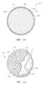
- the golf ball 10 includes a central core 12 which may be solid or liquid as known in the art.
- a cover 14 is surroundingly disposed about the central core 12 .
- An intermediate layer 16 may be present between the central core 12 and the cover 14 .
- the present invention primarily relates to the cover 14 and will be described with particular reference thereto, but it is also contemplated to apply to molding of the intermediate layer 16 .
- the preferred embodiment ball 10 includes one or more deep dimples 18 that extend through at least the cover layer 14 .
- the deep dimples 18 extend to, or through, the intermediate layer 16 .
- the deep dimples may further extend into the core 12 . It will be appreciated that in the event the core is liquid, the deep dimples will not extend to the core.
- the present invention relates to various molding assemblies and techniques for forming a golf ball having one or more deep dimples along an outer surface of the golf ball.
- the deep dimples extend through the outermost cover layer of the ball, to or into or through one or more components underneath the outermost cover layer.
- the deep dimples result from one or more outwardly extending projections or protrusions that are provided in a molding chamber used for molding the final ball.
- the protrusions generally have a height greater than other raised regions along the molding surface that form conventional dimples along the ball exterior.
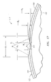
- FIG. 2 a perspective view of a preferred embodiment molding assembly in accordance with the current invention is shown.
- the preferred embodiment molding assembly 20 provides such mixing as a result of its unique design and configuration.
- An injection machine as known in the art, is connected to the preferred embodiment molding assembly 20 which comprises an upper half 22 A and a lower half 22 B.
- the upper and lower halves 22 A and 22 B are preferably formed from a metal or suitable material.
- a mixing chamber may, as known in the art, precede the molding assembly 20 if desired.
- the molding assembly 20 is utilized as follows.
- a core 12 (referring to FIG.
- each of the hemispherical cavities 24 A and 24 B defines a plurality of raised regions that, upon molding a cover layer therein, will result in corresponding dimples on the cover layer.
- Each upper and lower half 22 A and 22 B of the preferred embodiment molding assembly 20 defines an adapter portion 26 A and 26 B to enable the molding assembly 20 to connect to other process equipment as mentioned above and leads to a material inlet channel 28 A and 28 B as illustrated in FIG. 2 .
- the separate halves of adapter portion 26 A and 26 B are aligned with each other and create a material flow inlet within the molding assembly.
- each upper and lower half 22 A and 22 B of the assembly 20 further defines flow channels 28 A and 28 B, 30 A and 30 B and 32 A and 32 B which create a comprehensive flow channel within the molding assembly when the upper and lower halves 22 A and 22 B are closed.
- the material flow inlet channel portion 28 A, 28 B receives the constituent materials from the adapter portion 26 A and 26 B and directs those materials to a turbulence-promoting portion of the channel 30 A, 30 B which is configured to form at least one fan gate.
- the upper and lower mold halves 22 A and 22 B include complimentary turbulence-promoting peanut after-mixer channel portions 30 A and 30 B, respectively. It will be appreciated that upon closing the upper and lower halves 22 A and 22 B of the molding assembly 20 , the channel portion 30 A and 30 B defines a region of the flow channel that is generally nonlinear and includes a plurality of bends and at least one branching intersection generally referred to herein as an after-mixer gate.
- Each after-mixer channel portion 30 A, 30 B is designed to direct material flow along an angular or tortuous path. As will be described in more detail below, when material reaches a terminus of angular flow in one plane of the flow channel in one half, the material flows in a transverse manner to a corresponding after-mixer channel portion in the opposing half. Thus, when the constituent materials arrive at the after-mixer defined by the channel portion 30 A and 30 B, turbulent flow is promoted, forcing the materials to continue to mix within the molding assembly 20 . This mixing within the molding assembly 20 provides for improved overall mixing of the constituent materials, thereby resulting in a more uniform and homogeneous composition for the cover 14 .
- FIGS. 3 and 4 views 3 - 3 and 4 - 4 from FIG. 2 , respectively, are provided. These views illustrate additional details of the present invention as embodied in the mold upper and lower halves 22 A and 22 B.
- the material inlet channel 28 A and 28 B allows entry of the constituents which are subsequently directed through the mix-promoting channel portion 30 A and 30 B, which forms the after-mixer, then through the connecting channel portion 32 A and 32 B and to the fan gate portion 34 A and 34 B which leads into the cavity 24 A and 24 B.
- the final channel portion 34 A and 34 B may be defined in several forms extending to the cavity 24 A and 24 B, including corresponding or complimentary paths which may be closed ( 34 A) or open ( 34 B) and of straight, curved or angular ( 34 A, 34 B) shape.
- At least one protrusion 36 preferably extends into the central cavity 24 A and 24 B.
- This at least one protrusion extends from the molding surface into the molding cavity 24 A and 24 B and supports a golf ball core, such as core 12 , or intermediate ball assembly.
- a golf ball core such as core 12 , or intermediate ball assembly.
- the preferred dimensions, configuration, and orientation of the protrusion(s) are explained in greater detail herein. It is these protrusion(s) that form one or more deep dimple(s) in the outer surface of a golf ball and which relate to another aspect of the present invention.
- many retractable pins often four, six or more, are used to centrally position and retain the core 12 in the molding cavity.
- fewer supporting structures are necessary in the molding assembly 20 to centrally locate the core 12 in the central cavity 24 A and 24 B.
- only three protrusions 36 or less may be necessary per mold half.
- the use of fewer supporting structures reduces the cost of the tooling and reduces problems such as defacement and surface imperfections caused by retractable pins.
- the protrusions 36 are preferably provided at different locations in the molding assembly 20 and extend into different portions of the central cavity formed by the hemispherical cavities 24 A, 24 B.
- a channel leading from the cavity 24 A and 24 B may be provided as either a cavity venting channel or an overflow channel or dump well as known in the art.
- a dump well 31 A, 31 B is provided in the corresponding molds.
- a dump well vent 33 A, 33 B provides communication between the dump well and mold exterior.
- a venting channel 29 A, 29 B is defined in the molds and provides communication between the central cavity 24 A, 24 B and the dump well. It will be appreciated that when the upper and lower halves 22 A and 22 B are closed, the respective portions of the channel align with one another to form the venting or overflow channel.
- FIG. 5 a perspective view of the molding assembly 20 illustrates the details of material flow and mixing provided by the current invention.
- the body halves 22 A and 22 B are shown in an open position, i.e., removed from one another, for purposes of illustration only. It will be appreciated that the material flow described below takes place when the halves 22 A and 22 B are closed.
- the adapter portion 26 A, 26 B leads to the inlet flow channel 28 A, 28 B which typically has a uniform circular cross section of 3608 .
- the flowing material proceeds along the inlet channel 28 A, 28 B until it arrives in a location approximately at a plane designated by line C-C. At this region, the material is forced to split apart by a branching intersection 38 A and 38 B.
- Each half of the branching intersection 38 A and 38 B is divergent, extending in a direction generally opposing the other half. For example, portion 38 A extends upward and 38 B extends downward relative to the inlet channel 28 A, 28 B as shown.
- Each half of the branching intersection 38 A and 38 B in the illustrated embodiment, is semicircular, or about 1808 in curvature. The separated material flows along each half of the branching intersection 38 A and 38 B until it reaches a respective wall, 40 A and 40 B.
- the material can no longer continue to flow within the plane of the closed mold, i.e., the halves 22 A and 22 B being aligned with one another.
- the upper half 22 A is oriented downward (referring to FIG. 5 ) so that it is generally parallel with the lower half 22 B.
- the orientation of the halves 22 A and 22 B in such a closed configuration is referred to herein as lying in an x-y plane.
- the configuration of the present invention after-mixer provides one or more flow regions that are transversely oriented to the x-y plane of the closed mold. Hence, these transverse regions are referred to as extending in a z direction.
- each first convergent portion is parallel to each first diverging branching intersection to promote a smooth material transfer.
- the portion 42 A is parallel to the portion 38 A
- the portion 42 B is parallel to the portion 38 B.
- the flowing material arrives at the first common area 44 A and 44 B, which has a full circular, i.e., 360 degrees, cross section when the halves 22 A and 22 B are closed. Essentially, the previously separated material is rejoined in the first common area 44 A and 44 B. A second branching intersection 46 A and 46 B which is divergent then forces the material to split apart a second time and flow to each respective second wall 48 A and 48 B. As with the first wall 40 A and 40 B, the material, upon reaching the second wall 48 A and 48 B can no longer flow in an x-y plane and must instead move in a transverse z-direction.
- the material flows from a point “2 in one half 22 A to a corresponding point” 2 in the other half 22 B, which lies in a second convergent portion 50 B.
- the material reaching the wall 48 B flows from a point $2 in one half 22 B to a corresponding point $2 in the other half 22 A, which lies in a second convergent portion 50 A.
- each second convergent portion 50 A and 50 B is parallel to each second diverging branching intersection 46 A and 46 B.
- the portion 50 A is parallel to the portion 46 A and the portion 50 B is parallel to the portion 46 B.
- the second convergent portion 50 A and 50 B forces the material into a second common area 52 A and 52 B to once again rejoin the separated material.
- the second common area 52 A and 52 B has a full circular cross section.
- a third branching intersection 54 A and 54 B again diverges, separating the material and conveying it in different directions.
- the material is forced to again flow in a transverse, z-direction from the planar x-y direction.
- the material flows to a corresponding point 3 in the other half 22 B, which lies in a third convergent portion 58 B.
- the material flows to a corresponding point 3 in the other half 22 A, which is in a third convergent portion 58 A.
- the turbulence-promoting after-mixer structure 30 A and 30 B ends with a third convergent portion 58 A and 58 B returning the separated material to the connecting flow channel 32 A and 32 B.
- the connecting channel 32 A and 32 B is a common, uniform circular channel having a curvature of 360 degrees. Once the material enters the connecting channel portion 32 A and 32 B, typical straight or curved smooth linear flow recommences.
- the present invention provides for increased mixing of constituent materials.
- mixing is encouraged and controlled while the flow remains uniform, reducing back flow or hanging-up of material, thereby reducing the degradation often involved in non-linear flow.
- Particular note is made of the angles of divergence and convergence of the after-mixer portions 38 A and 38 B, 42 A and 42 B, 46 A and 46 B, 50 A and 50 B, 54 A and 54 B and 58 A and 58 B, as each extends at the angle of about 30 degrees to 60 degrees from the centerline of the linear inlet flow channel 28 A, 28 B. This range of angles allows for rapid separation and re-convergence while minimizing back flow.
- each divergent branching portion and converging portion 38 A and 38 B, 42 A and 42 B, 46 A and 46 B, 50 A and 50 B, 54 A and 54 B and 58 A and 58 B extends from the centerline of the linear inlet flow channel 28 A, 28 B for a distance of one to three times the diameter of the channel 28 A, 28 B before reaching its respective wall 40 A and 40 B, 48 A and 48 B and 56 A and 56 B.
- the common areas 44 A and 44 B and 52 A and 52 B are directly centered about a same linear centerline which extends from the inlet flow channel portion 28 A, 28 B to the commencement of the connecting flow channel portion 32 A, 32 B.
- the common areas 44 A and 44 B and 52 A and 52 B are aligned linearly with the channel portions 28 A, 28 B and 32 A, 32 B, providing for more consistent, uniform flow. While several divergent, convergent, and common portions are illustrated, it is anticipated that as few as one divergent and convergent portion or as many as ten to twenty divergent and convergent portions may be used, depending upon the application and materials involved.
- FIG. 6 depicts the turbulence-promoting after-mixer channels 30 A, 30 B from a side view when the molding assembly 20 is closed.
- the upper half 22 A and the lower half 22 B meet, thereby creating the turbulence-promoting after-mixer along the region of the channel portions 30 A and 30 B.
- the resulting flow pathway causes the constituent materials flowing therethrough to deviate from a straight, generally linear path to a nonlinear turbulence-promoting path.
- the interaction and alignment of the divergent branching intersections 38 A and 38 B, 46 A and 46 B, 54 A and 54 B (referencing back to FIG. 5 ), the convergent portions 42 A and 42 B, 50 A and 50 B, 58 A and 58 B, and the common portions 44 A and 44 B, and 52 A and 52 B, also as described above, is shown in detail.
- the after-mixer includes a plurality of bends or arcuate portions that cause liquid flowing through the fan gate to not only be directed in the same plane in which the flow channel lies, but also in a second plane that is perpendicular to the first plane. It is most preferable to utilize an after-mixer with bends such that liquid flowing therethrough travels in a plane that is perpendicular to both the previously noted first and second planes. This configuration results in relatively thorough and efficient mixing due to the rapid and changing course of direction of liquid flowing therethrough.
- the configuration of the mold channels may take various forms. One such variation is shown in FIG. 7 . Reference is made to the lower mold half 22 B for the purpose of illustration, and it is to be understood that the upper mold half 22 A (not shown) comprises a complimentary configuration.
- the adapter portion 26 B leads to the inlet flow channel 28 B which leads to the turbulence-promoting channel portion 30 B. However, instead of the adapter 26 B and the channels 28 B and 30 B being spaced apart from the central cavity 24 B, they are positioned approximately in line with the central cavity 24 B, eliminating the need for the connecting channel portion 32 B to be of a long, curved configuration to reach the fan gate portion 34 B.
- the connecting channel 32 B is a short, straight channel, promoting a material flow path which may be more desirable for some applications.
- the flow channels and the central cavity may be arranged according to other forms similar to those shown, which may occur to one skilled in the art, as equipment configurations and particular materials and applications dictate.
- FIG. 7 also illustrates one or more nonretractable protrusions 36 in the molding chamber.
- the channels 30 A and 30 B are depicted as each comprising a plurality of angled bends or turns.
- the channels are not limited to the angled bend-type fan gate configuration and include any turbulence-promoting design located in a region 59 B between the adapter portion 26 B and the cavity 24 B.
- the channels in the turbulence-promoting region 59 A (not shown) and 59 B could be formed to provide one or more arcuate regions such that upon closure of the upper and lower mold halves 22 A and 22 B, the flow gate has, for example, a spiral or helix configuration.
- the shape of the resulting flow gate insures that the materials flow through the turbulence-promoting region and thoroughly mix with each other, thereby reducing typical straight laminar flow and minimizing any settling in a low-flow area where degradation of flow may occur.
- the shape and configuration of the flow channel is such that the velocity of the materials flowing therethrough is generally constant at different locations along the channel. And, as previously noted, such flow characteristics and thorough mixing of the materials has been found to lead to greater consistency and uniformity in the final physical properties and characteristics of the resulting golf ball layer or component.
- FIG. 8 further illustrates one or more protrusions 36 in the molding chamber.
- the turbulence-promoting region 59 A (not shown) and 59 B may be placed in various locations in the upper and lower mold halves 22 A (not shown) and 22 B.
- the turbulence-promoting region 59 B and the other flow channel portions 28 B, 32 B, and 34 B may be arranged so as to create an approximately straight layout between the adapter portion 26 B and the central cavity 24 B.
- FIG. 9 also illustrates one or more protrusions 36 in the molding chamber.
- Venting of central cavity 24 A, 24 B reduces voids by removing these gases.
- a cover 14 is provided that is significantly more free from voids or other imperfections than a cover produced by a non-vented RIM process.
- a preferred method of making a golf ball in accordance with the present invention is illustrated in FIG. 10 .
- a golf ball core 12 made by techniques known in the art is obtained, illustrated as step 70 .
- the core 12 is preferably positioned within a mold having venting provisions, after-mixers, and fan gates as described herein. This is illustrated as step 72 . It is preferred that the core 12 is supported on a plurality of the previously described protrusions 36 that form deep dimples in the final ball. This is shown as step 74 .
- the mold is then closed. This is illustrated as step 75 .
- the cover layer 14 is molded over the core 12 by RIM as step 76 . If venting of gases from the molding cavity is desired, such gases are preferably vented as previously described. This is designated as step 78 . Should increased removal of gases be desired, the venting of step 78 is enhanced by providing a vacuum connection as known in the art to the venting channel.
- the golf ball 10 is removed from the mold, as shown by steps 79 and 80
- the preferred embodiment molding processes described herein may utilize one or more mold release agents to facilitate removal of the molded layer or component from the mold.
- a golf ball manufactured according the preferred method described herein exhibits unique characteristics.
- Golf ball covers made through compression molding and traditional injection molding include balata, ionomer resins, polyesters resins and polyurethanes. The selection of polyurethanes which can be processed by these methods is limited. Polyurethanes are often a desirable material for golf ball covers because balls made with these covers are potentially more resistant to scuffing and resistant to deformation than balls made with covers of other materials.
- the current invention allows processing of a wide array of grades of polyurethane through RIM which was not previously possible or commercially practical utilizing either compression molding or traditional injection molding.
- urethane resins such as Bayer® MP-7500, Bayer® MP-5000, Bayer® aliphatic or light stable resins, and Uniroyal® aliphatic and aromatic resins may be used.
- Bayer® MP-7500 Bayer® MP-5000
- Bayer® aliphatic or light stable resins Bayer® aliphatic or light stable resins
- Uniroyal® aliphatic and aromatic resins may be used.
- Bayer® MP-10000 polyurethane resin a golf ball with the properties described below has been provided.
- BASF aromatic or aliphatic resins may be used.
- a traditional golf ball cover typically has a total thickness in the range of about 0.060 inches to 0.080 inches.
- a golf ball of the present invention may utilize a cover having a thickness of from about 0.002 inches to about 0.100 inches, more preferably from about 0.005 inches to about 0.075 inches, more preferably from about 0.010 inches to about 0.050 inches, and most preferably from about 0.015 inches to about 0.050 inches. This reduced cover thickness is often a desirable characteristic. It is contemplated that thinner layer thicknesses are possible using the present invention.
- an outer cover or any other layer of the present invention golf ball is more dependably concentric and uniform with the core of the ball, thereby improving ball performance. That is, a more uniform and reproducible geometry is attainable by employing the present invention.
- the present invention also provides a golf ball in which at least one cover or core layer is a fast-chemical-reaction-produced component.
- This component comprises at least one material selected from the group consisting of polyurethane, polyurea, polyurethane ionomer, epoxy, and unsaturated polyesters, and preferably comprises polyurethane.
- the invention also includes a method of producing a golf ball which contains a fast-chemical-reaction-produced component.
- a golf ball formed according to the invention preferably has a flex modulus in the range of from about 5 to about 310 kpsi, a Shore D hardness in the range of from about 20 to about 90, and good durability.
- Particularly preferred forms of the invention also provide for a golf ball with a fast-chemical-reaction-produced cover having good scuff resistance and cut resistance.
- polyurethane and/or polyurea is expressed as “polyurethane/polyurea”.
- a particularly preferred form of the invention is a golf ball with a cover comprising polyurethane, the cover including from about 5 to about 100 weight percent of polyurethane formed from recycled polyurethane.
- the method of the invention is particularly useful in forming golf balls because it can be practiced at relatively low temperatures and pressures.
- the preferred temperature range for the method of the invention is from about 50 EF to about 250EF and preferably from about 120 EF to about 180 EF when the component being produced contains polyurethane.
- Preferred pressures for practicing the invention using polyurethane-containing materials are 200 psi or less and more preferably 100 psi or less.
- the method of the present invention offers numerous advantages over conventional slow-reactive process compression molding of golf ball covers.
- the method of the present invention results in molded covers in a demold time of 10 minutes or less. An excellent finish can be produced on the ball.
- the method of the invention also is particularly effective when recycled polyurethane or other polymer resin, or materials derived by recycling polyurethane or other polymer resin, is incorporated into the product.
- the fast-chemical-reaction-produced component can be one or more cover and/or core layers of the ball.
- a polyurethane cover is formed according to the invention, and is then covered with a polyurethane top coat, excellent adhesion can be obtained.
- the adhesion in this case is better than adhesion of a polyurethane coating to an ionomeric cover.
- This improved adhesion can result in the use of a thinner top coat, the elimination of a primer coat, and the use of a greater variety of golf ball printing inks beneath the top coat.
- typical inks such as one component polyurethane inks and two component polyurethane inks.
- the preferred method of forming a fast-chemical-reaction-produced component for a golf ball according to the invention is by RIM.
- highly reactive liquids are injected into a closed mold, mixed usually by impingement and/or mechanical mixing and secondarily mixed in an in-line device such as a peanut mixer, where they polymerize primarily in the mold to form a coherent, one-piece molded article.
- the RIM processes usually involve a rapid reaction between one or more reactive components such as polyether—or polyester—polyol, polyamine, or other material with an active hydrogen, and one or more isocyanate—containing constituents, often in the presence of a catalyst.
- the constituents are stored in separate tanks prior to molding and may be first mixed in a mix head upstream of a mold and then injected into the mold.
- the liquid streams are metered in the desired weight to weight ratio and fed into an impingement mix head, with mixing occurring under high pressure, e.g., 1500 to 3000 psi.
- the liquid streams impinge upon each other in the mixing chamber of the mix head and the mixture is injected into the mold.
- One of the liquid streams typically contains a catalyst for the reaction.
- the constituents react rapidly after mixing to gel and form polyurethane polymers. Polyureas, epoxies, and various unsaturated polyesters also can be molded by RIM.
- RIM differs from non-reaction injection molding in a number of ways.
- the main distinction is that in RIM a chemical reaction takes place in the mold to transform a monomer or adducts to polymers and the components are in liquid form.
- a RIM mold need not be made to withstand the pressures which occur in a conventional injection molding.
- injection molding is conducted at high molding pressures in the mold cavity by melting a solid resin and conveying it into a mold, with the molten resin often being at about 150 to about 350 EC. At this elevated temperature, the viscosity of the molten resin usually is in the range of 50,000 to about 1,000,000 centipoise, and is typically around 200,000 centipoise.
- the solidification of the resins occurs after about 10 to 90 seconds, depending upon the size of the molded product, the temperature and heat transfer conditions, and the hardness of the injection molded material. Subsequently, the molded product is removed from the mold. There is no significant chemical reaction taking place in an injection molding process when the thermoplastic resin is introduced into the mold. In contrast, in a RIM process, the chemical reaction typically takes place in less than about 2 minutes, preferably in under one minute, and in many cases in about 30 seconds or less.
- the present invention is believed to provide for improved durability of a golf ball cover layer by providing a uniform or seamless cover in which the properties of the cover material in the region along the parting line are generally the same as the properties of the cover material at other locations on the cover, including at the poles.
- the improvement in durability is believed to be a result of the fact that the reaction mixture is distributed uniformly into a closed mold.
- This uniform distribution of the injected materials reduces or eliminates knit-lines and other molding deficiencies which can be caused by temperature difference and/or reaction difference in the injected materials.
- the process of the invention results in generally uniform molecular structure, density and stress distribution as compared to conventional injection-molding processes.
- the fast-chemical-reaction-produced component has a flex modulus of from about 1 to about 310 kpsi, more preferably from about 1 to about 100 kpsi, and most preferably from about 2 to about 50 kpsi.
- the subject component can be a cover with a flex modulus which is higher than that of the centermost component of the cores, as in a liquid center core and some solid center cores.
- the fast-chemical-reaction-produced component can be a cover with a flex modulus that is higher than that of the immediately underlying layer, as in the case of a wound core.
- the core can be one piece or multi-layer, each layer can be either foamed or unfoamed, and density adjusting fillers, including metals, can be used.
- the cover of the ball can be harder or softer than any particular core layer.
- the fast-chemical-reaction-produced component can incorporate suitable additives and/or fillers.
- suitable additives and/or fillers When the component is an outer cover layer, pigments or dyes, accelerators and UV stabilizers can be added. Examples of suitable optical brighteners which probably can be used include Uvitex® and Eastobrite® OB-1. An example of a suitable white pigment is titanium dioxide. Examples of suitable and UV light stabilizers are provided in commonly assigned U.S. Pat. No. 5,494,291. Fillers which can be incorporated into the fast-chemical-reaction-produced cover or core component include those listed below in the definitions section.
- compatible polymeric materials can be added. For example, when the component comprises polyurethane and/or polyurea, such polymeric materials include polyurethane ionomers, polyamides, etc.
- a golf ball core layer formed from a fast-chemical-reaction-produced material according to the present invention typically contains 0 to 20 weight percent of such filler material, and more preferably 1 to 15 weight percent.
- the additives typically are selected to control the density, hardness and/or COR.
- a golf ball inner cover layer formed from a fast-chemical-reaction-produced material according to the present invention typically contains 0 to 60 weight percent of filler material, more preferably 1 to 30 weight percent, and most preferably 1 to 20 weight percent.
- a golf ball outer cover layer formed from a fast-chemical-reaction-produced material according to the present invention typically contains 0 to 20 weight percent of filler material, more preferably 1 to 10 weight percent, and most preferably 1 to 5 weight percent.
- Catalysts can be added to the RIM polyurethane system starting materials as long as the catalysts generally do not react with the constituent with which they are combined.
- Suitable catalysts include those which are known to be useful with polyurethanes and polyureas.
- the reaction mixture viscosity should be sufficiently low to ensure that the empty space in the mold is completely filled.
- the reactant materials generally are preheated to about 80 EF to about 200 EF and preferably to 100 EF to about 180 EF before they are mixed. In most cases it is necessary to preheat the mold to, e.g., from about 80 EF to about 200 EF, to provide for proper injection viscosity.
- one or more cover layers of a golf ball can be formed from a fast-chemical-reaction-produced material according to the present invention.
- the golf ball 110 includes a polybutadiene core 112 and a polyurethane cover 114 formed by RIM.
- the golf ball 110 defines a plurality of dimples 116 along its outer surface.
- the ball 110 also defines one or more deep dimples 118 as described in greater detail herein.
- the golf ball 110 having a core comprising a RIM polyurethane is shown.
- the golf ball 110 has a RIM polyurethane core 112 , and a RIM polyurethane cover 114 .
- the golf ball 110 defines a plurality of dimples 116 along its outer surface.
- the ball 110 also defines one or more deep dimples 118 as described in greater detail herein.
- a multi-layer golf ball 210 is shown with a solid core 212 containing recycled RIM polyurethane, a mantle cover layer comprising RIM polyurethane 213 , and an outer cover layer 214 comprising ionomer or another conventional golf ball cover material.
- Non-limiting examples of multi-layer golf balls according to the invention with two cover layers include those with RIM polyurethane mantles having a thickness of 0.01 to 0.20 inches, or thinner, and a Shore D hardness of 20 to 80, covered with ionomeric or non-ionomeric thermoplastic, balata or other covers having a Shore D hardness of 20 to 80 and a thickness of 0.010 to 0.20 inches.
- the golf ball 210 defines a plurality of dimples 216 along its outer surface.
- the ball 210 also defines one or more deep dimples 218 as described in greater detail herein.
- one or more of the deep dimples 120 extend into the core 112 disposed underneath the cover layer 114 . These dimples are herein referred to as deep dimples.
- the preferred embodiment golf ball 210 shown in FIGS. 13 and 14 comprises a core 212 having an inner cover layer 213 disposed thereon and an outer cover layer 214 formed about the inner cover layer 213 .
- the cover layers 213 and 214 define a plurality of dimples 216 along the outer surface of the outer cover layer 160 .
- One or more of the dimples, and preferably two or more of the dimples, and more preferably three or more of the dimples per hemisphere, extend entirely through the outer cover layer 214 and at least partially into or to the inner cover layer 213 .
- These dimples, which extend through the outer cover layer are again referred to herein as deep dimples and shown in FIG. 13 as dimples 218 .
- the deep dimples can be circular, non-circular, a combination of circular and non-circular, or any other shape desired. They may be of the same or differing shape, such as a circular larger dimple having an oval smaller dimple within the circular dimple, or an oval larger dimple having a circular or other shape within the larger dimple.
- the dimples do not have to be symmetrical.
- FIG. 13 illustrates deep dimple 220 formed in both the inner cover layer and the outer cover layer.
- the inner portion of the dimple 220 is formed in the inner cover layer 213
- the outer portion of the dimple 220 is formed in the outer cover layer 214 .
- dimples may be formed in the core and the single cover layer in the same way as previously described. Additionally, dimples may be formed in more than two cover and/or core layers if desired.
- a multi-layer golf ball is produced that has one or more deep dimples that protrude into the ball through at least one layer, such as an outer cover layer.
- the deep dimple protrudes through at least two layers.
- the dimples of the at least two layers are configured with the same geometric coordinates (that is, the approximate center of the both dimples would be in the same location, and so the dimples are concentric with respect to each other), producing a golf ball having a dimpled layer over a dimpled layer. This allows for much thinner layers with traditional dimples.
- the dimples of one or more inner layers may be of varying depths, diameters and radii, yet still aligned with the dimples of the outer layer. This also allows for a dimple within a dimple, where there is a smaller dimple in at least one inner or mantle layer that is within a larger diameter dimple in the outer layer, such as the dimples shown in FIGS. 15 to 18 .
- FIGS. 15 to 18 illustrate a deep dimple that is a dual radius dimple, or a dimple within a dimple.
- a dual radius dimple is that the deeper part of the dual radius may be filled in with a coating or other material. This provides an effective method for forming dimple depths to a desired value as compared to other methods of dimple formation.
- the dimple shape may be any shape desired, and each dimple may be the same or different shape.
- the depth of the second or deepest portion of the dual radius dimple may be expressed as a percentage of the total depth of the dimple.
- the region or portion of the dimple which extends to the outermost surface of the ball may be referred to herein as the “major” dimple.
- the portion of the dimple which extends to the deepest portion or depth of the dimple can be referred to herein as the “minor” dimple.
- the preferred depth of the major dimple is approximately from about 40% to about 80% of the overall dimple depth.
- the preferred depth of the minor dimple is approximately 20% to about 60% of the overall dimple depth. The depth being measured from the chord of the major dimple to the bottom of the minor dimple.
- the preferred diameter of the minor dimple is from about 10% to about 70% of the diameter of the major dimple.
- FIG. 15 is a cross-sectional detail illustrating a portion of a preferred embodiment golf ball produced in accordance with the present invention.
- This preferred embodiment golf ball 310 comprises a core 320 having a cover layer 330 formed thereon.
- the cover layer defines at least one deep dimple 340 along its outer surface 335 .
- one or more (preferably two or more, more preferably three or more per hemisphere) of the dimples extends entirely through the cover layer and into the core disposed underneath the cover layer.
- FIG. 15 illustrates a deep dimple defined by two different curvatures. Referring to FIG.
- a first radius R 1 defines the portion of the dimple from the outer surface 335 of the golf ball 310 to a point at which the deep dimple extends into a layer underneath the cover layer. At this point, the curvature of the dimple changes and is defined by radius R 2 .
- R 1 is from about 0.130 inches to about 0.190 inches, and most preferably, R 1 , is from about 0.140 to about 0.180 inches.
- R 1 ranges from about 0.100 inches to about 1.000 inch, and most preferably from about 0.200 inches to about 0.800 inches.
- R 2 is from about 0.025 inches to about 0.075 inches, and most preferably, R 2 is about 0.050 to about 0.065 inches.
- R 2 ranges from about 0.002 inches to about 0.500 inches, and most preferably from about 0.010 inches to about 0.200 inches.
- the overall diameter or span of the dimple 340 is designated herein as D 1 .
- the diameter or span of the portion of the dimple that extends into the layer underneath the outer cover layer is designated herein as D 2 .
- D 1 is from about 0.030 inches to about 0.250 inches, more preferably from about 0.100 inches to about 0.186 inches, and most preferably, D 1 is about 0.146 inches to about 0.168 inches.
- D 1 ranges from about 0.100 inches to about 0.250 inches, and most preferably D 1 is about 0.140 inches to about 0.180 inches.
- D 2 is from about 0.020 inches to about 0.160 inches, more preferably from about 0.030 inches to about 0.080 inches, and most preferably, D 2 is about 0.056 inches.
- D 2 is from about 0.040 inches to about 0.060 inches.
- the overall depth of the deep dimple portion that is defined by R 1 is designated herein as H 1 and the depth or portion of the dimple that is defined by R 2 is designated herein as H 2 .
- H 1 is from about 0.005 inches to about 0.135 inches, more preferably from about 0.005 to about 0.025 inches, more preferably from about 0.010 inches to about 0.015 inches, and most preferably, H 1 is about 0.015 inches.
- H 1 is from about 0.005 inches to about 0.015 inches.
- H 2 may range from about 0.005 inches to about 0.135 inches, and more preferably from about 0.005 to about 0.050 inches.
- H 2 ranges from about 0.005 inches to about 0.030 inches and is about 0.010 inches.
- H 2 is from about 0.005 inches to about 0.015 inches.
- a golf ball 410 comprises a core 420 and a cover layer 430 formed thereon.
- the cover layer 430 defines at one deep dimple 440 along the outer surface 435 of the golf ball 410 .
- the dimple 440 is defined by two different curvatures, each of which is defined by radii R 2 and R 1 as previously described with respect to FIG. 15 .
- the other parameters D 1 , D 2 , H 1 , and H 2 are as described with respect to FIG. 15 .
- FIG. 16 illustrates an embodiment in which the dimple 440 extends to the core 420 and not significantly into the core.
- the version illustrated in FIG. 15 is directed to a dimple configuration in which a dimple extends significantly into the underlying core.
- FIG. 17 illustrates a preferred embodiment golf ball 510 comprising a core 520 , a mantle or inner cover layer 550 , and an outer cover layer 560 .
- the outer cover layer 560 and inner cover layer 550 define at least one deep dimple 540 along the outer surface 535 of the ball 510 .
- the dimple 540 is defined by two different regions or two curvatures, each of which is in turn defined by radii R 2 and R 1 .
- the other parameters D 1 , D 2 , H 1 , and H 2 are as described with respect to FIG. 15 .
- the dimple 540 extends entirely through the outer cover layer 560 and into the inner cover layer or mantle layer 550 .
- FIG. 18 illustrates another preferred embodiment golf ball 610 in accordance with the present invention.
- the golf ball 610 comprises a core 620 having disposed thereon an inner cover layer or mantle layer 650 and an outer cover layer 660 .
- Defined along the perimeter or outer periphery of the ball 610 is at least one deep dimple 640 .
- the dimple 640 is defined along the outer surface 635 of the ball 610 .
- the dimple 640 has two different regions or curvatures each defined by radii R 2 and R 1 .
- the other parameters D 1 , D 2 , H 1 , and H 2 are as described with respect to FIG. 15 .
- the version illustrated in FIG. 18 reveals a dimple 640 that does not significantly extend into the mantle layer or inner cover layer 650 . Instead, the dimple 640 only extends to the outermost region of the mantle layer or inner cover layer 650 .
- the volume ratio is the sum of the volume of all dimples taken below a chord extending across the top of a dimple, divided by the total volume of the ball.
- the volume ratio is a critical parameter for ball flight. A high volume ratio generally results in a low flying ball. And a low volume ratio often results in a high-flying ball. A preferred volume ratio is about 1%.
- the balls of the present invention however may be configured with greater or lesser volume ratios.
- a typical coverage for a ball of the present invention is about 60% to about 90% and preferably about 83.8%. In other embodiments, this preferred coverage is about 84% to about 85%. These percentages are the percent of surface area of the ball occupied by dimples. It will be appreciated that the present invention golf balls may exhibit coverages greater or less than that amount.
- dimple within a dimple there is less impact on the volume ratio than the use of deep dimples. If there are enough of either dimples within dimples or deep dimples, the aerodynamics of the ball will eventually be impacted.
- the optimum or preferred number of deep dimples utilized per ball varies. It is the amount necessary to secure or center the core or core and cover layer(s) during molding without adversely affecting the aerodynamics of the finished ball.
- the present invention includes the use of a relatively large number of deep dimples. That is, although most of the focus of the present invention is directed to the use of only a few deep dimples per golf ball, i.e. from 2 to 6, the invention includes the use of a significantly greater number such as from about 50 to about 250. It is also contemplated that for some applications, it may be desirable to form all, or nearly all, dimples on a golf ball as deep dimples such as, for example, from about 50 to about 500.
- the proportion selected may depend upon aesthetics, aerodynamic effects, marketability factors, ball performance, manufacturing, or other factors.
- the proportion of dimples that may be formed as deep dimples may be all, substantially all, a majority, half, a minority, or a minor number.
- the molding equipment employed to form such balls utilizes a molding chamber having a molding surface with a corresponding number of outwardly extending protuberances or projections as described herein.
- the processes and equipment described herein for reaction injecting molding a polyurethane or polyurethane derivative material are well suited for forming a golf ball with a relatively large proportion of deep dimples.
- the mixing and molding characteristics of the molding material and that associated with the process and equipment enable and promote the formation of one or more cover layers that define a large number of well defined deep dimples.
- One particularly preferred embodiment golf ball includes multiple populations of dimples along its outer surface. For example, two, three, four, five, six or more different types or populations of dimples may be provided. One or more of the multiple populations are preferably deep dimples. The other populations may include a wide array of dimple types such as, but not limited to, conventional dimples, non-conventional dimples, or dimples known in the prior art.
- the ball will fly lower as compared to the use of dimples that are shallower. As the number of deep dimples increases, the ball will exhibit a lower flight trajectory. Accordingly, the preferred approach is to utilize a smaller number of deep dimples. However, for other applications, the present invention includes a ball with many deep dimples.
- the overall shape of the dimples may be nearly any shape.
- shapes such as hexagon, pentagon, triangle, ellipse, circle, etc. are all suitable. There is no limit to the number of shapes, although some shapes are preferred over others. At present, circular dimples are preferred.
- the dimples may utilize any geometry. For instance, dimples may be defined by a constant curve or a multiple curvature or dual radius configuration or an elliptical or teardrop shaped region.
- FIG. 19 illustrates a preferred embodiment molding apparatus 1000 in accordance with the present invention.
- Molding apparatus 1000 comprises two mold halves 1020 and 1040 that each define a hemispherical portion of a molding chamber 1024 and 1044 .
- Defined along the outer surface of the hemispherical portion of the molding chamber 1024 are a plurality of raised protrusions or support pins 1032 . These raised regions or support pins form dimples in a cover layer in a golf ball formed using molding apparatus 1000 .
- Also provided along the outer surface of the hemispherical molding chamber 1024 are a plurality of outwardly extending or raised regions or support pins 1026 , 1028 , and 1030 .
- the raised regions are of a height greater than the height of the raised regions 1032 .
- the raised regions 1026 , 1028 , and 1030 form deep dimples as described herein. These raised regions are used to retain and support a golf ball core placed in the mold. These raised regions also serve to form deep dimples 1018 in the golf ball 1010 .
- a passage 1022 is provided in the mold half 1020 as will be appreciated. The passage 1022 provides communication and a path for a flowable moldable material to be introduced into the molding chamber.
- the molding apparatus 1000 also includes a second molding portion or plate 1040 .
- the plate 1040 defines a hemispherical molding chamber 1044 also having a plurality of raised regions or support pins along its outer surface.
- raised regions 1046 and 1048 are provided similar to the previously described raised regions 1026 , 1028 , and 1030 .
- the molding plate 1040 also defines a channel 1042 extending from the molding chamber 1044 to the exterior of the plate. Most preferably, the molding channel 1042 is aligned with channel 1022 in the other plate 1020 when the mold is closed to provide a unitary passage providing communication between the molding chamber and the exterior of the mold. It will be appreciated that this figure is not necessarily to scale, and so channel 1042 would likely be significantly smaller in a commercial manufacturing application.
- a turbulence-inducing after-mixer is provided in the mold halves as previously described in conjunction with FIGS. 2-9 .
- a golf ball core placed in the molding chamber 1024 , 1044 is supported by the various raised regions 1026 , 1028 , 1030 , 1046 , and 1048 as previously described.
- the golf ball 1010 is produced.
- Certain preferred embodiment molding equipment in accordance with the present invention utilize molds with molding surfaces that provide a collection of different types or heights of raised regions or outwardly extending projections. Specifically, it may in some instances be desirable to provide a molding surface with a first population of raised regions that define a first type of dimple and another population of raised regions that define deep dimples as described herein. The second or other population of raised regions that form deep dimples may constitute a minority proportion or a majority proportion of all the dimples defined on the resulting golf ball. It is also contemplated to provide a number of different shapes, sizes, heights, and configurations or raised regions along a molding surface. As will be appreciated, this is an efficient manner to form a golf ball with a relatively large number of deep dimples.
- golf balls of the present invention that comprise polyurethane/polyurea (or other suitable materials) in any of the inner and outer cover layer may be produced by RIM, as previously described.
- cover layers formed by RIM are preferably formed by the process described in application Ser. No. 09/040,798, filed Mar. 18, 1998, incorporated herein by reference, or by a similar RIM process.
- the golf balls, and particularly the cover layer(s), of the present invention may also be formed by liquid injection molding (LIM) techniques, or any other method known in the art.
- LIM liquid injection molding
- the golf balls formed according to the present invention can be coated using a conventional two-component spray coating or can be coated during the RIM process, for example, using an in-mold coating process.
- FIG. 20 a process flow diagram for forming a RIM cover of polyurethane is shown.
- Isocyanate from bulk storage is fed through line 1180 to an isocyanate (or polyisocyanate) tank 1200 .
- the isocyanate is heated to the desired temperature, e.g., 808 F to about 2208 F, by circulating it through heat exchanger 1182 via lines 1184 and 1186 .
- Polyol, polyamine, or another compound with an active hydrogen atom is conveyed from bulk storage to a polyol tank 1208 via line 1188 .
- the polyol is heated to the desired temperature, e.g., 908 F to about 1808 F, by circulating it through heat exchanger 1190 via lines 1192 and 1194 .
- each reactive component such as the isocyanate and the polyol
- these temperatures are about 808 F to about 2208 F for the polyol component and about 808 F to about 2208 F for the isocyanate component.
- the polyol is at a temperature of about 1008 F and the isocyanate is at about 2008 F.
- Dry nitrogen gas is fed from nitrogen tank 1196 to isocyanate tank 1200 via line 1197 and to polyol tank 1208 via line 1198 . This gaseous blanket is used to prevent oxidation or other deleterious reaction of the injection components.
- Isocyanate is fed from isocyanate tank 1200 via line 1202 through a metering cylinder or metering pump 1204 into recirculation mix head inlet line 1206 .
- An isocyanate recirculation line 1250 is preferably utilized.
- Polyol is fed from polyol tank 1208 via line 1210 through a metering cylinder or metering pump 1212 into a recirculation mix head inlet line 1214 .
- a polyol recirculation line 1260 is preferably utilized.
- a recirculation mix head 1216 receives isocyanate and polyol, mixes them, and provides for them to be fed through nozzle 1218 into injection mold 1220 .
- the injection mold 1220 has a top mold 1222 and a bottom mold 1224 .
- Heat exchange fluid flows through cooling lines 1226 in the top mold 1222 and lines 1240 in the bottom mold 1224 .
- the materials are kept under controlled temperature conditions so that the desired reaction profile is maintained.
- controlled temperatures are maintained by using oil heaters or other heating medium along the entirety of each of the paths or lines for the reactants.
- temperature control of the isocyanate lines 1202 and 1250 is achieved by use of a heat exchanger 1300 and heat exchange line 1302 as shown in FIG. 22 .
- temperature control of the polyol lines 1210 and 1260 is achieved by use of a heat exchanger 1310 and heat exchange line 1312 as shown in FIG. 23 .
- a multiple pipe assembly is used for heat exchange in which the isocyanate or polyol materials flows within a central tube or conduit and a heat exchange fluid flows in another portion of the assembly, preferably disposed radially around the conduit housing the isocyanate or polyol material.
- An effective amount of thermal insulation is preferably disposed around the exterior or outer periphery of the multiple pipe assembly.
- the polyol component typically contains additives, such as stabilizers, flow modifiers, catalysts, combustion modifiers, blowing agents, fillers, pigments, optical brighteners, and release agents to modify physical characteristics of the cover
- injector nozzles impinge the isocyanate and polyol at ultra-high velocity to provide excellent mixing. Additional mixing preferably is conducted using an after-mixer 1230 , which typically is constructed inside the mold between the mix head and the mold cavity.
- the mold 1220 includes a golf ball cavity chamber 1232 in which a spherical golf ball mold 1234 with a dimpled, spherical mold cavity 1236 defined.
- a mold release agent is applied to the molding surfaces of the molding chamber.
- the aftermixer 1230 can be a peanut aftermixer, as in shown in FIG. 5 , or in some cases another suitable type, such as a heart, harp or dipper.
- An overflow channel 1238 or “dump well” receives overflow material from the golf ball mold 1234 through a shallow vent 1242 .
- Heating/cooling passages 1226 and 1240 which preferably are in a parallel flow arrangement, carry heat transfer fluids such as water, oil, etc. through the top mold 1222 and the bottom mold 1224 .
- Injection may be performed at various pressures, but it is preferred that the pressure at which each of the components is introduced to the molding assembly is approximately equal.
- impingement pressures for a RIM process using an isocyanate and a polyol component are about 150 to about 195 bar, and preferably about 180 bar (all pressures are gauge, i.e. above atmospheric, unless noted otherwise).
- mold cycle times may range from about 30 seconds to up to 5 minutes or more depending upon the properties of the reactants.
- a 60 second molding cycle time has been achieved, and is preferred.
- the golf balls produced may undergo various further processing steps such as buffing, trimming, milling, tumbling, painting and marking as disclosed in U.S. Pat. No. 4,911,451, herein incorporated by reference.
- PSM 90 unit available from Isotherm, AG.
- the PSM 90 unit is used for processing of elastomers and foamed polyurethane and polyureas.
- the polyol and isocyanate components are metered into the PSM 90 and at least partially mixed under high pressure.
- a design guide for after-mixers is provided by Bayer Corporation under the designation Engineering Polymers, RIM Part and Mold Design, Polyurethanes, a Design Guide , No. PU-CA007, pp. 52-53 and 58, 1995, herein incorporated by reference.
- the resulting golf ball is produced more efficiently and less expensively than balls of the prior art.
- the golf balls of the present invention may have multiple cover layers, some of them very thin (less than 0.03 inches, more preferably less than 0.02 inches, even more preferably less than 0.01 inches) if desired, to produce golf balls having specific performance characteristics. For example, golf balls having softer outer cover layer(s) and harder inner cover layer(s) may be produced. Alternatively, golf balls having harder outer cover layer(s) and softer inner cover layer(s) may be produced. Moreover, golf balls having inner and out cover layers with similar hardnesses are also anticipated by the present invention.
- the hardness of the layers may be varied alternately, such as hard-soft-hard, or soft-hard-soft, and the like, or golf balls with a cover having a hardness gradient may be produced.
- the hardness gradient may start with hard inner layers close to the core and get softer at the outer layer, or vice versa. This allows a lot of flexibility and control of finished golf ball properties.
- the layers may be of the same or different materials, and of the same or different thicknesses.
- the golf ball of the present invention is not particularly limited with respect to its structure and construction.
- the balls may be manufactured as solid golf balls including one-piece golf balls, two-piece golf balls, and multi-piece golf balls with three or more layers and wound golf balls.
- a RIM process has been described for forming the various gold balls, cores, intermediate ball assemblies, cover layers, and components thereof, it will be appreciated that other techniques may be used, such as, but not limited to, injection molding, compression molding, cast molding, and other processes known in the art.
Abstract
Description
Claims (2)
Priority Applications (1)
| Application Number | Priority Date | Filing Date | Title |
|---|---|---|---|
| US11/930,851 US7713044B2 (en) | 2001-12-04 | 2007-10-31 | Apparatus for producing a golf ball with deep dimples |
Applications Claiming Priority (6)
| Application Number | Priority Date | Filing Date | Title |
|---|---|---|---|
| US33712301P | 2001-12-04 | 2001-12-04 | |
| US35640002P | 2002-02-11 | 2002-02-11 | |
| US42224702P | 2002-10-30 | 2002-10-30 | |
| US10/306,609 US6855077B2 (en) | 2001-12-04 | 2002-11-27 | Process and apparatus for producing a golf ball with deep dimples |
| US11/059,237 US7534384B2 (en) | 2001-12-04 | 2005-02-16 | Process for producing a golf ball with deep dimples |
| US11/930,851 US7713044B2 (en) | 2001-12-04 | 2007-10-31 | Apparatus for producing a golf ball with deep dimples |
Related Parent Applications (1)
| Application Number | Title | Priority Date | Filing Date |
|---|---|---|---|
| US11/059,237 Continuation US7534384B2 (en) | 2001-12-04 | 2005-02-16 | Process for producing a golf ball with deep dimples |
Publications (2)
| Publication Number | Publication Date |
|---|---|
| US20080106000A1 US20080106000A1 (en) | 2008-05-08 |
| US7713044B2 true US7713044B2 (en) | 2010-05-11 |
Family
ID=27739115
Family Applications (4)
| Application Number | Title | Priority Date | Filing Date |
|---|---|---|---|
| US10/306,609 Expired - Lifetime US6855077B2 (en) | 2001-12-04 | 2002-11-27 | Process and apparatus for producing a golf ball with deep dimples |
| US10/962,862 Expired - Lifetime US7033157B2 (en) | 2001-12-04 | 2004-10-12 | Process and apparatus for producing a golf ball with deep dimples |
| US11/059,237 Expired - Fee Related US7534384B2 (en) | 2001-12-04 | 2005-02-16 | Process for producing a golf ball with deep dimples |
| US11/930,851 Expired - Lifetime US7713044B2 (en) | 2001-12-04 | 2007-10-31 | Apparatus for producing a golf ball with deep dimples |
Family Applications Before (3)
| Application Number | Title | Priority Date | Filing Date |
|---|---|---|---|
| US10/306,609 Expired - Lifetime US6855077B2 (en) | 2001-12-04 | 2002-11-27 | Process and apparatus for producing a golf ball with deep dimples |
| US10/962,862 Expired - Lifetime US7033157B2 (en) | 2001-12-04 | 2004-10-12 | Process and apparatus for producing a golf ball with deep dimples |
| US11/059,237 Expired - Fee Related US7534384B2 (en) | 2001-12-04 | 2005-02-16 | Process for producing a golf ball with deep dimples |
Country Status (4)
| Country | Link |
|---|---|
| US (4) | US6855077B2 (en) |
| JP (1) | JP4188245B2 (en) |
| AU (1) | AU2003215147A1 (en) |
| WO (1) | WO2003068331A1 (en) |
Families Citing this family (22)
| Publication number | Priority date | Publication date | Assignee | Title |
|---|---|---|---|---|
| US20060038321A1 (en) * | 2001-12-04 | 2006-02-23 | Callaway Golf Company | Method and apparatus for forming deep apertures in a golf ball, and golf ball |
| US6896629B2 (en) * | 2001-12-04 | 2005-05-24 | Callaway Golf Company | Golf ball |
| US6790149B2 (en) * | 2001-12-04 | 2004-09-14 | Callaway Golf Company | Golf ball |
| US6855077B2 (en) * | 2001-12-04 | 2005-02-15 | Callaway Golf Company | Process and apparatus for producing a golf ball with deep dimples |
| US7198578B2 (en) * | 2004-04-07 | 2007-04-03 | Callaway Golf Company | Aerodynamic surface geometry for a golf ball |
| US7121961B2 (en) * | 2004-04-07 | 2006-10-17 | Callaway Golf Company | Low volume cover for a golf ball |
| US20070069424A1 (en) * | 2005-08-30 | 2007-03-29 | Veilleux Thomas A | Reaction injection molding assembly for manufacturing a golf ball component |
| DE102006003170A1 (en) * | 2006-01-23 | 2007-08-02 | Lisa Dräxlmaier GmbH | Preparing decoration part, preferably for motor vehicles, with matt-shining surface, comprises inserting prefabricated decoration part provided with component surface into cavity, pouring transparent plastic and adding matt finishing agent |
| US7964132B2 (en) | 2006-08-22 | 2011-06-21 | Bridgestone Sports Co., Ltd. | Golf ball manufacturing method |
| US20090309266A1 (en) * | 2008-06-13 | 2009-12-17 | Peter Thomas H | Reaction injection molding system and processes for producing polyurethane articles |
| US9302157B2 (en) * | 2009-11-30 | 2016-04-05 | Nike, Inc. | Solid golf ball with thin mantle layer |
| US8475881B1 (en) | 2010-03-31 | 2013-07-02 | Callaway Golf Company | Golf ball adhesion promoter |
| EP2595710A1 (en) | 2010-07-21 | 2013-05-29 | Nike International Ltd. | Golf ball and method of manufacturing a golf ball |
| US9132317B2 (en) * | 2012-05-17 | 2015-09-15 | Nike, Inc. | Golf ball with thin cover and method of making golf ball with thin cover |
| US9610611B2 (en) | 2014-02-12 | 2017-04-04 | Baker Hughes Incorporated | Method of lining an inner surface of a tubular and system for doing same |
| KR101624308B1 (en) | 2014-06-16 | 2016-05-25 | 최병천 | Golf ball |
| US9504878B2 (en) | 2015-03-25 | 2016-11-29 | Acushnet Company | Recyclable golf ball and method of making |
| US10486029B2 (en) | 2015-11-17 | 2019-11-26 | Acushnet Company | Golf ball displaying improved adhesion between TiO2-pigmented layer incorporating silane-containing adhesion promoter and an adjacent differing layer |
| US9713748B2 (en) | 2015-11-17 | 2017-07-25 | Acushnet Company | Golf ball with excellent interlayer adhesion between adjacent differing layers |
| US11148327B2 (en) * | 2018-03-29 | 2021-10-19 | Baker Hughes, A Ge Company, Llc | Method for forming a mud motor stator |
| JP7358777B2 (en) | 2019-05-23 | 2023-10-11 | ブリヂストンスポーツ株式会社 | Golf ball manufacturing method |
| US11819739B2 (en) | 2021-07-12 | 2023-11-21 | Acushnet Company | Golf ball and method of making same |
Citations (27)
| Publication number | Priority date | Publication date | Assignee | Title |
|---|---|---|---|---|
| US4560168A (en) * | 1984-04-27 | 1985-12-24 | Wilson Sporting Goods Co. | Golf ball |
| US4729567A (en) * | 1985-09-30 | 1988-03-08 | Sumitomo Rubber Industries, Ltd. | Golf ball |
| US4813677A (en) * | 1986-02-17 | 1989-03-21 | Sumitomo Rubber Industries, Ltd. | Golf ball |
| US4979747A (en) | 1989-12-27 | 1990-12-25 | Wilson Sporting Goods Co. | Golf ball |
| US5016887A (en) * | 1990-06-05 | 1991-05-21 | Wilson Sporting Goods Co. | Golf ball |
| US5273287A (en) * | 1991-11-27 | 1993-12-28 | Molitor Robert P | Golf ball |
| US5332226A (en) * | 1992-04-21 | 1994-07-26 | Kumho & Co, Inc. | Golf ball |
| US5470075A (en) * | 1993-12-22 | 1995-11-28 | Lisco, Inc. | Golf ball |
| US5470076A (en) | 1993-02-17 | 1995-11-28 | Dunlop Slazenger Corporation | Golf ball |
| US5782702A (en) | 1996-05-01 | 1998-07-21 | Bridgestone Sports Co., Ltd. | Practice golf ball |
| US5782703A (en) | 1996-05-01 | 1998-07-21 | Bridgestone Sports Co., Ltd. | Practice golf ball |
| US5882567A (en) | 1996-02-16 | 1999-03-16 | Acushnet Company | Method of making a golf ball having multiple layers |
| US5947844A (en) | 1996-09-26 | 1999-09-07 | Bridgestone Sports Co., Ltd. | Golf ball and mold therefor |
| US6206792B1 (en) * | 1997-06-05 | 2001-03-27 | Spalding Sports Worldwide, Inc. | Golf ball having elongated dimples and method for making the same |
| US6229550B1 (en) | 1998-09-04 | 2001-05-08 | Sportvision, Inc. | Blending a graphic |
| US6290614B1 (en) | 1998-03-18 | 2001-09-18 | Spalding Sports Worldwide, Inc. | Golf ball which includes fast-chemical-reaction-produced component and method of making same |
| US6302808B1 (en) | 1997-10-03 | 2001-10-16 | Acushnet Company | Method of making a golf ball with a multi-layer core |
| US20020016435A1 (en) * | 1998-10-21 | 2002-02-07 | Simonutti Frank M. | Method of making a golf ball product from fast-curing reaction injection molded polyurethane |
| US20020037335A1 (en) | 1999-11-18 | 2002-03-28 | Callaway Golf Company | Mold for a golf ball |
| US6368238B1 (en) | 1999-01-27 | 2002-04-09 | Bridgestone Sports Co., Ltd. | Dimpled golf ball |
| US6379138B1 (en) | 2000-11-08 | 2002-04-30 | Acushnet Company | Injection molding apparatus |
| US6464601B2 (en) * | 1999-09-16 | 2002-10-15 | Callaway Golf Company | Aerodynamic pattern for a golf ball |
| US6482110B2 (en) * | 1999-09-16 | 2002-11-19 | Callaway Golf Company | Golf ball with multiple sets of dimples |
| US6652341B2 (en) * | 1999-09-16 | 2003-11-25 | Callaway Golf Company | Acrodynamic pattern for a golf ball |
| US6659886B1 (en) | 1999-03-24 | 2003-12-09 | Bridgestone Sports Co., Ltd. | Golf ball mold and golf ball |
| US6855077B2 (en) | 2001-12-04 | 2005-02-15 | Callaway Golf Company | Process and apparatus for producing a golf ball with deep dimples |
| US7094162B2 (en) * | 2003-11-26 | 2006-08-22 | Sri Sports Limited | Golf ball |
Family Cites Families (123)
| Publication number | Priority date | Publication date | Assignee | Title |
|---|---|---|---|---|
| US2973800A (en) * | 1961-03-07 | Methods of covering golf balls | ||
| US2741480A (en) * | 1953-02-04 | 1956-04-10 | Worthington Ball Company | Golf ball |
| US3053539A (en) | 1959-06-03 | 1962-09-11 | Brass Ram Corp | Game ball |
| NL128027C (en) * | 1961-08-31 | 1900-01-01 | ||
| US3395109A (en) * | 1962-10-08 | 1968-07-30 | Spalding A G & Bros Inc | Golf ball cover composition comprising a blend of polyesterurethane elastomers |
| US3313545A (en) * | 1963-09-12 | 1967-04-11 | Pcr Patent Dev Corp | Unitary molded golf ball |
| US3458205A (en) * | 1965-04-05 | 1969-07-29 | Charles J Smith | Illuminable game ball |
| US3373123A (en) * | 1965-10-11 | 1968-03-12 | Uniroyal Inc | Composition of matter and golf ball made therefrom |
| US3384612A (en) * | 1966-02-01 | 1968-05-21 | Du Pont | Golf ball |
| US3883145A (en) * | 1966-07-15 | 1975-05-13 | Faultless Rubber Co | Golf ball and composition for forming the same |
| SE339751B (en) * | 1966-07-22 | 1971-10-18 | Dunlop Co Ltd | |
| US3534965A (en) | 1966-07-22 | 1970-10-20 | Dunlop Co Ltd | Play balls |
| US3502338A (en) * | 1967-08-10 | 1970-03-24 | Abbott Lab | Golf ball made from a vulcanized elastomer composition |
| US3979126A (en) | 1971-01-27 | 1976-09-07 | Acushnet Company | Ball and process and composition of matter for production thereof |
| US3989568A (en) | 1974-11-21 | 1976-11-02 | Acushnet Company | Polyurethane covered golf balls |
| GB1520254A (en) * | 1974-12-30 | 1978-08-02 | Uniroyal Ltd | Golf balls |
| US4085937A (en) * | 1975-09-26 | 1978-04-25 | Hugh J. Mclaughlin & Son, Inc. | Composition for a floater golf ball and the floater golf ball made therefrom |
| US4123061A (en) | 1976-05-20 | 1978-10-31 | Acushnet Company | Ball and process and composition of matter for production thereof |
| US4218543A (en) * | 1976-05-21 | 1980-08-19 | Bayer Aktiengesellschaft | Rim process for the production of elastic moldings |
| US4190711A (en) * | 1977-09-29 | 1980-02-26 | Union Carbide Corporation | Thermoplastic polyether polyurethane elastomers |
| JPS5547873A (en) * | 1978-10-02 | 1980-04-05 | Sumitomo Rubber Ind | Golf ball and its preparation |
| US4274637A (en) * | 1979-01-31 | 1981-06-23 | Questor Corporation | Golf ball having cellular cover |
| US4248432A (en) * | 1979-07-16 | 1981-02-03 | The B. F. Goodrich Company | Golf ball |
| JPS5668466A (en) * | 1979-11-08 | 1981-06-09 | Bridgestone Tire Co Ltd | Golf ball |
| US4979746A (en) | 1981-05-04 | 1990-12-25 | Gentiluomo Joseph A | Golf ball |
| US4431193A (en) * | 1981-08-25 | 1984-02-14 | Questor Corporation | Golf ball and method of making same |
| DE3215908A1 (en) * | 1982-04-29 | 1983-11-03 | Basf Ag, 6700 Ludwigshafen | METHOD FOR THE PRODUCTION OF SHAPED BODIES BASED ON POLYURETHANE OR POLYURETHANE-POLYHANE ELASTOMERS WITH IMPROVED LIGHT AND WEATHER-RESISTANCE |
| JPS5949779A (en) * | 1982-09-13 | 1984-03-22 | 住友ゴム工業株式会社 | Two-piece solid golf ball |
| US5045591A (en) | 1983-02-16 | 1991-09-03 | The Dow Chemical Company | Internal mold release compositions |
| US4690981A (en) | 1983-03-21 | 1987-09-01 | E. I. Du Pont De Nemours And Company | Ionomers having improved low temperature properties |
| JPS59194760A (en) | 1983-04-21 | 1984-11-05 | 住友ゴム工業株式会社 | Three-piece solid golf ball |
| US4442282A (en) * | 1983-06-20 | 1984-04-10 | The B. F. Goodrich Company | Polyurethane covered golf balls |
| US4679795A (en) * | 1983-08-01 | 1987-07-14 | Spalding & Evenflo Companies, Inc. | Optical brighteners in golf ball covers |
| US4858923A (en) * | 1987-02-24 | 1989-08-22 | Acushnet Company | Low trajectory long distance golf ball |
| US4582887A (en) * | 1984-08-30 | 1986-04-15 | Texaco Inc. | Reaction injection molded elastomers |
| US4607090A (en) * | 1984-08-30 | 1986-08-19 | Texaco Inc. | Reaction injection molded elastomers |
| US4650193A (en) * | 1984-12-10 | 1987-03-17 | Spalding & Evenflo Companies, Inc. | Golf ball |
| US4674751A (en) * | 1984-12-10 | 1987-06-23 | Spalding & Evenflo Companies, Inc. | Golf ball having improved playability properties |
| JPH0698206B2 (en) * | 1985-05-01 | 1994-12-07 | ブリヂストンスポーツ株式会社 | Solid Golf Ball |
| US4762322A (en) * | 1985-08-05 | 1988-08-09 | Spalding & Evenflo Companies, Inc. | Golf club |
| US4688801A (en) * | 1985-09-23 | 1987-08-25 | Pony Ind Inc | Production of homogeneous molded golf balls |
| US4695055A (en) | 1985-11-04 | 1987-09-22 | Newcomb Nelson F | Illuminated translucent golf ball |
| US4878674A (en) | 1986-01-06 | 1989-11-07 | Newcomb Nelson F | Illuminated translucent golf ball |
| US4957297A (en) | 1986-01-06 | 1990-09-18 | Newcomb Nelson F | Method of playing golf at night |
| JPH078301B2 (en) * | 1986-05-23 | 1995-02-01 | ブリヂストンスポーツ株式会社 | Solid Golf Ball |
| US4848770A (en) * | 1986-10-20 | 1989-07-18 | Wilson Sporting Goods Co. | Three-piece solid golf ball |
| US4798386A (en) * | 1986-12-22 | 1989-01-17 | Acushnet Company | Golf ball with fluorescent cover |
| JP2583242B2 (en) | 1987-09-10 | 1997-02-19 | 住友ゴム工業株式会社 | Golf ball |
| US4852884A (en) * | 1987-12-24 | 1989-08-01 | Spalding & Evenflo Companies, Inc. | Use of metal carbamate accelerator in peroxide-cured golf ball center formulation |
| US4884814A (en) | 1988-01-15 | 1989-12-05 | Spalding & Evenflo Companies, Inc. | Golf ball |
| JPH02107275A (en) * | 1988-10-17 | 1990-04-19 | Sumitomo Rubber Ind Ltd | Golf ball |
| JP3124533B2 (en) | 1989-02-06 | 2001-01-15 | 住友ゴム工業株式会社 | Golf ball |
| US5006297A (en) * | 1989-02-22 | 1991-04-09 | Acushnet Company | Method of molding polyurethane covered golf balls |
| JP2674627B2 (en) * | 1989-03-01 | 1997-11-12 | 住友ゴム工業株式会社 | Large three-piece solid golf ball |
| JP2720503B2 (en) * | 1989-03-08 | 1998-03-04 | ブリヂストンスポーツ株式会社 | Golf ball |
| US5830087A (en) * | 1995-06-26 | 1998-11-03 | Lisco, Inc. | Multi-layer golf ball |
| US5150906A (en) | 1989-03-10 | 1992-09-29 | Lisco, Inc. | Multi-piece golf balls and methods of manufacture |
| US5480155A (en) * | 1989-03-10 | 1996-01-02 | Lisco, Inc. | Golf ball |
| GB2230531B (en) | 1989-03-15 | 1992-06-17 | Bridgestone Corp | Three-piece solid golf ball |
| US4911451A (en) * | 1989-03-29 | 1990-03-27 | Sullivan Michael J | Golf ball cover of neutralized poly(ethylene-acrylic acid) copolymer |
| JP2680405B2 (en) | 1989-04-04 | 1997-11-19 | 住友ゴム工業株式会社 | Large three-piece solid golf ball |
| JP2720541B2 (en) * | 1989-09-08 | 1998-03-04 | ブリヂストンスポーツ株式会社 | Solid golf ball and manufacturing method thereof |
| US5187013A (en) * | 1989-12-13 | 1993-02-16 | Lisco, Inc. | Golf ball compositions |
| US5330837A (en) * | 1989-12-13 | 1994-07-19 | Lisco, Inc. | Golf ball compositions |
| US5338610A (en) * | 1989-12-13 | 1994-08-16 | Lisco, Inc. | Golf ball compositions |
| US4986545A (en) * | 1989-12-13 | 1991-01-22 | Spalding Sports Worldwide | Golf ball compositions |
| US5098105A (en) * | 1989-12-13 | 1992-03-24 | Lisco, Inc. | Golf ball compositions |
| US5244969A (en) | 1990-01-10 | 1993-09-14 | Sumitomo Rubber Industries, Ltd. | Golf ball |
| KR920006255B1 (en) * | 1990-06-01 | 1992-08-01 | 일야실업 주식회사 | Three piece solid golf ball |
| DE69108806T2 (en) * | 1990-07-20 | 1995-09-21 | Acushnet Co | Golf ball made of polyurethane. |
| US5120791A (en) * | 1990-07-27 | 1992-06-09 | Lisco, Inc. | Golf ball cover compositions |
| US5197740A (en) * | 1990-08-02 | 1993-03-30 | Ram Golf Corporation | Golf ball having improved cover composition |
| JP2915108B2 (en) * | 1990-08-10 | 1999-07-05 | 住友ゴム工業株式会社 | Golf ball |
| FR2666018A1 (en) | 1990-08-22 | 1992-02-28 | Salomon Sa | GOLF BALL. |
| US5142835A (en) | 1990-10-12 | 1992-09-01 | Taylor Building Products Company | Reaction injection molded door assembly |
| JP2665991B2 (en) | 1990-10-18 | 1997-10-22 | 住友ゴム工業株式会社 | Golf ball and manufacturing method thereof |
| US5026067A (en) * | 1990-11-08 | 1991-06-25 | Gentiluomo Joseph A | Golf ball |
| US5035425A (en) * | 1990-12-03 | 1991-07-30 | Edwards Phillip L | Multiple purpose play ball |
| US5219973A (en) * | 1990-12-07 | 1993-06-15 | Miles Inc. | Polyurea rim systems |
| US5873796A (en) * | 1990-12-10 | 1999-02-23 | Acushnet Company | Multi-layer golf ball comprising a cover of ionomer blends |
| US5492972A (en) * | 1990-12-10 | 1996-02-20 | Acushnet Company | Golf ball cover |
| JP2800849B2 (en) * | 1991-04-26 | 1998-09-21 | ピーピージー インダストリーズ,インコーポレイテッド | Pressurizable thermoplastic resin container having outer polyurethane layer and method for producing the same |
| US5104126A (en) * | 1991-07-08 | 1992-04-14 | Gentiluomo Joseph A | Golf ball |
| US5314187A (en) * | 1991-07-26 | 1994-05-24 | Wilson Sporting Goods Co. | Golf ball with improved cover |
| US5368304A (en) | 1993-04-28 | 1994-11-29 | Lisco, Inc. | Low spin golf ball |
| JP2916310B2 (en) * | 1991-11-01 | 1999-07-05 | 住友ゴム工業株式会社 | Two-piece golf ball |
| US5306760A (en) * | 1992-01-09 | 1994-04-26 | Lisco, Inc. | Improved golf ball cover compositions containing high levels of fatty acid salts |
| US5312857A (en) * | 1992-01-09 | 1994-05-17 | Lisco, Inc. | Golf ball cover compositions containing high levels of metal stearates |
| US5281651A (en) * | 1992-01-29 | 1994-01-25 | Exxon Chemical Patents Inc. | Compatibilization of dissimilar elastomer blends using ethylene/acrylate/acrylic acid terpolymers |
| US5733428A (en) * | 1992-07-06 | 1998-03-31 | Acushnet Company | Method for forming polyurethane cover on golf ball core |
| US5439227A (en) | 1992-08-31 | 1995-08-08 | Bridgestone Sports Co., Ltd. | Multi-piece solid golf ball |
| US5368806A (en) | 1992-11-05 | 1994-11-29 | Miles Inc. | Production of moldings by the reaction injection molding process |
| US5273286A (en) | 1992-11-06 | 1993-12-28 | Sun Donald J C | Multiple concentric section golf ball |
| JP3153362B2 (en) * | 1992-11-26 | 2001-04-09 | 住友ゴム工業株式会社 | Two piece golf ball |
| JPH06218077A (en) * | 1993-01-26 | 1994-08-09 | Sumitomo Rubber Ind Ltd | Three-piece solid golf ball |
| JP2652505B2 (en) * | 1993-05-20 | 1997-09-10 | 住友ゴム工業株式会社 | Golf ball |
| US5779562A (en) * | 1993-06-01 | 1998-07-14 | Melvin; Terrence | Multi-core, multi-cover golf ball |
| US5484870A (en) * | 1993-06-28 | 1996-01-16 | Acushnet Company | Polyurea composition suitable for a golf ball cover |
| JP2910516B2 (en) | 1993-07-08 | 1999-06-23 | ブリヂストンスポーツ株式会社 | Three piece solid golf ball |
| US5387750A (en) * | 1993-08-27 | 1995-02-07 | The Sherwin-Williams Company | Two-component urethane in-mold coating composition |
| JP3397420B2 (en) * | 1993-12-28 | 2003-04-14 | 住友ゴム工業株式会社 | Three piece solid golf ball |
| US5628699A (en) * | 1994-08-03 | 1997-05-13 | Bridgestone Sports Co., Ltd. | Wound golf ball |
| US5885172A (en) * | 1997-05-27 | 1999-03-23 | Acushnet Company | Multilayer golf ball with a thin thermoset outer layer |
| GB2316880B (en) * | 1995-06-07 | 1999-03-31 | Acushnet Co | Urethane golf ball covers using epoxy curing agents |
| US5856388A (en) * | 1995-06-07 | 1999-01-05 | Acushnet Company | Compositions for forming golf balls containing oxa acids |
| US5759676A (en) * | 1995-06-07 | 1998-06-02 | Acushnet Company | Multilayer golf ball |
| DE19521798A1 (en) * | 1995-06-16 | 1996-12-19 | Bayer Ag | Polyurethane elastomers made from aliphatic polyisocyanates and polyester ether polyols |
| US5733206A (en) * | 1995-10-31 | 1998-03-31 | Lisco, Inc. | Golf Ball |
| JP2910650B2 (en) * | 1995-12-22 | 1999-06-23 | ブリヂストンスポーツ株式会社 | Golf ball and method of manufacturing the same |
| JPH09192265A (en) * | 1996-01-12 | 1997-07-29 | Bridgestone Sports Co Ltd | Two-piece solid golf ball |
| CA2195174C (en) * | 1996-02-06 | 2006-07-25 | Michael J. Sullivan | Method of improving scuff and cut resistance of ionomer covered game ball |
| US5779563A (en) * | 1996-02-09 | 1998-07-14 | Bridgestone Sports Co., Ltd. | Multi-piece solid golf ball |
| US5922252A (en) * | 1996-03-11 | 1999-07-13 | Acushnet Company | Method for making a liquid golf ball center core |
| US5919100A (en) * | 1996-03-11 | 1999-07-06 | Acushnet Company | Fluid or liquid filled non-wound golf ball |
| US5929189A (en) * | 1996-04-03 | 1999-07-27 | Bridgestone Sports Co., Ltd. | Golf ball |
| US5739253A (en) * | 1996-06-04 | 1998-04-14 | Bayer Corporation | RIM elastomers based on prepolymers of cycloaliphatic diisocyanates |
| US5739247A (en) * | 1996-08-05 | 1998-04-14 | Bayer Corporation | Production of structural reaction injection molded polyurethane products of high flex modulus and high elongation |
| US5783293A (en) * | 1996-11-07 | 1998-07-21 | Acushnet Company | Golf ball with a multi-layered cover |
| JPH10151226A (en) * | 1996-11-25 | 1998-06-09 | Bridgestone Sports Co Ltd | Three-piece solid golf ball |
| JPH10179799A (en) * | 1996-12-26 | 1998-07-07 | Bridgestone Sports Co Ltd | Golf ball |
| US5919862A (en) * | 1997-01-21 | 1999-07-06 | Acushnet Company | Golf ball compositions containing polymeric compatibilizers free of α,β-ethylenically unsaturated carboxylic acids |
| US6755634B2 (en) * | 2001-12-04 | 2004-06-29 | Callaway Golf Company | Apparatus for forming a golf ball with deep dimples |
| US6699027B2 (en) * | 2001-12-04 | 2004-03-02 | Callaway Golf Company | Molding processes and apparatuses for forming golf balls |
-
2002
- 2002-11-27 US US10/306,609 patent/US6855077B2/en not_active Expired - Lifetime
-
2003
- 2003-02-10 JP JP2003567511A patent/JP4188245B2/en not_active Expired - Fee Related
- 2003-02-10 AU AU2003215147A patent/AU2003215147A1/en not_active Abandoned
- 2003-02-10 WO PCT/US2003/004017 patent/WO2003068331A1/en active Application Filing
-
2004
- 2004-10-12 US US10/962,862 patent/US7033157B2/en not_active Expired - Lifetime
-
2005
- 2005-02-16 US US11/059,237 patent/US7534384B2/en not_active Expired - Fee Related
-
2007
- 2007-10-31 US US11/930,851 patent/US7713044B2/en not_active Expired - Lifetime
Patent Citations (30)
| Publication number | Priority date | Publication date | Assignee | Title |
|---|---|---|---|---|
| US4560168A (en) * | 1984-04-27 | 1985-12-24 | Wilson Sporting Goods Co. | Golf ball |
| US4729567A (en) * | 1985-09-30 | 1988-03-08 | Sumitomo Rubber Industries, Ltd. | Golf ball |
| US4813677A (en) * | 1986-02-17 | 1989-03-21 | Sumitomo Rubber Industries, Ltd. | Golf ball |
| US4979747A (en) | 1989-12-27 | 1990-12-25 | Wilson Sporting Goods Co. | Golf ball |
| US5016887A (en) * | 1990-06-05 | 1991-05-21 | Wilson Sporting Goods Co. | Golf ball |
| US5482286A (en) * | 1991-11-27 | 1996-01-09 | Lisco, Inc. | Golf ball |
| US5273287A (en) * | 1991-11-27 | 1993-12-28 | Molitor Robert P | Golf ball |
| US5332226A (en) * | 1992-04-21 | 1994-07-26 | Kumho & Co, Inc. | Golf ball |
| US5470076A (en) | 1993-02-17 | 1995-11-28 | Dunlop Slazenger Corporation | Golf ball |
| US5470075A (en) * | 1993-12-22 | 1995-11-28 | Lisco, Inc. | Golf ball |
| US5882567A (en) | 1996-02-16 | 1999-03-16 | Acushnet Company | Method of making a golf ball having multiple layers |
| US5782702A (en) | 1996-05-01 | 1998-07-21 | Bridgestone Sports Co., Ltd. | Practice golf ball |
| US5782703A (en) | 1996-05-01 | 1998-07-21 | Bridgestone Sports Co., Ltd. | Practice golf ball |
| US5947844A (en) | 1996-09-26 | 1999-09-07 | Bridgestone Sports Co., Ltd. | Golf ball and mold therefor |
| US6206792B1 (en) * | 1997-06-05 | 2001-03-27 | Spalding Sports Worldwide, Inc. | Golf ball having elongated dimples and method for making the same |
| US6302808B1 (en) | 1997-10-03 | 2001-10-16 | Acushnet Company | Method of making a golf ball with a multi-layer core |
| US6290614B1 (en) | 1998-03-18 | 2001-09-18 | Spalding Sports Worldwide, Inc. | Golf ball which includes fast-chemical-reaction-produced component and method of making same |
| US6229550B1 (en) | 1998-09-04 | 2001-05-08 | Sportvision, Inc. | Blending a graphic |
| US20020016435A1 (en) * | 1998-10-21 | 2002-02-07 | Simonutti Frank M. | Method of making a golf ball product from fast-curing reaction injection molded polyurethane |
| US6368238B1 (en) | 1999-01-27 | 2002-04-09 | Bridgestone Sports Co., Ltd. | Dimpled golf ball |
| US6659886B1 (en) | 1999-03-24 | 2003-12-09 | Bridgestone Sports Co., Ltd. | Golf ball mold and golf ball |
| US6652341B2 (en) * | 1999-09-16 | 2003-11-25 | Callaway Golf Company | Acrodynamic pattern for a golf ball |
| US6464601B2 (en) * | 1999-09-16 | 2002-10-15 | Callaway Golf Company | Aerodynamic pattern for a golf ball |
| US6482110B2 (en) * | 1999-09-16 | 2002-11-19 | Callaway Golf Company | Golf ball with multiple sets of dimples |
| US6939253B2 (en) * | 1999-09-16 | 2005-09-06 | Callaway Golf Company | Aerodynamic pattern for a golf ball |
| US20020037335A1 (en) | 1999-11-18 | 2002-03-28 | Callaway Golf Company | Mold for a golf ball |
| US6379138B1 (en) | 2000-11-08 | 2002-04-30 | Acushnet Company | Injection molding apparatus |
| US6855077B2 (en) | 2001-12-04 | 2005-02-15 | Callaway Golf Company | Process and apparatus for producing a golf ball with deep dimples |
| US7033157B2 (en) * | 2001-12-04 | 2006-04-25 | Callaway Golf Company | Process and apparatus for producing a golf ball with deep dimples |
| US7094162B2 (en) * | 2003-11-26 | 2006-08-22 | Sri Sports Limited | Golf ball |
Also Published As
| Publication number | Publication date |
|---|---|
| AU2003215147A1 (en) | 2003-09-04 |
| US20080106000A1 (en) | 2008-05-08 |
| US20050049083A1 (en) | 2005-03-03 |
| US6855077B2 (en) | 2005-02-15 |
| JP4188245B2 (en) | 2008-11-26 |
| US20050146077A1 (en) | 2005-07-07 |
| US7534384B2 (en) | 2009-05-19 |
| JP2005518231A (en) | 2005-06-23 |
| US20030119610A1 (en) | 2003-06-26 |
| US7033157B2 (en) | 2006-04-25 |
| WO2003068331A1 (en) | 2003-08-21 |
Similar Documents
| Publication | Publication Date | Title |
|---|---|---|
| US7713044B2 (en) | Apparatus for producing a golf ball with deep dimples | |
| US6776731B2 (en) | Apparatus and process for forming a golf ball with deep dimples | |
| US7282169B2 (en) | Process for forming a cover layer for a golf ball | |
| US6755634B2 (en) | Apparatus for forming a golf ball with deep dimples | |
| US7048534B2 (en) | Molding processes and apparatuses for forming golf balls | |
| US7329375B2 (en) | Process for forming portions of a golf ball cover | |
| US6817853B2 (en) | Molding processes and equipment for forming golf balls with deep dimples | |
| US20070069424A1 (en) | Reaction injection molding assembly for manufacturing a golf ball component | |
| US7070726B2 (en) | Process for producing a golf ball with deep dimples | |
| US7264560B2 (en) | Golf ball | |
| US6932931B2 (en) | Process for forming and removing a golf ball core or intermediate ball assembly | |
| US20060038321A1 (en) | Method and apparatus for forming deep apertures in a golf ball, and golf ball | |
| WO2003068489A2 (en) | Molding processes and apparatuses for forming golf balls |
Legal Events
| Date | Code | Title | Description |
|---|---|---|---|
| AS | Assignment |
Owner name: CALLAWAY GOLF COMPANY, CALIFORNIA Free format text: ASSIGNMENT OF ASSIGNORS INTEREST;ASSIGNORS:TZIVANIS, MICHAEL J.;MELANSON, DAVID M.;SIMONDS, VINCENT J.;AND OTHERS;REEL/FRAME:020043/0469 Effective date: 20030227 Owner name: CALLAWAY GOLF COMPANY,CALIFORNIA Free format text: ASSIGNMENT OF ASSIGNORS INTEREST;ASSIGNORS:TZIVANIS, MICHAEL J.;MELANSON, DAVID M.;SIMONDS, VINCENT J.;AND OTHERS;REEL/FRAME:020043/0469 Effective date: 20030227 |
|
| STCF | Information on status: patent grant |
Free format text: PATENTED CASE |
|
| FPAY | Fee payment |
Year of fee payment: 4 |
|
| MAFP | Maintenance fee payment |
Free format text: PAYMENT OF MAINTENANCE FEE, 8TH YEAR, LARGE ENTITY (ORIGINAL EVENT CODE: M1552) Year of fee payment: 8 |
|
| AS | Assignment |
Owner name: BANK OF AMERICA, N.A., CALIFORNIA Free format text: SECURITY INTEREST;ASSIGNORS:CALLAWAY GOLF COMPANY;CALLAWAY GOLF SALES COMPANY;CALLAWAY GOLF BALL OPERATIONS, INC.;AND OTHERS;REEL/FRAME:045350/0741 Effective date: 20171120 |
|
| AS | Assignment |
Owner name: BANK OF AMERICA, N.A., AS ADMINISTRATIVE AGENT, NO Free format text: SECURITY AGREEMENT;ASSIGNORS:CALLAWAY GOLF COMPANY;OGIO INTERNATIONAL, INC.;REEL/FRAME:048172/0001 Effective date: 20190104 Owner name: BANK OF AMERICA, N.A., AS ADMINISTRATIVE AGENT, NORTH CAROLINA Free format text: SECURITY AGREEMENT;ASSIGNORS:CALLAWAY GOLF COMPANY;OGIO INTERNATIONAL, INC.;REEL/FRAME:048172/0001 Effective date: 20190104 |
|
| AS | Assignment |
Owner name: BANK OF AMERICA, N.A., CALIFORNIA Free format text: SECURITY INTEREST;ASSIGNORS:CALLAWAY GOLF COMPANY;CALLAWAY GOLF SALES COMPANY;CALLAWAY GOLF BALL OPERATIONS, INC.;AND OTHERS;REEL/FRAME:048110/0352 Effective date: 20190104 |
|
| MAFP | Maintenance fee payment |
Free format text: PAYMENT OF MAINTENANCE FEE, 12TH YEAR, LARGE ENTITY (ORIGINAL EVENT CODE: M1553); ENTITY STATUS OF PATENT OWNER: LARGE ENTITY Year of fee payment: 12 |
|
| AS | Assignment |
Owner name: OGIO INTERNATIONAL, INC., CALIFORNIA Free format text: RELEASE (REEL 048172 / FRAME 0001);ASSIGNOR:BANK OF AMERICA, N.A.;REEL/FRAME:063622/0187 Effective date: 20230316 Owner name: TOPGOLF CALLAWAY BRANDS CORP. (F/K/A CALLAWAY GOLF COMPANY), CALIFORNIA Free format text: RELEASE (REEL 048172 / FRAME 0001);ASSIGNOR:BANK OF AMERICA, N.A.;REEL/FRAME:063622/0187 Effective date: 20230316 |