US7713088B2 - Broadside-coupled signal pair configurations for electrical connectors - Google Patents
Broadside-coupled signal pair configurations for electrical connectors Download PDFInfo
- Publication number
- US7713088B2 US7713088B2 US11/866,061 US86606107A US7713088B2 US 7713088 B2 US7713088 B2 US 7713088B2 US 86606107 A US86606107 A US 86606107A US 7713088 B2 US7713088 B2 US 7713088B2
- Authority
- US
- United States
- Prior art keywords
- electrical
- broadside
- contacts
- contact
- electrical contact
- Prior art date
- Legal status (The legal status is an assumption and is not a legal conclusion. Google has not performed a legal analysis and makes no representation as to the accuracy of the status listed.)
- Active
Links
Images


Classifications
-
- H—ELECTRICITY
- H01—ELECTRIC ELEMENTS
- H01R—ELECTRICALLY-CONDUCTIVE CONNECTIONS; STRUCTURAL ASSOCIATIONS OF A PLURALITY OF MUTUALLY-INSULATED ELECTRICAL CONNECTING ELEMENTS; COUPLING DEVICES; CURRENT COLLECTORS
- H01R13/00—Details of coupling devices of the kinds covered by groups H01R12/70 or H01R24/00 - H01R33/00
- H01R13/648—Protective earth or shield arrangements on coupling devices, e.g. anti-static shielding
- H01R13/658—High frequency shielding arrangements, e.g. against EMI [Electro-Magnetic Interference] or EMP [Electro-Magnetic Pulse]
- H01R13/6581—Shield structure
- H01R13/6585—Shielding material individually surrounding or interposed between mutually spaced contacts
- H01R13/6586—Shielding material individually surrounding or interposed between mutually spaced contacts for separating multiple connector modules
-
- H—ELECTRICITY
- H01—ELECTRIC ELEMENTS
- H01R—ELECTRICALLY-CONDUCTIVE CONNECTIONS; STRUCTURAL ASSOCIATIONS OF A PLURALITY OF MUTUALLY-INSULATED ELECTRICAL CONNECTING ELEMENTS; COUPLING DEVICES; CURRENT COLLECTORS
- H01R13/00—Details of coupling devices of the kinds covered by groups H01R12/70 or H01R24/00 - H01R33/00
- H01R13/646—Details of coupling devices of the kinds covered by groups H01R12/70 or H01R24/00 - H01R33/00 specially adapted for high-frequency, e.g. structures providing an impedance match or phase match
- H01R13/6461—Means for preventing cross-talk
- H01R13/6471—Means for preventing cross-talk by special arrangement of ground and signal conductors, e.g. GSGS [Ground-Signal-Ground-Signal]
-
- H—ELECTRICITY
- H01—ELECTRIC ELEMENTS
- H01R—ELECTRICALLY-CONDUCTIVE CONNECTIONS; STRUCTURAL ASSOCIATIONS OF A PLURALITY OF MUTUALLY-INSULATED ELECTRICAL CONNECTING ELEMENTS; COUPLING DEVICES; CURRENT COLLECTORS
- H01R13/00—Details of coupling devices of the kinds covered by groups H01R12/70 or H01R24/00 - H01R33/00
- H01R13/646—Details of coupling devices of the kinds covered by groups H01R12/70 or H01R24/00 - H01R33/00 specially adapted for high-frequency, e.g. structures providing an impedance match or phase match
- H01R13/6473—Impedance matching
- H01R13/6477—Impedance matching by variation of dielectric properties
-
- H—ELECTRICITY
- H01—ELECTRIC ELEMENTS
- H01R—ELECTRICALLY-CONDUCTIVE CONNECTIONS; STRUCTURAL ASSOCIATIONS OF A PLURALITY OF MUTUALLY-INSULATED ELECTRICAL CONNECTING ELEMENTS; COUPLING DEVICES; CURRENT COLLECTORS
- H01R12/00—Structural associations of a plurality of mutually-insulated electrical connecting elements, specially adapted for printed circuits, e.g. printed circuit boards [PCB], flat or ribbon cables, or like generally planar structures, e.g. terminal strips, terminal blocks; Coupling devices specially adapted for printed circuits, flat or ribbon cables, or like generally planar structures; Terminals specially adapted for contact with, or insertion into, printed circuits, flat or ribbon cables, or like generally planar structures
- H01R12/70—Coupling devices
- H01R12/7082—Coupling device supported only by cooperation with PCB
Definitions
- FIGS. 3A and 3B depict a portion of a connector system, in isometric and side views, respectively, according to another embodiment.
- FIG. 3C depicts an example contact arrangement of a plug connector shown in FIGS. 3A and 3B .
- FIG. 4C depict an example contact arrangement of a plug connector shown in FIGS. 4A and 4B .
- the base 110 of the plug connector 102 may be made of a dielectric material, such as plastic, for example.
- the base 110 may define a plane having a connector face 120 and the substrate face 122 .
- the plane defined by the base 110 may be generally parallel to a plane defined by the printed circuit board 106 .
- the connector face 120 of the base 110 may define the apertures 124 that receive the terminal ends 121 of the electrical contacts 114 .
- the substrate face 122 of the base 110 may include the BGA 125 , which may electrically connect the electrical contacts 114 to the printed circuit board 106 .
- each of the electrical contacts 114 may have a cross-section that defines two opposing edges and two opposing broadsides.
- the electrical contacts 114 may be arranged edge-to-edge along each of the columns 160 , 162 , 164 , 166 .
- the electrical contacts 114 maybe arranged broadside-to-broadside along each of the rows 150 , 152 , 154 , 156 , 158 .
- the broadsides of the electrical contacts 114 in the rows 150 , 154 , 158 may be smaller than the broadsides of the electrical contacts 114 in the rows 152 , 156 .
- Each of the electrical contacts 114 may be surrounded on all sides by a dielectric 176 , which may be air.
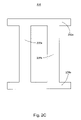
- FIG. 2C depicts a side view of the dielectric material 204 .
- the dielectric material 204 may include header portions 205 a , 205 b , that extend substantially parallel to one another.
- the dielectric material may further include interconnecting portions 206 a , 206 b that extend substantially parallel to one another and substantially perpendicular to the header portions 205 a , 205 b .
- the interconnecting portions 206 a , 206 b may connect the header portion 205 a to the header portion 205 b.
- the dielectric material 204 may be disposed between adjacent leadframe assemblies 126 having signal contacts S (i.e., the inner leadframe assemblies 126 shown in FIGS. 2A and 2B ). More specifically, the header portion 205 a of the dielectric material 204 may be adjacent to the first leadframe housing 128 and may extend along a length thereof. The header portion 205 b of the dielectric material 204 may be adjacent to the second leadframe housing 130 and may extend along a length thereof. Thus, the header portions 205 a , 205 b may be disposed adjacent to at least a portion of each electrical contact 114 in the inner leadframe assemblies 126 .
- the interconnecting portions 206 a , 206 b of the dielectric material 204 may extend substantially parallel to the electrical contacts 114 in the inner leadframe assemblies 126 .
- the interconnecting portions 206 a , 206 b may extend along the lengths of each signal contact housed in the inner leadframe assemblies 126 .
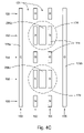
- FIG. 2D depicts a contact arrangement 290 , viewed from the face of the plug connector 202 , that includes the linear arrays of electrical contacts 114 and a portion of the dielectric material 204 .
- the electrical contacts 114 may be arranged in a 5 ⁇ 4 array and may define contact rows 150 , 152 , 154 , 156 , 158 and contact columns 160 , 162 , 164 , 166 .
- the electrical contacts 114 in the plug connector 202 may have a cross-section that defines two opposing edges and two opposing broadsides.
- the electrical contacts 114 may be arranged edge-to-edge along each of the columns 160 , 162 , 164 , 166 .
- the electrical contacts 114 may be arranged broadside-to-broadside along each of the rows 150 , 152 , 154 , 156 , 158 .
- the broadsides of the electrical contacts 114 in the rows 150 , 154 , 158 may be smaller than the broadsides of the electrical contacts 114 in the rows 152 , 156 .
- the interconnecting portions 206 a , 206 b of the dielectric material 204 may define a generally rectangular cross-section and may be positioned between adjacent signal contacts S in the columns 162 , 164 . That is, the interconnecting portions 206 a , 206 b may be positioned between the signal contacts S of each broadside-coupled differential signal pair 174 in the plug connector 202 .
- each of the electrical contacts 114 may be surrounded on all sides by the dielectric 176 , which may be different than the dielectric material 204 disposed between the broadside-coupled differential signal pairs 174 .
- the interconnecting portions 206 a , 206 b may extend a greater distance than each of the electrical contacts 114 in the direction of the rows 150 , 152 , 154 , 156 , 158 (i.e., the interconnecting portions 206 a , 206 b may be wider than the electrical contacts 114 ), though it will be appreciated that the widths of the interconnecting portions 206 a , 206 b may be equal to or less than the widths of the electrical contacts 114 in other embodiments.
- the commoned ground plate 178 may also include mating interfaces 184 extending from the plate portion 180 , and extending above the first leadframe housing 128 of the lead frame assembly 126 .
- the mating interfaces 184 may be blade-shaped, and may be received by the respective mating ends 141 of the electrical contacts 136 .
- An object of the dielectric material 204 is to change the impedance slightly between signal and ground to minimize the coupling wave and the insertion loss suck out associated therewith.
- the ground plane is to minimize the signal pair coupling to the ground individual pin edge and to provide a continuous ground plane.
Abstract
Description
Claims (23)
Priority Applications (7)
| Application Number | Priority Date | Filing Date | Title |
|---|---|---|---|
| US11/866,061 US7713088B2 (en) | 2006-10-05 | 2007-10-02 | Broadside-coupled signal pair configurations for electrical connectors |
| PCT/US2007/021282 WO2008045269A2 (en) | 2006-10-05 | 2007-10-03 | Broadside-coupled signal pair configurations for electrical connectors |
| CN2007800370806A CN101523669B (en) | 2006-10-05 | 2007-10-03 | Broadside-coupled signal pair configurations for electrical connectors |
| EP07839815.3A EP2084785B1 (en) | 2006-10-30 | 2007-10-26 | Broadside-coupled signal pair configurations for electrical connectors |
| CN2010105261048A CN102064406B (en) | 2006-10-30 | 2007-10-26 | Broadside-coupled signal pair configurations for electrical connectors |
| PCT/US2007/022753 WO2008054683A1 (en) | 2006-10-30 | 2007-10-26 | Broadside-coupled signal pair configurations for electrical connectors |
| CN2007800406013A CN101536259B (en) | 2006-10-30 | 2007-10-26 | Electrical connectors |
Applications Claiming Priority (2)
| Application Number | Priority Date | Filing Date | Title |
|---|---|---|---|
| US84953506P | 2006-10-05 | 2006-10-05 | |
| US11/866,061 US7713088B2 (en) | 2006-10-05 | 2007-10-02 | Broadside-coupled signal pair configurations for electrical connectors |
Publications (2)
| Publication Number | Publication Date |
|---|---|
| US20080085618A1 US20080085618A1 (en) | 2008-04-10 |
| US7713088B2 true US7713088B2 (en) | 2010-05-11 |
Family
ID=39275288
Family Applications (1)
| Application Number | Title | Priority Date | Filing Date |
|---|---|---|---|
| US11/866,061 Active US7713088B2 (en) | 2006-10-05 | 2007-10-02 | Broadside-coupled signal pair configurations for electrical connectors |
Country Status (2)
| Country | Link |
|---|---|
| US (1) | US7713088B2 (en) |
| WO (1) | WO2008045269A2 (en) |
Cited By (8)
| Publication number | Priority date | Publication date | Assignee | Title |
|---|---|---|---|---|
| US20110021083A1 (en) * | 2009-07-24 | 2011-01-27 | Fci Americas Technology, Inc. | Dual Impedance Electrical Connector |
| US20110159744A1 (en) * | 2009-12-30 | 2011-06-30 | Buck Jonathan E | Electrical connector having impedance tuning ribs |
| US20120135615A1 (en) * | 2010-11-30 | 2012-05-31 | Fujitsu Component Limited | Electronic connector |
| US20120178273A1 (en) * | 2011-01-06 | 2012-07-12 | International Business Machines Corporation | Tall mezzanine connector |
| US20120178292A1 (en) * | 2011-01-06 | 2012-07-12 | Fujitsu Component Limited | Connector |
| US20130017732A1 (en) * | 2011-01-15 | 2013-01-17 | Parke Eugene James | Method and apparatus for detecting improper connector seating or engagement |
| US20140111960A1 (en) * | 2012-10-23 | 2014-04-24 | Tyco Electronics Corporation | Leadframe module for an electrical connector |
| US9136634B2 (en) | 2010-09-03 | 2015-09-15 | Fci Americas Technology Llc | Low-cross-talk electrical connector |
Families Citing this family (13)
| Publication number | Priority date | Publication date | Assignee | Title |
|---|---|---|---|---|
| US7524209B2 (en) * | 2003-09-26 | 2009-04-28 | Fci Americas Technology, Inc. | Impedance mating interface for electrical connectors |
| US7708569B2 (en) | 2006-10-30 | 2010-05-04 | Fci Americas Technology, Inc. | Broadside-coupled signal pair configurations for electrical connectors |
| US9165615B2 (en) | 2010-03-24 | 2015-10-20 | Rambus Inc. | Coded differential intersymbol interference reduction |
| DE102010061849A1 (en) * | 2010-11-24 | 2012-05-24 | Robert Bosch Gmbh | Magnetic shielding for bus systems |
| CN104183959B (en) * | 2013-05-28 | 2017-09-22 | 中航光电科技股份有限公司 | Electric connector with high differential characteristic impedance |
| CN106104933B (en) | 2014-01-22 | 2020-09-11 | 安费诺有限公司 | High speed, high density electrical connector with shielded signal paths |
| JP6401968B2 (en) * | 2014-08-19 | 2018-10-10 | ホシデン株式会社 | Connector and connector manufacturing method |
| US9730313B2 (en) | 2014-11-21 | 2017-08-08 | Amphenol Corporation | Mating backplane for high speed, high density electrical connector |
| TWI712222B (en) | 2015-07-23 | 2020-12-01 | 美商安芬諾Tcs公司 | Connector, method of manufacturing connector, extender module for connector, and electric system |
| CN108631094B (en) * | 2017-03-16 | 2020-02-04 | 莫列斯有限公司 | Electric connector and electric connector combination |
| CN109599689B (en) * | 2017-09-30 | 2020-11-17 | 中航光电科技股份有限公司 | Connector assembly |
| JP6711936B2 (en) * | 2019-03-06 | 2020-06-17 | 株式会社オートネットワーク技術研究所 | Connector structure |
| EP3973597A4 (en) | 2019-05-20 | 2023-06-28 | Amphenol Corporation | High density, high speed electrical connector |
Citations (175)
| Publication number | Priority date | Publication date | Assignee | Title |
|---|---|---|---|---|
| US3286220A (en) | 1964-06-10 | 1966-11-15 | Amp Inc | Electrical connector means |
| US3390369A (en) | 1966-01-05 | 1968-06-25 | Killark Electric Mfg Company | Electric plug or receptacle assembly with interchangeable parts |
| US3538486A (en) | 1967-05-25 | 1970-11-03 | Amp Inc | Connector device with clamping contact means |
| US3587028A (en) | 1969-04-28 | 1971-06-22 | Ibm | Coaxial connector guide and grounding structure |
| US3669054A (en) | 1970-03-23 | 1972-06-13 | Amp Inc | Method of manufacturing electrical terminals |
| US3748633A (en) | 1972-01-24 | 1973-07-24 | Amp Inc | Square post connector |
| US4045105A (en) | 1974-09-23 | 1977-08-30 | Advanced Memory Systems, Inc. | Interconnected leadless package receptacle |
| US4076362A (en) | 1976-02-20 | 1978-02-28 | Japan Aviation Electronics Industry Ltd. | Contact driver |
| US4159861A (en) | 1977-12-30 | 1979-07-03 | International Telephone And Telegraph Corporation | Zero insertion force connector |
| US4260212A (en) | 1979-03-20 | 1981-04-07 | Amp Incorporated | Method of producing insulated terminals |
| US4288139A (en) | 1979-03-06 | 1981-09-08 | Amp Incorporated | Trifurcated card edge terminal |
| US4383724A (en) | 1980-06-03 | 1983-05-17 | E. I. Du Pont De Nemours And Company | Bridge connector for electrically connecting two pins |
| US4402563A (en) | 1981-05-26 | 1983-09-06 | Aries Electronics, Inc. | Zero insertion force connector |
| US4482937A (en) | 1982-09-30 | 1984-11-13 | Control Data Corporation | Board to board interconnect structure |
| US4560222A (en) | 1984-05-17 | 1985-12-24 | Molex Incorporated | Drawer connector |
| US4717360A (en) | 1986-03-17 | 1988-01-05 | Zenith Electronics Corporation | Modular electrical connector |
| US4734060A (en) | 1986-01-31 | 1988-03-29 | Kel Corporation | Connector device |
| EP0273683A2 (en) | 1986-12-26 | 1988-07-06 | Fujitsu Limited | An electrical connector |
| US4776803A (en) | 1986-11-26 | 1988-10-11 | Minnesota Mining And Manufacturing Company | Integrally molded card edge cable termination assembly, contact, machine and method |
| US4867713A (en) | 1987-02-24 | 1989-09-19 | Kabushiki Kaisha Toshiba | Electrical connector |
| US4907990A (en) | 1988-10-07 | 1990-03-13 | Molex Incorporated | Elastically supported dual cantilever beam pin-receiving electrical contact |
| US4913664A (en) | 1988-11-25 | 1990-04-03 | Molex Incorporated | Miniature circular DIN connector |
| US4973271A (en) | 1989-01-30 | 1990-11-27 | Yazaki Corporation | Low insertion-force terminal |
| US5066236A (en) | 1989-10-10 | 1991-11-19 | Amp Incorporated | Impedance matched backplane connector |
| US5077893A (en) | 1989-09-26 | 1992-01-07 | Molex Incorporated | Method for forming electrical terminal |
| US5098311A (en) | 1989-06-12 | 1992-03-24 | Ohio Associated Enterprises, Inc. | Hermaphroditic interconnect system |
| US5163849A (en) | 1991-08-27 | 1992-11-17 | Amp Incorporated | Lead frame and electrical connector |
| US5167528A (en) | 1990-04-20 | 1992-12-01 | Matsushita Electric Works, Ltd. | Method of manufacturing an electrical connector |
| US5174770A (en) | 1990-11-15 | 1992-12-29 | Amp Incorporated | Multicontact connector for signal transmission |
| US5192231A (en) | 1990-06-19 | 1993-03-09 | Echelon Corporation | Power line communications coupler |
| US5224867A (en) | 1990-10-08 | 1993-07-06 | Daiichi Denshi Kogyo Kabushiki Kaisha | Electrical connector for coaxial flat cable |
| US5238414A (en) | 1991-07-24 | 1993-08-24 | Hirose Electric Co., Ltd. | High-speed transmission electrical connector |
| US5254012A (en) | 1992-08-21 | 1993-10-19 | Industrial Technology Research Institute | Zero insertion force socket |
| US5274918A (en) | 1993-04-15 | 1994-01-04 | The Whitaker Corporation | Method for producing contact shorting bar insert for modular jack assembly |
| US5277624A (en) | 1991-12-23 | 1994-01-11 | Souriau Et Cie | Modular electrical-connection element |
| US5286212A (en) | 1992-03-09 | 1994-02-15 | The Whitaker Corporation | Shielded back plane connector |
| US5302135A (en) | 1993-02-09 | 1994-04-12 | Lee Feng Jui | Electrical plug |
| US5342211A (en) | 1992-03-09 | 1994-08-30 | The Whitaker Corporation | Shielded back plane connector |
| US5356301A (en) | 1991-12-23 | 1994-10-18 | Framatome Connectors International | Modular electrical-connection element |
| US5356300A (en) | 1993-09-16 | 1994-10-18 | The Whitaker Corporation | Blind mating guides with ground contacts |
| US5357050A (en) | 1992-11-20 | 1994-10-18 | Ast Research, Inc. | Apparatus and method to reduce electromagnetic emissions in a multi-layer circuit board |
| US5431578A (en) | 1994-03-02 | 1995-07-11 | Abrams Electronics, Inc. | Compression mating electrical connector |
| US5475922A (en) | 1992-12-18 | 1995-12-19 | Fujitsu Ltd. | Method of assembling a connector using frangible contact parts |
| US5525067A (en) | 1994-02-03 | 1996-06-11 | Motorola, Inc | Ground plane interconnection system using multiple connector contacts |
| US5558542A (en) | 1995-09-08 | 1996-09-24 | Molex Incorporated | Electrical connector with improved terminal-receiving passage means |
| US5586914A (en) | 1995-05-19 | 1996-12-24 | The Whitaker Corporation | Electrical connector and an associated method for compensating for crosstalk between a plurality of conductors |
| US5590463A (en) | 1995-07-18 | 1997-01-07 | Elco Corporation | Circuit board connectors |
| US5609502A (en) | 1995-03-31 | 1997-03-11 | The Whitaker Corporation | Contact retention system |
| US5713746A (en) | 1994-02-08 | 1998-02-03 | Berg Technology, Inc. | Electrical connector |
| US5730609A (en) | 1995-04-28 | 1998-03-24 | Molex Incorporated | High performance card edge connector |
| US5741161A (en) | 1996-01-04 | 1998-04-21 | Pcd Inc. | Electrical connection system with discrete wire interconnections |
| US5741144A (en) | 1995-06-12 | 1998-04-21 | Berg Technology, Inc. | Low cross and impedance controlled electric connector |
| US5795191A (en) | 1996-09-11 | 1998-08-18 | Preputnick; George | Connector assembly with shielded modules and method of making same |
| US5817973A (en) | 1995-06-12 | 1998-10-06 | Berg Technology, Inc. | Low cross talk and impedance controlled electrical cable assembly |
| US5853797A (en) | 1995-11-20 | 1998-12-29 | Lucent Technologies, Inc. | Method of providing corrosion protection |
| US5908333A (en) | 1997-07-21 | 1999-06-01 | Rambus, Inc. | Connector with integral transmission line bus |
| US5925274A (en) | 1996-07-11 | 1999-07-20 | Mckinney; Duane M. | Electrical range power override timer unit |
| US5961355A (en) * | 1997-12-17 | 1999-10-05 | Berg Technology, Inc. | High density interstitial connector system |
| US5967844A (en) | 1995-04-04 | 1999-10-19 | Berg Technology, Inc. | Electrically enhanced modular connector for printed wiring board |
| US5971817A (en) | 1995-09-27 | 1999-10-26 | Siemens Aktiengesellschaft | Contact spring for a plug-in connector |
| US5980321A (en) | 1997-02-07 | 1999-11-09 | Teradyne, Inc. | High speed, high density electrical connector |
| US5993259A (en) | 1997-02-07 | 1999-11-30 | Teradyne, Inc. | High speed, high density electrical connector |
| JP2000003743A (en) | 1998-06-15 | 2000-01-07 | Honda Tsushin Kogyo Co Ltd | Connector for printed board |
| JP2000003746A (en) | 1998-06-15 | 2000-01-07 | Honda Tsushin Kogyo Co Ltd | Connector for printed circuit board |
| JP2000003745A (en) | 1998-06-15 | 2000-01-07 | Honda Tsushin Kogyo Co Ltd | Connector for printed circuit board |
| JP2000003744A (en) | 1998-06-15 | 2000-01-07 | Honda Tsushin Kogyo Co Ltd | Connector for printed circuit board |
| US6042389A (en) | 1996-10-10 | 2000-03-28 | Berg Technology, Inc. | Low profile connector |
| US6050862A (en) | 1997-05-20 | 2000-04-18 | Yazaki Corporation | Female terminal with flexible contact area having inclined free edge portion |
| US6068520A (en) | 1997-03-13 | 2000-05-30 | Berg Technology, Inc. | Low profile double deck connector with improved cross talk isolation |
| US6099332A (en) | 1998-05-26 | 2000-08-08 | The Whitaker Corp. | Connector with adaptable insert |
| US6116926A (en) | 1999-04-21 | 2000-09-12 | Berg Technology, Inc. | Connector for electrical isolation in a condensed area |
| US6116965A (en) | 1998-02-27 | 2000-09-12 | Lucent Technologies Inc. | Low crosstalk connector configuration |
| US6123554A (en) | 1999-05-28 | 2000-09-26 | Berg Technology, Inc. | Connector cover with board stiffener |
| US6125535A (en) | 1998-12-31 | 2000-10-03 | Hon Hai Precision Ind. Co., Ltd. | Method for insert molding a contact module |
| US6129592A (en) | 1997-11-04 | 2000-10-10 | The Whitaker Corporation | Connector assembly having terminal modules |
| US6139336A (en) | 1996-11-14 | 2000-10-31 | Berg Technology, Inc. | High density connector having a ball type of contact surface |
| US6146157A (en) | 1997-07-08 | 2000-11-14 | Framatome Connectors International | Connector assembly for printed circuit boards |
| US6150729A (en) | 1999-07-01 | 2000-11-21 | Lsi Logic Corporation | Routing density enhancement for semiconductor BGA packages and printed wiring boards |
| US6171149B1 (en) | 1998-12-28 | 2001-01-09 | Berg Technology, Inc. | High speed connector and method of making same |
| US6171115B1 (en) | 2000-02-03 | 2001-01-09 | Tyco Electronics Corporation | Electrical connector having circuit boards and keying for different types of circuit boards |
| US6190213B1 (en) | 1998-01-07 | 2001-02-20 | Amphenol-Tuchel Electronics Gmbh | Contact element support in particular for a thin smart card connector |
| US6212755B1 (en) | 1997-09-19 | 2001-04-10 | Murata Manufacturing Co., Ltd. | Method for manufacturing insert-resin-molded product |
| US6219913B1 (en) | 1997-01-13 | 2001-04-24 | Sumitomo Wiring Systems, Ltd. | Connector producing method and a connector produced by insert molding |
| US6220896B1 (en) | 1999-05-13 | 2001-04-24 | Berg Technology, Inc. | Shielded header |
| WO2001029931A1 (en) | 1999-10-18 | 2001-04-26 | Erni Elektroapparate Gmbh | Shielded plug-in connector |
| US6227882B1 (en) | 1997-10-01 | 2001-05-08 | Berg Technology, Inc. | Connector for electrical isolation in a condensed area |
| WO2001039332A1 (en) | 1999-11-24 | 2001-05-31 | Teradyne, Inc. | Differential signal electrical connectors |
| US6267604B1 (en) | 2000-02-03 | 2001-07-31 | Tyco Electronics Corporation | Electrical connector including a housing that holds parallel circuit boards |
| US6269539B1 (en) | 1996-06-25 | 2001-08-07 | Fujitsu Takamisawa Component Limited | Fabrication method of connector having internal switch |
| US6280209B1 (en) | 1999-07-16 | 2001-08-28 | Molex Incorporated | Connector with improved performance characteristics |
| US6293827B1 (en) | 2000-02-03 | 2001-09-25 | Teradyne, Inc. | Differential signal electrical connector |
| US6319075B1 (en) | 1998-04-17 | 2001-11-20 | Fci Americas Technology, Inc. | Power connector |
| US6328602B1 (en) | 1999-06-17 | 2001-12-11 | Nec Corporation | Connector with less crosstalk |
| US6343955B2 (en) | 2000-03-29 | 2002-02-05 | Berg Technology, Inc. | Electrical connector with grounding system |
| US6347952B1 (en) | 1999-10-01 | 2002-02-19 | Sumitomo Wiring Systems, Ltd. | Connector with locking member and audible indication of complete locking |
| US6350134B1 (en) | 2000-07-25 | 2002-02-26 | Tyco Electronics Corporation | Electrical connector having triad contact groups arranged in an alternating inverted sequence |
| US6354877B1 (en) | 1996-08-20 | 2002-03-12 | Fci Americas Technology, Inc. | High speed modular electrical connector and receptacle for use therein |
| US6358061B1 (en) | 1999-11-09 | 2002-03-19 | Molex Incorporated | High-speed connector with shorting capability |
| US6361366B1 (en) | 1997-08-20 | 2002-03-26 | Fci Americas Technology, Inc. | High speed modular electrical connector and receptacle for use therein |
| US6363607B1 (en) | 1998-12-24 | 2002-04-02 | Hon Hai Precision Ind. Co., Ltd. | Method for manufacturing a high density connector |
| US6368121B1 (en) * | 1998-08-24 | 2002-04-09 | Fujitsu Takamisawa Component Limited | Plug connector, jack connector and connector assembly |
| US6371773B1 (en) | 2000-03-23 | 2002-04-16 | Ohio Associated Enterprises, Inc. | High density interconnect system and method |
| US6375478B1 (en) | 1999-06-18 | 2002-04-23 | Nec Corporation | Connector well fit with printed circuit board |
| US6386914B1 (en) | 2001-03-26 | 2002-05-14 | Amphenol Corporation | Electrical connector having mixed grounded and non-grounded contacts |
| US6409543B1 (en) | 2001-01-25 | 2002-06-25 | Teradyne, Inc. | Connector molding method and shielded waferized connector made therefrom |
| US20020098727A1 (en) | 1998-11-24 | 2002-07-25 | Teradyne, Inc. | Electrical connector |
| US20020106930A1 (en) | 2001-02-05 | 2002-08-08 | Harting Kgaa | Contact assembly for a plug connector, in particular for a PCB plug connector |
| US6431914B1 (en) | 2001-06-04 | 2002-08-13 | Hon Hai Precision Ind. Co., Ltd. | Grounding scheme for a high speed backplane connector system |
| US6435914B1 (en) | 2001-06-27 | 2002-08-20 | Hon Hai Precision Ind. Co., Ltd. | Electrical connector having improved shielding means |
| US6435913B1 (en) | 2001-06-15 | 2002-08-20 | Hon Hai Precision Ind. Co., Ltd. | Header connector having two shields therein |
| US6461202B2 (en) | 2001-01-30 | 2002-10-08 | Tyco Electronics Corporation | Terminal module having open side for enhanced electrical performance |
| US6482038B2 (en) | 2001-02-23 | 2002-11-19 | Fci Americas Technology, Inc. | Header assembly for mounting to a circuit substrate |
| US6485330B1 (en) | 1998-05-15 | 2002-11-26 | Fci Americas Technology, Inc. | Shroud retention wafer |
| US6494734B1 (en) | 1997-09-30 | 2002-12-17 | Fci Americas Technology, Inc. | High density electrical connector assembly |
| US6503103B1 (en) | 1997-02-07 | 2003-01-07 | Teradyne, Inc. | Differential signal electrical connectors |
| US6506081B2 (en) | 2001-05-31 | 2003-01-14 | Tyco Electronics Corporation | Floatable connector assembly with a staggered overlapping contact pattern |
| US6520803B1 (en) | 2002-01-22 | 2003-02-18 | Fci Americas Technology, Inc. | Connection of shields in an electrical connector |
| US6527587B1 (en) | 1999-04-29 | 2003-03-04 | Fci Americas Technology, Inc. | Header assembly for mounting to a circuit substrate and having ground shields therewithin |
| US6537111B2 (en) | 2000-05-31 | 2003-03-25 | Wabco Gmbh And Co. Ohg | Electric contact plug with deformable attributes |
| US6540559B1 (en) | 2001-09-28 | 2003-04-01 | Tyco Electronics Corporation | Connector with staggered contact pattern |
| US6547066B2 (en) | 2001-08-31 | 2003-04-15 | Labelwhiz.Com, Inc. | Compact disk storage systems |
| US6547606B1 (en) | 2001-10-10 | 2003-04-15 | Methode Development Company | Termination assembly formed by diverse angularly disposed conductors and termination method |
| US6572410B1 (en) | 2002-02-20 | 2003-06-03 | Fci Americas Technology, Inc. | Connection header and shield |
| US20030143894A1 (en) | 2002-01-28 | 2003-07-31 | Kline Richard S. | Connector assembly interface for L-shaped ground shields and differential contact pairs |
| US6609933B2 (en) | 2001-07-04 | 2003-08-26 | Nec Tokin Iwate, Ltd. | Shield connector |
| US20030171010A1 (en) | 2001-11-14 | 2003-09-11 | Winings Clifford L. | Cross talk reduction and impedance-matching for high speed electrical connectors |
| US20030203665A1 (en) | 2002-04-26 | 2003-10-30 | Koji Ohnishi | High-frequency electric connector having no ground terminals |
| US6641411B1 (en) | 2002-07-24 | 2003-11-04 | Maxxan Systems, Inc. | Low cost high speed connector |
| US6652318B1 (en) | 2002-05-24 | 2003-11-25 | Fci Americas Technology, Inc. | Cross-talk canceling technique for high speed electrical connectors |
| US6652319B1 (en) | 2002-05-22 | 2003-11-25 | Hon Hai Precision Ind. Co., Ltd. | High speed connector with matched impedance |
| US20030220021A1 (en) | 2002-05-22 | 2003-11-27 | Whiteman Robert Neil | High speed electrical connector |
| US6672907B2 (en) | 2000-05-02 | 2004-01-06 | Fci Americas Technology, Inc. | Connector |
| US6692272B2 (en) | 2001-11-14 | 2004-02-17 | Fci Americas Technology, Inc. | High speed electrical connector |
| US6695627B2 (en) | 2001-08-02 | 2004-02-24 | Fci Americas Technnology, Inc. | Profiled header ground pin |
| US6700455B2 (en) | 2001-08-23 | 2004-03-02 | Intel Corporation | Electromagnetic emission reduction technique for shielded connectors |
| US6717825B2 (en) | 2002-01-18 | 2004-04-06 | Fci Americas Technology, Inc. | Electrical connection system for two printed circuit boards mounted on opposite sides of a mid-plane printed circuit board at angles to each other |
| US6762067B1 (en) | 2000-01-18 | 2004-07-13 | Fairchild Semiconductor Corporation | Method of packaging a plurality of devices utilizing a plurality of lead frames coupled together by rails |
| US6764341B2 (en) | 2001-05-25 | 2004-07-20 | Erni Elektroapparate Gmbh | Plug connector that can be turned by 90° |
| US6805278B1 (en) | 1999-10-19 | 2004-10-19 | Fci America Technology, Inc. | Self-centering connector with hold down |
| US6808399B2 (en) | 2002-12-02 | 2004-10-26 | Tyco Electronics Corporation | Electrical connector with wafers having split ground planes |
| US6824391B2 (en) | 2000-02-03 | 2004-11-30 | Tyco Electronics Corporation | Electrical connector having customizable circuit board wafers |
| US20050009402A1 (en) | 2003-07-11 | 2005-01-13 | Chih-Ming Chien | Electrical connector with double mating interfaces for electronic components |
| US20050020109A1 (en) | 2001-11-14 | 2005-01-27 | Alan Raistrick | Impedance control in electrical connectors |
| US6848944B2 (en) | 2001-11-12 | 2005-02-01 | Fci Americas Technology, Inc. | Connector for high-speed communications |
| US6852567B1 (en) | 1999-05-31 | 2005-02-08 | Infineon Technologies A.G. | Method of assembling a semiconductor device package |
| US6863543B2 (en) | 2002-05-06 | 2005-03-08 | Molex Incorporated | Board-to-board connector with compliant mounting pins |
| US6869292B2 (en) | 2001-07-31 | 2005-03-22 | Fci Americas Technology, Inc. | Modular mezzanine connector |
| EP1148587B1 (en) | 1996-07-17 | 2005-04-13 | Minnesota Mining And Manufacturing Company | Electrical interconnection system and device |
| US6890214B2 (en) | 2002-08-21 | 2005-05-10 | Tyco Electronics Corporation | Multi-sequenced contacts from single lead frame |
| US6905368B2 (en) * | 2002-11-13 | 2005-06-14 | Ddk Ltd. | Connector for use with high frequency signals |
| US20050170700A1 (en) | 2001-11-14 | 2005-08-04 | Shuey Joseph B. | High speed electrical connector without ground contacts |
| US6932649B1 (en) | 2004-03-19 | 2005-08-23 | Tyco Electronics Corporation | Active wafer for improved gigabit signal recovery, in a serial point-to-point architecture |
| US6945796B2 (en) | 1999-07-16 | 2005-09-20 | Molex Incorporated | Impedance-tuned connector |
| US6953351B2 (en) | 2002-06-21 | 2005-10-11 | Molex Incorporated | High-density, impedance-tuned connector having modular construction |
| US6969268B2 (en) | 2002-06-11 | 2005-11-29 | Molex Incorporated | Impedance-tuned terminal contact arrangement and connectors incorporating same |
| US20050277221A1 (en) | 2004-06-10 | 2005-12-15 | Samtec, Inc. | Array connector having improved electrical characteristics and increased signal pins with decreased ground pins |
| US6979226B2 (en) | 2003-07-10 | 2005-12-27 | J.S.T. Mfg. Co., Ltd. | Connector |
| US20060014433A1 (en) | 2004-07-14 | 2006-01-19 | Consoli John J | Electrical connector with ESD protection |
| US6994569B2 (en) | 2001-11-14 | 2006-02-07 | Fci America Technology, Inc. | Electrical connectors having contacts that may be selectively designated as either signal or ground contacts |
| US20060046526A1 (en) | 2004-08-31 | 2006-03-02 | Minich Steven E | Contact protector for electrical connectors |
| US7057115B2 (en) | 2004-01-26 | 2006-06-06 | Litton Systems, Inc. | Multilayered circuit board for high-speed, differential signals |
| US20060121749A1 (en) | 2004-12-02 | 2006-06-08 | Tyco Electronics Corporation | Noise canceling differential connector and footprint |
| US7097506B2 (en) | 2002-10-15 | 2006-08-29 | Japan Aviation Electronics Industry Limited | Contact module in which mounting of contacts is simplified |
| US20060192274A1 (en) | 2004-11-12 | 2006-08-31 | Chippac, Inc | Semiconductor package having double layer leadframe |
| US7131870B2 (en) | 2005-02-07 | 2006-11-07 | Tyco Electronics Corporation | Electrical connector |
| US7157250B2 (en) | 2001-10-23 | 2007-01-02 | Ajinomoto Co., Inc. | Glutamic acid receptor and utilization thereof |
| US20070099455A1 (en) | 2005-11-02 | 2007-05-03 | Tyco Electronic Corporation | Orthogonal connector |
| US20070205774A1 (en) | 2006-03-03 | 2007-09-06 | Fci Americas Technology, Inc.. | Electrical connectors |
| US20070207641A1 (en) | 2006-03-03 | 2007-09-06 | Fci Americas Technology, Inc. | High-density orthogonal connector |
| US7320621B2 (en) | 2005-03-31 | 2008-01-22 | Molex Incorporated | High-density, robust connector with castellations |
| US20080102702A1 (en) | 2006-10-30 | 2008-05-01 | Stefaan Hendrik Jozef Sercu | Broadside-Coupled Signal Pair Configurations For Electrical Connectors |
| US7407413B2 (en) | 2006-03-03 | 2008-08-05 | Fci Americas Technology, Inc. | Broadside-to-edge-coupling connector system |
| US7422484B2 (en) | 2004-07-01 | 2008-09-09 | Amphenol Corporation | Midplane especially applicable to an orthogonal architecture electronic system |
| US20090011641A1 (en) | 2005-06-30 | 2009-01-08 | Amphenol Corporation | High speed, high density electrical connector |
| US7524209B2 (en) | 2003-09-26 | 2009-04-28 | Fci Americas Technology, Inc. | Impedance mating interface for electrical connectors |
Family Cites Families (1)
| Publication number | Priority date | Publication date | Assignee | Title |
|---|---|---|---|---|
| EP1461548A4 (en) * | 2001-04-18 | 2007-03-14 | Bal Seal Engineering Co | Self contained anti-blowout seal for fluids or gases |
-
2007
- 2007-10-02 US US11/866,061 patent/US7713088B2/en active Active
- 2007-10-03 WO PCT/US2007/021282 patent/WO2008045269A2/en active Application Filing
Patent Citations (200)
| Publication number | Priority date | Publication date | Assignee | Title |
|---|---|---|---|---|
| US3286220A (en) | 1964-06-10 | 1966-11-15 | Amp Inc | Electrical connector means |
| US3390369A (en) | 1966-01-05 | 1968-06-25 | Killark Electric Mfg Company | Electric plug or receptacle assembly with interchangeable parts |
| US3538486A (en) | 1967-05-25 | 1970-11-03 | Amp Inc | Connector device with clamping contact means |
| US3587028A (en) | 1969-04-28 | 1971-06-22 | Ibm | Coaxial connector guide and grounding structure |
| US3669054A (en) | 1970-03-23 | 1972-06-13 | Amp Inc | Method of manufacturing electrical terminals |
| US3748633A (en) | 1972-01-24 | 1973-07-24 | Amp Inc | Square post connector |
| US4045105A (en) | 1974-09-23 | 1977-08-30 | Advanced Memory Systems, Inc. | Interconnected leadless package receptacle |
| US4076362A (en) | 1976-02-20 | 1978-02-28 | Japan Aviation Electronics Industry Ltd. | Contact driver |
| US4159861A (en) | 1977-12-30 | 1979-07-03 | International Telephone And Telegraph Corporation | Zero insertion force connector |
| US4288139A (en) | 1979-03-06 | 1981-09-08 | Amp Incorporated | Trifurcated card edge terminal |
| US4260212A (en) | 1979-03-20 | 1981-04-07 | Amp Incorporated | Method of producing insulated terminals |
| US4383724A (en) | 1980-06-03 | 1983-05-17 | E. I. Du Pont De Nemours And Company | Bridge connector for electrically connecting two pins |
| US4402563A (en) | 1981-05-26 | 1983-09-06 | Aries Electronics, Inc. | Zero insertion force connector |
| US4482937A (en) | 1982-09-30 | 1984-11-13 | Control Data Corporation | Board to board interconnect structure |
| US4560222A (en) | 1984-05-17 | 1985-12-24 | Molex Incorporated | Drawer connector |
| US4734060A (en) | 1986-01-31 | 1988-03-29 | Kel Corporation | Connector device |
| US4717360A (en) | 1986-03-17 | 1988-01-05 | Zenith Electronics Corporation | Modular electrical connector |
| US4776803A (en) | 1986-11-26 | 1988-10-11 | Minnesota Mining And Manufacturing Company | Integrally molded card edge cable termination assembly, contact, machine and method |
| EP0273683A2 (en) | 1986-12-26 | 1988-07-06 | Fujitsu Limited | An electrical connector |
| US4815987A (en) | 1986-12-26 | 1989-03-28 | Fujitsu Limited | Electrical connector |
| US4867713A (en) | 1987-02-24 | 1989-09-19 | Kabushiki Kaisha Toshiba | Electrical connector |
| US4907990A (en) | 1988-10-07 | 1990-03-13 | Molex Incorporated | Elastically supported dual cantilever beam pin-receiving electrical contact |
| US4913664A (en) | 1988-11-25 | 1990-04-03 | Molex Incorporated | Miniature circular DIN connector |
| US4973271A (en) | 1989-01-30 | 1990-11-27 | Yazaki Corporation | Low insertion-force terminal |
| US5098311A (en) | 1989-06-12 | 1992-03-24 | Ohio Associated Enterprises, Inc. | Hermaphroditic interconnect system |
| US5077893A (en) | 1989-09-26 | 1992-01-07 | Molex Incorporated | Method for forming electrical terminal |
| US5066236A (en) | 1989-10-10 | 1991-11-19 | Amp Incorporated | Impedance matched backplane connector |
| US5167528A (en) | 1990-04-20 | 1992-12-01 | Matsushita Electric Works, Ltd. | Method of manufacturing an electrical connector |
| US5192231A (en) | 1990-06-19 | 1993-03-09 | Echelon Corporation | Power line communications coupler |
| US5224867A (en) | 1990-10-08 | 1993-07-06 | Daiichi Denshi Kogyo Kabushiki Kaisha | Electrical connector for coaxial flat cable |
| US5174770A (en) | 1990-11-15 | 1992-12-29 | Amp Incorporated | Multicontact connector for signal transmission |
| US5238414A (en) | 1991-07-24 | 1993-08-24 | Hirose Electric Co., Ltd. | High-speed transmission electrical connector |
| US5163849A (en) | 1991-08-27 | 1992-11-17 | Amp Incorporated | Lead frame and electrical connector |
| US5277624A (en) | 1991-12-23 | 1994-01-11 | Souriau Et Cie | Modular electrical-connection element |
| US5356301A (en) | 1991-12-23 | 1994-10-18 | Framatome Connectors International | Modular electrical-connection element |
| US5286212A (en) | 1992-03-09 | 1994-02-15 | The Whitaker Corporation | Shielded back plane connector |
| US5342211A (en) | 1992-03-09 | 1994-08-30 | The Whitaker Corporation | Shielded back plane connector |
| US5254012A (en) | 1992-08-21 | 1993-10-19 | Industrial Technology Research Institute | Zero insertion force socket |
| US5357050A (en) | 1992-11-20 | 1994-10-18 | Ast Research, Inc. | Apparatus and method to reduce electromagnetic emissions in a multi-layer circuit board |
| US5475922A (en) | 1992-12-18 | 1995-12-19 | Fujitsu Ltd. | Method of assembling a connector using frangible contact parts |
| US5302135A (en) | 1993-02-09 | 1994-04-12 | Lee Feng Jui | Electrical plug |
| US5274918A (en) | 1993-04-15 | 1994-01-04 | The Whitaker Corporation | Method for producing contact shorting bar insert for modular jack assembly |
| US5356300A (en) | 1993-09-16 | 1994-10-18 | The Whitaker Corporation | Blind mating guides with ground contacts |
| US5525067A (en) | 1994-02-03 | 1996-06-11 | Motorola, Inc | Ground plane interconnection system using multiple connector contacts |
| US5713746A (en) | 1994-02-08 | 1998-02-03 | Berg Technology, Inc. | Electrical connector |
| US5431578A (en) | 1994-03-02 | 1995-07-11 | Abrams Electronics, Inc. | Compression mating electrical connector |
| US5609502A (en) | 1995-03-31 | 1997-03-11 | The Whitaker Corporation | Contact retention system |
| US6322393B1 (en) | 1995-04-04 | 2001-11-27 | Fci Americas Technology, Inc. | Electrically enhanced modular connector for printed wiring board |
| US5967844A (en) | 1995-04-04 | 1999-10-19 | Berg Technology, Inc. | Electrically enhanced modular connector for printed wiring board |
| US5730609A (en) | 1995-04-28 | 1998-03-24 | Molex Incorporated | High performance card edge connector |
| US5586914A (en) | 1995-05-19 | 1996-12-24 | The Whitaker Corporation | Electrical connector and an associated method for compensating for crosstalk between a plurality of conductors |
| US5741144A (en) | 1995-06-12 | 1998-04-21 | Berg Technology, Inc. | Low cross and impedance controlled electric connector |
| US5817973A (en) | 1995-06-12 | 1998-10-06 | Berg Technology, Inc. | Low cross talk and impedance controlled electrical cable assembly |
| US6146203A (en) | 1995-06-12 | 2000-11-14 | Berg Technology, Inc. | Low cross talk and impedance controlled electrical connector |
| US5590463A (en) | 1995-07-18 | 1997-01-07 | Elco Corporation | Circuit board connectors |
| US5558542A (en) | 1995-09-08 | 1996-09-24 | Molex Incorporated | Electrical connector with improved terminal-receiving passage means |
| US5971817A (en) | 1995-09-27 | 1999-10-26 | Siemens Aktiengesellschaft | Contact spring for a plug-in connector |
| US5853797A (en) | 1995-11-20 | 1998-12-29 | Lucent Technologies, Inc. | Method of providing corrosion protection |
| US5741161A (en) | 1996-01-04 | 1998-04-21 | Pcd Inc. | Electrical connection system with discrete wire interconnections |
| US6269539B1 (en) | 1996-06-25 | 2001-08-07 | Fujitsu Takamisawa Component Limited | Fabrication method of connector having internal switch |
| US5925274A (en) | 1996-07-11 | 1999-07-20 | Mckinney; Duane M. | Electrical range power override timer unit |
| EP1148587B1 (en) | 1996-07-17 | 2005-04-13 | Minnesota Mining And Manufacturing Company | Electrical interconnection system and device |
| US6354877B1 (en) | 1996-08-20 | 2002-03-12 | Fci Americas Technology, Inc. | High speed modular electrical connector and receptacle for use therein |
| US5795191A (en) | 1996-09-11 | 1998-08-18 | Preputnick; George | Connector assembly with shielded modules and method of making same |
| US6042389A (en) | 1996-10-10 | 2000-03-28 | Berg Technology, Inc. | Low profile connector |
| US6139336A (en) | 1996-11-14 | 2000-10-31 | Berg Technology, Inc. | High density connector having a ball type of contact surface |
| US6219913B1 (en) | 1997-01-13 | 2001-04-24 | Sumitomo Wiring Systems, Ltd. | Connector producing method and a connector produced by insert molding |
| US6554647B1 (en) | 1997-02-07 | 2003-04-29 | Teradyne, Inc. | Differential signal electrical connectors |
| US6503103B1 (en) | 1997-02-07 | 2003-01-07 | Teradyne, Inc. | Differential signal electrical connectors |
| US5980321A (en) | 1997-02-07 | 1999-11-09 | Teradyne, Inc. | High speed, high density electrical connector |
| US6379188B1 (en) | 1997-02-07 | 2002-04-30 | Teradyne, Inc. | Differential signal electrical connectors |
| US5993259A (en) | 1997-02-07 | 1999-11-30 | Teradyne, Inc. | High speed, high density electrical connector |
| US6068520A (en) | 1997-03-13 | 2000-05-30 | Berg Technology, Inc. | Low profile double deck connector with improved cross talk isolation |
| US6851974B2 (en) | 1997-05-15 | 2005-02-08 | Fci Americas Technology, Inc. | Shroud retention wafer |
| US6050862A (en) | 1997-05-20 | 2000-04-18 | Yazaki Corporation | Female terminal with flexible contact area having inclined free edge portion |
| EP0891016B1 (en) | 1997-07-08 | 2002-10-09 | Framatome Connectors International | Connector assembly for printed circuit boards |
| US6146157A (en) | 1997-07-08 | 2000-11-14 | Framatome Connectors International | Connector assembly for printed circuit boards |
| US5908333A (en) | 1997-07-21 | 1999-06-01 | Rambus, Inc. | Connector with integral transmission line bus |
| US6361366B1 (en) | 1997-08-20 | 2002-03-26 | Fci Americas Technology, Inc. | High speed modular electrical connector and receptacle for use therein |
| US6212755B1 (en) | 1997-09-19 | 2001-04-10 | Murata Manufacturing Co., Ltd. | Method for manufacturing insert-resin-molded product |
| US6494734B1 (en) | 1997-09-30 | 2002-12-17 | Fci Americas Technology, Inc. | High density electrical connector assembly |
| US6227882B1 (en) | 1997-10-01 | 2001-05-08 | Berg Technology, Inc. | Connector for electrical isolation in a condensed area |
| US6129592A (en) | 1997-11-04 | 2000-10-10 | The Whitaker Corporation | Connector assembly having terminal modules |
| US5961355A (en) * | 1997-12-17 | 1999-10-05 | Berg Technology, Inc. | High density interstitial connector system |
| US6190213B1 (en) | 1998-01-07 | 2001-02-20 | Amphenol-Tuchel Electronics Gmbh | Contact element support in particular for a thin smart card connector |
| US6116965A (en) | 1998-02-27 | 2000-09-12 | Lucent Technologies Inc. | Low crosstalk connector configuration |
| US6319075B1 (en) | 1998-04-17 | 2001-11-20 | Fci Americas Technology, Inc. | Power connector |
| US6485330B1 (en) | 1998-05-15 | 2002-11-26 | Fci Americas Technology, Inc. | Shroud retention wafer |
| US6099332A (en) | 1998-05-26 | 2000-08-08 | The Whitaker Corp. | Connector with adaptable insert |
| JP2000003746A (en) | 1998-06-15 | 2000-01-07 | Honda Tsushin Kogyo Co Ltd | Connector for printed circuit board |
| JP2000003743A (en) | 1998-06-15 | 2000-01-07 | Honda Tsushin Kogyo Co Ltd | Connector for printed board |
| JP2000003745A (en) | 1998-06-15 | 2000-01-07 | Honda Tsushin Kogyo Co Ltd | Connector for printed circuit board |
| JP2000003744A (en) | 1998-06-15 | 2000-01-07 | Honda Tsushin Kogyo Co Ltd | Connector for printed circuit board |
| US6368121B1 (en) * | 1998-08-24 | 2002-04-09 | Fujitsu Takamisawa Component Limited | Plug connector, jack connector and connector assembly |
| US20020098727A1 (en) | 1998-11-24 | 2002-07-25 | Teradyne, Inc. | Electrical connector |
| US6363607B1 (en) | 1998-12-24 | 2002-04-02 | Hon Hai Precision Ind. Co., Ltd. | Method for manufacturing a high density connector |
| US6171149B1 (en) | 1998-12-28 | 2001-01-09 | Berg Technology, Inc. | High speed connector and method of making same |
| US6125535A (en) | 1998-12-31 | 2000-10-03 | Hon Hai Precision Ind. Co., Ltd. | Method for insert molding a contact module |
| US6322379B1 (en) | 1999-04-21 | 2001-11-27 | Fci Americas Technology, Inc. | Connector for electrical isolation in a condensed area |
| US6116926A (en) | 1999-04-21 | 2000-09-12 | Berg Technology, Inc. | Connector for electrical isolation in a condensed area |
| US6527587B1 (en) | 1999-04-29 | 2003-03-04 | Fci Americas Technology, Inc. | Header assembly for mounting to a circuit substrate and having ground shields therewithin |
| US6220896B1 (en) | 1999-05-13 | 2001-04-24 | Berg Technology, Inc. | Shielded header |
| US6471548B2 (en) | 1999-05-13 | 2002-10-29 | Fci Americas Technology, Inc. | Shielded header |
| US6123554A (en) | 1999-05-28 | 2000-09-26 | Berg Technology, Inc. | Connector cover with board stiffener |
| US6852567B1 (en) | 1999-05-31 | 2005-02-08 | Infineon Technologies A.G. | Method of assembling a semiconductor device package |
| US6328602B1 (en) | 1999-06-17 | 2001-12-11 | Nec Corporation | Connector with less crosstalk |
| US6375478B1 (en) | 1999-06-18 | 2002-04-23 | Nec Corporation | Connector well fit with printed circuit board |
| US6150729A (en) | 1999-07-01 | 2000-11-21 | Lsi Logic Corporation | Routing density enhancement for semiconductor BGA packages and printed wiring boards |
| US6280209B1 (en) | 1999-07-16 | 2001-08-28 | Molex Incorporated | Connector with improved performance characteristics |
| US6945796B2 (en) | 1999-07-16 | 2005-09-20 | Molex Incorporated | Impedance-tuned connector |
| US6347952B1 (en) | 1999-10-01 | 2002-02-19 | Sumitomo Wiring Systems, Ltd. | Connector with locking member and audible indication of complete locking |
| WO2001029931A1 (en) | 1999-10-18 | 2001-04-26 | Erni Elektroapparate Gmbh | Shielded plug-in connector |
| US6805278B1 (en) | 1999-10-19 | 2004-10-19 | Fci America Technology, Inc. | Self-centering connector with hold down |
| US6358061B1 (en) | 1999-11-09 | 2002-03-19 | Molex Incorporated | High-speed connector with shorting capability |
| WO2001039332A1 (en) | 1999-11-24 | 2001-05-31 | Teradyne, Inc. | Differential signal electrical connectors |
| US6762067B1 (en) | 2000-01-18 | 2004-07-13 | Fairchild Semiconductor Corporation | Method of packaging a plurality of devices utilizing a plurality of lead frames coupled together by rails |
| US6171115B1 (en) | 2000-02-03 | 2001-01-09 | Tyco Electronics Corporation | Electrical connector having circuit boards and keying for different types of circuit boards |
| US6824391B2 (en) | 2000-02-03 | 2004-11-30 | Tyco Electronics Corporation | Electrical connector having customizable circuit board wafers |
| US6293827B1 (en) | 2000-02-03 | 2001-09-25 | Teradyne, Inc. | Differential signal electrical connector |
| US6267604B1 (en) | 2000-02-03 | 2001-07-31 | Tyco Electronics Corporation | Electrical connector including a housing that holds parallel circuit boards |
| US6371773B1 (en) | 2000-03-23 | 2002-04-16 | Ohio Associated Enterprises, Inc. | High density interconnect system and method |
| US6364710B1 (en) | 2000-03-29 | 2002-04-02 | Berg Technology, Inc. | Electrical connector with grounding system |
| US6343955B2 (en) | 2000-03-29 | 2002-02-05 | Berg Technology, Inc. | Electrical connector with grounding system |
| US6672907B2 (en) | 2000-05-02 | 2004-01-06 | Fci Americas Technology, Inc. | Connector |
| US6537111B2 (en) | 2000-05-31 | 2003-03-25 | Wabco Gmbh And Co. Ohg | Electric contact plug with deformable attributes |
| US6350134B1 (en) | 2000-07-25 | 2002-02-26 | Tyco Electronics Corporation | Electrical connector having triad contact groups arranged in an alternating inverted sequence |
| US6409543B1 (en) | 2001-01-25 | 2002-06-25 | Teradyne, Inc. | Connector molding method and shielded waferized connector made therefrom |
| US6602095B2 (en) | 2001-01-25 | 2003-08-05 | Teradyne, Inc. | Shielded waferized connector |
| US6461202B2 (en) | 2001-01-30 | 2002-10-08 | Tyco Electronics Corporation | Terminal module having open side for enhanced electrical performance |
| US6776649B2 (en) | 2001-02-05 | 2004-08-17 | Harting Kgaa | Contact assembly for a plug connector, in particular for a PCB plug connector |
| US20020106930A1 (en) | 2001-02-05 | 2002-08-08 | Harting Kgaa | Contact assembly for a plug connector, in particular for a PCB plug connector |
| US6482038B2 (en) | 2001-02-23 | 2002-11-19 | Fci Americas Technology, Inc. | Header assembly for mounting to a circuit substrate |
| US6386914B1 (en) | 2001-03-26 | 2002-05-14 | Amphenol Corporation | Electrical connector having mixed grounded and non-grounded contacts |
| US6764341B2 (en) | 2001-05-25 | 2004-07-20 | Erni Elektroapparate Gmbh | Plug connector that can be turned by 90° |
| US6506081B2 (en) | 2001-05-31 | 2003-01-14 | Tyco Electronics Corporation | Floatable connector assembly with a staggered overlapping contact pattern |
| US6431914B1 (en) | 2001-06-04 | 2002-08-13 | Hon Hai Precision Ind. Co., Ltd. | Grounding scheme for a high speed backplane connector system |
| US6435913B1 (en) | 2001-06-15 | 2002-08-20 | Hon Hai Precision Ind. Co., Ltd. | Header connector having two shields therein |
| US6435914B1 (en) | 2001-06-27 | 2002-08-20 | Hon Hai Precision Ind. Co., Ltd. | Electrical connector having improved shielding means |
| US6609933B2 (en) | 2001-07-04 | 2003-08-26 | Nec Tokin Iwate, Ltd. | Shield connector |
| US6869292B2 (en) | 2001-07-31 | 2005-03-22 | Fci Americas Technology, Inc. | Modular mezzanine connector |
| US6695627B2 (en) | 2001-08-02 | 2004-02-24 | Fci Americas Technnology, Inc. | Profiled header ground pin |
| US6700455B2 (en) | 2001-08-23 | 2004-03-02 | Intel Corporation | Electromagnetic emission reduction technique for shielded connectors |
| US6547066B2 (en) | 2001-08-31 | 2003-04-15 | Labelwhiz.Com, Inc. | Compact disk storage systems |
| US6540559B1 (en) | 2001-09-28 | 2003-04-01 | Tyco Electronics Corporation | Connector with staggered contact pattern |
| US6547606B1 (en) | 2001-10-10 | 2003-04-15 | Methode Development Company | Termination assembly formed by diverse angularly disposed conductors and termination method |
| US7157250B2 (en) | 2001-10-23 | 2007-01-02 | Ajinomoto Co., Inc. | Glutamic acid receptor and utilization thereof |
| US20050118869A1 (en) | 2001-11-12 | 2005-06-02 | Fci Americas Technology, Inc. | Connector for high-speed communications |
| US6848944B2 (en) | 2001-11-12 | 2005-02-01 | Fci Americas Technology, Inc. | Connector for high-speed communications |
| US20030171010A1 (en) | 2001-11-14 | 2003-09-11 | Winings Clifford L. | Cross talk reduction and impedance-matching for high speed electrical connectors |
| US20050170700A1 (en) | 2001-11-14 | 2005-08-04 | Shuey Joseph B. | High speed electrical connector without ground contacts |
| US7331800B2 (en) * | 2001-11-14 | 2008-02-19 | Fci Americas Technology, Inc. | Shieldless, high-speed electrical connectors |
| US6692272B2 (en) | 2001-11-14 | 2004-02-17 | Fci Americas Technology, Inc. | High speed electrical connector |
| US7229318B2 (en) | 2001-11-14 | 2007-06-12 | Fci Americas Technology, Inc. | Shieldless, high-speed electrical connectors |
| US7182643B2 (en) | 2001-11-14 | 2007-02-27 | Fci Americas Technology, Inc. | Shieldless, high-speed electrical connectors |
| US20050020109A1 (en) | 2001-11-14 | 2005-01-27 | Alan Raistrick | Impedance control in electrical connectors |
| US7118391B2 (en) | 2001-11-14 | 2006-10-10 | Fci Americas Technology, Inc. | Electrical connectors having contacts that may be selectively designated as either signal or ground contacts |
| US6994569B2 (en) | 2001-11-14 | 2006-02-07 | Fci America Technology, Inc. | Electrical connectors having contacts that may be selectively designated as either signal or ground contacts |
| US6988902B2 (en) | 2001-11-14 | 2006-01-24 | Fci Americas Technology, Inc. | Cross-talk reduction in high speed electrical connectors |
| US6981883B2 (en) * | 2001-11-14 | 2006-01-03 | Fci Americas Technology, Inc. | Impedance control in electrical connectors |
| US6976886B2 (en) | 2001-11-14 | 2005-12-20 | Fci Americas Technology, Inc. | Cross talk reduction and impedance-matching for high speed electrical connectors |
| US6717825B2 (en) | 2002-01-18 | 2004-04-06 | Fci Americas Technology, Inc. | Electrical connection system for two printed circuit boards mounted on opposite sides of a mid-plane printed circuit board at angles to each other |
| US6520803B1 (en) | 2002-01-22 | 2003-02-18 | Fci Americas Technology, Inc. | Connection of shields in an electrical connector |
| US20030143894A1 (en) | 2002-01-28 | 2003-07-31 | Kline Richard S. | Connector assembly interface for L-shaped ground shields and differential contact pairs |
| US6572410B1 (en) | 2002-02-20 | 2003-06-03 | Fci Americas Technology, Inc. | Connection header and shield |
| US20030203665A1 (en) | 2002-04-26 | 2003-10-30 | Koji Ohnishi | High-frequency electric connector having no ground terminals |
| US6843686B2 (en) | 2002-04-26 | 2005-01-18 | Honda Tsushin Kogyo Co., Ltd. | High-frequency electric connector having no ground terminals |
| US6863543B2 (en) | 2002-05-06 | 2005-03-08 | Molex Incorporated | Board-to-board connector with compliant mounting pins |
| US6652319B1 (en) | 2002-05-22 | 2003-11-25 | Hon Hai Precision Ind. Co., Ltd. | High speed connector with matched impedance |
| US6913490B2 (en) | 2002-05-22 | 2005-07-05 | Tyco Electronics Corporation | High speed electrical connector |
| US20030220021A1 (en) | 2002-05-22 | 2003-11-27 | Whiteman Robert Neil | High speed electrical connector |
| US6652318B1 (en) | 2002-05-24 | 2003-11-25 | Fci Americas Technology, Inc. | Cross-talk canceling technique for high speed electrical connectors |
| US6969268B2 (en) | 2002-06-11 | 2005-11-29 | Molex Incorporated | Impedance-tuned terminal contact arrangement and connectors incorporating same |
| US6953351B2 (en) | 2002-06-21 | 2005-10-11 | Molex Incorporated | High-density, impedance-tuned connector having modular construction |
| US6641411B1 (en) | 2002-07-24 | 2003-11-04 | Maxxan Systems, Inc. | Low cost high speed connector |
| US6890214B2 (en) | 2002-08-21 | 2005-05-10 | Tyco Electronics Corporation | Multi-sequenced contacts from single lead frame |
| US7097506B2 (en) | 2002-10-15 | 2006-08-29 | Japan Aviation Electronics Industry Limited | Contact module in which mounting of contacts is simplified |
| US6905368B2 (en) * | 2002-11-13 | 2005-06-14 | Ddk Ltd. | Connector for use with high frequency signals |
| US6808399B2 (en) | 2002-12-02 | 2004-10-26 | Tyco Electronics Corporation | Electrical connector with wafers having split ground planes |
| US6979226B2 (en) | 2003-07-10 | 2005-12-27 | J.S.T. Mfg. Co., Ltd. | Connector |
| US6969280B2 (en) | 2003-07-11 | 2005-11-29 | Hon Hai Precision Ind. Co., Ltd. | Electrical connector with double mating interfaces for electronic components |
| US20050009402A1 (en) | 2003-07-11 | 2005-01-13 | Chih-Ming Chien | Electrical connector with double mating interfaces for electronic components |
| US7524209B2 (en) | 2003-09-26 | 2009-04-28 | Fci Americas Technology, Inc. | Impedance mating interface for electrical connectors |
| US20090191756A1 (en) | 2003-09-26 | 2009-07-30 | Hull Gregory A | impedance mating interface for electrical connectors |
| US7057115B2 (en) | 2004-01-26 | 2006-06-06 | Litton Systems, Inc. | Multilayered circuit board for high-speed, differential signals |
| US6932649B1 (en) | 2004-03-19 | 2005-08-23 | Tyco Electronics Corporation | Active wafer for improved gigabit signal recovery, in a serial point-to-point architecture |
| US20050277221A1 (en) | 2004-06-10 | 2005-12-15 | Samtec, Inc. | Array connector having improved electrical characteristics and increased signal pins with decreased ground pins |
| US7422484B2 (en) | 2004-07-01 | 2008-09-09 | Amphenol Corporation | Midplane especially applicable to an orthogonal architecture electronic system |
| US20060014433A1 (en) | 2004-07-14 | 2006-01-19 | Consoli John J | Electrical connector with ESD protection |
| US20060046526A1 (en) | 2004-08-31 | 2006-03-02 | Minich Steven E | Contact protector for electrical connectors |
| US20060192274A1 (en) | 2004-11-12 | 2006-08-31 | Chippac, Inc | Semiconductor package having double layer leadframe |
| US20060121749A1 (en) | 2004-12-02 | 2006-06-08 | Tyco Electronics Corporation | Noise canceling differential connector and footprint |
| US7207807B2 (en) | 2004-12-02 | 2007-04-24 | Tyco Electronics Corporation | Noise canceling differential connector and footprint |
| US7131870B2 (en) | 2005-02-07 | 2006-11-07 | Tyco Electronics Corporation | Electrical connector |
| US7320621B2 (en) | 2005-03-31 | 2008-01-22 | Molex Incorporated | High-density, robust connector with castellations |
| US20090011641A1 (en) | 2005-06-30 | 2009-01-08 | Amphenol Corporation | High speed, high density electrical connector |
| US20070099455A1 (en) | 2005-11-02 | 2007-05-03 | Tyco Electronic Corporation | Orthogonal connector |
| US7407413B2 (en) | 2006-03-03 | 2008-08-05 | Fci Americas Technology, Inc. | Broadside-to-edge-coupling connector system |
| US20070207641A1 (en) | 2006-03-03 | 2007-09-06 | Fci Americas Technology, Inc. | High-density orthogonal connector |
| US20070205774A1 (en) | 2006-03-03 | 2007-09-06 | Fci Americas Technology, Inc.. | Electrical connectors |
| US20080102702A1 (en) | 2006-10-30 | 2008-05-01 | Stefaan Hendrik Jozef Sercu | Broadside-Coupled Signal Pair Configurations For Electrical Connectors |
Non-Patent Citations (52)
| Title |
|---|
| "B? Bandwidth and Rise Time Budgets" Module 1-8 Fiber Optic Telecommunications (E-XVI-2a), http://cord.org/step-online/st1-8/stl8exvi2a.htm, 3 pages, date not available. |
| "Fci's Airmax Vs® Connector System Honored at DesignCon", 2005, Heilind Electronics, Inc., http://www.heilind.com/products/fci/airmax-vs-design.asp, 1 page. |
| "Framatome Connector Specification", 1 page. |
| "Gig-Array® Connector System", www.fciconnect.com, 4 pages. |
| "Lucent Technologies Bell Labs and FCI Demonstrate 25gb/S Data Transmission over Electrical Backplane Connectors", Feb. 1, 2005, http://www.lucent.com/press/0205/050201.bla.html, 4 pages. |
| "Mezzanine High-Speed High-Density Connectors", Gig-Array(TM) and MEG-Array® Connectors, Electrical Performance Data, www.fciconnect.com, 39 pages. |
| "Mezzanine High-Speed High-Density Connectors", Gig-Array™ and MEG-Array® Connectors, Electrical Performance Data, www.fciconnect.com, 39 pages. |
| "MILLIPACS Connector Type A Specification", 1 page. |
| "PCB-Mounted Receptacle Assemblies, 2.00 mm(0.079in) Centerlines, Right-Angle Solder-to-Board Signal Receptacle", MetraI(TM), Berg Electronics, Oct. 6 - Oct. 7, 2 pages. |
| "PCB-Mounted Receptacle Assemblies, 2.00 mm(0.079in) Centerlines, Right-Angle Solder-to-Board Signal Receptacle", MetraI™, Berg Electronics, Oct. 6 - Oct. 7, 2 pages. |
| "Tyco Electronics, Z-Dok and Connector", Tyco Electronics, Jun. 23, 2003, http://Zdok.tyco.elcetronics.com, 15 pages. |
| 4.0 UHD Connector Differential Signal Crosstalk, Reflections, 1998, p. 8-9. |
| Amendment filed in U.S. Appl. No. 11/924,002 on Jul. 29, 2009. |
| Amendment filed in U.S. Appl. No. 11/924,002 on Mar. 20, 2009. |
| AMP Z-Pack 2mm HM Connector 2 mm Centerline,Eight-Row, Right Angle Applications, Electrical Performance Report, EPR 889065, issued Sep. 1998, 59 pages. |
| AMP Z-Pack 2mm HM Interconnection System, 1992 and 1994© by Amp Incorporated, 6 pages. |
| AMP Z-Pack HM-ZD Performance at Gigabit Speeds, Report # 20GC014, May 4, 2001. |
| Amphenol TCS (ATCS): VHDM Connector, http://www.teradyne.com/prods/tcs/products/connectors/backplane/vhdm/index.html, 2 pages. |
| Amphenol TCS (ATCS):HDM® Stacker Signal Integrity, http://www.teradyne.com/prods/tcs/products/connectors/mezzanine/hdm-stacker/signintegr, 3 pages. |
| Amphenol TCS(ATCS): VHDM L-Series Connector, http://www.teradyne.com/prods/tcs/products/connectors/backplane/vhdm-1- series/index.html, 2006, 4 pp.,. |
| Backplane Products Overview Page, http://www.molex.com/cgibin/bv/molex/superfamily/superfamily.jsp?BV-Session ID-@ 2005-2006© Molex, 4 pages. |
| Communications, Data, Consumer Division Mezzanine High-Speed High-Density Connectors GIG-ARRAY® and MEG-ARRAY® electrical Performance Data, 10 pages. FCI Corporation. |
| First Notice of Allowance for U.S. Appl. No. 11/924,002, dated Feb. 24, 2009. |
| Fusi, M.A. et al., "Differential Signal Transmission through Backplanes and Connectors", Electronic Packaging and Production, Mar. 1996, 27-31. |
| GbX I-Trac Backplane Connector System, two pages., Printout from: http://www.molex.com/molex/family/intro.jsp?oid=-17461&channe1=Products&familyOID=- 17461&frellink=lntroduction&chanName=family&pageTitle=GbX%201- Trac%20Backplane%20Connector%20System%201%200yeryiew. Copyright 20052009. |
| GbX I-Trac Backplane Connector System, two pages., Printout from: http://www.molex.com/molex/family/intro.jsp?oid=-17461&channe1=Products&familyOID=- 17461&frellink=lntroduction&chanName=family&pageTitle=GbX%201- Trac™%20Backplane%20Connector%20System%201%200yeryiew. Copyright 20052009. |
| Gig-Array High Speed Mezzanine Connectors, 15-40 mm Board to Board, Set-Up Application Specification, GS-20-016, Jun. 5, 2006, 24 pages. |
| Goel, R.P. et al., "AMP Z-Pack Interconnect System", 1990, AMP Incorporated, 9 pages. |
| HDM Separable Interface Detail, Molex®, 3 pages, date not available. |
| HDM/HDM plus, 2mm Backplane Interconnection System, Teradyne Connection Systems, ©1993, 22 pages. |
| HDM® HDM Plus® Connectors, http://www.teradyne.com/prods/tcs/products/connectors/backplane/hdm/index.html, 2006, 1 page. |
| Honda Connectors, "Honda High-Speed Backplane Connector NSP Series", Honda Tsushin Kogoyo Co., Ltd., Development Engineering Division, Tokyo , Japan, Feb. 7, 2003, 25 pages 2759 Only. |
| Hult, B., "FCI's Problem Solving Approach Changes Market, The FCI Electronics AirmMax VS®", ConnectorSupplier.com, Http://www.connectorsupplier.com/tech-;updates-FCI-Airmax-archive.htm, 2006,4 pages. |
| Metral(TM), "Speed and Density Extensions", FCI, Jun. 3, 1999, 25 pages. |
| Metral® 2mm High-Speed Connectors, 1000, 2000, 3000 Series, Electrical Performance Data for Differential Applications, FCI Framatome Group, 2 pages, date not available. |
| Metral™, "Speed and Density Extensions", FCI, Jun. 3, 1999, 25 pages. |
| Nadolny, J. et al., "Optimizing Connector Selection for Gigabit Signal Speeds", ECN(TM), Sep. 1, 2000, http://www.ecnmag.com/article/CA45245, 6 pages. |
| Nadolny, J. et al., "Optimizing Connector Selection for Gigabit Signal Speeds", ECN™, Sep. 1, 2000, http://www.ecnmag.com/article/CA45245, 6 pages. |
| NSP, Honda the World Famous Connectors, http://www.honda-connectors.co.jp, 2 pages, date not available. |
| Office Action for U.S. Appl. No. 11/924,002, dated Apr. 29, 2009. |
| Office Action for U.S. Appl. No. 11/924,002, dated Sep. 04, 2008. |
| Perspective View of Gigarray IMLA, 1998, 1 page. |
| Rce and Amendment filed in U.S. Appl. No. 11/924,002 on Mar. 10, 2009. |
| Response to Restriction Requirement for 12/420,439 dated Oct. 30, 2009. |
| Response/Election filed in U.S. Appl. No. 11/924,002 on May 12, 2008. |
| Restriction Requirement for U.S. Appl. No. 11/924,002, dated Apr. 10, 2008. |
| Restriction Requirement for U.S. Appl. No. 12/420,439 dated Sep. 30, 2009. |
| Second Notice of Allowance for U.S. Appl. No. 11/924,002, dated Sep. 10, 2009. |
| Tyco Electronics, "Champ Z-Dok Connector System", Catalog # 1309281, Issued Jan. 2002, 3 pages. |
| Tyco Electronics/AMP, "Z-Dok and Z-Dok and Connectors", Application Specification # 11413068, Aug. 30, 2005, Revision A, 16 pages. |
| VHDM Daughterboard Connectors Feature press-fit Terminations and a Non-Stubbing Seperable Interface, ©Teradyne, Inc. Connections Systems Division, Oct. 8, 1997, 46 pages. |
| VHDM High-Speed Differential (VHDM HSD), date not available http://www.teradyne.com/prods/bps/vhdm/hsd.html, 6 pages. |
Cited By (14)
| Publication number | Priority date | Publication date | Assignee | Title |
|---|---|---|---|---|
| US8608510B2 (en) * | 2009-07-24 | 2013-12-17 | Fci Americas Technology Llc | Dual impedance electrical connector |
| US20110021083A1 (en) * | 2009-07-24 | 2011-01-27 | Fci Americas Technology, Inc. | Dual Impedance Electrical Connector |
| US20110159744A1 (en) * | 2009-12-30 | 2011-06-30 | Buck Jonathan E | Electrical connector having impedance tuning ribs |
| US8715003B2 (en) * | 2009-12-30 | 2014-05-06 | Fci Americas Technology Llc | Electrical connector having impedance tuning ribs |
| US9136634B2 (en) | 2010-09-03 | 2015-09-15 | Fci Americas Technology Llc | Low-cross-talk electrical connector |
| US20120135615A1 (en) * | 2010-11-30 | 2012-05-31 | Fujitsu Component Limited | Electronic connector |
| US8672690B2 (en) * | 2010-11-30 | 2014-03-18 | Fujitsu Component Limited | Electronic connector including grounding part having protrusion interposed between terminal connecting parts |
| US8485831B2 (en) * | 2011-01-06 | 2013-07-16 | International Business Machines Corporation | Tall mezzanine connector |
| US20120178292A1 (en) * | 2011-01-06 | 2012-07-12 | Fujitsu Component Limited | Connector |
| US20120178273A1 (en) * | 2011-01-06 | 2012-07-12 | International Business Machines Corporation | Tall mezzanine connector |
| US9252541B2 (en) * | 2011-01-06 | 2016-02-02 | Fujitsu Component Limited | Connector |
| US20130017732A1 (en) * | 2011-01-15 | 2013-01-17 | Parke Eugene James | Method and apparatus for detecting improper connector seating or engagement |
| US20140111960A1 (en) * | 2012-10-23 | 2014-04-24 | Tyco Electronics Corporation | Leadframe module for an electrical connector |
| US9093800B2 (en) * | 2012-10-23 | 2015-07-28 | Tyco Electronics Corporation | Leadframe module for an electrical connector |
Also Published As
| Publication number | Publication date |
|---|---|
| WO2008045269A2 (en) | 2008-04-17 |
| WO2008045269A3 (en) | 2008-05-29 |
| US20080085618A1 (en) | 2008-04-10 |
Similar Documents
| Publication | Publication Date | Title |
|---|---|---|
| US7713088B2 (en) | Broadside-coupled signal pair configurations for electrical connectors | |
| US7708569B2 (en) | Broadside-coupled signal pair configurations for electrical connectors | |
| US20200251841A1 (en) | High density electrical connector | |
| US7331830B2 (en) | High-density orthogonal connector | |
| US10361520B2 (en) | High density electrical connector with shield plate louvers | |
| US20200036138A1 (en) | Overmolded lead frame providing contact support and impedance matching properties | |
| US7407413B2 (en) | Broadside-to-edge-coupling connector system | |
| US7431616B2 (en) | Orthogonal electrical connectors | |
| CN101479895B (en) | Electrical connector with elongated ground contacts | |
| US8137119B2 (en) | Electrical connector system having a continuous ground at the mating interface thereof | |
| US7309257B1 (en) | Hinged leadframe assembly for an electrical connector | |
| TWI653788B (en) | Electrical connector | |
| US9490586B1 (en) | Electrical connector having a ground shield | |
| US7905731B2 (en) | Electrical connector with stress-distribution features | |
| US20060160380A1 (en) | Mating extender for electrically connecting with two electrical connectors | |
| CN112701511B (en) | Electrical connector | |
| EP2084785B1 (en) | Broadside-coupled signal pair configurations for electrical connectors | |
| CN101523669B (en) | Broadside-coupled signal pair configurations for electrical connectors | |
| US8608510B2 (en) | Dual impedance electrical connector | |
| CN114530732A (en) | Differential signal connector |
Legal Events
| Date | Code | Title | Description |
|---|---|---|---|
| AS | Assignment |
Owner name: FCI, FRANCE Free format text: ASSIGNMENT OF ASSIGNORS INTEREST;ASSIGNORS:SERCU, STEFAAN HENDRIK JOZEF;DE GEEST, JAN;REEL/FRAME:019928/0170 Effective date: 20071008 Owner name: FCI,FRANCE Free format text: ASSIGNMENT OF ASSIGNORS INTEREST;ASSIGNORS:SERCU, STEFAAN HENDRIK JOZEF;DE GEEST, JAN;REEL/FRAME:019928/0170 Effective date: 20071008 |
|
| FEPP | Fee payment procedure |
Free format text: PAYOR NUMBER ASSIGNED (ORIGINAL EVENT CODE: ASPN); ENTITY STATUS OF PATENT OWNER: LARGE ENTITY |
|
| STCF | Information on status: patent grant |
Free format text: PATENTED CASE |
|
| AS | Assignment |
Owner name: FCI AMERICAS TECHNOLOGY LLC, NEVADA Free format text: CONVERSION TO LLC;ASSIGNOR:FCI AMERICAS TECHNOLOGY, INC.;REEL/FRAME:025957/0432 Effective date: 20090930 |
|
| FPAY | Fee payment |
Year of fee payment: 4 |
|
| AS | Assignment |
Owner name: WILMINGTON TRUST (LONDON) LIMITED, UNITED KINGDOM Free format text: SECURITY AGREEMENT;ASSIGNOR:FCI AMERICAS TECHNOLOGY LLC;REEL/FRAME:031896/0696 Effective date: 20131227 |
|
| AS | Assignment |
Owner name: FCI AMERICAS TECHNOLOGY LLC, NEVADA Free format text: RELEASE BY SECURED PARTY;ASSIGNOR:WILMINGTON TRUST (LONDON) LIMITED;REEL/FRAME:037484/0169 Effective date: 20160108 |
|
| MAFP | Maintenance fee payment |
Free format text: PAYMENT OF MAINTENANCE FEE, 8TH YEAR, LARGE ENTITY (ORIGINAL EVENT CODE: M1552) Year of fee payment: 8 |
|
| MAFP | Maintenance fee payment |
Free format text: PAYMENT OF MAINTENANCE FEE, 12TH YEAR, LARGE ENTITY (ORIGINAL EVENT CODE: M1553); ENTITY STATUS OF PATENT OWNER: LARGE ENTITY Year of fee payment: 12 |