US7716438B2 - Storage system and back-up method for storage system - Google Patents
Storage system and back-up method for storage system Download PDFInfo
- Publication number
- US7716438B2 US7716438B2 US11/878,268 US87826807A US7716438B2 US 7716438 B2 US7716438 B2 US 7716438B2 US 87826807 A US87826807 A US 87826807A US 7716438 B2 US7716438 B2 US 7716438B2
- Authority
- US
- United States
- Prior art keywords
- data
- volume
- management information
- controller
- generational management
- Prior art date
- Legal status (The legal status is an assumption and is not a legal conclusion. Google has not performed a legal analysis and makes no representation as to the accuracy of the status listed.)
- Active, expires
Links
- 238000000034 method Methods 0.000 title claims description 14
- 238000007726 management method Methods 0.000 description 160
- 238000012546 transfer Methods 0.000 description 27
- 239000000203 mixture Substances 0.000 description 19
- 230000006870 function Effects 0.000 description 12
- 238000010586 diagram Methods 0.000 description 11
- 238000012545 processing Methods 0.000 description 11
- 239000000835 fiber Substances 0.000 description 4
- 230000001360 synchronised effect Effects 0.000 description 4
- 230000005540 biological transmission Effects 0.000 description 3
- 238000012986 modification Methods 0.000 description 3
- 230000004048 modification Effects 0.000 description 3
- 239000004065 semiconductor Substances 0.000 description 3
- 230000008859 change Effects 0.000 description 2
- 238000004590 computer program Methods 0.000 description 2
- 230000003068 static effect Effects 0.000 description 2
- 238000007792 addition Methods 0.000 description 1
- 230000009286 beneficial effect Effects 0.000 description 1
- 238000006243 chemical reaction Methods 0.000 description 1
- 238000001816 cooling Methods 0.000 description 1
- 238000013523 data management Methods 0.000 description 1
- 238000012544 monitoring process Methods 0.000 description 1
- 230000008569 process Effects 0.000 description 1
- 230000004044 response Effects 0.000 description 1
Images


Classifications
-
- G—PHYSICS
- G06—COMPUTING; CALCULATING OR COUNTING
- G06F—ELECTRIC DIGITAL DATA PROCESSING
- G06F11/00—Error detection; Error correction; Monitoring
- G06F11/07—Responding to the occurrence of a fault, e.g. fault tolerance
- G06F11/16—Error detection or correction of the data by redundancy in hardware
- G06F11/20—Error detection or correction of the data by redundancy in hardware using active fault-masking, e.g. by switching out faulty elements or by switching in spare elements
- G06F11/2002—Error detection or correction of the data by redundancy in hardware using active fault-masking, e.g. by switching out faulty elements or by switching in spare elements where interconnections or communication control functionality are redundant
- G06F11/2007—Error detection or correction of the data by redundancy in hardware using active fault-masking, e.g. by switching out faulty elements or by switching in spare elements where interconnections or communication control functionality are redundant using redundant communication media
- G06F11/201—Error detection or correction of the data by redundancy in hardware using active fault-masking, e.g. by switching out faulty elements or by switching in spare elements where interconnections or communication control functionality are redundant using redundant communication media between storage system components
-
- G—PHYSICS
- G06—COMPUTING; CALCULATING OR COUNTING
- G06F—ELECTRIC DIGITAL DATA PROCESSING
- G06F11/00—Error detection; Error correction; Monitoring
- G06F11/07—Responding to the occurrence of a fault, e.g. fault tolerance
- G06F11/14—Error detection or correction of the data by redundancy in operation
- G06F11/1402—Saving, restoring, recovering or retrying
- G06F11/1446—Point-in-time backing up or restoration of persistent data
- G06F11/1448—Management of the data involved in backup or backup restore
-
- G—PHYSICS
- G06—COMPUTING; CALCULATING OR COUNTING
- G06F—ELECTRIC DIGITAL DATA PROCESSING
- G06F11/00—Error detection; Error correction; Monitoring
- G06F11/07—Responding to the occurrence of a fault, e.g. fault tolerance
- G06F11/14—Error detection or correction of the data by redundancy in operation
- G06F11/1402—Saving, restoring, recovering or retrying
- G06F11/1446—Point-in-time backing up or restoration of persistent data
- G06F11/1456—Hardware arrangements for backup
-
- G—PHYSICS
- G06—COMPUTING; CALCULATING OR COUNTING
- G06F—ELECTRIC DIGITAL DATA PROCESSING
- G06F11/00—Error detection; Error correction; Monitoring
- G06F11/07—Responding to the occurrence of a fault, e.g. fault tolerance
- G06F11/14—Error detection or correction of the data by redundancy in operation
- G06F11/1402—Saving, restoring, recovering or retrying
- G06F11/1446—Point-in-time backing up or restoration of persistent data
- G06F11/1448—Management of the data involved in backup or backup restore
- G06F11/1451—Management of the data involved in backup or backup restore by selection of backup contents
-
- G—PHYSICS
- G06—COMPUTING; CALCULATING OR COUNTING
- G06F—ELECTRIC DIGITAL DATA PROCESSING
- G06F11/00—Error detection; Error correction; Monitoring
- G06F11/07—Responding to the occurrence of a fault, e.g. fault tolerance
- G06F11/16—Error detection or correction of the data by redundancy in hardware
- G06F11/20—Error detection or correction of the data by redundancy in hardware using active fault-masking, e.g. by switching out faulty elements or by switching in spare elements
- G06F11/2053—Error detection or correction of the data by redundancy in hardware using active fault-masking, e.g. by switching out faulty elements or by switching in spare elements where persistent mass storage functionality or persistent mass storage control functionality is redundant
- G06F11/2089—Redundant storage control functionality
-
- G—PHYSICS
- G06—COMPUTING; CALCULATING OR COUNTING
- G06F—ELECTRIC DIGITAL DATA PROCESSING
- G06F2201/00—Indexing scheme relating to error detection, to error correction, and to monitoring
- G06F2201/84—Using snapshots, i.e. a logical point-in-time copy of the data
-
- Y—GENERAL TAGGING OF NEW TECHNOLOGICAL DEVELOPMENTS; GENERAL TAGGING OF CROSS-SECTIONAL TECHNOLOGIES SPANNING OVER SEVERAL SECTIONS OF THE IPC; TECHNICAL SUBJECTS COVERED BY FORMER USPC CROSS-REFERENCE ART COLLECTIONS [XRACs] AND DIGESTS
- Y10—TECHNICAL SUBJECTS COVERED BY FORMER USPC
- Y10S—TECHNICAL SUBJECTS COVERED BY FORMER USPC CROSS-REFERENCE ART COLLECTIONS [XRACs] AND DIGESTS
- Y10S707/00—Data processing: database and file management or data structures
- Y10S707/99951—File or database maintenance
- Y10S707/99952—Coherency, e.g. same view to multiple users
- Y10S707/99953—Recoverability
-
- Y—GENERAL TAGGING OF NEW TECHNOLOGICAL DEVELOPMENTS; GENERAL TAGGING OF CROSS-SECTIONAL TECHNOLOGIES SPANNING OVER SEVERAL SECTIONS OF THE IPC; TECHNICAL SUBJECTS COVERED BY FORMER USPC CROSS-REFERENCE ART COLLECTIONS [XRACs] AND DIGESTS
- Y10—TECHNICAL SUBJECTS COVERED BY FORMER USPC
- Y10S—TECHNICAL SUBJECTS COVERED BY FORMER USPC CROSS-REFERENCE ART COLLECTIONS [XRACs] AND DIGESTS
- Y10S707/00—Data processing: database and file management or data structures
- Y10S707/99951—File or database maintenance
- Y10S707/99952—Coherency, e.g. same view to multiple users
- Y10S707/99955—Archiving or backup
Definitions
- the present invention relates to a storage system capable of generational management, and a back-up method for a storage system.
- the storage system is constituted by comprising at least one or more storage device, such as a disk array device, for example.
- a disk array device is constituted by arranging storage devices, such as hard disk drives, or semiconductor memory devices, for example, in an array configuration.
- the disk array device provides a storage region based on a RAID (Redundant Array of Independent Inexpensive Disks).
- a technique is known whereby the contents of the volume at a prescribed point in time are saved, by copying the storage contents of the main volume, exactly, to a secondary volume (Japanese Patent Laid-open No. (Hei)11-259348).
- a technique is also known whereby an image (snapshot), which takes a static impression of the main volume at a prescribed point in time, is acquired, in such a manner that the data of the main volume can be managed in a plurality of generations (Japanese Patent Laid-open No. 2002-278819).
- the storage contents at a particular point in time are taken as a reference, and a differential snapshot is used to manage the differential only, then the required storage contents are relatively small compared to the aforementioned method, and back-up data can be managed in the form of a plurality of generations.
- the actual data used for managing generations on the basis of differential snapshots is not backed up, and there only exists one version of this data.
- the data for generational management cannot serve the purpose of data back-up on its own. The user is able to restore the data of a desired generation by referring to both the main volume forming the reference, and the data used for generational management.
- the present invention was devised with the foregoing problems in view, one object thereof being to provide a storage system and a back-up method for a storage system whereby it is possible also to back up generational management information from a copy source, to a copy destination. It is a further object of the present invention to provide a storage system whereby data management of a plurality of data generations is carried out respectively in both a copy source and a copy destination.
- the storage system comprises a first disk array device and a second disk array device mutually connected.
- the first disk array device comprises: a first volume; a first withdrawal volume for storing data withdrawn from the first volume; a generational management control section for generating generational management information which records the storage contents of the first volume at a prescribed point in time, in the form of differential data, and managing generations of back-up data in the first volume; a first storing section for storing the generational management information generated by the generational management control section; a generational management information transferring section for transferring the generational management information stored in the first storing section to the second disk array device; and a volume transferring section for respectively transferring the storage contents of the first volume and the first withdrawal volume, to the second disk array device.
- the second disk array device comprises: a second volume to which the storage contents of the first volume received from the volume transferring section are copied; a second withdrawal volume to which the storage contents of the first withdrawal volume received from the volume transferring section are copied; and a generational management information duplicating section which causes the generational management information received from the generational management information transferring section to be copied to a second storing section.
- the first disk array device and the second disk array device may be respectively constituted by comprising, for example, a channel adapter for controlling transmission and reception of data to and from an external device (a corresponding display device or host computer), a disk adapter for controlling transmission and reception of data to and from a storage device providing a storage volume, and a memory shared by the aforementioned channel adapter and disk adapter (a cache memory or control memory).
- a channel adapter for controlling transmission and reception of data to and from an external device (a corresponding display device or host computer)
- a disk adapter for controlling transmission and reception of data to and from a storage device providing a storage volume
- a memory shared by the aforementioned channel adapter and disk adapter a cache memory or control memory
- the disk adapter reads out the data to be copied, to the cache memory.
- the channel adapter reads in the data from the cache memory, and transmits it to the copy destination disk array device, via a communications network.
- the generational management information may be constituted by a set of a plurality of partial information elements, such as a differential bitmap table, or a withdrawal destination address management table, or the like, for example.
- a differential bitmap table contains information for managing whether or not data has been updated, with respect to each demarcated block of a prescribed size.
- the withdrawal destination address management table is used for managing the address to which the data prior to updating is withdrawn.
- the main volume, the first withdrawal volume and the generational management information are each copied respectively to the second disk array device forming the copy destination. Therefore, the back-up data can be managed respectively in a plurality of generations, in both the first disk array device forming the copy source, and the second disk array device forming the copy destination.
- the generational management information records the storage contents of the first volume in the form of differential data. Therefore, in contrast to a method in which the contents of the volume at any given point in time are copied completely and exactly, only the difference with respect to the previous generation needs to be managed, for example, and therefore the amount of storage capacity required for back up can be reduced, and the data transfer time can also be shortened.
- the volume transfer section is composed in such a manner that it can transmit the differential in the first volume and the differential in the first withdrawal volume, respectively to the second disk array device.
- Transmitting the differential of the volume means, for example, that only the portion that has changed in comparison to the contents in the case of the previous transmission (namely, the differential), is transmitted. By copying the differential only in this way, it is possible to reduce the amount of data transferred.
- the transfer of the respective differentials of the first volume and the first withdrawal volume by means of the volume transferring section, and the transfer of the generational management information by means of the generational management information transferring section are respectively carried out simultaneously.
- the management of the respective generations of the first disk array device (copy source) and the second disk array device (copy destination) can be synchronized.
- the generational management information transferring section reports the data size of the respective partial information elements constituting the generational management information, respectively, to the generational management information duplicating section, and the generational management information duplicating section manages the storage position of the generational management information on the basis of the data size of each partial information element.
- the partial information such as the differential bitmap table, the withdrawal destination address management table, and the like may be stored in a distributed fashion in a plurality of storage devices, such as the memory, disks, or the like, of the first disk array device.
- the respective partial information elements may be stored respectively in different locations of the same storage device.
- the generational management information duplicating section is able to reserve a storage area for storing the respective partial information elements, and to manage the storage positions of the respective partial information elements.
- the generational management information transferring section is composed in such a manner that it can transfer the generational management information for any previously selected generation, to the second disk array device.
- a generation restoring section is provided in the second disk array device for restoring the storage contents of a designated generation, by referring to the second volume and the second withdrawal volume, on the basis of the generational management information copied to the second storing section.
- a restoring section capable of transferring the storage contents respectively stored in the second volume, the second withdrawal volume and the second storing section, to the first disk array device, is provided in the second disk array device.
- the present invention may also be realized in the form of a computer program for causing the first disk array device to execute prescribed functions (generational management control functions, generational management information transfer functions, volume transfer functions), or a computer program for causing the second disk array device to execute prescribed functions (generational management information duplication functions, generation restoring functions, restoring functions).
- This program may, for example, be distributed by being recorded onto a storage medium of various types, such as a hard disk device, a semiconductor memory device, or the like. Alternatively, this program may be distributed by means of a communications network, for example.
- FIG. 1 is an illustrative diagram showing an overview of an embodiment of the present invention
- FIG. 2 is an external view of a disk array device which can be used in the present invention
- FIG. 3 is a block diagram showing an example of the composition of a disk array device
- FIG. 4 is a block diagram showing the overall composition of a storage system in which all data, including generational management information in the copy source, is backed up to a disk array device forming a copy destination;
- FIG. 5 is an illustrative diagram showing the composition of tables, wherein (a) shows a differential bitmap table, and (b) shows a withdrawal destination address management table;
- FIG. 6 is an illustrative diagram showing a schematic view of the copying of generational management information
- FIG. 7 is a flowchart showing back-up processing
- FIG. 8 is a flowchart showing processing for creating a virtual volume
- FIG. 9 is a flowchart showing back-up processing relating to a second embodiment of the present invention.
- FIG. 10 is a block diagram of a storage system relating to a third embodiment of the present invention.
- FIG. 11 is a flowchart showing processing for restoring a volume, or the like.
- a plurality of disk array devices each constituted by a plurality of channel adapters, a plurality of disk adapters, a cache memory, a shared memory, and the like, are connected mutually.
- a plurality of disk array devices each constituted by a plurality of channel adapters, a plurality of disk adapters, a cache memory, a shared memory, and the like.
- the present embodiment discloses a back-up method for a storage system comprising: a step of transmitting the back-up data of a main volume, from a first disk array device to a second disk array device, and storing same in the second disk array device, and a step of transmitting generational management information used for generational management, from the first disk array device to the second disk array device, and storing same in the second disk array device.
- FIG. 1 is an illustrative diagram showing an overview of the present embodiment.
- This storage system comprises a primary site 1 having a copy source disk array device, and a secondary site 2 having a copy destination disk array device.
- the primary site 1 holds, for example, a data group used by the current server (host computer).
- the secondary site 2 is used as a back-up site for the primary site 1 , for example.
- the primary site 1 and the secondary site 2 may be respectively provided inside frames which are physically separate, for example. Alternatively, for example, the primary site 1 and the secondary site 2 may be provided respectively within the same frame.
- a host computer 3 constituted as a server is able to access both sites 1 and 2 , respectively.
- the respective host computers 3 and the respective sites 1 , 2 are connected by means of a communications network 4 .
- the respective sites 1 , 2 are connected mutually by means of a separate communications network 5 .
- the communications network 4 may be constituted by a LAN (Local Area Network), or the like, for example.
- the communications network 5 may be constituted by a SAN (Storage Area Network), or the like, for example.
- the primary site 1 may comprise, for example, a main volume 1 A, a main pool 1 B, generational management information 1 C, and a generational management information transferring section 1 D.
- the main volume 1 A is a logical storage region for storing data used by the host computer 3 .
- the main pool 1 B is a logical storage region used for withdrawing the original data, before the data in the main volume 1 A is updated.
- the generational management information 1 C acquires a static image of the main volume as a prescribed point in time, on the basis of a snapshot acquisition request from the user. This snapshot is acquired in the form of a differential snapshot which obtains the differential created by the change in the data.
- the generational management information transferring section 1 D transfers the generational management information 1 C to the secondary site 2 .
- the secondary site 2 may comprise, for example, a secondary volume 2 A, a secondary pool 2 B, generational management information 2 C, and a generational management information duplicating section 2 D.
- the secondary volume 2 A forms a copy pair with the main volume 1 A.
- the main volume 1 A and the secondary volume 2 A are synchronized.
- the secondary pool 2 B forms a copy pair with the main pool 1 B, and it stores the storage contents of the main pool 1 B.
- the main pool 1 B and the secondary pool 2 B are synchronized.
- the generational management information 2 C is generated by copying the generational management information 1 C to the secondary site 2 .
- the generational management information duplicating section 2 D receives the generational management information 1 C from the generational management information transferring section 1 D and copies the information.
- This storage system executes operations of the following kind. Firstly, the storage contents of the main volume 1 A are copied to the secondary volume 2 A (S 1 ). Thereupon, the storage contents of the main pool 1 B are copied to the secondary pool 2 B (S 2 ).
- the respective volumes are synchronized, the storage contents of the copy source volumes 1 A, 1 B at a particular point in time are respectively copied, exactly, to the copy destination volumes 2 A, 2 B (initial copy), and thereafter, only the difference generated after completion of the initial copy is copied (differential copy).
- a host computer 3 accesses the main volume 1 A and updates the data therein. Accordingly, the storage contents of the main volume 1 A change occasionally, from time to time.
- the storage contents of the main volume 1 A are managed for a plurality of generations. In other words, each time a snapshot acquisition request is issued by the user, the storage contents of the main volume 1 A at that respective point in time (generation) are managed.
- generational management information 1 C is transmitted from the primary site 1 to the secondary site 2 (S 3 ).
- generational management information 2 C is created and stored in the secondary site 2 .
- a disk array device provided respectively in the primary site and the secondary site is described, whereupon the unique composition according to the present invention is described.
- the disk array device in the primary site and the disk array device in the secondary site may also have different compositions.
- FIG. 2 is a general oblique view showing the external composition of a disk array device 10 .
- the disk array device 10 may be constituted, for example, by a base frame body 11 and a plurality of add-on frame bodies 12 .
- the base frame body 11 is the smallest compositional unit of the disk array device 10 , and it is provided with both storage functions and control functions.
- the add-on frame bodies 12 are optional items of the disk array device 10 , and are controlled by means of the control functions provided in the base frame body 11 . For example, it is possible to connect a maximum of four add-on frame bodies 12 to the base frame body 11 .
- the base frame body 11 comprises a plurality of control packages 13 , a plurality of power supply units 14 , a plurality of battery units 15 , and a plurality of disk drives 26 , provided respectively in a detachable fashion.
- a plurality of disk drives 26 , a plurality of power supply units 14 and a plurality of battery units 15 are provided detachably in the add-on frame bodies 12 .
- a plurality of cooling fans 16 are also provided respectively in the base frame body 11 and the respective add-on frame bodies 12 .
- the control packages 13 are modules for respectively realizing the channel adapters (hereinafter, CHA) 21 , disk adapters (hereinafter, DKA) 22 and cache memory 23 , and the like, described hereinafter. More specifically, a plurality of CHA packages, a plurality of DKA packages, and one or more memory package are provided in a detachable fashion in the base frame body 11 , in such a manner that they can be exchanged in package units.
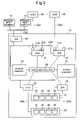
- FIG. 3 is a block diagram showing a general overview of a disk array device 10 .
- the disk array device 10 can be connected respectively to a plurality of host computers 30 , in a mutually communicable fashion, via a communications network CN 1 .
- the communications network CN 1 is, for example, a LAN, SAN, the Internet or a dedicated circuit, or the like. If a LAN is used, then the data transfer between the host computer 30 and the disk array device 10 is conducted in accordance with a TCP/IP protocol. If a SAN is used, data transfer is conducted between the host computer 30 and the disk array device 10 in accordance with a fiber channel protocol.
- FICON Fibre Connection: registered trademark
- ESCON Enterprise System Connection: registered trademark
- ACONARC Advanced Connection Architecture: registered trademark
- FIBARC Fibre Connection Architecture: registered trademark
- Each of the host computers 30 is constituted, for example, by a server, personal computer, workstation, mainframe computer, or the like.
- the respective host computers 30 are connected via a separate communications network to a plurality of client terminals, which are situated outside the range of the drawing.
- the respective host computers 30 provide services to the respective client terminals, by reading or writing data, from or to the disk array device 10 , in response to requests from the respetive client terminals, for example.
- Each of the CHAs 21 controls data transfer with the respective host computers 30 , and is provided with a communications port 21 A.
- 32 CHAs 21 can be provided in the disk array device 10 .
- a CHA 21 is prepared, for example, in accordance with the type of host computer 30 , such as an open CHA, a main frame CHA, or the like, for example.
- Each CHA 21 receives commands and data requesting data read out, or writing, from the host computer 30 connected respectively thereto, and operates in accordance with the commands received from the host computer 30 .
- the CHA 21 receives a read command from the host computer 30 , this read command is stored in the shared memory 24 .
- the DKA 22 refers to the shared memory 24 occasionally, and if it discovers an unprocessed read command, then it reads out the data from the disk drive 26 , and stores this data in the cache memory 23 .
- the CHA 21 reads out the data transferred to the cache memory 23 , and then transmits the data to the host computer 30 .
- the CHA 21 receives a write command from the host computer 30 , then it stores this write command in the shared memory 24 . Moreover, the CHA 21 stores the received data (user data) to the cache memory 23 . When the CHA 21 has stored the data in the cache memory 23 , it then reports completion of writing to the host computer 30 .
- the DKA 22 reads out the data stored in the cache memory 23 , in accordance with the write command stored in the shared memory 24 , and stores this data in the prescribed disk drive 26 .
- Each of the DKAs 22 may be provided in a plural fashion, for instance, comprising 4 or 8 adapters, in the disk array device 10 .
- Each DKA 22 respectively controls data communications with a particular disk drive 26 .
- the respective DKAs 22 and the respective and the respective disk drives 26 are connected by means of a communications network CN 4 , such as a SAN, for example, and perform data transfer in block units, in accordance with a fiber channel protocol.
- a communications network CN 4 such as a SAN, for example, and perform data transfer in block units, in accordance with a fiber channel protocol.
- Each DKA 22 monitors the state of the corresponding disk drive 26 occasionally, and the result of this monitoring operation is transmitted via the internal network CN 3 , to the SVP 28 .
- the respective CHAs 21 and the respective DKAs 22 are provided respectively with a printed circuit board on which a processor, memory, and the like, are mounted, and a control program stored in the memory, for example, (neither of these elements being depicted in the drawings), and they respectively achieve prescribed functions by means of combined operation of these hardware and software elements.
- the cache memory 23 stores user data, and the like, for example.
- the cache memory 23 is constituted by a non-volatile memory, for example.
- the data to be copied is read out to the cache memory 23 , and it is then transferred from the cache memory 23 to the copy destination, by means of either the CHA 21 or DKA 22 , or alternatively, by means of both the CHA 21 and the DKA 22 .
- the shared memory (or the control memory) 24 is constituted by a non-volatile memory, for example. Control information, management information, and the like, is stored in the shared memory 24 , for example.
- the shared memory 24 and cache memory 23 may respectively be provided in a plural fashion. Furthermore, it is also possible to provide both a cache memory 23 and a shared memory 24 on the same memory board. Alternatively, one portion of the memory may be used as a cache region and another portion thereof may be used as a control region.
- the switching section 25 respectively connects together the respective CHAs 21 , the respective DKAs 22 , the cache memory 23 and the shared memory 24 . Thereby, all of the CHAs 21 and the DKAs 22 may respectively access the cache memory 23 and the shared memory 24 .
- the switching section 25 may be constituted as an ultra-high-speed cross-bar switch, or the like, for example.
- a plurality of disk drives 26 may be installed in the disk array device 10 .
- Each of the disk drives 26 can be realized in the form of a hard disk drive (HDD), a semiconductor memory device, or the like, for example.
- HDD hard disk drive
- semiconductor memory device or the like, for example.
- a disk drive 26 is a physical storage device. Although the situation varies depending on the RAID composition, or the like, a RAID group 27 which is a virtual logical region is constructed on a physical storage region provided by one group of four disk drives 26 , for example. Moreover, one or more virtual logical devices (LU: Logical Unit) can be established in a RAID group 27 .
- LU Logical Unit
- the storage resources used by the disk array device 10 do not all have to be provided inside the disk array device 10 .
- the disk array device 10 is able to incorporate and use storage resources existing externally to the disk array device 10 , exactly as if there were its own storage resources.
- the service processor (SVP) 28 is connected respectively to each of the CHAs 21 and the DKAs 22 , by means of an internal network CN 3 , such as a LAN. Furthermore, the SVP 28 may be connected to a plurality of management terminals 31 , by means of a communications network CN 2 , such as a LAN. The SVP 28 accumulates the respective states inside the disk array device 10 , and provides this information to the management terminal 31 .
- FIG. 4 is a block diagram showing the main composition of a storage system for carrying out back up including generational management information.
- the storage system is constituted by connecting a copy source disk array device 100 provided in the primary site and a copy destination disk array device 200 provided in the secondary site.
- the respective disk array devices 100 , 200 may each be provided with the composition described above with reference to FIG. 2 and FIG. 3 , for example.
- the respective disk array devices 100 and 200 are connected together by means of a communications network CN 11 , such as a SAN, or the like, for example. Furthermore, the respective disk array devices 100 , 200 and the host computers (hereinafter, “hosts”) 30 A, 30 B are connected by means of a communications network CN 12 , such as a LAN, SAN, or the like, for example.
- the host 30 A accesses the disk array device 100 of the primary site.
- the host 30 B accesses the disk array device 200 of the secondary site. Where there is no need to distinguish between the primary host 30 A and the secondary host 30 B, these devices are referred to simply as “host 30 ”.
- the disk array device 100 comprises a main volume 110 , a main pool 120 , a differential transfer section 130 , a snapshot control section 140 , a generational management information storing section 150 , and a generational management information transferring section 160 .
- the main volume 110 is a volume for storing a group of data used by the host 30 A.
- the main pool 120 is a volume for saving data withdrawn from the main volume 110 .
- the differential transfer section 130 serves to transfer the respective differential data in the storage contents of the main volume 110 and the main pool 120 , to the disk array device 200 of the secondary site.
- the differential transfer section 130 may be realized, for example, by means of a processor provided in the CHA 21 executing micro code for differential transfer, for example.
- the snapshot control section 140 manages data by acquiring a snapshot of the main volume 110 , on the basis of an instruction (user instruction) from the host 30 A.
- a snapshot may be a volume snapshot in which the whole of the volume is copied, exactly, or it may be a differential snapshot in which only the differential from the time at which the previous snapshot was created, is controlled.
- the snapshot control section 140 creates a differential snapshot.
- the storage contents of the main volume 110 at a prescribed point in time can be managed by means of a differential bitmap table 151 and a withdrawal destination address management table 152 stored in the generational management information storing section 150 , for example.
- a differential bitmap table 151 and a withdrawal destination address management table 152 stored in the generational management information storing section 150 , for example.
- the generational management information 153 is respectively created for each generation of data.
- the generational management information 153 does not have to be stored in the same storage device, and it may also be stored in a distributed fashion in different storage devices.
- the differential bitmap table 151 can be understood as a table which associates flag information indicating an updated status or a non-updated status, respectively, to each of a plurality of blocks achieved by dividing the main volume 110 into blocks of a prescribed size, for example.
- the withdrawal destination address management table 152 can be constituted by associating each block of the main volume 110 , with a withdrawal address indicating whereabouts in the main pool 120 the data stored in that block is to be withdrawn to, for example.
- the composition of the generational management information 153 illustrated in FIG. 5 is simply an example, and differential snapshots of the main volume 110 can be managed by means of various methods.
- the generational management information transferring section 160 transmits the generational management information 153 stored in the generational management information transferring section storing section 150 , to the disk array device 200 of the secondary site.
- the generational management information transferring section 160 transmits the generational management information 153 at approximately the same timing as that at which the differential transfer section 130 transmits the respective differential data of the main volume 110 and the main pool 120 .
- the secondary disk array device 200 may comprise a secondary volume 210 , a secondary pool 220 , a virtual volume creating section 230 , a virtual volume 240 , a generational management information storing section 250 , and a generational management information duplicating section 260 .
- the secondary volume 210 forms a copy pair with the main volume 110 .
- the storage contents of the main volume 110 are copied to the secondary volume 210 .
- the secondary pool 220 forms a copy pair with the main pool 120 .
- the storage contents of the main pool 120 are copied to the secondary pool 220 .
- the virtual volume creating section 230 generates a virtual volume 240 for the designated generation, on the basis of an instruction from the host 30 .
- the virtual volume creating section 230 refers to the secondary volume 210 and the secondary pool 220 , on the basis of the generational management information 253 stored in the generational management information storing section 250 , and creates a virtual volume 240 which reproduces the storage contents of the designated generation, in a virtual manner.
- the generational management information storing section 250 stores the generational management information 253 .
- This generational management information 253 is a copy of the generational management information 153 of the primary site. Therefore, the generational management information 253 comprises, for example, a differential bitmap table 251 , which is a copy of the differential bitmap table 151 , and a withdrawal destination address management table 252 which is a copy of the withdrawal destination address management table 152 .
- the generational management information duplicating section 260 stores the generational management information 253 in the generational management information storing section 250 , on the basis of data received from the generational management information transferring section 160 of the primary site. As described hereinafter, the generational management information duplicating section 260 establishes and manages a storage destination address for the generational management information 253 , on the basis of the data size of the generational management information 153 reported by the generational management information transferring section 160 . The storage destination of the generational management information 253 is recorded in the generational management information storage destination address information 261 .
- FIG. 6 is an illustrative diagram showing a schematic view of the process of storing generational management information 253 in the generational management information storing section 250 .
- the respective partial information elements (differential bitmap table 151 , withdrawal destination address management table 152 ) constituting the generational management information 153 are stored respectively in a distributed fashion, in the disk array device 100 of the primary site.
- the differential bitmap table 151 is stored in the cache memory of the disk array device 100 .
- the withdrawal destination address management table 152 is stored in a prescribed disk.
- the generational management information transferring section 160 acquires the respective data sizes of the differential bitmap table 151 and the withdrawal destination address management table 152 constituting the generational management information 153 , when transferring the generational management information 153 .
- the generational management information transferring section 160 previously reports the data sizes of the respective tables 151 , 152 , to the generational management information duplicating section 260 , before transferring the generational management information 153 .
- the generational management information duplicating section 260 Upon receiving the data sizes of the respective tables 151 , 152 , the generational management information duplicating section 260 reserves the storage region required for copying the generational management information 153 , in the generational management information storing section 250 .
- the generational management information duplicating section 260 stores a differential bitmap table 251 , which is a copy of the differential bitmap table 151 , and a withdrawal destination address management table 252 , which is a copy of the withdrawal destination address management table 152 , respectively, in the reserved storage region.
- the generational management information duplicating section 260 records the storage positions of the respective tables 251 , 252 , in the generational management information storage destination address information 261 .
- the generational management information storage destination address information 261 is formed by associating, for example, the name of the element constituting the generational management information (the name of the partial information), information for identifying the destination storage device (for example, the device number, or the like), a header address, and a data size.
- FIG. 6 shows a case where the respective tables 151 , 152 stored in a distributed fashion in the disk array device 100 are stored together in the cache memory of the disk array device 200 . It is also possible to adopt a composition wherein the tables 251 , 252 in the generational management information 253 are stored in a distributed fashion in the disk array device 200 .
- the storage destination device in the generational management information 253 is not limited to being a cache memory, and may also be one or a plurality of disks.
- FIG. 7 is a flowchart showing an overview of back-up processing for backing up data to a secondary site, including the generational management carried out in the primary site.
- the disk array device 100 transfer the storage contents of the main volume 110 , to the disk array device 200 (S 11 ). Thereupon, the disk array device 100 transfers the storage contents of the main pool 120 to the disk array device 200 (S 12 ).
- the disk array device 200 of the secondary site Upon receiving the data of the main volume 110 , the disk array device 200 of the secondary site stores this data in a prescribed position of the secondary volume 210 , and thereby creates a copy of the main volume 110 (S 21 ). Moreover, upon receiving the data of the main pool 120 , the disk array device 200 of the secondary site stores this data in a prescribed position of the secondary pool 220 , and thereby creates a copy of the main pool 120 (S 22 ).
- the disk array device 100 in the primary site acquires the respective data sizes of the differential bitmap table 151 and the withdrawal destination address management table 152 constituting the generational management information 153 , and it reports these respective data sizes to the disk array device 200 (S 13 ).
- the disk array device 200 of the secondary site reserves the required storage region, on the basis of the data size of the differential bitmap table 151 and the data size of the withdrawal destination address management table 152 .
- the disk array device 200 records the storage destination addresses of the differential bitmap table 251 and the withdrawal destination address management table 252 , in the generational management information storage destination address information 261 (S 23 ).
- the disk array device 100 in the primary site transmits the data of the differential bitmap table 151 and the withdrawal destination address management table 152 constituting the generational management information 153 , respectively, to the disk array device 200 (S 14 ).
- the disk array device 200 in the secondary site creates respective copies of the differential bitmap table 151 and the withdrawal destination address management table 152 , on the basis of the data thus received, and it stores these copies at prescribed positions in the generational management information storing section 250 (S 24 ).
- the disk array device 100 of the primary site monitors data update requests from the host 30 (S 15 ). If there has been an update request (S 15 : YES), then the disk array device 100 manages the differential generated by this update (S 16 ). If, for example, the amount of differential data reaches a prescribed volume, or if a prescribed transfer timing has been reached, (S 17 : YES), then the disk array device 100 repeats the processing in S 11 -S 14 .
- the differential management carried out in S 16 will be described in simple terms.
- the disk array device 100 refers to the differential bitmap table 151 which manages the most recent snapshot of the main volume 110 . If the update flag for the data block to be updated has already been set to on (set to “1”), then the original data stored in that data block has already been withdrawn to the main pool 120 . Consequently, in this case, the disk array device 100 writes over the new data, without withdrawing the data in the main volume 110 .
- the disk array device 100 If the update flag for the data block to be updated is set to off (if it is set to “0”), then it is necessary for the data stored in that data block to be withdrawn before overwriting the data. Therefore, the disk array device 100 reads out the data stored in the data block to be copied, from the main volume 110 , and copied the data to the main pool 120 . Once copying has been completed, the disk array device 100 records the withdrawal destination address of the data, in the withdrawal destination address management table 152 . Furthermore, the disk array device 100 sets the update flag for that block in the differential bitmap table 151 , to on.
- FIG. 8 is a flowchart showing an overview of generation restore processing. Firstly, the disk array device 200 in the secondary site monitors whether or not there has been an instruction to restore a data generation, from the host 30 (S 31 ).
- the disk array device 200 refers to the generational management information storage destination address information 261 , and acquires the respective storage addresses of the differential bitmap table 251 and the withdrawal destination address management table 252 (S 32 ).
- the disk array device 200 acquires the generational management information 253 (the differential bitmap table 251 and the withdrawal destination address management table 252 ), from the generational management information storing section 250 (S 33 ).
- the disk array device 200 creates a virtual volume 240 of the generation designated by the host 30 , from the storage contents of the secondary volume 210 and the secondary pool 220 (S 34 ).
- the virtual volume 240 is, for example, a read out conversion table for restoring the storage contents of the designated generation, in a virtual fashion. It is recorded in the virtual volume 240 which of the secondary volume 210 and the secondary pool 220 the target data is stored in. If the target data is stored in the secondary volume 210 , then this data is read out from the secondary volume 210 . If the target data is stored in the secondary pool 220 , then this data is read out from the secondary pool 220 .
- the disk array device 200 When creating a virtual volume 240 for the designated generation, the disk array device 200 causes all or a portion of that virtual volume 240 to be transmitted to the disk array device 100 in the primary site (S 35 ).
- the disk array device 100 in the primary site then stores the data received from the disk array device 200 of the secondary site, in the main volume 110 (S 41 ).
- the present embodiment has the following beneficial effects.
- a composition was adopted wherein the generational management information in the copy source is also backed up to the copy destination. Therefore, it is possible to manage the back-up data for a plurality of generations, in the back-up destination (copy destination) also. By this means, protection against failure can be increased.
- a composition is adopted wherein management of a plurality of data generations is carried out on the basis of differential snapshots, in the disk array device 100 in the copy source, and all data, including the generational management information 153 for these respective generations, is backed up to the disk array device 200 in the copy source. Therefore, it is possible to manage a plurality of data generations by means of a small volume data capacity, in comparison with cases where the whole volume is copied for each generation.
- a second embodiment is now described on the basis of FIG. 9 .
- the present embodiment is equivalent to a modification example of the first embodiment.
- the characteristic feature of the present embodiment lies in the fact that only the back-up data for a previously designated generation is transferred to the secondary site and held in same.
- FIG. 9 is a flowchart showing an overview of back-up processing. Firstly, the disk array device 100 of the primary site acquires the generation to be backed up (S 51 ). The generation for which data is to be backed up can be instructed to the disk array device 100 by the host 30 .
- the disk array device 100 transmits the respective storage contents of the main volume 110 and the main pool 120 , to the disk array device 200 in the secondary site (S 52 , S 53 ). Thereupon, the disk array device 100 respective acquires the data sizes of the differential bitmap table 151 and the withdrawal destination address management table 152 contained in the generational management information 153 relating to the designated generation. The disk array device 100 respectively reports the data sizes of the tables 151 , 152 , to the disk array device 200 (S 54 ). The disk array device 100 transmits the contents of the differential bitmap table 151 and the withdrawal destination address management table 152 relating to the designated generation, to the disk array device 200 (S 55 ).
- the disk array device 100 monitors update requests from the host 30 (S 56 ), and if an update request has been issued, then the differential generated in the main volume 110 is managed (S 57 ). When a prescribed transfer timing has arrived (S 58 : YES), the disk array device 100 repeats the processing in steps S 52 -S 55 .
- the generational management information 153 or the like, relating to the generation designated by the host 30 , to the disk array device 200 of the secondary site, and hence ease of use is improved.
- a composition is adopted wherein, when the storage contents of the main pool 120 are transferred to the disk array device 200 , only the portion relating to the storage contents of a generation designated by the user is transferred.
- a third embodiment is now described on the basis of FIG. 10 and FIG. 11 .
- the present embodiment is equivalent to a modification example of the first embodiment.
- the characteristic feature of the present embodiment lies in the fact that copies of a main volume, a main pool, and respective generational management information, held in the copy destination are transferred to the copy source, on the basis of an instruction from the user.
- FIG. 10 is an approximate block diagram showing the general composition of a storage system.
- the disk array device 200 in the secondary site comprises a restoring section 270 .
- the virtual volume creating section 230 is omitted from the drawing.
- the restoring section 270 respectively transfers the storage contents of the secondary volume 210 , the storage contents of the secondary pool 220 , and the generational management information 253 , to the disk array device 100 of the primary site, thereby respectively restoring the main volume 110 , the main pool 120 and the generational management information 153 .
- FIG. 11 is a flowchart showing an overview of restore processing.
- the disk array device 200 of the secondary site detects a restore instruction from the host 30 (S 61 : YES), it transfers the storage contents of the secondary volume 210 to the disk array device 100 (S 62 ).
- the disk array device 100 of the primary site stores the data received from the disk array device 200 , in the main volume 110 , and thereby restores the main volume 110 (S 71 ).
- the disk array device 200 of the secondary site transfers the storage contents of the secondary pool 220 to the disk array device 100 (S 63 ).
- the disk array device 100 of the primary site stores the data received from the disk array device 200 , in the main pool 120 , and thereby restores the main pool 120 (S 72 ).
- the disk array device 200 refers to the generational management information storage address information 261 , and acquires the storage address of the generational management information 253 (S 64 ).
- the disk array device 200 respectively acquires the differential bitmap table 251 and the withdrawal destination address management table 252 , from the generational management information storing section 250 , on the basis of the acquired address (S 65 ).
- the disk array device 200 transmits the contents of the differential bitmap table 251 and the withdrawal destination address management table 252 , respectively, to the disk array device 100 (S 66 ).
- the disk array device 100 of the primary site stores the data received from the disk array device 200 , in a prescribed position of the generational management information storing section 150 , and thereby restores the generational management information 153 (S 73 ).
- the copies of the main volume 110 and the main pool 120 and the copy of generational management information 153 held in the copy destination disk array device 200 are respectively returned to the copy source disk array device 100 .
Abstract
Description
Claims (14)
Priority Applications (1)
| Application Number | Priority Date | Filing Date | Title |
|---|---|---|---|
| US11/878,268 US7716438B2 (en) | 2004-03-31 | 2007-07-23 | Storage system and back-up method for storage system |
Applications Claiming Priority (4)
| Application Number | Priority Date | Filing Date | Title |
|---|---|---|---|
| JP2004102377A JP2005292865A (en) | 2004-03-31 | 2004-03-31 | Storage system and backup method for storage system |
| JP2004-102377 | 2004-03-31 | ||
| US10/852,218 US7272693B2 (en) | 2004-03-31 | 2004-05-25 | Storage system and back-up method for storage system |
| US11/878,268 US7716438B2 (en) | 2004-03-31 | 2007-07-23 | Storage system and back-up method for storage system |
Related Parent Applications (1)
| Application Number | Title | Priority Date | Filing Date |
|---|---|---|---|
| US10/852,218 Continuation US7272693B2 (en) | 2004-03-31 | 2004-05-25 | Storage system and back-up method for storage system |
Publications (2)
| Publication Number | Publication Date |
|---|---|
| US20070266213A1 US20070266213A1 (en) | 2007-11-15 |
| US7716438B2 true US7716438B2 (en) | 2010-05-11 |
Family
ID=35055720
Family Applications (2)
| Application Number | Title | Priority Date | Filing Date |
|---|---|---|---|
| US10/852,218 Active 2024-09-25 US7272693B2 (en) | 2004-03-31 | 2004-05-25 | Storage system and back-up method for storage system |
| US11/878,268 Active 2024-12-28 US7716438B2 (en) | 2004-03-31 | 2007-07-23 | Storage system and back-up method for storage system |
Family Applications Before (1)
| Application Number | Title | Priority Date | Filing Date |
|---|---|---|---|
| US10/852,218 Active 2024-09-25 US7272693B2 (en) | 2004-03-31 | 2004-05-25 | Storage system and back-up method for storage system |
Country Status (2)
| Country | Link |
|---|---|
| US (2) | US7272693B2 (en) |
| JP (1) | JP2005292865A (en) |
Cited By (6)
| Publication number | Priority date | Publication date | Assignee | Title |
|---|---|---|---|---|
| US20120324300A1 (en) * | 2010-03-08 | 2012-12-20 | Nec Corporation | Computer system, active system computer, and standby system computer |
| WO2016101819A1 (en) * | 2014-12-22 | 2016-06-30 | 华为技术有限公司 | Data backup and recovery method, device and server thereof |
| US10372546B2 (en) | 2014-02-07 | 2019-08-06 | International Business Machines Corporation | Creating a restore copy from a copy of source data in a repository having source data at different point-in-times |
| US10387446B2 (en) | 2014-04-28 | 2019-08-20 | International Business Machines Corporation | Merging multiple point-in-time copies into a merged point-in-time copy |
| US11169958B2 (en) | 2014-02-07 | 2021-11-09 | International Business Machines Corporation | Using a repository having a full copy of source data and point-in-time information from point-in-time copies of the source data to restore the source data at different points-in-time |
| US11194667B2 (en) | 2014-02-07 | 2021-12-07 | International Business Machines Corporation | Creating a restore copy from a copy of a full copy of source data in a repository that is at a different point-in-time than a restore point-in-time of a restore request |
Families Citing this family (37)
| Publication number | Priority date | Publication date | Assignee | Title |
|---|---|---|---|---|
| US7643195B2 (en) * | 2003-11-01 | 2010-01-05 | Silicon Quest Kabushiki-Kaisha | Mirror device |
| JP4401895B2 (en) * | 2004-08-09 | 2010-01-20 | 株式会社日立製作所 | Computer system, computer and its program. |
| JP4641528B2 (en) * | 2004-11-25 | 2011-03-02 | 富士通株式会社 | Data writing program and data writing method |
| US7818350B2 (en) * | 2005-02-28 | 2010-10-19 | Yahoo! Inc. | System and method for creating a collaborative playlist |
| CN100447758C (en) * | 2005-12-14 | 2008-12-31 | 英业达股份有限公司 | Snapshot management method for logic disk |
| JP4800031B2 (en) * | 2005-12-28 | 2011-10-26 | 株式会社日立製作所 | Storage system and snapshot management method |
| JP4741371B2 (en) * | 2006-01-05 | 2011-08-03 | 株式会社日立製作所 | System, server apparatus, and snapshot format conversion method |
| US7457934B2 (en) * | 2006-03-22 | 2008-11-25 | Hitachi, Ltd. | Method and apparatus for reducing the amount of data in a storage system |
| US9317222B1 (en) | 2006-04-24 | 2016-04-19 | Emc Corporation | Centralized content addressed storage |
| US9235477B1 (en) | 2006-04-24 | 2016-01-12 | Emc Corporation | Virtualized backup solution |
| US9684739B1 (en) | 2006-05-11 | 2017-06-20 | EMC IP Holding Company LLC | View generator for managing data storage |
| JP4839133B2 (en) * | 2006-05-22 | 2011-12-21 | 株式会社日立製作所 | Data management method and computer system for storage apparatus |
| JP2007334709A (en) | 2006-06-16 | 2007-12-27 | Fujitsu Ltd | Storage control device, storage control program, and storage control method |
| US8006049B2 (en) * | 2007-01-18 | 2011-08-23 | International Business Machines Corporation | Export of logical volumes by pools |
| US20080282047A1 (en) * | 2007-05-08 | 2008-11-13 | Hitachi, Ltd. | Methods and apparatus to backup and restore data for virtualized storage area |
| US8296534B1 (en) * | 2007-06-29 | 2012-10-23 | Emc Corporation | Techniques for using flash-based memory in recovery processing |
| JP5028218B2 (en) * | 2007-10-30 | 2012-09-19 | 株式会社日立製作所 | Storage control device, storage system, and storage control device control method |
| JP5228466B2 (en) * | 2007-12-14 | 2013-07-03 | 富士通株式会社 | Backup device, backup method and backup program |
| JP2009181206A (en) * | 2008-01-29 | 2009-08-13 | Hitachi Ltd | Storage system and snapshot configuration migration method |
| JP4886918B1 (en) | 2008-10-30 | 2012-02-29 | インターナショナル・ビジネス・マシーンズ・コーポレーション | Method for processing a flashcopy process, and system and computer program therefor |
| JP5251690B2 (en) * | 2009-04-02 | 2013-07-31 | 日本電気株式会社 | Remote copy system and remote copy method |
| JP2012058863A (en) | 2010-09-07 | 2012-03-22 | Nec Corp | Disk device and method and program for data duplication to disk device |
| US20120117303A1 (en) * | 2010-11-04 | 2012-05-10 | Numonyx B.V. | Metadata storage associated with flash translation layer |
| JP5772443B2 (en) * | 2011-09-22 | 2015-09-02 | 富士通株式会社 | Storage apparatus and program |
| US9323461B2 (en) * | 2012-05-01 | 2016-04-26 | Hitachi, Ltd. | Traffic reducing on data migration |
| JP6070146B2 (en) | 2012-12-14 | 2017-02-01 | 富士通株式会社 | Information processing apparatus and backup method |
| JP6064608B2 (en) | 2013-01-17 | 2017-01-25 | 富士通株式会社 | Storage device, backup program, and backup method |
| JPWO2014112062A1 (en) * | 2013-01-17 | 2017-01-19 | 株式会社日立製作所 | Storage apparatus and data migration method |
| JP6277878B2 (en) * | 2014-06-16 | 2018-02-14 | 富士通株式会社 | Storage device control device, storage device control method, and storage device control program |
| JP5991699B2 (en) | 2014-08-08 | 2016-09-14 | インターナショナル・ビジネス・マシーンズ・コーポレーションInternational Business Machines Corporation | Information processing apparatus, information processing system, backup method, and program |
| JP6237925B2 (en) * | 2014-10-23 | 2017-11-29 | 日本電気株式会社 | Cluster system and cluster control method |
| JP6281511B2 (en) * | 2015-03-24 | 2018-02-21 | 日本電気株式会社 | BACKUP CONTROL DEVICE, BACKUP CONTROL METHOD, AND PROGRAM |
| WO2016153497A1 (en) * | 2015-03-25 | 2016-09-29 | Hitachi, Ltd. | Method and apparatus for remote copy between enterprise storage and commodity hardware based software storage |
| CN107577558B (en) * | 2017-08-31 | 2021-03-09 | 苏州浪潮智能科技有限公司 | Cloud storage snapshot method and device |
| CN109787895B (en) * | 2019-03-29 | 2020-10-27 | 烽火通信科技股份有限公司 | Dual-homing protection method, access node, equipment and communication network |
| US11354268B2 (en) * | 2020-01-08 | 2022-06-07 | EMC IP Holding Company LLC | Optimizing snapshot creation |
| US20230418961A1 (en) * | 2022-06-28 | 2023-12-28 | International Business Machines Corporation | Fine granularity read access to generational safeguarded copy data |
Citations (29)
| Publication number | Priority date | Publication date | Assignee | Title |
|---|---|---|---|---|
| JPS61217864A (en) | 1985-03-23 | 1986-09-27 | Brother Ind Ltd | Electronic dictionary |
| JPH08166854A (en) | 1994-12-15 | 1996-06-25 | Hitachi Ltd | Managing method for saved volume |
| JPH0950394A (en) | 1995-08-08 | 1997-02-18 | Fuji Facom Corp | Automatic data saving processing system |
| JPH09101912A (en) | 1995-10-06 | 1997-04-15 | Mitsubishi Electric Corp | Difference backup system |
| JPH11162106A (en) | 1997-11-21 | 1999-06-18 | Matsushita Electric Ind Co Ltd | Recording and reproducing apparatus |
| JPH11213639A (en) | 1997-08-06 | 1999-08-06 | Sony Corp | Distribution system, distribution method, receiving apparatus and receiving method |
| JPH11259348A (en) | 1998-01-26 | 1999-09-24 | Internatl Business Mach Corp <Ibm> | Device and method for performing snap shot copy of volume |
| JP2000163277A (en) | 1998-12-01 | 2000-06-16 | Fujitsu Ltd | Method for data transfer between dasd controllers |
| JP2001051856A (en) | 1999-08-10 | 2001-02-23 | Toshiba Corp | Common memory and common memory managing device |
| JP2001051806A (en) | 1999-08-05 | 2001-02-23 | Fujitsu Ltd | Disk array device |
| JP2001166887A (en) | 1999-12-08 | 2001-06-22 | Sony Corp | Data recording and reproducing device and data recording and reproducing method |
| US6269381B1 (en) | 1998-06-30 | 2001-07-31 | Emc Corporation | Method and apparatus for backing up data before updating the data and for restoring from the backups |
| JP2001236258A (en) | 1999-12-16 | 2001-08-31 | Hitachi Ltd | Storage controller |
| US20010049776A1 (en) | 2000-06-02 | 2001-12-06 | Fujitsu Limited | Method and apparatus for inter-disk copy processing, and a computer product |
| JP2002007304A (en) | 2000-06-23 | 2002-01-11 | Hitachi Ltd | Computer system using storage area network and data handling method therefor |
| US20020010762A1 (en) | 2000-06-30 | 2002-01-24 | Shoji Kodama | File sharing system with data mirroring by storage systems |
| JP2002023957A (en) | 2000-07-04 | 2002-01-25 | Matsushita Electric Ind Co Ltd | Recording and reproducing device |
| JP2002055783A (en) | 2000-06-02 | 2002-02-20 | Fujitsu Ltd | Inter-disk copy processor and copy processing method and program allowing the same method to be performed by computer and computer readable recording medium with its program recorded |
| US6434683B1 (en) | 2000-11-07 | 2002-08-13 | Storage Technology Corporation | Method and system for transferring delta difference data to a storage device |
| JP2002278819A (en) | 2001-03-21 | 2002-09-27 | Toshiba Corp | Generation management method for snap shot image, storage medium and generation management system |
| US20020169901A1 (en) | 2001-05-09 | 2002-11-14 | Hitachi. Ltd. | Computer system using disk controller and operating service thereof |
| JP2002358222A (en) | 2001-06-04 | 2002-12-13 | Hitachi Ltd | Data dual system and method |
| JP2003006016A (en) | 2001-06-26 | 2003-01-10 | Hitachi Ltd | Disk subsystem and method of asynchronous copy between disk subsystems |
| US6651075B1 (en) | 2000-02-16 | 2003-11-18 | Microsoft Corporation | Support for multiple temporal snapshots of same volume |
| US6684306B1 (en) | 1999-12-16 | 2004-01-27 | Hitachi, Ltd. | Data backup in presence of pending hazard |
| JP2004046435A (en) | 2002-07-10 | 2004-02-12 | Hitachi Ltd | Backup method and storage controller used for the same |
| US20040093361A1 (en) | 2002-09-10 | 2004-05-13 | Therrien David G. | Method and apparatus for storage system to provide distributed data storage and protection |
| US6779003B1 (en) | 1999-12-16 | 2004-08-17 | Livevault Corporation | Systems and methods for backing up data files |
| US6912629B1 (en) * | 1999-07-28 | 2005-06-28 | Storage Technology Corporation | System and method for restoring data from secondary volume to primary volume in a data storage system |
-
2004
- 2004-03-31 JP JP2004102377A patent/JP2005292865A/en active Pending
- 2004-05-25 US US10/852,218 patent/US7272693B2/en active Active
-
2007
- 2007-07-23 US US11/878,268 patent/US7716438B2/en active Active
Patent Citations (33)
| Publication number | Priority date | Publication date | Assignee | Title |
|---|---|---|---|---|
| JPS61217864A (en) | 1985-03-23 | 1986-09-27 | Brother Ind Ltd | Electronic dictionary |
| JPH08166854A (en) | 1994-12-15 | 1996-06-25 | Hitachi Ltd | Managing method for saved volume |
| JPH0950394A (en) | 1995-08-08 | 1997-02-18 | Fuji Facom Corp | Automatic data saving processing system |
| JPH09101912A (en) | 1995-10-06 | 1997-04-15 | Mitsubishi Electric Corp | Difference backup system |
| US5720026A (en) | 1995-10-06 | 1998-02-17 | Mitsubishi Denki Kabushiki Kaisha | Incremental backup system |
| JPH11213639A (en) | 1997-08-06 | 1999-08-06 | Sony Corp | Distribution system, distribution method, receiving apparatus and receiving method |
| JPH11162106A (en) | 1997-11-21 | 1999-06-18 | Matsushita Electric Ind Co Ltd | Recording and reproducing apparatus |
| JPH11259348A (en) | 1998-01-26 | 1999-09-24 | Internatl Business Mach Corp <Ibm> | Device and method for performing snap shot copy of volume |
| US6269381B1 (en) | 1998-06-30 | 2001-07-31 | Emc Corporation | Method and apparatus for backing up data before updating the data and for restoring from the backups |
| JP2000163277A (en) | 1998-12-01 | 2000-06-16 | Fujitsu Ltd | Method for data transfer between dasd controllers |
| US6912629B1 (en) * | 1999-07-28 | 2005-06-28 | Storage Technology Corporation | System and method for restoring data from secondary volume to primary volume in a data storage system |
| JP2001051806A (en) | 1999-08-05 | 2001-02-23 | Fujitsu Ltd | Disk array device |
| JP2001051856A (en) | 1999-08-10 | 2001-02-23 | Toshiba Corp | Common memory and common memory managing device |
| JP2001166887A (en) | 1999-12-08 | 2001-06-22 | Sony Corp | Data recording and reproducing device and data recording and reproducing method |
| JP2001236258A (en) | 1999-12-16 | 2001-08-31 | Hitachi Ltd | Storage controller |
| US6779003B1 (en) | 1999-12-16 | 2004-08-17 | Livevault Corporation | Systems and methods for backing up data files |
| US6684306B1 (en) | 1999-12-16 | 2004-01-27 | Hitachi, Ltd. | Data backup in presence of pending hazard |
| US6651075B1 (en) | 2000-02-16 | 2003-11-18 | Microsoft Corporation | Support for multiple temporal snapshots of same volume |
| US20010049776A1 (en) | 2000-06-02 | 2001-12-06 | Fujitsu Limited | Method and apparatus for inter-disk copy processing, and a computer product |
| US6636954B2 (en) | 2000-06-02 | 2003-10-21 | Fujitsu Limited | Method and apparatus for inter-disk copy processing, and a computer product |
| JP2002055783A (en) | 2000-06-02 | 2002-02-20 | Fujitsu Ltd | Inter-disk copy processor and copy processing method and program allowing the same method to be performed by computer and computer readable recording medium with its program recorded |
| JP2002007304A (en) | 2000-06-23 | 2002-01-11 | Hitachi Ltd | Computer system using storage area network and data handling method therefor |
| US20020010762A1 (en) | 2000-06-30 | 2002-01-24 | Shoji Kodama | File sharing system with data mirroring by storage systems |
| JP2002023957A (en) | 2000-07-04 | 2002-01-25 | Matsushita Electric Ind Co Ltd | Recording and reproducing device |
| US6434683B1 (en) | 2000-11-07 | 2002-08-13 | Storage Technology Corporation | Method and system for transferring delta difference data to a storage device |
| JP2002278819A (en) | 2001-03-21 | 2002-09-27 | Toshiba Corp | Generation management method for snap shot image, storage medium and generation management system |
| JP2002333956A (en) | 2001-05-09 | 2002-11-22 | Hitachi Ltd | Computer system using disk controller and its operation service |
| US20020169901A1 (en) | 2001-05-09 | 2002-11-14 | Hitachi. Ltd. | Computer system using disk controller and operating service thereof |
| JP2002358222A (en) | 2001-06-04 | 2002-12-13 | Hitachi Ltd | Data dual system and method |
| JP2003006016A (en) | 2001-06-26 | 2003-01-10 | Hitachi Ltd | Disk subsystem and method of asynchronous copy between disk subsystems |
| JP2004046435A (en) | 2002-07-10 | 2004-02-12 | Hitachi Ltd | Backup method and storage controller used for the same |
| US20060253734A1 (en) | 2002-07-10 | 2006-11-09 | Hitachi, Ltd. | Backup method and storage control device using the same |
| US20040093361A1 (en) | 2002-09-10 | 2004-05-13 | Therrien David G. | Method and apparatus for storage system to provide distributed data storage and protection |
Cited By (10)
| Publication number | Priority date | Publication date | Assignee | Title |
|---|---|---|---|---|
| US20120324300A1 (en) * | 2010-03-08 | 2012-12-20 | Nec Corporation | Computer system, active system computer, and standby system computer |
| US9128903B2 (en) * | 2010-03-08 | 2015-09-08 | Nec Corporation | Computer system, active system computer, and standby system computer |
| US10372546B2 (en) | 2014-02-07 | 2019-08-06 | International Business Machines Corporation | Creating a restore copy from a copy of source data in a repository having source data at different point-in-times |
| US11150994B2 (en) | 2014-02-07 | 2021-10-19 | International Business Machines Corporation | Creating a restore copy from a copy of source data in a repository having source data at different point-in-times |
| US11169958B2 (en) | 2014-02-07 | 2021-11-09 | International Business Machines Corporation | Using a repository having a full copy of source data and point-in-time information from point-in-time copies of the source data to restore the source data at different points-in-time |
| US11194667B2 (en) | 2014-02-07 | 2021-12-07 | International Business Machines Corporation | Creating a restore copy from a copy of a full copy of source data in a repository that is at a different point-in-time than a restore point-in-time of a restore request |
| US10387446B2 (en) | 2014-04-28 | 2019-08-20 | International Business Machines Corporation | Merging multiple point-in-time copies into a merged point-in-time copy |
| US11630839B2 (en) | 2014-04-28 | 2023-04-18 | International Business Machines Corporation | Merging multiple point-in-time copies into a merged point-in-time copy |
| WO2016101819A1 (en) * | 2014-12-22 | 2016-06-30 | 华为技术有限公司 | Data backup and recovery method, device and server thereof |
| US10082982B2 (en) | 2014-12-22 | 2018-09-25 | Huawei Technologies Co., Ltd. | Data backup method and apparatus, data restoration method and apparatus, and server |
Also Published As
| Publication number | Publication date |
|---|---|
| US20050223170A1 (en) | 2005-10-06 |
| JP2005292865A (en) | 2005-10-20 |
| US7272693B2 (en) | 2007-09-18 |
| US20070266213A1 (en) | 2007-11-15 |
Similar Documents
| Publication | Publication Date | Title |
|---|---|---|
| US7716438B2 (en) | Storage system and back-up method for storage system | |
| US7451287B2 (en) | Storage system and remote copy method for storage system | |
| US7111192B2 (en) | Method for operating storage system including a main site and a backup | |
| US7689799B2 (en) | Method and apparatus for identifying logical volumes in multiple element computer storage domains | |
| US7107395B1 (en) | Apparatus and methods for operating a computer storage system | |
| US7428604B2 (en) | Method and apparatus for moving logical entities among storage elements in a computer storage system | |
| US6708265B1 (en) | Method and apparatus for moving accesses to logical entities from one storage element to another storage element in a computer storage system | |
| US6487561B1 (en) | Apparatus and methods for copying, backing up, and restoring data using a backup segment size larger than the storage block size | |
| US6920537B2 (en) | Apparatus and methods for copying, backing up and restoring logical objects in a computer storage system by transferring blocks out of order or in parallel | |
| US6397308B1 (en) | Apparatus and method for differential backup and restoration of data in a computer storage system | |
| US7716261B2 (en) | Method and apparatus for verifying storage access requests in a computer storage system with multiple storage elements | |
| US6385706B1 (en) | Apparatus and methods for copying a logical object to a primary storage device using a map of storage locations | |
| US8341199B2 (en) | Storage system, a method of file data back up and a method of copying of file data | |
| US6549992B1 (en) | Computer data storage backup with tape overflow control of disk caching of backup data stream | |
| US7653792B2 (en) | Disk array apparatus including controller that executes control to move data between storage areas based on a data protection level | |
| US7899933B1 (en) | Use of global logical volume identifiers to access logical volumes stored among a plurality of storage elements in a computer storage system | |
| US7107417B2 (en) | System, method and apparatus for logical volume duplexing in a virtual tape system | |
| US7243256B2 (en) | External storage and data recovery method for external storage as well as program | |
| US9058305B2 (en) | Remote copy method and remote copy system | |
| US6912548B1 (en) | Logical volume identifier database for logical volumes in a computer storage system | |
| US6275897B1 (en) | Remote cache utilization for mirrored mass storage subsystem | |
| US6760828B1 (en) | Method and apparatus for using logical volume identifiers for tracking or identifying logical volume stored in the storage system | |
| US7243188B2 (en) | Method and apparatus for maintaining inventory of logical volumes stored on storage elements | |
| US20050223180A1 (en) | Accelerating the execution of I/O operations in a storage system | |
| JP2008033967A (en) | External storage device and method for restoring data of external storage device and program |
Legal Events
| Date | Code | Title | Description |
|---|---|---|---|
| AS | Assignment |
Owner name: HITACHI, LTD., JAPAN Free format text: ASSIGNMENT OF ASSIGNORS INTEREST;ASSIGNORS:USHIJIMA, TAKUMA;KUMAGAI, MASATO;SATO, EIICHI;AND OTHERS;REEL/FRAME:019663/0583 Effective date: 20040525 Owner name: HITACHI, LTD.,JAPAN Free format text: ASSIGNMENT OF ASSIGNORS INTEREST;ASSIGNORS:USHIJIMA, TAKUMA;KUMAGAI, MASATO;SATO, EIICHI;AND OTHERS;REEL/FRAME:019663/0583 Effective date: 20040525 |
|
| STCF | Information on status: patent grant |
Free format text: PATENTED CASE |
|
| FEPP | Fee payment procedure |
Free format text: PAYER NUMBER DE-ASSIGNED (ORIGINAL EVENT CODE: RMPN); ENTITY STATUS OF PATENT OWNER: LARGE ENTITY Free format text: PAYOR NUMBER ASSIGNED (ORIGINAL EVENT CODE: ASPN); ENTITY STATUS OF PATENT OWNER: LARGE ENTITY |
|
| FPAY | Fee payment |
Year of fee payment: 4 |
|
| AS | Assignment |
Owner name: GLOBAL D, LLC, JAPAN Free format text: ASSIGNMENT OF ASSIGNORS INTEREST;ASSIGNOR:HITACHI, LTD.;REEL/FRAME:032446/0285 Effective date: 20140307 |
|
| AS | Assignment |
Owner name: RAKUTEN, INC., JAPAN Free format text: ASSIGNMENT OF ASSIGNORS INTEREST;ASSIGNOR:GLOBAL D, LLC.;REEL/FRAME:032503/0237 Effective date: 20140314 |
|
| AS | Assignment |
Owner name: RAKUTEN, INC., JAPAN Free format text: CHANGE OF ADDRESS;ASSIGNOR:RAKUTEN, INC.;REEL/FRAME:037751/0006 Effective date: 20150824 |
|
| MAFP | Maintenance fee payment |
Free format text: PAYMENT OF MAINTENANCE FEE, 8TH YEAR, LARGE ENTITY (ORIGINAL EVENT CODE: M1552) Year of fee payment: 8 |
|
| MAFP | Maintenance fee payment |
Free format text: PAYMENT OF MAINTENANCE FEE, 12TH YEAR, LARGE ENTITY (ORIGINAL EVENT CODE: M1553); ENTITY STATUS OF PATENT OWNER: LARGE ENTITY Year of fee payment: 12 |
|
| AS | Assignment |
Owner name: RAKUTEN GROUP, INC., JAPAN Free format text: CHANGE OF NAME;ASSIGNOR:RAKUTEN, INC.;REEL/FRAME:058314/0657 Effective date: 20210901 |