US7716946B2 - Accumulator with deflector - Google Patents
Accumulator with deflector Download PDFInfo
- Publication number
- US7716946B2 US7716946B2 US12/131,535 US13153508A US7716946B2 US 7716946 B2 US7716946 B2 US 7716946B2 US 13153508 A US13153508 A US 13153508A US 7716946 B2 US7716946 B2 US 7716946B2
- Authority
- US
- United States
- Prior art keywords
- accumulator
- deflector
- initial contact
- contact surface
- liquid
- Prior art date
- Legal status (The legal status is an assumption and is not a legal conclusion. Google has not performed a legal analysis and makes no representation as to the accuracy of the status listed.)
- Expired - Fee Related, expires
Links
Images


Classifications
-
- F—MECHANICAL ENGINEERING; LIGHTING; HEATING; WEAPONS; BLASTING
- F25—REFRIGERATION OR COOLING; COMBINED HEATING AND REFRIGERATION SYSTEMS; HEAT PUMP SYSTEMS; MANUFACTURE OR STORAGE OF ICE; LIQUEFACTION SOLIDIFICATION OF GASES
- F25B—REFRIGERATION MACHINES, PLANTS OR SYSTEMS; COMBINED HEATING AND REFRIGERATION SYSTEMS; HEAT PUMP SYSTEMS
- F25B43/00—Arrangements for separating or purifying gases or liquids; Arrangements for vaporising the residuum of liquid refrigerant, e.g. by heat
- F25B43/006—Accumulators
-
- F—MECHANICAL ENGINEERING; LIGHTING; HEATING; WEAPONS; BLASTING
- F25—REFRIGERATION OR COOLING; COMBINED HEATING AND REFRIGERATION SYSTEMS; HEAT PUMP SYSTEMS; MANUFACTURE OR STORAGE OF ICE; LIQUEFACTION SOLIDIFICATION OF GASES
- F25B—REFRIGERATION MACHINES, PLANTS OR SYSTEMS; COMBINED HEATING AND REFRIGERATION SYSTEMS; HEAT PUMP SYSTEMS
- F25B2400/00—General features or devices for refrigeration machines, plants or systems, combined heating and refrigeration systems or heat-pump systems, i.e. not limited to a particular subgroup of F25B
- F25B2400/03—Suction accumulators with deflectors
Definitions
- the invention relates to suction accumulators for refrigeration or air/conditioning system use and is particularly concerned with deflectors used with accumulators.
- Closed-loop refrigeration systems conventionally employ a compressor that is meant to draw in gaseous refrigerant at relatively low pressure and discharge hot refrigerant at relatively high pressure.
- the hot refrigerant condenses into liquid as it is cooled in a condenser.
- a small orifice or valve divides the system into high and low-pressure sides.
- the liquid on the high-pressure side passes through the orifice or valve and turns into a gas in the evaporator as it picks up heat.
- An accumulator is typically a metal can, welded together, and often has fittings attached for a switch, transducer and/or charge port.
- One or more inlet tubes and an outlet tube pierce the top, sides, or occasionally the bottom, or attach to fittings provided for that purpose.
- the refrigerant flowing into a typical accumulator will impinge upon a deflector or baffle intended to reduce the likelihood of liquid flowing out the exit, generally by removing kinetic energy from the liquid so it settles quietly into the reservoir area without churning or splashing.
- the lack of a deflector reduces effective reservoir volume and reduces efficiency by allowing churning and splashing that returns unnecessary liquid to the compressor—that is, by allowing liquid carryover. Moreover, even when deflectors have been used in the past, the deflectors have contributed to turbulence, when the incoming fluid rebounds off the deflectors.
- a consequence of using a suction line accumulator is that compressor oil can become trapped within it.
- Compressor oil is circulated with the refrigerant in most systems in current usage. Even if a separator is used, a small amount of oil escapes into the system. This oil will find its way into the accumulator, and while liquid refrigerant may be expected to evaporate and return to circulation as needed, the oil does not evaporate. Some means must be provided to return this oil to circulation.
- a known practice is to use a J-shaped outlet tube to carry the exiting gaseous refrigerant from the top of the accumulator down to the bottom and then back up to the outlet from the accumulator.
- J-tube sometimes also referred to as a “U-tube”
- U-tube A carefully sized orifice at the bottom of this “J-tube” (sometimes also referred to as a “U-tube”) entrains the oil from the bottom of the liquid area into the stream of exiting gas.
- a recent development in accumulator design is to incorporate a plastic liner in the accumulator to assist with the oil pick up function (as shown in U.S. Pat. Nos. 6,612,128 and 6,463,757).
- Deflectors within accumulators have typically been designed to act only as shields to protect an outlet tube (or a J-tube or a gas flow tube (all of which may be referred to as a conduit primarily for gas)) from stray liquid refrigerant. It would be desirable to have a deflector that improves the separation of liquid and gas, while also protecting the outlet (or gas flow tube) from liquid refrigerant.
- the geometry of an initial contact surface of a deflector provides for inbound refrigerant and oil to be separated into its liquid and gas components with minimal or less interaction with the initial contact surface.
- the liquid and gas are allowed only minimal interaction upon contact with the deflector to avoid or reduce the likelihood of liquid re-entrainment.
- the liquid refrigerant and oil are then directed towards or near an inner surface of the accumulator, where gravity pulls the liquid down.
- the liquid refrigerant is then directed to interior walls of a liner while the gas flows toward a gas flow conduit.
- the oil and liquid refrigerant flow downward due to gravity, along an inside surface of the liner, to the bottom of the liner, while the gaseous refrigerant migrates toward an inlet of the gas flow conduit.
- the gas flow conduit is designed to direct the gas downward, underneath the liner. As gas flows under the liner, oil is entrained within the gas flow, through an oil bleed orifice located at or near a zenith in the liner.
- a deflector is provided for an accumulator where deflector surfaces disperse a greater amount of kinetic energy (than previous designs), thereby yielding improved gas/liquid separation.
- Embodiments of the accumulators and related designs described herein could be used in air conditioning systems within vehicles. Embodiments of the accumulators and related designs described herein could also be used in stationary air conditioning and/or refrigeration systems (commercial and industrial).
- the invention provides an accumulator for an air conditioning system, the accumulator comprising an outer body, a liner inside and spaced from the outer body, a conduit primarily for gas, and a deflector comprising a generally cylindrical circumference with an inner surface, wherein the inner surface of the circumference of the deflector is adjacent an inside surface of the liner and the deflector further comprising a separation/protection means to separate liquid from gas, wherein a portion of the separation/protection means comprises a barrier to substantially prevent liquid from entering the conduit and a portion of the separation/protection means comprises an initial contact surface for directing fluid away from a flow of incoming fluid, wherein the initial contact surface is substantially convex across the initial contact surface and the initial contact surface, as seen from an upper edge to a lower edge thereof, is angled away from the flow of incoming fluid.
- the invention provides an accumulator for an air conditioning system, the accumulator comprising an inlet to supply incoming fluid, the inlet being located on a side of the accumulator, the accumulator further comprising a deflector and a conduit primarily for gas, the deflector comprising a separation/protection means to separate liquid from gas, wherein the separation/protection means comprises a barrier to substantially prevent liquid from entering the conduit and the separation/protection means comprises an initial contact surface for directing fluid down and away from a flow of incoming fluid, wherein the initial contact surface is substantially convex across the initial contact surface and the initial contact surface, as seen from an upper edge to a lower edge thereof, is angled away from the flow of incoming fluid.
- the invention provides an accumulator for an air conditioning system, the accumulator comprising: a deflector, a conduit primarily for gas, an outer body, an inlet to supply incoming fluid, the inlet being located within a top of the outer body to direct incoming fluid downward, and a separation/protection means to separate liquid from gas
- the separation/protection means comprises a barrier to substantially prevent liquid from entering the conduit and a portion of the separation/protection means comprises an initial contact surface for directing fluid down and away from a flow of incoming fluid, wherein the initial contact surface is located generally opposite the inlet and the initial contact surface is substantially convex across the initial contact surface and slopes downward and outward to direct fluid in a direction away from an entrance of the conduit, and the initial contact surface as seen from an upper edge to a lower edge thereof, is angled away from the flow of incoming fluid
- the barrier of the separation/protection means comprises a wall extending across the deflector, with the inlet being located on one side of the barrier
- FIG. 1 a is a perspective view of a side-in-side-out (SISO) accumulator (with some of the internal components shown in dotted outline) in accordance with an embodiment of the present invention
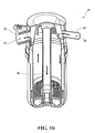
- FIG. 1 b is a vertical sectional view of the accumulator of FIG. 1 a , with arrows showing the direction of flow within the accumulator;
- FIG. 1 c is an exploded view of the accumulator of FIG. 1 a;
- FIGS. 2 a - 2 f are different views of the SISO deflector of FIG. 1 a in which:
- FIG. 2 a is a perspective view looking down
- FIG. 2 b is a perspective view looking up
- FIG. 2 c is a top view
- FIG. 2 d is a perspective sectional view
- FIG. 2 e is a bottom view looking up
- FIG. 2 f is a side view of the initial contact surface
- FIG. 3 is a perspective sectional view of a top-in-side-out (TISO) accumulator in accordance with another embodiment of the present invention
- FIGS. 4 a - 4 d are different views of a TISO deflector for the accumulator of FIG. 3 in which:
- FIG. 4 a is a perspective view
- FIG. 4 b is a perspective sectional view
- FIG. 4 c is a top view
- FIG. 4 d is a bottom view
- FIG. 5 a is a perspective view of a TISO J-tube style accumulator, with a portion of the accumulator top and bottom canisters removed for greater clarity, in accordance with another embodiment of the present invention
- FIG. 5 b is a perspective view of the J-tube and deflector of FIG. 5 a;
- FIG. 5 c is a perspective view of the J-tube and deflector of FIG. 5 b , from a different perspective;
- FIG. 6 a is a perspective view of a SISO style accumulator, with a portion of the accumulator top and bottom canisters removed for greater clarity, in accordance with another embodiment of the present invention
- FIG. 6 b is a perspective view of the J-tube and deflector of FIG. 6 a.
- an accumulator 20 has an outer body or housing formed by a top canister 22 and a bottom canister 24 .
- the top canister 22 fits securely and sealingly with the bottom canister 24 .
- the combination, in this embodiment, of the top canister 22 and the bottom canister 24 may be referred to as an outer body.
- the top canister 22 comprises and inlet fitting 26 and an outlet fitting 30 .
- both the inlet fitting 26 and the outlet fitting 30 extend from or are formed in the side(s) or surface of the top canister 22 .
- the inlet fitting 26 is adapted to accommodate an inlet tube 28 .
- the outlet fitting 30 is adapted to accommodate an outlet conduit (not shown).
- the bottom canister 24 is generally cylindrical, with a closed bottom or floor 34 and an open top.
- a liner 36 which is secured within the bottom canister 24 of the accumulator 20 ; a deflector 40 , which is secured near a top portion of the accumulator 20 ; and a gas flow tube or conduit 42 , which extends within the accumulator 20 , partway along the height of the accumulator 20 .
- the accumulator may also incorporate a desiccant container 44 .
- the liner 36 is generally cylindrical (which could also be considered to include a truncated cone shape, or an octagonal shape, or an oval shape or even a rectangular shape, for example), having an outer surface 46 , with a diameter slightly less than that of the bottom canister 24 .
- the top of the liner 36 is open. From the top of the liner 36 , the outer surface 46 of the liner 36 extends downward. Near a bottom portion of the liner 36 , the outer surface 46 extends inwardly to a nadir. From or near the nadir, the outer surface 46 extends inwardly and upwardly, to form a generally circular liner outlet or opening 50 .
- liner 36 Formed within the liner 36 , advantageously at or near the nadir of the liner 36 , is an oil bleed orifice 52 (not shown). Extending along, and spaced evenly around the outer surface 46 of the liner 36 , are liner ribs 54 .
- the deflector 40 is secured within the accumulator 20 .
- the defector 40 is shown in different views in FIGS. 2 a - 2 f .
- the deflector 40 has an outer wall (or circumference) 60 , having a generally truncated, conical shape, in this embodiment.
- the outer wall 60 could be considered generally cylindrical which could also describe many variations, including octagonal, oval, or rectangular shapes, for example.
- the deflector 40 has a lower portion 61 , which is indented by a step 62 .
- the outer wall 60 has an inner surface 63 .
- the deflector 40 in this embodiment has an inlet entrance 64 , being generally u-shaped and projecting out from the outer wall 60 .
- the inlet entrance 64 could assume other shapes, provided that fluid entering the accumulator 20 is directed into the deflector 40 .
- Two vertical deflector ribs 66 are shown extending outward from the outer wall 60 .
- the vertical deflector ribs 66 are adapted to ensure that the deflector 40 fits securely within the top canister 22 .
- Other or additional means could also be used to secure the deflector 40 within the top canister 22 .
- An initial contact surface 70 (which may also be referred to as a separation/protection means) extends across a portion of the deflector 40 , from one portion of the inner surface 63 of the outer wall 60 to another portion of the inner surface 63 .
- the initial contact surface 70 in this embodiment, is generally centered (in the left-right orientation, as seen in FIG. 2 c , for example) with respect to the inlet entrance 64 .
- a top (or upper) edge 73 of the initial contact surface 70 is approximately flush or even with a top edge of the deflector 40 .
- a lower edge 72 of the initial contact surface 70 creates a generally inverted U-shape.
- the lower edge 72 may have a beaded rim (or may be somewhat bulbous) to help liquid adhere to the edge 72 .
- the beaded rim helps to ensure that any liquid that adheres to the edge 72 is held on the rim and is directed towards the inner surface 63 and is not carried with the flowing gas.
- the lower edge 72 of the initial contact surface 70 may extend down at least as far, and, advantageously further, than a lower edge of the inlet entrance 64 of the deflector 40 . In a top view (looking down), the initial contact surface 70 has a slight arc, as shown, for example, in FIG. 2 c . In other words, from the perspective of incoming fluid, the initial contact surface 40 is convex (in the direction across the initial contact surface 40 ).
- the initial contact surface 70 is angled inward.
- the initial contact surface 70 as seen from the upper edge 73 to the lower edge 72 , is angled away from the flow of incoming fluid.
- a gas flow tube socket 74 is supported within the deflector 40 .
- the gas flow tube socket 74 is part of deflector 40 , although it need not be.
- the gas flow tube socket 74 has an opening 76 , adapted to fit securely around a top portion of the gas flow tube 42 .
- a generally cylindrical wall 80 defines the socket opening 76 .
- a step 81 (as shown in FIG. 2 d ) may be formed within the wall 80 to form a stop or upper limit, against which an upper edge of the gas flow tube 42 may rest.
- the generally cylindrical wall 80 may extend upwardly into a flared upper surface 82 .
- the socket 74 is secured within the deflector 40 by means of a support rib 84 (see FIGS.
- the opening 76 of the socket 74 is located below the top edge 73 of the initial contact surface 70 .
- the deflector 40 (and/or the top canister 22 ) may have a means known to those skilled in the art (not shown) to help ensure that the inlet tube 28 and/or the inlet fitting 26 is/are tightly sealed so that all fluid from the inlet tube 28 is directed into the deflector 40 .
- the deflector may be made from a suitable plastic, metal, or other material.
- the material chosen for the deflector will have similar expansion properties as the material(s) used to manufacture the accumulator, so that both the accumulator and the deflector will expand or contract in a comparable manner in response to the application of heat or cold.
- the accumulator 20 may be assembled as generally suggested by FIG. 1 c .
- the accumulator 20 may be assembled as follows.
- the desiccant container 44 is lowered into the liner 36 .
- the outer surface of the desiccant container 44 and the inner surface of the liner 36 are adapted to ensure that no fluid can flow between them.
- the inner surface of the liner 36 may incorporate a small horizontal half bead (not shown), to provide a tight seal between the two surfaces. Many other techniques could be used to achieve the same result.
- the gas flow tube 42 is then inserted through the opening formed within the desiccant container 44 .
- the outer diameter of the gas flow tube 42 is sized such that it is slightly smaller than the inner diameter of the opening formed within the desiccant container 44 , but still forms a tight seal between the two surfaces.
- the deflector 40 then slides into position within the liner 36 .
- the lower portion 61 of the deflector 40 is sized to fit securely within a top portion of the liner 36 .
- a top edge of the liner 36 rests against the step 62 of the deflector 40 .
- the gas flow tube 42 fits securely within the opening 76 of the gas flow tube socket 74 .
- the flared upper surface 82 of the socket 74 reduces the pressure drop across the opening to the outlet tube 42 .
- the liner 36 is then placed within the bottom canister 24 .
- the size of the gap may be adjusted. The larger the gap, the smaller the pressure drop through the accumulator 20 , at the expense of the volume within the liner 36 .
- the top canister 22 is secured to the bottom canister 24 .
- a fitting or other adaptation (not shown) to help ensure a fluid-tight seal between a top edge of the deflector 40 and an inside surface of the top canister 22 .
- This helps prevent liquid carryover and may allow a top of the gas flow tube 42 to be near a top of the top canister 22 , thereby increasing the effective accumulator volume, because a greater volume of liquid can be held in the accumulator without the liquid entering the gas flow tube 42 .
- the top canister 22 is positioned on the deflector 40 such that the inlet entrance 64 of the deflector 40 meets up with and seals around inlet fitting 26 of the top canister 22 .
- the top canister 22 and the bottom canister 24 may be made of aluminum or steel, for example, and welded together to form a hermetic seal.
- fluid enters the accumulator 20 through inlet tube 28 .
- the arrows shown in FIG. 1 b illustrate the movement of the different components of the fluid.
- the fluid comprises liquid refrigerant, gaseous refrigerant and oil.
- the fluid entering the accumulator 20 flows against the initial contact surface 70 . Because the initial contact surface 70 is convex, liquid (refrigerant and oil) hitting the initial contact surface 70 and reflecting off it will be directed away from (that is, not directly towards) the stream of incoming fluid. Accordingly, the shape of the initial contact surface 70 helps to reduce re-entrainment of liquid into gas.
- the initial contact surface 70 is slanted or sloped inwardly from the top edge 73 to the lower edge 72 , liquid hitting the initial contact surface 70 and reflecting off it will be directed down.
- gravity causes the liquid to flow down the initial contact surface 70 and then along the inverted U-shaped lower edge 72 until the liquid contacts the inner surface 63 of the outer wall 60 of the deflector 40 .
- the design of the deflector 40 dissipates kinetic energy and improves the degree to which gaseous refrigerant is initially separated from liquid refrigerant and oil. Moreover, the shape or geometry of the initial contact surface 70 provides improved liquid/gas separation with less turbulence and reduced re-entrainment of gas with liquid. In other words, the liquid fluid is separated from the gaseous fluid with relatively minimal interaction with the gaseous refrigerant to avoid liquid re-entrainment.
- the liquid refrigerant and oil are directed down to the interior walls of the liner 36 , while the gaseous refrigerant is separated and directed towards the gas flow tube 42 .
- the oil and liquid refrigerant then flow downward due to gravity, typically along the inside surface of the liner 36 .
- the liquid refrigerant and oil pass through the desiccant container 44 , which removes moisture from the liquid refrigerant, and the liquid then settles on the floor of the liner 36 .
- gaseous refrigerant flows into the opening 76 of the socket 74 and then down and out the gas flow tube 42 below the liner 36 .
- the gaseous refrigerant then flows up through the gap between the liner 36 and the bottom canister 24 and then up to the outlet fitting 30 , whereupon, the gaseous refrigerant exits the accumulator though the outlet conduit (not shown).
- oil (and possibly some liquid refrigerant) passing through the oil bleed orifice is entrained within the flow of gaseous refrigerant, and is carried up and out the outlet conduit (not shown) with the gaseous refrigerant.
- FIG. 3 a vertical, sectional view of a particular top-in-side-out (TISO) liner style accumulator is shown in FIG. 3 .
- TISO top-in-side-out
- FIG. 3 shows a TISO accumulator 90 , having an inlet tube 92 which enters the accumulator 90 from the top.
- the major differences between the SISO accumulator 20 of FIGS. 1 a and 1 b and the TISO accumulator of FIG. 3 are the location of the inlet tubes 28 and 92 and the configuration of the deflectors 40 and 94 , respectively.
- the deflector 94 has an outer wall (or circumference) 96 , which is generally cylindrical, with a slightly inwardly converging upper portion 100 , and a lower portion 102 , extending downward from a step 104 .
- Vertical external ribs 106 extend outwardly from the outer wall 96 .
- the outer wall 96 has an inner surface 110 .
- a separation wall 112 extends across the deflector 94 , from one portion on the inner surface 110 to another portion on the inner surface 110 .
- the separation wall 112 has a wavy shape, as shown in the top view of FIG. 4 c .
- the wavy shape in this embodiment, is designed to cooperate with the particular shape and placement of an inlet. Different embodiments may incorporate different shapes for the separation wall.
- a top edge of the separation wall 112 is generally flush with a top edge of the outer wall 96 .
- An initial contact surface 114 extends between the separation wall 112 and the inner surface 110 of the outer wall 96 .
- the initial contact surface 114 as described below, is shaped so that liquid on the initial contact surface 114 flows towards, and then down, the inner surface 110 of the outer wall 96 .
- the combination, in this embodiment, of the separation wall 112 and the initial contact surface 114 may be referred to as a separation/protection means.
- the initial contact surface 114 has an apex line (or ridge) 116 .
- the initial contact surface 114 is generally symmetrical about the apex line 116 .
- Flow directing surfaces 118 and 120 are sloped both downward and towards the inner surface 110 of the outer wall 96 .
- An outer flow directing surface 122 is positioned between the separation wall 112 and the flow direction surface 120 , on each side of the apex line 116 . Each outer flow directing surface 122 is sloped downward and towards its corresponding flow directing surface 120 .
- the overall shape of the initial contact surface 114 is substantially convex (in the direction across the initial contact surface 114 ), even though portions of the initial contact surface 114 may not be convex.
- fluid openings 124 are formed between the initial contact surface 114 and the inner surface 110 of the outer wall 96 . Edges of the initial contact surface 114 adjacent the fluid openings 124 may have beaded rims (or may be somewhat bulbous) to help liquid adhere to the rims, where the liquid is then directed toward the inner surface 110 (and away from the gas flow).
- a socket 126 (of configuration similar to the socket 74 described above with respect to the SISO accumulator 20 ) is supported by the separation wall 112 and the underside of the initial contact surface 114 .
- the socket 126 has a socket opening 130 .
- the deflector 94 and a top canister 132 of the accumulator 90 fit together so that the top edge of the separation wall 112 and the top edge of the outer wall 96 form a fluid tight seal against the top canister 132 (or against a fitting (not shown) within the top canister 132 ). Fluid from the inlet tube 92 is directed down into the accumulator 90 , between the separation wall 112 and the inner surface 110 of the outer wall 96 .
- Fluid is directed towards the initial contact surface 114 , where gaseous refrigerant is mostly (or at least partly) separated from liquid refrigerant and oil.
- the gaseous refrigerant flows though the fluid openings 124 formed in the deflector 94 and then into the socket opening 130 and down the gas flow tube 42 and then proceeds as described above with respect to the SISO accumulator 20 .
- the liquid refrigerant and oil upon hitting the initial contact surface 114 , flow down the initial contact surface 114 to the inner surface 110 of the outer wall 96 .
- the liquid refrigerant and oil then flow down the inner surface 110 and then down the inner surface of the liner 36 and then proceed as described above with respect to the SISO accumulator 20 .
- deflectors described above relate to a particular type of liner-style accumulators.
- the principles described above could be applied to a liner style accumulator of any type.
- the configuration of the deflector may be modified to accommodate the particular features of the different types of liner-style accumulators.
- the deflector design principles described above could also be applied to accumulators that do not incorporate liners.
- the principles described above could be applied to other situations where it would, for example, be desirable to separate gaseous fluid from liquid fluid with minimal (or less) re-entrainment of liquid fluid with gaseous fluid and/or with less churning of the separated liquid fluid.
- the deflector would be adapted to protect an inlet of a J-tube from liquid entering the accumulator. Because a J-tube style accumulator does not typically incorporate a liner, a deflector used in such a liner would likely be modified from the designs described above. For example, the outer wall 60 of the deflector 40 shown in FIG.
- 2 a could be modified for a J-tube style accumulator by flaring out the lower portion 61 so that the lower portion 61 engages (or comes close to engaging) an inner surface of the bottom canister 24 of the accumulator, so that liquid flowing down the inner surface 63 of the deflector 40 will be directed to the inner surface of the bottom canister 24 and be more likely to flow down the inner surface of the bottom canister 24 .
- an outer wall of the deflector such as outer wall 60 of the deflector of FIG. 2 a could be omitted.
- FIGS. 6 a and 6 b An embodiment of one such SISO J-tube style accumulator is shown in FIGS. 6 a and 6 b .
- fluid enters an accumulator 160 and hits the deflector 162 .
- the accumulator 162 has an inner surface 164 .
- the bottom edge of the deflector 162 comes into contact with, or approaches the inner surface 164 of the accumulator 160 .
- a TISO accumulator without a liner could also use the concepts described above.
- the deflector 94 shown in FIG. 4 a could be modified as required.
- the lower portion 102 in FIG. 4 a could be flared outward to approach or meet an inner surface of the bottom canister 24 .
- the outer wall 96 could be completely or partially omitted so that liquid, instead of being directed to the inner surface 110 of the deflector 94 , would be directed towards an inner surface of the bottom canister, as suggested in FIGS. 5 a - 5 c .
- An example of one such deflector is described as follows.
- FIG. 5 a shows a J-tube style accumulator 138 , having a top canister 139 and a bottom canister 140 .
- the accumulator 138 incorporates a J-tube 144 (which could also be referred to as a U-tube).
- the accumulator 138 has an inner surface 142 .
- the accumulator 138 has a deflector 146 , having a separation wall 150 and an initial contact surface 152 .
- the deflector 146 in this embodiment is substantially similar to the combination of the separation wall 112 and the initial contact surface 114 of the TISO deflector 94 of FIGS. 4 a - 4 c .
- fluid reflecting off the initial contact surface 114 is directed towards the inner surface 110 of the deflector 94 .
- fluid reflecting off the initial contact surface 152 of the deflector 146 of the embodiment of FIGS. 5 a - 5 c is directed to the inner surface 142 of the accumulator 138 .
- the deflector 146 shown in the embodiment of FIGS. 5 a - 5 c is secured to the J-tube 144 .
- the deflector could be secured to the top canister 139 or possibly the bottom canister 140 .
Abstract
Description
Claims (13)
Priority Applications (1)
| Application Number | Priority Date | Filing Date | Title |
|---|---|---|---|
| US12/131,535 US7716946B2 (en) | 2005-02-03 | 2008-06-02 | Accumulator with deflector |
Applications Claiming Priority (2)
| Application Number | Priority Date | Filing Date | Title |
|---|---|---|---|
| US10/906,119 US7461519B2 (en) | 2005-02-03 | 2005-02-03 | Accumulator with deflector |
| US12/131,535 US7716946B2 (en) | 2005-02-03 | 2008-06-02 | Accumulator with deflector |
Related Parent Applications (1)
| Application Number | Title | Priority Date | Filing Date |
|---|---|---|---|
| US10/906,119 Division US7461519B2 (en) | 2005-02-03 | 2005-02-03 | Accumulator with deflector |
Publications (2)
| Publication Number | Publication Date |
|---|---|
| US20080223073A1 US20080223073A1 (en) | 2008-09-18 |
| US7716946B2 true US7716946B2 (en) | 2010-05-18 |
Family
ID=36755063
Family Applications (2)
| Application Number | Title | Priority Date | Filing Date |
|---|---|---|---|
| US10/906,119 Expired - Fee Related US7461519B2 (en) | 2005-02-03 | 2005-02-03 | Accumulator with deflector |
| US12/131,535 Expired - Fee Related US7716946B2 (en) | 2005-02-03 | 2008-06-02 | Accumulator with deflector |
Family Applications Before (1)
| Application Number | Title | Priority Date | Filing Date |
|---|---|---|---|
| US10/906,119 Expired - Fee Related US7461519B2 (en) | 2005-02-03 | 2005-02-03 | Accumulator with deflector |
Country Status (1)
| Country | Link |
|---|---|
| US (2) | US7461519B2 (en) |
Cited By (2)
| Publication number | Priority date | Publication date | Assignee | Title |
|---|---|---|---|---|
| US20190374759A1 (en) * | 2006-07-18 | 2019-12-12 | E Ink California, Llc | Flexible controlled-release film |
| WO2021238654A1 (en) * | 2020-05-29 | 2021-12-02 | 绍兴三花新能源汽车部件有限公司 | Gas-liquid separator |
Families Citing this family (14)
| Publication number | Priority date | Publication date | Assignee | Title |
|---|---|---|---|---|
| US8555669B1 (en) * | 2008-10-24 | 2013-10-15 | LeBlanc & Associates, Inc | Air conditioner condensing unit for corrosive environments |
| WO2010091350A2 (en) * | 2009-02-09 | 2010-08-12 | Earthlinked Technologies, Inc. | Oil return system and method for active charge control in an air conditioning system |
| WO2012026004A1 (en) * | 2010-08-25 | 2012-03-01 | 三菱電機株式会社 | Accumulator, vapor compression refrigeration cycle device, and gas-liquid separation method |
| JP2013536932A (en) * | 2010-09-01 | 2013-09-26 | ドゥウォン クライメイト コントロール カンパニー リミテッド | Receiver dryer for automobile air conditioner |
| US8785183B2 (en) | 2010-09-21 | 2014-07-22 | Biogaia Ab | Active plastic material in oil |
| JP5760993B2 (en) * | 2011-11-29 | 2015-08-12 | 株式会社デンソー | accumulator |
| CN103245143B (en) * | 2012-02-14 | 2016-09-21 | 浙江三花股份有限公司 | Gas-liquid separator |
| US9046289B2 (en) * | 2012-04-10 | 2015-06-02 | Thermo King Corporation | Refrigeration system |
| JP6631489B2 (en) * | 2016-04-08 | 2020-01-15 | 株式会社デンソー | Heat exchanger |
| GB2553771B (en) * | 2016-09-08 | 2018-12-05 | Wilson Bio Chemical Ltd | Removing particulates |
| DE102018214178A1 (en) * | 2018-08-22 | 2020-02-27 | Hanon Systems | Accumulator, optionally in combination with an internal heat exchanger in a common housing, in particular for a motor vehicle air conditioning system |
| CN110296559A (en) * | 2019-06-11 | 2019-10-01 | 芜湖三花制冷配件有限公司 | A kind of the air conditioning liquid reservoir structure and its assembly technology of high concentricity |
| EP3783281A1 (en) * | 2019-08-22 | 2021-02-24 | Danfoss A/S | Refrigeration system |
| CN115398164A (en) * | 2020-05-29 | 2022-11-25 | 绍兴三花新能源汽车部件有限公司 | Heat exchanger and gas-liquid separator |
Citations (35)
| Publication number | Priority date | Publication date | Assignee | Title |
|---|---|---|---|---|
| US4111005A (en) | 1977-04-07 | 1978-09-05 | General Motors Corporation | Press-on plastic baffle for accumulator-dehydrator |
| US4199960A (en) | 1978-10-26 | 1980-04-29 | Parker-Hannifin Corporation | Accumulator for air conditioning systems |
| US4229949A (en) | 1978-02-07 | 1980-10-28 | Stal Refrigeration Ab | Refrigeration system |
| US4270934A (en) | 1978-06-05 | 1981-06-02 | General Motors Corporation | Universal internal tube accumulator |
| US4331001A (en) | 1981-05-11 | 1982-05-25 | General Motors Corporation | Accumulator-dehydrator assembly for an air conditioning system |
| US4354362A (en) | 1980-11-07 | 1982-10-19 | Virginia Chemicals, Inc. | Integral suction line accumulator/filter-drier |
| US4458505A (en) | 1983-03-25 | 1984-07-10 | Parker-Hannifin Corporation | Suction line accumulator |
| US4474035A (en) | 1983-12-23 | 1984-10-02 | Ford Motor Company | Domed accumulator for automotive air conditioning system |
| US4509340A (en) | 1983-11-10 | 1985-04-09 | Sealed Power Corporation | Accumulator-dehydrator assembly for an air conditioning system |
| US4627247A (en) | 1986-03-21 | 1986-12-09 | Tecumseh Products Company | Suction accumulator |
| US4633679A (en) | 1986-03-17 | 1987-01-06 | General Motors Corporation | Accumulator-dehydrator assembly for an air conditioning system |
| US4651540A (en) | 1986-03-21 | 1987-03-24 | Tecumseh Products Company | Suction accumulator including an entrance baffle |
| US4768355A (en) | 1987-01-27 | 1988-09-06 | Ford Motor Company | Accumulator with refrigerant processing cartridge for automotive air conditioning system |
| US4994185A (en) | 1989-03-23 | 1991-02-19 | Multiform Desiccants, Inc. | Combined heat shielding and bonding device for adsorbent packet in refrigerant receiver |
| US5052193A (en) | 1990-05-07 | 1991-10-01 | General Motors Corporation | Air conditioning system accumulator |
| US5177982A (en) | 1991-12-23 | 1993-01-12 | Ford Motor Company | Accumulator desiccant bag retaining clip |
| US5179844A (en) | 1991-07-16 | 1993-01-19 | General Motors Corporation | Liquid accumulator |
| US5184479A (en) | 1991-12-23 | 1993-02-09 | Ford Motor Company | Accumulator for vehicle air conditioning system |
| US5201792A (en) | 1991-12-23 | 1993-04-13 | Ford Motor Company | Accumulator for vehicle air conditioning system |
| US5347829A (en) | 1993-11-08 | 1994-09-20 | General Motors Corporation | Air conditioning system accumulator with internal drain down protection |
| US5471854A (en) | 1994-06-16 | 1995-12-05 | Automotive Fluid Systems, Inc. | Accumulator for an air conditioning system |
| US5570589A (en) | 1995-01-27 | 1996-11-05 | Rheem Manufacturing Company | Refrigerant circuit accumulator and associated fabrication methods |
| US5660058A (en) | 1995-11-03 | 1997-08-26 | Ford Motor Company | Accumulator for vehicle air conditioning system |
| US5701758A (en) | 1996-01-30 | 1997-12-30 | Haramoto; Cary | Refrigeration system accumulating vessel having a brazed, metal-clad deflector |
| CA2204694A1 (en) | 1996-08-21 | 1998-02-21 | Automotive Fluid Systems, Inc. | Accumulator deflector connection and method |
| US5729998A (en) | 1996-10-16 | 1998-03-24 | Ford Motor Company | Accumulator for an air conditioning system |
| US5778697A (en) | 1996-03-15 | 1998-07-14 | Parker-Hannifin Corporation | Accumulator for refrigeration system |
| US5787729A (en) | 1997-06-04 | 1998-08-04 | Automotive Fluid Systems, Inc. | Accumulator deflector |
| US5787573A (en) | 1996-03-05 | 1998-08-04 | Neuman Usa Ltd. | Method of making air conditioner receiver dryer |
| US5904055A (en) | 1995-09-19 | 1999-05-18 | Automotive Fluid Systems, Inc. | Accumulator deflector having a plastic bushing |
| US6167720B1 (en) | 1999-10-19 | 2001-01-02 | Automotive Fluid Systems, Inc. | Accumulator baffle molded from desiccant |
| US6196019B1 (en) | 1997-12-16 | 2001-03-06 | Showa Aluminum Corporation | Accumulator |
| US6430958B1 (en) | 2001-01-22 | 2002-08-13 | Halla Climate Control Canada, Inc. | Suction accumulator for air conditioning systems |
| US6463757B1 (en) | 2001-05-24 | 2002-10-15 | Halla Climate Controls Canada, Inc. | Internal heat exchanger accumulator |
| US6612128B2 (en) | 2000-01-28 | 2003-09-02 | Halla Climate Control Canada Inc. | Accumulator for an air-conditioning system |
-
2005
- 2005-02-03 US US10/906,119 patent/US7461519B2/en not_active Expired - Fee Related
-
2008
- 2008-06-02 US US12/131,535 patent/US7716946B2/en not_active Expired - Fee Related
Patent Citations (38)
| Publication number | Priority date | Publication date | Assignee | Title |
|---|---|---|---|---|
| US4111005A (en) | 1977-04-07 | 1978-09-05 | General Motors Corporation | Press-on plastic baffle for accumulator-dehydrator |
| US4229949A (en) | 1978-02-07 | 1980-10-28 | Stal Refrigeration Ab | Refrigeration system |
| US4270934A (en) | 1978-06-05 | 1981-06-02 | General Motors Corporation | Universal internal tube accumulator |
| US4199960A (en) | 1978-10-26 | 1980-04-29 | Parker-Hannifin Corporation | Accumulator for air conditioning systems |
| US4354362A (en) | 1980-11-07 | 1982-10-19 | Virginia Chemicals, Inc. | Integral suction line accumulator/filter-drier |
| US4331001A (en) | 1981-05-11 | 1982-05-25 | General Motors Corporation | Accumulator-dehydrator assembly for an air conditioning system |
| US4458505A (en) | 1983-03-25 | 1984-07-10 | Parker-Hannifin Corporation | Suction line accumulator |
| US4509340A (en) | 1983-11-10 | 1985-04-09 | Sealed Power Corporation | Accumulator-dehydrator assembly for an air conditioning system |
| US4474035A (en) | 1983-12-23 | 1984-10-02 | Ford Motor Company | Domed accumulator for automotive air conditioning system |
| US4633679A (en) | 1986-03-17 | 1987-01-06 | General Motors Corporation | Accumulator-dehydrator assembly for an air conditioning system |
| US4627247A (en) | 1986-03-21 | 1986-12-09 | Tecumseh Products Company | Suction accumulator |
| US4651540A (en) | 1986-03-21 | 1987-03-24 | Tecumseh Products Company | Suction accumulator including an entrance baffle |
| CA1272384A (en) | 1986-03-21 | 1990-08-07 | Tecumseh Products Company | Suction accumulator including an entrance baffle |
| US4768355A (en) | 1987-01-27 | 1988-09-06 | Ford Motor Company | Accumulator with refrigerant processing cartridge for automotive air conditioning system |
| CA1280615C (en) | 1987-01-27 | 1991-02-26 | Ford Motor Company Of Canada Limited | Accumulator with refrigerant processing cartridge for automotive air conditioning system |
| US4994185A (en) | 1989-03-23 | 1991-02-19 | Multiform Desiccants, Inc. | Combined heat shielding and bonding device for adsorbent packet in refrigerant receiver |
| US5052193A (en) | 1990-05-07 | 1991-10-01 | General Motors Corporation | Air conditioning system accumulator |
| US5179844A (en) | 1991-07-16 | 1993-01-19 | General Motors Corporation | Liquid accumulator |
| US5184479A (en) | 1991-12-23 | 1993-02-09 | Ford Motor Company | Accumulator for vehicle air conditioning system |
| US5201792A (en) | 1991-12-23 | 1993-04-13 | Ford Motor Company | Accumulator for vehicle air conditioning system |
| US5177982A (en) | 1991-12-23 | 1993-01-12 | Ford Motor Company | Accumulator desiccant bag retaining clip |
| US5347829A (en) | 1993-11-08 | 1994-09-20 | General Motors Corporation | Air conditioning system accumulator with internal drain down protection |
| US5471854A (en) | 1994-06-16 | 1995-12-05 | Automotive Fluid Systems, Inc. | Accumulator for an air conditioning system |
| US5570589A (en) | 1995-01-27 | 1996-11-05 | Rheem Manufacturing Company | Refrigerant circuit accumulator and associated fabrication methods |
| US5904055A (en) | 1995-09-19 | 1999-05-18 | Automotive Fluid Systems, Inc. | Accumulator deflector having a plastic bushing |
| US5660058A (en) | 1995-11-03 | 1997-08-26 | Ford Motor Company | Accumulator for vehicle air conditioning system |
| US5701758A (en) | 1996-01-30 | 1997-12-30 | Haramoto; Cary | Refrigeration system accumulating vessel having a brazed, metal-clad deflector |
| US5787573A (en) | 1996-03-05 | 1998-08-04 | Neuman Usa Ltd. | Method of making air conditioner receiver dryer |
| US5778697A (en) | 1996-03-15 | 1998-07-14 | Parker-Hannifin Corporation | Accumulator for refrigeration system |
| US5746065A (en) | 1996-08-21 | 1998-05-05 | Automotive Fluid Systems, Inc. | Accumulator deflector connection and method |
| CA2204694A1 (en) | 1996-08-21 | 1998-02-21 | Automotive Fluid Systems, Inc. | Accumulator deflector connection and method |
| US5729998A (en) | 1996-10-16 | 1998-03-24 | Ford Motor Company | Accumulator for an air conditioning system |
| US5787729A (en) | 1997-06-04 | 1998-08-04 | Automotive Fluid Systems, Inc. | Accumulator deflector |
| US6196019B1 (en) | 1997-12-16 | 2001-03-06 | Showa Aluminum Corporation | Accumulator |
| US6167720B1 (en) | 1999-10-19 | 2001-01-02 | Automotive Fluid Systems, Inc. | Accumulator baffle molded from desiccant |
| US6612128B2 (en) | 2000-01-28 | 2003-09-02 | Halla Climate Control Canada Inc. | Accumulator for an air-conditioning system |
| US6430958B1 (en) | 2001-01-22 | 2002-08-13 | Halla Climate Control Canada, Inc. | Suction accumulator for air conditioning systems |
| US6463757B1 (en) | 2001-05-24 | 2002-10-15 | Halla Climate Controls Canada, Inc. | Internal heat exchanger accumulator |
Cited By (3)
| Publication number | Priority date | Publication date | Assignee | Title |
|---|---|---|---|---|
| US20190374759A1 (en) * | 2006-07-18 | 2019-12-12 | E Ink California, Llc | Flexible controlled-release film |
| US11543725B2 (en) * | 2006-07-18 | 2023-01-03 | E Ink California, Llc | Flexible controlled-release film |
| WO2021238654A1 (en) * | 2020-05-29 | 2021-12-02 | 绍兴三花新能源汽车部件有限公司 | Gas-liquid separator |
Also Published As
| Publication number | Publication date |
|---|---|
| US20060168995A1 (en) | 2006-08-03 |
| US7461519B2 (en) | 2008-12-09 |
| US20080223073A1 (en) | 2008-09-18 |
Similar Documents
| Publication | Publication Date | Title |
|---|---|---|
| US7716946B2 (en) | Accumulator with deflector | |
| US6385994B2 (en) | Accumulator for an air conditioning system | |
| US6430958B1 (en) | Suction accumulator for air conditioning systems | |
| JP2013531162A (en) | Refrigeration compressor suction mechanism | |
| US20060196223A1 (en) | Accumulator with oil vanes/indentations | |
| US6612128B2 (en) | Accumulator for an air-conditioning system | |
| US6062039A (en) | Universal accumulator for automobile air conditioning systems | |
| US20140352270A1 (en) | Gas-liquid separator | |
| US5179844A (en) | Liquid accumulator | |
| US5778697A (en) | Accumulator for refrigeration system | |
| US20090044563A1 (en) | Refrigerant accumulator for motor vehicle air conditioning units | |
| JP2008249242A (en) | Accumulator for refrigerating cycle | |
| CN220269721U (en) | Gas-liquid separator | |
| CN111442581A (en) | Automobile air conditioner gas-liquid separator with waste heat recovery function | |
| JPH09250848A (en) | Transversely long accumulator for freezer | |
| US6564575B1 (en) | Accumulator with inlet port comprising a deflector | |
| US20110113821A1 (en) | Accumulator for air conditioning system | |
| US5425250A (en) | Receiver/dryer | |
| KR20030030501A (en) | Receiver drier of a heat exchanger | |
| US6536230B2 (en) | A/D baffle for gas pressure pulsation reduction | |
| KR100936368B1 (en) | Receiver drier of one unit with condenser | |
| CN220355792U (en) | Filtering component of gas-liquid separator and gas-liquid separator | |
| US20230106373A1 (en) | Accumulator and refrigeration cycle apparatus | |
| KR200325469Y1 (en) | Receiver Drier of Air conditioner System for Automobile | |
| US20240053069A1 (en) | Accumulator for compressor |
Legal Events
| Date | Code | Title | Description |
|---|---|---|---|
| AS | Assignment |
Owner name: HALLA CLIMATE CONTROL CANADA INC., CANADA Free format text: ASSIGNMENT OF ASSIGNORS INTEREST;ASSIGNOR:FRALICK, LISA MARIE;REEL/FRAME:021028/0784 Effective date: 20041215 Owner name: HALLA CLIMATE CONTROL CANADA INC.,CANADA Free format text: ASSIGNMENT OF ASSIGNORS INTEREST;ASSIGNOR:FRALICK, LISA MARIE;REEL/FRAME:021028/0784 Effective date: 20041215 |
|
| AS | Assignment |
Owner name: HALLA CLIMATE CONTROL CANADA INC., CANADA Free format text: CORRECTIVE ASSIGNMENT TO CORRECT THE INVENTOR INFORMATION PREVIOUSLY RECORDED ON REEL 021028 FRAME 0784. ASSIGNOR(S) HEREBY CONFIRMS THE ASSIGNMENT.;ASSIGNORS:FRALICK, LISA MARIE;DEXTER, JENNIFER LYNN;CORRIGAN, DANIEL LEONARD;AND OTHERS;REEL/FRAME:021567/0215;SIGNING DATES FROM 20041215 TO 20041221 Owner name: HALLA CLIMATE CONTROL CANADA INC., CANADA Free format text: CORRECTIVE ASSIGNMENT TO CORRECT THE INVENTOR INFORMATION PREVIOUSLY RECORDED ON REEL 021028 FRAME 0784;ASSIGNORS:FRALICK, LISA MARIE;DEXTER, JENNIFER LYNN;CORRIGAN, DANIEL LEONARD;AND OTHERS;REEL/FRAME:021567/0215;SIGNING DATES FROM 20041215 TO 20041221 Owner name: HALLA CLIMATE CONTROL CANADA INC.,CANADA Free format text: CORRECTIVE ASSIGNMENT TO CORRECT THE INVENTOR INFORMATION PREVIOUSLY RECORDED ON REEL 021028 FRAME 0784. ASSIGNOR(S) HEREBY CONFIRMS THE ASSIGNMENT;ASSIGNORS:FRALICK, LISA MARIE;DEXTER, JENNIFER LYNN;CORRIGAN, DANIEL LEONARD;AND OTHERS;SIGNING DATES FROM 20041215 TO 20041221;REEL/FRAME:021567/0215 |
|
| FEPP | Fee payment procedure |
Free format text: PAYOR NUMBER ASSIGNED (ORIGINAL EVENT CODE: ASPN); ENTITY STATUS OF PATENT OWNER: LARGE ENTITY |
|
| REMI | Maintenance fee reminder mailed | ||
| LAPS | Lapse for failure to pay maintenance fees | ||
| STCH | Information on status: patent discontinuation |
Free format text: PATENT EXPIRED DUE TO NONPAYMENT OF MAINTENANCE FEES UNDER 37 CFR 1.362 |
|
| FP | Lapsed due to failure to pay maintenance fee |
Effective date: 20140518 |