US7716995B2 - Coriolis flow meter and method for determining flow characteristics - Google Patents
Coriolis flow meter and method for determining flow characteristics Download PDFInfo
- Publication number
- US7716995B2 US7716995B2 US11/908,385 US90838507A US7716995B2 US 7716995 B2 US7716995 B2 US 7716995B2 US 90838507 A US90838507 A US 90838507A US 7716995 B2 US7716995 B2 US 7716995B2
- Authority
- US
- United States
- Prior art keywords
- vibration frequency
- flow
- determining
- flow meter
- response
- Prior art date
- Legal status (The legal status is an assumption and is not a legal conclusion. Google has not performed a legal analysis and makes no representation as to the accuracy of the status listed.)
- Active, expires
Links
- 238000000034 method Methods 0.000 title claims description 49
- 230000004044 response Effects 0.000 claims abstract description 98
- 238000005452 bending Methods 0.000 claims abstract description 20
- 238000012545 processing Methods 0.000 claims description 26
- 230000009191 jumping Effects 0.000 claims description 4
- 238000010408 sweeping Methods 0.000 claims description 4
- 238000005259 measurement Methods 0.000 description 21
- 239000012530 fluid Substances 0.000 description 16
- 230000008569 process Effects 0.000 description 16
- 238000013016 damping Methods 0.000 description 13
- 239000000463 material Substances 0.000 description 13
- 238000004891 communication Methods 0.000 description 11
- 230000008859 change Effects 0.000 description 10
- 238000006073 displacement reaction Methods 0.000 description 5
- 230000006870 function Effects 0.000 description 5
- 230000033001 locomotion Effects 0.000 description 5
- 230000009471 action Effects 0.000 description 4
- 230000010355 oscillation Effects 0.000 description 4
- 239000000047 product Substances 0.000 description 4
- 238000013459 approach Methods 0.000 description 3
- 230000001419 dependent effect Effects 0.000 description 3
- 235000019534 high fructose corn syrup Nutrition 0.000 description 3
- 239000007788 liquid Substances 0.000 description 3
- 239000010687 lubricating oil Substances 0.000 description 3
- 238000012806 monitoring device Methods 0.000 description 3
- 230000035945 sensitivity Effects 0.000 description 3
- 230000008901 benefit Effects 0.000 description 2
- 239000011248 coating agent Substances 0.000 description 2
- 238000000576 coating method Methods 0.000 description 2
- 230000001276 controlling effect Effects 0.000 description 2
- 238000012937 correction Methods 0.000 description 2
- 230000000875 corresponding effect Effects 0.000 description 2
- 238000005260 corrosion Methods 0.000 description 2
- 230000007797 corrosion Effects 0.000 description 2
- 230000003628 erosive effect Effects 0.000 description 2
- 239000000295 fuel oil Substances 0.000 description 2
- 239000000203 mixture Substances 0.000 description 2
- 230000000737 periodic effect Effects 0.000 description 2
- 238000005086 pumping Methods 0.000 description 2
- 238000010008 shearing Methods 0.000 description 2
- 125000006850 spacer group Chemical group 0.000 description 2
- 238000012546 transfer Methods 0.000 description 2
- 241000196324 Embryophyta Species 0.000 description 1
- 229930006000 Sucrose Natural products 0.000 description 1
- CZMRCDWAGMRECN-UGDNZRGBSA-N Sucrose Chemical compound O[C@H]1[C@H](O)[C@@H](CO)O[C@@]1(CO)O[C@@H]1[C@H](O)[C@@H](O)[C@H](O)[C@@H](CO)O1 CZMRCDWAGMRECN-UGDNZRGBSA-N 0.000 description 1
- 239000000853 adhesive Substances 0.000 description 1
- 230000001070 adhesive effect Effects 0.000 description 1
- 238000013019 agitation Methods 0.000 description 1
- 230000005540 biological transmission Effects 0.000 description 1
- 238000011109 contamination Methods 0.000 description 1
- 239000013256 coordination polymer Substances 0.000 description 1
- 230000002596 correlated effect Effects 0.000 description 1
- 230000003247 decreasing effect Effects 0.000 description 1
- 238000001739 density measurement Methods 0.000 description 1
- 238000013461 design Methods 0.000 description 1
- -1 e.g. Substances 0.000 description 1
- 230000000694 effects Effects 0.000 description 1
- 230000005284 excitation Effects 0.000 description 1
- 230000001747 exhibiting effect Effects 0.000 description 1
- 235000011389 fruit/vegetable juice Nutrition 0.000 description 1
- 239000007789 gas Substances 0.000 description 1
- 230000014509 gene expression Effects 0.000 description 1
- 239000003350 kerosene Substances 0.000 description 1
- 239000012263 liquid product Substances 0.000 description 1
- 238000002156 mixing Methods 0.000 description 1
- 238000012544 monitoring process Methods 0.000 description 1
- 238000010606 normalization Methods 0.000 description 1
- 239000003921 oil Substances 0.000 description 1
- 230000003287 optical effect Effects 0.000 description 1
- 230000003534 oscillatory effect Effects 0.000 description 1
- 230000010363 phase shift Effects 0.000 description 1
- 238000005316 response function Methods 0.000 description 1
- 239000002002 slurry Substances 0.000 description 1
- 239000007787 solid Substances 0.000 description 1
- 230000003068 static effect Effects 0.000 description 1
- 239000005720 sucrose Substances 0.000 description 1
- 230000002459 sustained effect Effects 0.000 description 1
- 238000011144 upstream manufacturing Methods 0.000 description 1
- XLYOFNOQVPJJNP-UHFFFAOYSA-N water Substances O XLYOFNOQVPJJNP-UHFFFAOYSA-N 0.000 description 1
Images


Classifications
-
- G—PHYSICS
- G01—MEASURING; TESTING
- G01F—MEASURING VOLUME, VOLUME FLOW, MASS FLOW OR LIQUID LEVEL; METERING BY VOLUME
- G01F15/00—Details of, or accessories for, apparatus of groups G01F1/00 - G01F13/00 insofar as such details or appliances are not adapted to particular types of such apparatus
- G01F15/02—Compensating or correcting for variations in pressure, density or temperature
- G01F15/022—Compensating or correcting for variations in pressure, density or temperature using electrical means
-
- G—PHYSICS
- G01—MEASURING; TESTING
- G01F—MEASURING VOLUME, VOLUME FLOW, MASS FLOW OR LIQUID LEVEL; METERING BY VOLUME
- G01F1/00—Measuring the volume flow or mass flow of fluid or fluent solid material wherein the fluid passes through a meter in a continuous flow
- G01F1/76—Devices for measuring mass flow of a fluid or a fluent solid material
- G01F1/78—Direct mass flowmeters
- G01F1/80—Direct mass flowmeters operating by measuring pressure, force, momentum, or frequency of a fluid flow to which a rotational movement has been imparted
- G01F1/84—Coriolis or gyroscopic mass flowmeters
- G01F1/8409—Coriolis or gyroscopic mass flowmeters constructional details
- G01F1/8413—Coriolis or gyroscopic mass flowmeters constructional details means for influencing the flowmeter's motional or vibrational behaviour, e.g., conduit support or fixing means, or conduit attachments
-
- G—PHYSICS
- G01—MEASURING; TESTING
- G01F—MEASURING VOLUME, VOLUME FLOW, MASS FLOW OR LIQUID LEVEL; METERING BY VOLUME
- G01F1/00—Measuring the volume flow or mass flow of fluid or fluent solid material wherein the fluid passes through a meter in a continuous flow
- G01F1/76—Devices for measuring mass flow of a fluid or a fluent solid material
- G01F1/78—Direct mass flowmeters
- G01F1/80—Direct mass flowmeters operating by measuring pressure, force, momentum, or frequency of a fluid flow to which a rotational movement has been imparted
- G01F1/84—Coriolis or gyroscopic mass flowmeters
- G01F1/8409—Coriolis or gyroscopic mass flowmeters constructional details
- G01F1/8436—Coriolis or gyroscopic mass flowmeters constructional details signal processing
-
- G—PHYSICS
- G01—MEASURING; TESTING
- G01F—MEASURING VOLUME, VOLUME FLOW, MASS FLOW OR LIQUID LEVEL; METERING BY VOLUME
- G01F1/00—Measuring the volume flow or mass flow of fluid or fluent solid material wherein the fluid passes through a meter in a continuous flow
- G01F1/76—Devices for measuring mass flow of a fluid or a fluent solid material
- G01F1/78—Direct mass flowmeters
- G01F1/80—Direct mass flowmeters operating by measuring pressure, force, momentum, or frequency of a fluid flow to which a rotational movement has been imparted
- G01F1/84—Coriolis or gyroscopic mass flowmeters
- G01F1/845—Coriolis or gyroscopic mass flowmeters arrangements of measuring means, e.g., of measuring conduits
- G01F1/8468—Coriolis or gyroscopic mass flowmeters arrangements of measuring means, e.g., of measuring conduits vibrating measuring conduits
- G01F1/8472—Coriolis or gyroscopic mass flowmeters arrangements of measuring means, e.g., of measuring conduits vibrating measuring conduits having curved measuring conduits, i.e. whereby the measuring conduits' curved center line lies within a plane
- G01F1/8477—Coriolis or gyroscopic mass flowmeters arrangements of measuring means, e.g., of measuring conduits vibrating measuring conduits having curved measuring conduits, i.e. whereby the measuring conduits' curved center line lies within a plane with multiple measuring conduits
-
- G—PHYSICS
- G01—MEASURING; TESTING
- G01N—INVESTIGATING OR ANALYSING MATERIALS BY DETERMINING THEIR CHEMICAL OR PHYSICAL PROPERTIES
- G01N11/00—Investigating flow properties of materials, e.g. viscosity, plasticity; Analysing materials by determining flow properties
- G01N11/10—Investigating flow properties of materials, e.g. viscosity, plasticity; Analysing materials by determining flow properties by moving a body within the material
- G01N11/16—Investigating flow properties of materials, e.g. viscosity, plasticity; Analysing materials by determining flow properties by moving a body within the material by measuring damping effect upon oscillatory body
-
- G—PHYSICS
- G01—MEASURING; TESTING
- G01N—INVESTIGATING OR ANALYSING MATERIALS BY DETERMINING THEIR CHEMICAL OR PHYSICAL PROPERTIES
- G01N9/00—Investigating density or specific gravity of materials; Analysing materials by determining density or specific gravity
- G01N9/002—Investigating density or specific gravity of materials; Analysing materials by determining density or specific gravity using variation of the resonant frequency of an element vibrating in contact with the material submitted to analysis
- G01N2009/006—Investigating density or specific gravity of materials; Analysing materials by determining density or specific gravity using variation of the resonant frequency of an element vibrating in contact with the material submitted to analysis vibrating tube, tuning fork
Definitions
- the present invention relates to a Coriolis flow meter and method for determining flow characteristics, and more particularly, to a Coriolis flow meter and method for determining flow characteristics using two or more vibrational responses.
- Vibrating conduit sensors such as Coriolis mass flow meters, typically operate by detecting motion of a vibrating conduit that contains a flowing material. Properties associated with the material in the conduit, such as mass flow, density and the like, can be determined by processing measurement signals received from motion transducers associated with the conduit. The vibration modes of the vibrating material-filled system generally are affected by the combined mass, stiffness and damping characteristics of the containing conduit and the material contained therein.
- a typical Coriolis mass flow meter includes one or more conduits that are connected inline in a pipeline or other transport system and convey material, e.g., fluids, slurries and the like, in the system.
- Each conduit may be viewed as having a set of natural vibration modes including, for example, simple bending, torsional, radial, and coupled modes.
- a conduit is excited in one or more vibration modes as a material flows through the conduit, and motion of the conduit is measured at points spaced along the conduit. Excitation is typically provided by an actuator, e.g., an electromechanical device, such as a voice coil-type driver, that perturbs the conduit in a periodic fashion.
- Mass flow rate may be determined by measuring time delay or phase differences between motions at the transducer locations.
- Two such transducers or pickoff sensors
- the two pickoff sensors are typically employed in order to measure a vibrational response of the flow conduit or conduits, and are typically located at positions upstream and downstream of the actuator.
- the two pickoff sensors are connected to electronic instrumentation by cabling, such as two independent pairs of wires.
- the instrumentation receives signals from the two pickoff sensors and processes the signals in order to derive a mass flow rate measurement.
- the present invention helps solve the problems associated with determining flow characteristics of a flow meter.
- a Coriolis flow meter is provided according to an embodiment of the invention.
- the Coriolis flow meter comprises one or more flow conduits, at least two pickoff sensors affixed to the one or more flow conduits, a driver configured to vibrate the one or more flow conduits, and meter electronics coupled to the at least two pickoff sensors and to the driver.
- the meter electronics is configured to vibrate the one or more flow conduits of the flow meter with a first vibration frequency and in a first out-of-phase bending mode, measure a first vibrational responsive the one or more flow conduits, with the first vibrational response being generated in response to the first vibration frequency, vibrate the one or more flow conduits with at least a second vibration frequency and in the first out-of-phase bending mode, measure a second vibrational response, with the second vibrational response being generated in response to the second vibration frequency, and determine at least a mass flow rate and a viscosity using the first vibrational response and the second vibrational response.
- a method for determining flow characteristics in a Coriolis flow meter comprises vibrating one or more flow conduits of the flow meter with a first vibration frequency and in a first out-of-phase bending mode and measuring a first vibrational response of the one or more flow conduits.
- the first vibrational response is generated in response to the first vibration frequency.
- the method further comprises vibrating the one or more flow conduits with at least a second vibration frequency and in the first out-of-phase bending mode and measuring a second vibrational response.
- the second vibrational response is generated in response to the second vibration frequency.
- the method further comprises determining at least a mass flow rate and a viscosity of the flow medium using the first vibrational response and the second vibrational response.
- a Coriolis flow meter software product for determining flow characteristics in a Coriolis flow meter comprises a control software configured to direct a processing system to vibrate one or more flow conduits of the flow meter with a first vibration frequency and in a first out-of-phase bending mode, measure a first vibrational response of the one or more flow conduits, with the first vibrational response being generated in response to the first vibration frequency, vibrate the one or more flow conduits with at least a second vibration frequency and in the first out-of-phase bending mode, measure a second vibrational response, with the second vibrational response being generated in response to the second vibration frequency, and determine at least a mass flow rate and one or more flow characteristics using the first vibrational response and the second vibrational response.
- the software product further comprises a storage system that stores the control software.
- the determining further comprises determining a density.
- the determining further comprises determining a shear rate.
- the determining further comprises determining a Reynolds number.
- the determining further comprises determining a velocity of sound (VOS).
- VOS velocity of sound
- the determining further comprises determining a pressure.
- the viscosity comprises a kinematic viscosity.
- the viscosity comprises a dynamic viscosity.
- the vibrating further comprises jumping between the first vibration frequency and the second vibration frequency.
- the vibrating further comprises substantially simultaneously vibrating the one or more flow conduits with the first vibration frequency and the second vibration frequency.
- the vibrating further comprises sweeping between the first vibration frequency and the second vibration frequency over a predetermined sweep time period.
- first vibration frequency and the second vibration frequency are substantially equally spaced above and below a fundamental frequency of the one or more flow conduits.
- the one or more flow conduits comprise two substantially U-shaped flow conduits.
- FIG. 1 illustrates a Coriolis flow meter comprising a flow meter assembly and meter electronics.
- FIG. 2 shows meter electronics according to an embodiment of the invention.
- FIG. 3 is a flowchart of a method for determining flow characteristics in a Coriolis flow meter according to an embodiment of the invention.
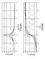
- FIG. 4A shows magnitude response characteristics for three different values of the damping factor ⁇ , while FIG. 4B shows the corresponding phase response characteristics.
- FIG. 5 shows a feedback loop for controlling a vibration frequency applied to the flow meter assembly.
- FIGS. 1-5 and the following description depict specific examples to teach those skilled in the art how to make and use the best mode of the invention. For the purpose of teaching inventive principles, some conventional aspects have been simplified or omitted. Those skilled in the art will appreciate variations from these examples that fall within the scope of the invention. Those skilled in the art will appreciate that the features described below can be combined in various ways to form multiple variations of the invention. As a result, the invention is not limited to the specific examples described below, but only by the claims and their equivalents.
- FIG. 1 illustrates a Coriolis flow meter 5 comprising a flow meter assembly 10 and meter electronics 20 .
- Meter electronics 20 is connected to meter assembly 10 via leads 100 to provide density, mass flow rate, volume flow rate, totalized mass flow, temperature, and other information over path 26 .
- Flow meter assembly 10 includes a pair of flanges 101 and 101 ′, manifolds 102 and 102 ′, driver 104 , pick-off sensors 105 - 105 ′, and flow conduits 103 A and 103 B.
- Driver 104 and pick-off sensors 105 and 105 ′ are connected to flow conduits 103 A and 103 B.
- Flanges 101 and 101 ′ are affixed to manifolds 102 and 102 ′.
- Manifolds 102 and 102 ′ are affixed to opposite ends of spacer 106 .
- Spacer 106 maintains the spacing between manifolds 102 and 102 ′ to prevent undesired vibrations in flow conduits 103 A and 103 B.
- flow meter assembly 10 When flow meter assembly 10 is inserted into a pipeline system (not shown) which carries the material being measured, material enters flow meter assembly 10 through flange 101 , passes through inlet manifold 102 where the total amount of material is directed to enter flow conduits 103 A and 103 B, flows through flow conduits 103 A and 103 B and back into outlet manifold 102 ′ where it exits meter assembly 10 through flange 101 ′.
- Flow conduits 103 A and 103 B are selected and appropriately mounted to inlet manifold 102 and outlet manifold 102 ′ so as to have substantially the same mass distribution, moments of inertia, and elastic modules about bending axes W-W and W′-W′ respectively.
- the flow conduits extend outwardly from the manifolds in an essentially parallel fashion.
- Flow conduits 103 A-B are driven by driver 104 in opposite directions about their respective bending axes W and W′ and at what is termed the first out-of-phase bending mode of the flow meter.
- Driver 104 may comprise one of many well known arrangements, such as a magnet mounted to flow conduit 103 A and an opposing coil mounted to flow conduit 103 B. An alternating current is passed through the opposing coil to cause both conduits to oscillate.
- a suitable drive signal is applied by meter electronics 20 , via lead 110 to driver 104 .
- Meter electronics 20 transmits sensor signals on leads 111 and 111 ′, respectively.
- Meter electronics 20 produces a drive signal on lead 110 which causes driver 104 to oscillate flow conduits 103 A and 103 B.
- Meter electronics 20 processes left and right velocity signals from pick-off sensors 105 and 105 ′ in order to compute a mass flow rate.
- Path 26 provides an input and an output means that allows meter electronics 20 to interface with an operator.
- FIG. 1 is provided merely as an example of the operation of a Coriolis flow meter and is not intended to limit the teaching of the present invention.
- FIG. 2 shows meter electronics 20 according to an embodiment of the invention.
- the meter electronics 20 includes a communication interface 201 , a processing system 202 , and a storage system 203 .
- the processing system 202 is coupled to the communication interface 201 .
- the communication interface 201 enables communications between the meter electronics 20 and external devices.
- the communication interface 201 enables transmission of computed flow characteristics to an external device via the path 26 .
- the external devices can include the flow meter assembly 10 (via the leads 100 of FIG. 1 ), a monitoring device or devices (via the path 26 of FIG. 1 ), or any manner of user interface or communication device.
- the communication interface 201 enables the receipt of flow measurements from the flow meter assembly 10 over the leads 100 .
- the communication interface 201 can be capable of any manner of electronic, optical, or wireless communication, for example.
- the interface 26 can enable communication over telephone systems and/or digital data networks. Consequently, the meter electronics 20 can communicate with remote flow meters, remote processing/monitoring devices, remote memory media, and/or remote users.
- the processing system 202 conducts operations of the meter electronics 20 and processes flow measurements from the flow meter assembly 10 .
- the processing system 202 executes a processing routine 210 and processes the flow measurements in order to produce one or more flow characteristics.
- the processing system 202 can comprise a general purpose computer, a microprocessing system, a logic circuit, or some other general purpose or customized processing device.
- the processing system 202 can be distributed among multiple processing devices.
- the processing system 202 can include any manner of integral or independent electronic storage medium, such as the storage system 203 .
- the storage system 203 can comprise an independent electronic storage medium in communication with the processing system 202 .
- the storage system 203 can store flow meter parameters and data, software routines, constant values, and variable values.
- the storage system 203 includes the processing routine 210 that is executed by the processing system 202 .
- the storage system 203 stores variables used to operate the flow meter assembly 10 .
- the storage system 203 in one embodiment stores variables such as a first vibration frequency 211 , at least a second vibration frequency 212 , a first vibrational response 213 , a second vibrational response 214 , and a sweep time period 215 .
- the storage system 203 stores one or more flow characteristics obtained from the flow measurements.
- the storage system 203 in one embodiment stores flow characteristics such as a mass flow rate 220 , a density 221 , a kinematic viscosity 222 , a dynamic viscosity 223 , a shear rate 224 , a Reynolds number 225 , a velocity of sound (VOS) 226 , and a damping factor (or quality factor Q) 227 . It should be understood that other flow characteristics can also be determined and recorded, such as temperature and/or pressure, for example.
- the mass flow rate 220 is a measurement of the mass flow through the flow meter assembly 10 .
- the density 221 is the density of the flow material in the flow meter assembly 10 .
- Viscosity of a fluid can be defined as a resistance of the fluid to shear or flow, and is a measure of the adhesive/cohesive properties of the fluid. This resistance is caused by intermolecular fiction exerted when a first fluid layer attempts to slide past another fluid layer. A measurement of the viscous property of a fluid is desirable in order to properly design and operate equipment for pumping, measuring, or otherwise handling a fluid.
- the kinematic viscosity 222 can be defined as a ratio of dynamic viscosity to the density.
- the kinematic viscosity 222 can be calculated from the dynamic viscosity 223 and the density 221 .
- the dynamic viscosity 223 can be defined as a tangential force per unit area required to move one horizontal plane with respect to the other at a unit velocity when maintained a unit distance apart by the fluid.
- the shear rate 224 can be defined as the rate of change of velocity at which one layer of fluid passes over another fluid layer.
- the Reynolds number 225 can be defined as a measure of the importance of inertia to viscosity effects. At high Reynolds numbers, a flow may become turbulent, exhibiting qualitatively different behavior than the same liquid at a low Reynolds number.
- the VOS 226 is the speed of sound in the flow medium.
- the VOS 226 can change with changes in the flow medium, can change with changes in density in the flow medium, or can change with changes in the composition of the flow medium, for example.
- the damping factor 227 can be defined as a measure of how damped the vibration is by the flow medium. Alternatively, the damping factor 227 can be defined as a measure of the viscosity of the flow medium.
- the processing system 202 executes the processing routine 210 in order to determine the one or more flow characteristics.
- the processing routine 210 when executed by the processing system 202 , configures the processing system 202 to vibrate one or more flow conduits 103 of the flow meter 5 with the first vibration frequency 211 , measure the first vibrational response 213 of the one or more flow conduits 103 , with the first vibrational response 213 being generated in response to the first vibration frequency 211 , vibrate the one or more flow conduits 103 with at least a second vibration frequency 212 , measure a second vibrational response 214 , with the second vibrational response 214 being generated in response to the second vibration frequency 212 , and determine at least the mass flow rate 220 and a viscosity of the flow medium using the first vibrational response 213 and the second vibrational response 214 (see FIG. 3 ).
- the first vibration frequency 211 and the second vibration frequency 212 can comprise any desired frequencies.
- the first vibration frequency 211 and the second vibration frequency 212 are substantially equally spaced above and below a fundamental frequency of the flow meter assembly 10 .
- other frequencies can be employed, depending on the flow medium and the ambient environment.
- the processing routine 210 can jump between the first vibration frequency 211 and the second vibration frequency 212 .
- the processing routine 210 can substantially simultaneously vibrate the one or more flow conduits 103 with the first vibration frequency and the second vibration frequency.
- the processing routine 210 can sweep the vibration of the driver 104 between the first vibration frequency 211 and the second vibration frequency 212 , wherein the actual drive frequency is stepped between the two frequencies according to the sweep time period 215 .
- FIG. 3 is a flowchart 300 of a method for determining flow characteristics in a Coriolis flow meter 5 according to an embodiment of the invention.
- the flow tube apparatus 10 is vibrated with the first vibration frequency 211 and in a first out-of-phase bending mode by the driver 104 .
- the first vibration frequency 211 can be a fundamental vibration frequency of the flow meter assembly 10 , or can be a frequency above or below the fundamental frequency.
- the first vibrational response 213 is measured.
- the measurement comprises receiving signals from the pick-offs 105 and using the pick-off signals to determine the phase difference between the two pick-offs 105 .
- the first vibrational response 213 is generated by the flow meter assembly 10 in response to the first vibration frequency 211 generated by the driver 104 .
- the flow meter assembly 10 is vibrated with a second vibration frequency 212 and in the first out-of-phase bending mode by the driver 104 .
- the second vibration frequency 212 can be any frequency that is not the first vibration frequency 211 .
- the first and second vibration frequencies 211 and 212 are substantially equally spaced above and below a fundamental frequency of the flow meter assembly 10 .
- the first and second vibration frequencies 211 and 212 can comprise any desired frequencies.
- a second vibrational response 214 is measured.
- the second vibrational response 214 is generated by the flow meter assembly 10 in response to the second vibration frequency 212 generated by the driver 104 .
- the mass flow rate and other flow characteristics are determined by the meter electronics 20 from the first and second vibrational responses 213 and 214 .
- the meter electronics 20 can determine many flow characteristics.
- the flow characteristics can include the density 221 , the kinematic viscosity 222 , the dynamic viscosity 223 , the shear rate 224 , the Reynolds number 225 , the VOS 226 , and the damping factor 227 of the flow material in the flow meter assembly 10 .
- x is an instantaneous flow tube displacement and the terms dx/dt and dx 2 /dt 2 are first and second order derivatives of the displacement, respectively.
- FIG. 4A shows magnitude response characteristic curves for three different values of the damping factor ⁇
- FIG. 4B shows the three corresponding phase response characteristic curves.
- the dynamic viscosity (v) of a flow medium passing through a Coriolis mass flow meter will directly alter the structure's quality factor Q.
- a first method measures the quality factor Q directly as defined by equation (5) by measuring the peak amplitude
- the flow meter assembly 10 can be driven open loop through a continuum of drive frequencies encompassing ⁇ 0 . This is done while maintaining the drive power constant, as a means of normalization.
- the difficulty with this approach is that it requires some type of absolute amplitude response calibration, which can be noisy and inaccurate and does not account for the variability of pickoff efficiency.
- a second method drives the flow conduit or conduits to their nominal displacement amplitude and periodically disengages the driving force while monitoring the oscillation's amplitude decay.
- the time taken for the amplitude to decrease to 0.707 of its peak value will provide an alternate measure of the quality factor Q.
- the difficulties encountered with this method stem from the discontinuous nature of the driving function, which will instantaneously and periodically perturb the quality of the mass flow rate measurement.
- a third method measures the quality factor Q of the flow meter assembly 10 by driving the flow meter assembly 10 successively at the half power points ⁇ 1 and ⁇ 2 and at the point of maximum response ⁇ 0 .
- This is an attractive approach because the quality factor is totally dependent on the mechanical properties of the resonator, and is not dependent on the efficiency of the driver 104 or on the efficiency of the pick-offs 105 .
- the difficulty with this approach is that when the flow meter assembly 10 is switched from one frequency to another (such as from ⁇ 1 to ⁇ 0 ), the flow meter assembly 10 will be disrupted and will need time to settle back into its stable regime. During this settling period, all process information (viscosity, density, and mass flow rate) can be lost or the measurement quality can be seriously degraded.
- the invention provides a substantially continuous and uncompromised measurement of at least mass flow rate, density, and viscosity.
- FIG. 5 shows a feedback loop for controlling a vibration frequency applied to the flow meter assembly 10 .
- the feedback loop can include the Coriolis sensor 500 (i.e., the flow meter 5 ), a phase shifter 501 , a digital-to-analog (D/A) converter 502 , an analog-to-digital (A/D) converter 503 , and a phase sensor 504 .
- the phase shifter 501 generates a digital drive signal that is converted to an analog drive signal by the D/A 502 and provided to the Coriolis sensor 500 .
- the pickoff signal output is provided to the A/D 503 , which digitized the analog pickoff signal and provides it to the phase shifter 501 .
- the phase sensor 504 compares the input (drive) phase to the output (sensor) phase, and generates a phase difference signal to the phase shifter 501 .
- the phase shifter 501 can control the phase shift and the frequency of the drive signal provided to the Coriolis sensor 500 .
- the invention controls the phase between the sensor's input and output so as to continuously cycle the closed-loop resonance between first and second vibration frequencies ⁇ 1 and ⁇ 2 while maintaining the system under closed-loop control.
- phase control can be digitally implemented using standard phase-locked loop techniques.
- the closed-loop control can be performed by an appropriately programmed Digital Signal Processor (DSP).
- DSP Digital Signal Processor
- other feedback or loop control techniques can be employed and are within the scope of the description and claims.
- the system closed-loop oscillating frequency will track continuously as predicted by the phase curve shown in FIG. 4B . Therefore, for every period of time T ⁇ , all relevant variables ( ⁇ 0 , ⁇ 1 , ⁇ 2 , and mass flow rate) can be measured by tracking the relative amplitude response throughout the continuum of operating points ⁇ E [ ⁇ 1 , ⁇ 2 ], with no need for absolute calibration of the amplitude response.
- the density ⁇ can be determined in various ways. For example, in one embodiment the density ⁇ can be determined by periodically updating the density output each time the phase passes through the density calibration phase point ⁇ cal . In another embodiment, the density ⁇ is dynamically determined by applying a frequency correction factor, wherein the frequency correction factor is dependent on the actual phase and on the viscosity of the product.
- the shear rate 224 can be determined by utilizing the mass flow rate 220 through the flow meter assembly 10 and from the natural resonant frequency of the flow meter assembly 10 . Consequently, by changing the flow rate and/or by changing the resonant frequency of the flow meter 5 by operating in a different mode of vibration, the shear rate 224 can be modified. This capability leads to the ability to profile non-Newtonian or liquid products substantially instantaneously. Fluids for which the shearing stress is linearly related to the rate of shearing strain are designated as being Newtonian fluids. Newtonian materials are referred to as true liquids, since their viscosity or consistency is not affected by shear, such as agitation or pumping at a constant temperature. Fortunately, most common fluids, both liquids and gases, are Newtonian, including water and oils.
- the Reynolds number R e 225 for the flow medium can be determined from the three prime measurements that are simultaneously measured by the flow meter assembly 10 , i.e., the Reynolds number R e 225 can be determined from the mass flow rate 220 , the density 221 , and from the dynamic viscosity 223 .
- the vibrational responses generated by the Coriolis flow meter 5 can additionally be used for other purposes.
- the two or more vibrational responses can be used to determine a flexural stiffness of the flow meter assembly 10 .
- the flexural stiffness can be used in order to correct a Flow Calibration Factor (FCF) based on a stiffness change.
- FCF Flow Calibration Factor
- Flexural stiffness is the static spring rate derived from flexing the flow tube with a known force pattern and measuring the flow tube displacement. Any force pattern could be used to measure flexural stiffness, as long as it is invariant.
- the flexural stiffness for a clamped beam is as follows:
- FCF flow calibration factor
- FCF C ⁇ [ EI L 3 ] ( 14 ) where C is a constant determined by mode shape and pick-off locations.
- Flow tube flexural stiffness can also be determined by estimating points on a tube frequency response function (FRF) at given frequencies. These points are then used to fit a single degree of freedom model to the data and determine the DC (e.g. zero crossing) point on the FRF.
- FRF tube frequency response function
- a flow calibration factor can be validated using a multiple frequency estimation process.
- Multiple frequency estimation begins by identifying constants m 1 , c 1 , k 1 , ⁇ 1 , ⁇ 1 , and A 1 using any time domain or frequency domain system identification method.
- a curve fitting procedure is used to fit a rational continuous time transfer function model to the complex frequency response vector H at the set of frequencies in vector W (in radians/second). The number and location (in frequency) of the FRF data points does affect the quality of the fit.
- a good fit is achieved using as few as 2 frequency response data points.
- the derived model is of the form:
- H ⁇ ( s ) b ⁇ ( 1 ) ⁇ s N b + b ⁇ ( 2 ) ⁇ s ( N b - 1 ) + ... + b ⁇ ( N b + 1 ) s N b + a ⁇ ( 2 ) ⁇ s ( N a - 1 ) + ... + a ⁇ ( N a + 1 ) ( 15 )
- the driver pickoff mobility (velocity) frequency response data is converted to the receptance (displacement) form.
- the measured mobility frequency response data H must be multiplied by 1/(i ⁇ ).
- the measured mobility drive loop frequency response H should be from drive coil current (proportional to force) to pickoff voltage (proportional to velocity).
- the modal parameters of interest are extracted from the transfer function model as follows:
- the two or more vibrational responses can also be used to detect and differentiate flow meter structure changes, such as erosion, corrosion, and coating of the flow tube.
- the Coriolis flow meter 5 is vibrated at its resonant frequency so as to enable flow meter 5 to measure mass and density.
- FCF is the flow calibration factor
- ⁇ t is the time delay
- ⁇ t 0 is the time delay at zero flow.
- the FCF term is proportional to the stiffness of the flow meter. Stiffness is the predominate parameter that affects the flow meter's performance. If the stiffness of the flow meter changes, then the meter's FCF will change. A change in the flow meters performance can be caused by corrosion, erosion, and coating, for example.
- G is a geometric constant associated with a particular sensor
- E Young's Modulus
- I is the moment of inertia.
- the area moment of inertia, I changes when the meter's flow tube changes. For example, if the tube corrodes reducing the wall thickness, the area moment of inertia is decreased.
- the invention includes a process for detecting and differentiating flow meter structure changes from indicated changes in flow rate.
- the process starts with the determination of mass flow rate, , using multiple modes and the following equation:
- the mass flow reading for each mode is compared.
- the resulting mass flow rate must be the same for each mode. If the mass flow readings are equal, the comparison generates a “proper operation” signal and the process restarts.
- the “proper operation” signal can be in the form of a visible or audible signal to a user, for example.
- an error signal When a deviation occurs between the mass flow rates, which are outside of acceptable limits, an error signal is generated.
- the error signal can cause various actions to occur. For instance, the error signal may cause the process to be shut down or may signal a visible or audible warning to an operator who then takes appropriate action.
- k is the stiffness of an assembly
- m is the mass of the assembly
- f is the frequency of oscillation
- ⁇ is the period of oscillation
- Equation (22) is the solution of the equation of motion for a single degree-of-freedom system.
- a Coriolis flow meter at zero flow is represented by an expansion of equation (22), yielding:
- E Young's modulus
- I is the cross-sectional moment of inertia
- G p is a geometric constant
- A is the cross-sectional area
- t represents the material of the flow tube(s).
- the invention includes a process for detecting and differentiating flow meter structure changes from changes in indicated density.
- the process starts with the determination of density, ⁇ , using multiple modes. Multiple modes can be excited either from flow noise or forced vibration.
- the density readings for each mode are compared.
- the resulting density reading must be the same for each mode. If the density readings are equal, the process generates a “proper operation” signal and the process restarts.
- the “proper operation” signal can be in the form of a visible or audible signal to a user.
- an error signal When a deviation occurs between the density readings, which are outside of acceptable limits, an error signal is generated.
- the error signal can cause various actions to occur. For instance, the error signal may cause the process to be shut down or may signal a visible or audible warning to an operator who then takes appropriate action.
- the Coriolis flow meter and method according to the invention can be employed according to any of the embodiments in order to provide several advantages, if desired.
- the invention provides a flow meter that is capable of measuring various flow characteristics.
- the invention measures the flow characteristics using at least first and second vibration frequencies to excite the flow meter assembly.
- the invention advantageously operates a Coriolis flow meter to provide additional measurements of dynamic viscosity, kinematic viscosity, and density without compromising the mass flow measurement performance of the flow meter.
- the invention can additionally provide shear rate, Reynolds number, VOS, and damping factor values.
- the invention can be used for ship fuel oil blending, wherein kerosene is blended with fuel oil to a given kinematic viscosity specification.
- the resulting blend can be concurrently metered onto a ship.
- the mass flow rate, the density, and the viscosity measurements are required.
- the invention can be used for lube oil drum filling.
- the interface between the different lube oil products must be accurately detected in order to prevent contamination.
- the interface is detected through a change in product viscosity using the viscosity measurement provided by the invention.
- the mass flow output is used to accurately batch fill the drums using the mass flow rate measurement provided by the invention.
- the invention can be used for receiving high fructose corn syrup (HFCS) solutions, such as HFCS-55, for example.
- HFCS high fructose corn syrup
- each solution will have a specific density (in Brix) and viscosity quality specification.
- Brix has been defined as a measure of the percentage of solids in a plant juice or alternatively as a measure of percentage of sucrose (sugar).
- sucrose sucrose
Abstract
Description
dx 2 /dt 2+2ζdx/dt(t)+ω2 n x(t)=ω2 n A cos(ωt) (1)
where the right hand side represents the normalized oscillatory forcing function and ζ is the damping factor. Here, x is an instantaneous flow tube displacement and the terms dx/dt and dx2/dt2 are first and second order derivatives of the displacement, respectively.
G(ω)=1/(1−(ω/ωn)2 +j2ζω/ωn) (2)
with a magnitude response of:
|G(ω)|2=1/([1−(ω/ωn)2]2+(2ζω/ωn)2) (3)
and with a phase response φ of:
φ(ω)=tan−12ζω/ωn/(1−(ω/ωn)2) (4)
Q=|G(ω)|max (5)
where the quality factor Q is equivalent to the damping factor ζ.
Q≈½ζ≈ωn/(ω2−ω1) (6)
where ω1 and ω2 are the half power points at which an amplitude response for the
Δω=ω2−ω1 (7)
is also known as the 3 dB bandwidth of the system. Note that generally the point of maximum response ω0 is given by:
ω0=ωn√(1−2ζ2) (8)
indicating that the maximum response ω0 occurs at a frequency lower than the undamped natural frequency ωn.
Q=K v/√(v) (9)
where Kv is a proportionality constant that is divided by the square root of the viscosity v. This suggests that a method that enables the
φ(t)=φ0+Δφ sin(2πt/T φ) (10)
with the phase modulation index Δφ and the modulation period Tφ being on the order of several seconds in one embodiment. With such a slowly varying phase variation, the system closed-loop oscillating frequency will track continuously as predicted by the phase curve shown in
where:
Kflex=CPCGCS[EI] (12)
where:
So the flow calibration factor (FCF) for the straight tube is:
where C is a constant determined by mode shape and pick-off locations.
where a(1)=1. The modal parameters of interest are extracted from the transfer function model as follows:
The physical parameters can then be calculated using the following equations:
m 1=1/A 1
c 1=2ζ1ω1 /A 1
k 1=ω1 2 /A 1 (18)
Where:
Where:
Where:
Where:
ρf =C 1τ2 −C 2 (24)
Where:
The geometric constant, Gp, accounts for geometric parameters such as tube length and shape. The constants, C1 and C2, are determined as part of the normal calibration process at zero flow on two different fluids.
Claims (37)
Priority Applications (1)
| Application Number | Priority Date | Filing Date | Title |
|---|---|---|---|
| US11/908,385 US7716995B2 (en) | 2005-03-29 | 2005-03-29 | Coriolis flow meter and method for determining flow characteristics |
Applications Claiming Priority (2)
| Application Number | Priority Date | Filing Date | Title |
|---|---|---|---|
| US11/908,385 US7716995B2 (en) | 2005-03-29 | 2005-03-29 | Coriolis flow meter and method for determining flow characteristics |
| PCT/US2005/010367 WO2006104485A1 (en) | 2005-03-29 | 2005-03-29 | Coriolis flow meter and method for determining flow characteristics |
Publications (2)
| Publication Number | Publication Date |
|---|---|
| US20080184813A1 US20080184813A1 (en) | 2008-08-07 |
| US7716995B2 true US7716995B2 (en) | 2010-05-18 |
Family
ID=35456918
Family Applications (1)
| Application Number | Title | Priority Date | Filing Date |
|---|---|---|---|
| US11/908,385 Active 2026-01-18 US7716995B2 (en) | 2005-03-29 | 2005-03-29 | Coriolis flow meter and method for determining flow characteristics |
Country Status (12)
| Country | Link |
|---|---|
| US (1) | US7716995B2 (en) |
| EP (1) | EP1872095A1 (en) |
| JP (1) | JP4831784B2 (en) |
| KR (3) | KR101484074B1 (en) |
| CN (1) | CN100491933C (en) |
| AR (1) | AR052721A1 (en) |
| AU (1) | AU2005330018B2 (en) |
| BR (1) | BRPI0520150B1 (en) |
| CA (1) | CA2602863C (en) |
| HK (1) | HK1114900A1 (en) |
| MX (1) | MX2007011594A (en) |
| WO (1) | WO2006104485A1 (en) |
Cited By (13)
| Publication number | Priority date | Publication date | Assignee | Title |
|---|---|---|---|---|
| US20070017274A1 (en) * | 2003-10-22 | 2007-01-25 | Wheeler Matthew G | Diagnostic apparatus and methods for a coriolis flow meter |
| US20100089174A1 (en) * | 2007-03-14 | 2010-04-15 | Micro Motion, Inc. | Vibratory flow meter and method for determining viscosity in a flow material |
| US20100281999A1 (en) * | 2009-05-08 | 2010-11-11 | Endress + Hauser Flowtec | Method for determining measuring tube wall thickness of a coriolis, flow measuring device |
| US20110178738A1 (en) * | 2005-09-19 | 2011-07-21 | Micro Motion, Inc. | Meter electronics and methods for verification diagnostics for a flow meter |
| US20110264385A1 (en) * | 2008-11-13 | 2011-10-27 | Joel Weinstein | Method and apparatus for measuring a fluid parameter in a vibrating meter |
| WO2014084835A1 (en) | 2012-11-29 | 2014-06-05 | Micro Motion, Inc. | Detection of a change in the cross - sectional area of a fluid tube in a vibrating meter by determining a lateral mode stiffness |
| US8760658B2 (en) * | 2012-10-12 | 2014-06-24 | Perkinelmer Health Sciences, Inc. | Flow cell modules and liquid sample analyzers and methods including same |
| US20140190238A1 (en) * | 2011-07-13 | 2014-07-10 | Micro Motion, Inc. | Vibratory meter and method for determining resonant frequency |
| WO2015155044A1 (en) * | 2014-04-09 | 2015-10-15 | Eth Zurich | Method and device for multiple-frequency tracking of oscillating systems |
| US20170146380A1 (en) * | 2015-11-24 | 2017-05-25 | Malema Engineering Corporation | Integrated coriolis mass flow meters |
| US10436692B2 (en) * | 2014-12-19 | 2019-10-08 | Endress + Hauser Flowtec Ag | Measuring arrangement and method for measuring the density of flowable media |
| US10612954B2 (en) | 2013-06-14 | 2020-04-07 | Micro Motion, Inc. | Vibratory flowmeter and method for meter verification |
| US11619532B2 (en) | 2020-04-10 | 2023-04-04 | Malema Engineering Corporation | Replaceable, gamma sterilizable Coriolis flow sensors |
Families Citing this family (45)
| Publication number | Priority date | Publication date | Assignee | Title |
|---|---|---|---|---|
| WO2006104485A1 (en) * | 2005-03-29 | 2006-10-05 | Micro Motion, Inc. | Coriolis flow meter and method for determining flow characteristics |
| DE102006031198B4 (en) * | 2006-07-04 | 2012-01-26 | Krohne Ag | Method of operating a Coriolis mass flowmeter |
| DE102006039726B4 (en) * | 2006-08-24 | 2009-11-12 | Abb Ag | Method and device for determining the Q-factor in flowmeters |
| GB0725199D0 (en) | 2007-12-22 | 2008-01-30 | Precision Energy Services Inc | Measurement tool and method of use |
| WO2009134827A1 (en) * | 2008-05-01 | 2009-11-05 | Micro Motion, Inc. | Very high frequency vibratory flow meter |
| RU2454636C1 (en) * | 2008-06-05 | 2012-06-27 | Майкро Моушн, Инк. | Method and apparatus for maintaining vibration amplitude of flow tube in variable temperature interval |
| US8347735B2 (en) | 2008-06-05 | 2013-01-08 | Micro Motion, Inc. | Method and apparatus for maintaining flow meter tube amplitude over a variable temperature range |
| DE102008059920B4 (en) * | 2008-12-02 | 2016-07-14 | Krohne Meßtechnik GmbH & Co KG | Method for operating a resonance measuring system and related resonance measuring system |
| JP5542355B2 (en) * | 2009-03-24 | 2014-07-09 | トキコテクノ株式会社 | Vibration measuring device |
| US8831896B2 (en) | 2009-07-13 | 2014-09-09 | Micro Motion, Inc. | Meter electronics and fluid quantification method for a fluid being transferred |
| US9086308B2 (en) * | 2009-12-14 | 2015-07-21 | Siemens Aktiengesellschaft | Method for operating a coriolis mass flow rate meter and coriolis mass flow rate meter |
| US8671776B2 (en) * | 2009-12-31 | 2014-03-18 | Endress + Hauser Flowtec Ag | Measuring medium flow with a measuring transducer of the vibration type |
| JP4952820B2 (en) * | 2010-05-13 | 2012-06-13 | 横河電機株式会社 | Coriolis flow meter |
| DE102011012498A1 (en) * | 2010-11-19 | 2012-05-24 | Krohne Messtechnik Gmbh | Method for operating resonant measuring system, particularly in form of coriolis mass flow meter or in form of density measuring device, involves determining measured value for amplitude-dependent state variable of multi-phase medium |
| AU2012388249B2 (en) * | 2012-08-21 | 2016-05-12 | Micro Motion, Inc. | Coriolis flowmeter and method with improved meter zero |
| DE102012017797B4 (en) * | 2012-09-10 | 2014-09-18 | Krohne Ag | Flowmeter |
| BR112015006800B1 (en) | 2012-09-27 | 2020-11-10 | Micro Motion, Inc. | meter electronics, and method of obtaining a fluid viscosity in flow at a predetermined reference temperature |
| EP2954317A4 (en) * | 2013-02-06 | 2016-10-12 | Ultimo Measurement Llc | Non-invasive method for measurement of physical properties of free flowing materials in vessels |
| KR102002126B1 (en) * | 2013-04-23 | 2019-07-19 | 마이크로 모우션, 인코포레이티드 | A method of generating a drive signal for a vibratory sensor |
| JP6478975B2 (en) | 2013-04-26 | 2019-03-06 | マイクロ モーション インコーポレイテッド | Vibration sensor and method of changing vibration with vibration sensor |
| KR101889831B1 (en) * | 2013-11-14 | 2018-08-21 | 마이크로 모우션, 인코포레이티드 | Coriolis direct wellhead measurement devices and methods |
| KR20160111502A (en) * | 2014-01-24 | 2016-09-26 | 마이크로 모우션, 인코포레이티드 | Vibratory flowmeter and methods and diagnostics for meter verification |
| AT515552B1 (en) * | 2014-05-28 | 2015-10-15 | Anton Paar Gmbh | Method and device for determining a density value |
| CN106461430B (en) | 2014-07-01 | 2020-10-16 | 高准公司 | Fluid momentum detection method and related device |
| AT516420B1 (en) * | 2014-10-20 | 2016-11-15 | Anton Paar Gmbh | Method and device for determining the density of a fluid |
| CA2963400C (en) * | 2014-10-21 | 2022-04-12 | Micro Motion, Inc. | Apparatus for applying a variable zero algorithm in a vibrating flowmeter and related method |
| US9689736B2 (en) * | 2014-10-31 | 2017-06-27 | Invensys Systems, Inc. | Method to provide a quality measure for meter verification results |
| CN107110824B (en) * | 2014-12-19 | 2020-06-26 | 高准公司 | Determining a vibration response parameter of a vibratory element |
| JP6080880B2 (en) * | 2015-03-03 | 2017-02-15 | マイクロ モーション インコーポレイテッド | Method and apparatus for measuring fluid parameters with a vibrometer |
| EP3265760A1 (en) * | 2015-03-04 | 2018-01-10 | Micro Motion, Inc. | Flowmeter measurement confidence determination devices and methods |
| DE102015110741A1 (en) * | 2015-07-03 | 2017-01-05 | Schmidt & Haensch Gmbh & Co. | Method and device for determining the density of liquids |
| JP6701330B2 (en) * | 2015-10-21 | 2020-05-27 | マイクロ モーション インコーポレイテッド | Transducer calibration in situ |
| DE102015122225A1 (en) * | 2015-12-18 | 2017-06-22 | Endress + Hauser Flowtec Ag | Method for Reynolds number correction of a flow measurement of a Coriolis flowmeter |
| CN106706468A (en) * | 2016-12-30 | 2017-05-24 | 青岛澳威流体计量有限公司 | Vibrating tube type on-line densimeter |
| EP3645983B1 (en) * | 2017-06-27 | 2022-08-24 | Micro Motion, Inc. | Force compensation for a vibrating flowmeter and related method |
| DE102017116515A1 (en) * | 2017-07-21 | 2019-01-24 | Endress + Hauser Flowtec Ag | Device for measuring viscosities |
| EP3673241B1 (en) * | 2017-08-23 | 2022-12-14 | Micro Motion, Inc. | Vibratory flow meter with multichannel flow tube |
| CN109425398B (en) * | 2017-08-25 | 2023-10-27 | 罗凡 | Fluid flow tube, sensor assembly, and coriolis mass flowmeter |
| DE102018101923A1 (en) * | 2017-11-02 | 2019-05-02 | Endress + Hauser Flowtec Ag | Method for detecting deposit formation in a measuring tube and measuring device for carrying out the method |
| DE102017129036A1 (en) * | 2017-12-06 | 2019-06-06 | Endress+Hauser Flowtec Ag | Method for determining the viscosity of a medium by means of a Coriolis mass flow meter and Coriolis mass flow meter for carrying out the method |
| US10598531B2 (en) * | 2018-04-23 | 2020-03-24 | General Electric Company | Coriolis flow meter with multiple actuators arranged on a flow tube and driven in different planes |
| SG11202101264SA (en) | 2018-08-13 | 2021-03-30 | Micro Motion Inc | Determining a decay characteristic of a meter assembly |
| RU198668U1 (en) * | 2020-05-08 | 2020-07-21 | Николай Васильевич Сизов | High Pressure In-Line Coriolis Flow Meter |
| WO2024058768A1 (en) * | 2022-09-12 | 2024-03-21 | Micro Motion, Inc. | Determining a viscosity of a fluid |
| CN117499620A (en) * | 2023-12-13 | 2024-02-02 | 荣耀终端有限公司 | Motor test system and motor test method |
Citations (21)
| Publication number | Priority date | Publication date | Assignee | Title |
|---|---|---|---|---|
| US4331025A (en) | 1980-10-14 | 1982-05-25 | Mapco, Inc. | Methods of measuring fluid viscosity and flow rate |
| US4524610A (en) | 1983-09-02 | 1985-06-25 | National Metal And Refining Company, Ltd. | In-line vibratory viscometer-densitometer |
| US4930351A (en) * | 1988-03-24 | 1990-06-05 | Wjm Corporation | Vibratory linear acceleration and angular rate sensing system |
| US5069074A (en) * | 1987-07-22 | 1991-12-03 | Exac Corporation | Apparatus and method for measuring the mass flow rate of material flowing through at least one vibrating conduit |
| US5253533A (en) | 1990-07-28 | 1993-10-19 | Krohne Messtechnik Massametron Gmbh & Co. Kg | Mass flow meter |
| US5285686A (en) * | 1991-06-25 | 1994-02-15 | Sundstrand Data Control, Inc. | Coliolis rate sensor using tunnel-effect displacement sensor |
| US5359881A (en) | 1992-03-20 | 1994-11-01 | Micro Motion, Incorporated | Viscometer for sanitary applications |
| US5576500A (en) | 1991-02-05 | 1996-11-19 | Direct Measurement Corporation | Coriolis mass flow rate meter having means for modifying angular velocity gradient positioned within a conduit |
| US5661232A (en) | 1996-03-06 | 1997-08-26 | Micro Motion, Inc. | Coriolis viscometer using parallel connected Coriolis mass flowmeters |
| US5734112A (en) | 1996-08-14 | 1998-03-31 | Micro Motion, Inc. | Method and apparatus for measuring pressure in a coriolis mass flowmeter |
| US5861561A (en) | 1996-01-17 | 1999-01-19 | Micro Motion, Inc. | Bypass type coriolis effect flowmeter |
| US5877409A (en) | 1997-06-06 | 1999-03-02 | Mobil Oil Corporation | Method and system for determining viscosity index |
| US5929344A (en) | 1997-07-28 | 1999-07-27 | Micro Motion, Inc. | Circuitry for reducing the number of conductors for multiple resistive sensors on a coriolis effect mass flowmeter |
| US6006609A (en) | 1996-12-11 | 1999-12-28 | Endress + Hauser Flowtec Ag | Coriolis mass flow/density sensor with a single straight measuring tube |
| US6092429A (en) | 1997-12-04 | 2000-07-25 | Micro Motion, Inc. | Driver for oscillating a vibrating conduit |
| US6347293B1 (en) | 1999-07-09 | 2002-02-12 | Micro Motion, Inc. | Self-characterizing vibrating conduit parameter sensors and methods of operation therefor |
| RU2000104841A (en) | 1997-07-28 | 2002-02-27 | Майкро Моушн, Инк. | MANY RESISTIVE SENSORS FOR MASS FLOW METER WITH CORIOLIS EFFECT |
| US6502466B1 (en) | 1999-06-29 | 2003-01-07 | Direct Measurement Corporation | System and method for fluid compressibility compensation in a Coriolis mass flow meter |
| US6651513B2 (en) | 2000-04-27 | 2003-11-25 | Endress + Hauser Flowtec Ag | Vibration meter and method of measuring a viscosity of a fluid |
| DE10235322A1 (en) | 2002-08-01 | 2004-02-12 | Endress + Hauser Flowtec Ag, Reinach | Vibration or Coriolis fluid mass flowmeter for measurement of mass flow, and or viscosity, has a single straight measurement pipe and an additional vibrator for generation of a torsional vibration and therefore fluid shear forces |
| US20080184813A1 (en) * | 2005-03-29 | 2008-08-07 | Micro Motion, Inc. | Coriolis Flow Meter and Method for Determining Flow Characteristics |
Family Cites Families (9)
| Publication number | Priority date | Publication date | Assignee | Title |
|---|---|---|---|---|
| EP0749570B1 (en) * | 1994-03-07 | 1998-09-16 | Joseph Goodbread | Method and device for measuring the characteristics of an oscillating system |
| JP3058074B2 (en) * | 1995-08-29 | 2000-07-04 | 富士電機株式会社 | Vibration type measuring instrument |
| US6378364B1 (en) * | 2000-01-13 | 2002-04-30 | Halliburton Energy Services, Inc. | Downhole densitometer |
| EP1253408A1 (en) * | 2001-04-24 | 2002-10-30 | Endress + Hauser Flowtec AG | Vibration type measuring transducer |
| JP4078848B2 (en) * | 2002-02-26 | 2008-04-23 | Kddi株式会社 | Adaptive coding method and transmitter using space-time block code |
| US7197084B2 (en) * | 2002-03-27 | 2007-03-27 | Qualcomm Incorporated | Precoding for a multipath channel in a MIMO system |
| US7522673B2 (en) * | 2002-04-22 | 2009-04-21 | Regents Of The University Of Minnesota | Space-time coding using estimated channel information |
| US7242724B2 (en) * | 2003-07-16 | 2007-07-10 | Lucent Technologies Inc. | Method and apparatus for transmitting signals in a multi-antenna mobile communications system that compensates for channel variations |
| KR20050015731A (en) * | 2003-08-07 | 2005-02-21 | 삼성전자주식회사 | Method and apparatus for deciding shuffling pattern in double space-time transmit diversity system using minimum signal to noise ratio |
-
2005
- 2005-03-29 WO PCT/US2005/010367 patent/WO2006104485A1/en active Application Filing
- 2005-03-29 US US11/908,385 patent/US7716995B2/en active Active
- 2005-03-29 JP JP2008503998A patent/JP4831784B2/en active Active
- 2005-03-29 KR KR1020137008129A patent/KR101484074B1/en active IP Right Grant
- 2005-03-29 CA CA2602863A patent/CA2602863C/en active Active
- 2005-03-29 AU AU2005330018A patent/AU2005330018B2/en active Active
- 2005-03-29 EP EP05730272A patent/EP1872095A1/en not_active Ceased
- 2005-03-29 KR KR1020147011043A patent/KR20140063884A/en not_active Application Discontinuation
- 2005-03-29 KR KR1020107016355A patent/KR20100094593A/en active Application Filing
- 2005-03-29 CN CNB2005800493205A patent/CN100491933C/en active Active
- 2005-03-29 MX MX2007011594A patent/MX2007011594A/en active IP Right Grant
- 2005-03-29 BR BRPI0520150-0A patent/BRPI0520150B1/en active IP Right Grant
-
2006
- 2006-03-28 AR ARP060101198A patent/AR052721A1/en active IP Right Grant
-
2008
- 2008-09-08 HK HK08109978.9A patent/HK1114900A1/en unknown
Patent Citations (21)
| Publication number | Priority date | Publication date | Assignee | Title |
|---|---|---|---|---|
| US4331025A (en) | 1980-10-14 | 1982-05-25 | Mapco, Inc. | Methods of measuring fluid viscosity and flow rate |
| US4524610A (en) | 1983-09-02 | 1985-06-25 | National Metal And Refining Company, Ltd. | In-line vibratory viscometer-densitometer |
| US5069074A (en) * | 1987-07-22 | 1991-12-03 | Exac Corporation | Apparatus and method for measuring the mass flow rate of material flowing through at least one vibrating conduit |
| US4930351A (en) * | 1988-03-24 | 1990-06-05 | Wjm Corporation | Vibratory linear acceleration and angular rate sensing system |
| US5253533A (en) | 1990-07-28 | 1993-10-19 | Krohne Messtechnik Massametron Gmbh & Co. Kg | Mass flow meter |
| US5576500A (en) | 1991-02-05 | 1996-11-19 | Direct Measurement Corporation | Coriolis mass flow rate meter having means for modifying angular velocity gradient positioned within a conduit |
| US5285686A (en) * | 1991-06-25 | 1994-02-15 | Sundstrand Data Control, Inc. | Coliolis rate sensor using tunnel-effect displacement sensor |
| US5359881A (en) | 1992-03-20 | 1994-11-01 | Micro Motion, Incorporated | Viscometer for sanitary applications |
| US5861561A (en) | 1996-01-17 | 1999-01-19 | Micro Motion, Inc. | Bypass type coriolis effect flowmeter |
| US5661232A (en) | 1996-03-06 | 1997-08-26 | Micro Motion, Inc. | Coriolis viscometer using parallel connected Coriolis mass flowmeters |
| US5734112A (en) | 1996-08-14 | 1998-03-31 | Micro Motion, Inc. | Method and apparatus for measuring pressure in a coriolis mass flowmeter |
| US6006609A (en) | 1996-12-11 | 1999-12-28 | Endress + Hauser Flowtec Ag | Coriolis mass flow/density sensor with a single straight measuring tube |
| US5877409A (en) | 1997-06-06 | 1999-03-02 | Mobil Oil Corporation | Method and system for determining viscosity index |
| US5929344A (en) | 1997-07-28 | 1999-07-27 | Micro Motion, Inc. | Circuitry for reducing the number of conductors for multiple resistive sensors on a coriolis effect mass flowmeter |
| RU2000104841A (en) | 1997-07-28 | 2002-02-27 | Майкро Моушн, Инк. | MANY RESISTIVE SENSORS FOR MASS FLOW METER WITH CORIOLIS EFFECT |
| US6092429A (en) | 1997-12-04 | 2000-07-25 | Micro Motion, Inc. | Driver for oscillating a vibrating conduit |
| US6502466B1 (en) | 1999-06-29 | 2003-01-07 | Direct Measurement Corporation | System and method for fluid compressibility compensation in a Coriolis mass flow meter |
| US6347293B1 (en) | 1999-07-09 | 2002-02-12 | Micro Motion, Inc. | Self-characterizing vibrating conduit parameter sensors and methods of operation therefor |
| US6651513B2 (en) | 2000-04-27 | 2003-11-25 | Endress + Hauser Flowtec Ag | Vibration meter and method of measuring a viscosity of a fluid |
| DE10235322A1 (en) | 2002-08-01 | 2004-02-12 | Endress + Hauser Flowtec Ag, Reinach | Vibration or Coriolis fluid mass flowmeter for measurement of mass flow, and or viscosity, has a single straight measurement pipe and an additional vibrator for generation of a torsional vibration and therefore fluid shear forces |
| US20080184813A1 (en) * | 2005-03-29 | 2008-08-07 | Micro Motion, Inc. | Coriolis Flow Meter and Method for Determining Flow Characteristics |
Cited By (25)
| Publication number | Priority date | Publication date | Assignee | Title |
|---|---|---|---|---|
| US20070017274A1 (en) * | 2003-10-22 | 2007-01-25 | Wheeler Matthew G | Diagnostic apparatus and methods for a coriolis flow meter |
| US7904268B2 (en) * | 2003-10-22 | 2011-03-08 | Micro Motion, Inc. | Diagnostic apparatus and methods for a coriolis flow meter |
| US20110178738A1 (en) * | 2005-09-19 | 2011-07-21 | Micro Motion, Inc. | Meter electronics and methods for verification diagnostics for a flow meter |
| US8280651B2 (en) * | 2005-09-19 | 2012-10-02 | Micro Motion, Inc. | Meter electronics and methods for verification diagnostics for a flow meter |
| US20100089174A1 (en) * | 2007-03-14 | 2010-04-15 | Micro Motion, Inc. | Vibratory flow meter and method for determining viscosity in a flow material |
| US8826745B2 (en) * | 2007-03-14 | 2014-09-09 | Micro Motion, Inc. | Vibratory flow meter and method for determining viscosity in a flow material |
| US20110264385A1 (en) * | 2008-11-13 | 2011-10-27 | Joel Weinstein | Method and apparatus for measuring a fluid parameter in a vibrating meter |
| US10466087B2 (en) * | 2008-11-13 | 2019-11-05 | Micron Motion, Inc. | Method and apparatus for measuring a fluid parameter in a vibrating meter |
| US20100281999A1 (en) * | 2009-05-08 | 2010-11-11 | Endress + Hauser Flowtec | Method for determining measuring tube wall thickness of a coriolis, flow measuring device |
| US8515691B2 (en) * | 2009-05-08 | 2013-08-20 | Endress + Hauser Flowtec Ag | Method for determining measuring tube wall thickness of a coriolis, flow measuring device |
| US9395236B2 (en) * | 2011-07-13 | 2016-07-19 | Micro Motion, Inc. | Vibratory meter and method for determining resonant frequency |
| US20140190238A1 (en) * | 2011-07-13 | 2014-07-10 | Micro Motion, Inc. | Vibratory meter and method for determining resonant frequency |
| US9091629B2 (en) | 2012-10-12 | 2015-07-28 | Perkinelmer Health Sciences, Inc. | Flow cell modules and liquid sample analyzers and methods including same |
| US9228934B2 (en) | 2012-10-12 | 2016-01-05 | PerkinsElmer Health Sciences, Inc. | Flow cell modules and liquid sample analyzers and methods including same |
| US8760658B2 (en) * | 2012-10-12 | 2014-06-24 | Perkinelmer Health Sciences, Inc. | Flow cell modules and liquid sample analyzers and methods including same |
| US9671268B2 (en) | 2012-11-29 | 2017-06-06 | Micro Motion, Inc. | Detection of a change in the cross-sectional area of a fluid tube in a vibrating meter by determining a lateral mode stiffness |
| WO2014084835A1 (en) | 2012-11-29 | 2014-06-05 | Micro Motion, Inc. | Detection of a change in the cross - sectional area of a fluid tube in a vibrating meter by determining a lateral mode stiffness |
| US10612954B2 (en) | 2013-06-14 | 2020-04-07 | Micro Motion, Inc. | Vibratory flowmeter and method for meter verification |
| US11029183B2 (en) | 2013-06-14 | 2021-06-08 | Micro Motion, Inc. | Vibratory flowmeter and method for meter verification |
| WO2015155044A1 (en) * | 2014-04-09 | 2015-10-15 | Eth Zurich | Method and device for multiple-frequency tracking of oscillating systems |
| US10295507B2 (en) | 2014-04-09 | 2019-05-21 | Eth Zurich | Method and device for multiple-frequency tracking of oscillating systems |
| US10436692B2 (en) * | 2014-12-19 | 2019-10-08 | Endress + Hauser Flowtec Ag | Measuring arrangement and method for measuring the density of flowable media |
| US20170146380A1 (en) * | 2015-11-24 | 2017-05-25 | Malema Engineering Corporation | Integrated coriolis mass flow meters |
| US10209113B2 (en) * | 2015-11-24 | 2019-02-19 | Malema Engineering Corporation | Integrated coriolis mass flow meters |
| US11619532B2 (en) | 2020-04-10 | 2023-04-04 | Malema Engineering Corporation | Replaceable, gamma sterilizable Coriolis flow sensors |
Also Published As
| Publication number | Publication date |
|---|---|
| KR101484074B1 (en) | 2015-01-19 |
| US20080184813A1 (en) | 2008-08-07 |
| AU2005330018A1 (en) | 2006-10-05 |
| HK1114900A1 (en) | 2008-11-14 |
| KR20130044367A (en) | 2013-05-02 |
| MX2007011594A (en) | 2007-12-10 |
| JP4831784B2 (en) | 2011-12-07 |
| BRPI0520150A2 (en) | 2009-04-22 |
| AR052721A1 (en) | 2007-03-28 |
| KR20100094593A (en) | 2010-08-26 |
| EP1872095A1 (en) | 2008-01-02 |
| CN100491933C (en) | 2009-05-27 |
| CN101147047A (en) | 2008-03-19 |
| BRPI0520150B1 (en) | 2017-10-31 |
| JP2008536111A (en) | 2008-09-04 |
| CA2602863A1 (en) | 2006-10-05 |
| CA2602863C (en) | 2013-03-19 |
| KR20140063884A (en) | 2014-05-27 |
| AU2005330018B2 (en) | 2010-12-16 |
| WO2006104485A1 (en) | 2006-10-05 |
Similar Documents
| Publication | Publication Date | Title |
|---|---|---|
| US7716995B2 (en) | Coriolis flow meter and method for determining flow characteristics | |
| EP1949045B1 (en) | Meter electronics and methods for determining one or more of a stiffness coefficient or a mass coefficient | |
| RU2177610C2 (en) | Method and gear to determine density of material flowing through flowmeter | |
| US8229695B2 (en) | Meter electronics and methods for geometric thermal compensation in a flow meter | |
| EP2507595B1 (en) | Vibratory flowmeter friction compensation | |
| MX2013014108A (en) | Vibratory flow meter and zero check method. | |
| US7831400B2 (en) | Diagnostic apparatus and methods for a coriolis flow meter | |
| KR20070114837A (en) | Coriolis flow meter and method for determining flow characteristics | |
| US11879760B2 (en) | Determining a decay characteristic of a meter assembly | |
| EP3837502B1 (en) | Determining a damping of a meter assembly | |
| RU2371679C2 (en) | Coriolis flow metre and method of determining flow characteristics | |
| RU2377503C1 (en) | Electronic gauge and methods of determination of one or several stiffness factors or mass factors |
Legal Events
| Date | Code | Title | Description |
|---|---|---|---|
| AS | Assignment |
Owner name: MICRO MOTION, INC., COLORADO Free format text: ASSIGNMENT OF ASSIGNORS INTEREST;ASSIGNORS:PATTEN, ANDREW T.;DUFFILL, GRAEME RALPH;HENROT, DENIS M.;REEL/FRAME:019811/0684;SIGNING DATES FROM 20050311 TO 20050324 Owner name: MICRO MOTION, INC.,COLORADO Free format text: ASSIGNMENT OF ASSIGNORS INTEREST;ASSIGNORS:PATTEN, ANDREW T.;DUFFILL, GRAEME RALPH;HENROT, DENIS M.;SIGNING DATES FROM 20050311 TO 20050324;REEL/FRAME:019811/0684 |
|
| STCF | Information on status: patent grant |
Free format text: PATENTED CASE |
|
| CC | Certificate of correction | ||
| FPAY | Fee payment |
Year of fee payment: 4 |
|
| MAFP | Maintenance fee payment |
Free format text: PAYMENT OF MAINTENANCE FEE, 8TH YEAR, LARGE ENTITY (ORIGINAL EVENT CODE: M1552) Year of fee payment: 8 |
|
| MAFP | Maintenance fee payment |
Free format text: PAYMENT OF MAINTENANCE FEE, 12TH YEAR, LARGE ENTITY (ORIGINAL EVENT CODE: M1553); ENTITY STATUS OF PATENT OWNER: LARGE ENTITY Year of fee payment: 12 |