US7718971B2 - Nuclear medicine imaging apparatus and a method for generating image data - Google Patents
Nuclear medicine imaging apparatus and a method for generating image data Download PDFInfo
- Publication number
- US7718971B2 US7718971B2 US11/549,509 US54950906A US7718971B2 US 7718971 B2 US7718971 B2 US 7718971B2 US 54950906 A US54950906 A US 54950906A US 7718971 B2 US7718971 B2 US 7718971B2
- Authority
- US
- United States
- Prior art keywords
- gamma
- projection data
- data
- unit
- count values
- Prior art date
- Legal status (The legal status is an assumption and is not a legal conclusion. Google has not performed a legal analysis and makes no representation as to the accuracy of the status listed.)
- Active, expires
Links
Images


Classifications
-
- G—PHYSICS
- G01—MEASURING; TESTING
- G01T—MEASUREMENT OF NUCLEAR OR X-RADIATION
- G01T1/00—Measuring X-radiation, gamma radiation, corpuscular radiation, or cosmic radiation
- G01T1/29—Measurement performed on radiation beams, e.g. position or section of the beam; Measurement of spatial distribution of radiation
- G01T1/2914—Measurement of spatial distribution of radiation
- G01T1/2985—In depth localisation, e.g. using positron emitters; Tomographic imaging (longitudinal and transverse section imaging; apparatus for radiation diagnosis sequentially in different planes, steroscopic radiation diagnosis)
-
- G—PHYSICS
- G01—MEASURING; TESTING
- G01T—MEASUREMENT OF NUCLEAR OR X-RADIATION
- G01T1/00—Measuring X-radiation, gamma radiation, corpuscular radiation, or cosmic radiation
- G01T1/16—Measuring radiation intensity
- G01T1/161—Applications in the field of nuclear medicine, e.g. in vivo counting
- G01T1/164—Scintigraphy
- G01T1/1641—Static instruments for imaging the distribution of radioactivity in one or two dimensions using one or several scintillating elements; Radio-isotope cameras
- G01T1/1642—Static instruments for imaging the distribution of radioactivity in one or two dimensions using one or several scintillating elements; Radio-isotope cameras using a scintillation crystal and position sensing photodetector arrays, e.g. ANGER cameras
-
- G—PHYSICS
- G01—MEASURING; TESTING
- G01T—MEASUREMENT OF NUCLEAR OR X-RADIATION
- G01T1/00—Measuring X-radiation, gamma radiation, corpuscular radiation, or cosmic radiation
- G01T1/16—Measuring radiation intensity
- G01T1/161—Applications in the field of nuclear medicine, e.g. in vivo counting
- G01T1/164—Scintigraphy
- G01T1/1641—Static instruments for imaging the distribution of radioactivity in one or two dimensions using one or several scintillating elements; Radio-isotope cameras
- G01T1/1648—Ancillary equipment for scintillation cameras, e.g. reference markers, devices for removing motion artifacts, calibration devices
Definitions
- the present invention relates to a nuclear medicine imaging apparatus and a method for displaying image data thereof, and more particularly, to a positron emission computer tomography (PET) apparatus and a method for displaying image data thereof that can automatically restart data collection of image data by detecting impermissible body movement of an object during the image data collection.
- PET positron emission computer tomography
- a nuclear medicine imaging apparatus can display distribution image data of a radioactive isotope in an object by detecting gamma-rays emitted from the object injected with the radioactive isotope.
- X-ray diagnosis apparatus and X-ray CT apparatus are usually aimed for use in a so-called morphology diagnosis involving displaying images of profile of internal organs or tumors in an object.
- a nuclear medicine imaging apparatus is used for a faculty diagnosis of an object through imaging a dosage distribution by measuring gamma-rays emitted from a radioactive isotope that has been selectively introduced into organs of a living body or is emitted from a marked medicine by a radioactive isotope.
- a nuclear medicine imaging apparatus for a clinical diagnosis As a nuclear medicine imaging apparatus for a clinical diagnosis, a gamma camera, a single photon emission CT (SPECT) apparatus or a positron emission computer tomography (PET) apparatus are usually used.
- SPECT single photon emission CT
- PET positron emission computer tomography
- a gamma camera includes a plane detector facing an object in order to display a distribution of radioactive isotope projected on the plane detector as a two-dimensional image by measuring gamma-rays emitted from an object.
- the gamma camera specifies incident directions of a gamma ray into the plane detector through a collimator that is provided in front of the plane detector.
- a SPECT apparatus also provides a similar plane detector in a gamma camera, in which a plane detector is moved around an object or a plurality of plane detectors are moved around an object.
- image data are generated by performing a reconstruction process similar to that used in an X-ray CT apparatus based on detected gamma-ray data of single photon emitted in a plurality of directions from an object.
- a PET apparatus detects a pair of gamma-rays emitted from an object through a ring-like detector that is provided around an object in order to generate image data by performing a reconstruction process of the gamma-rays detected through the detector.
- an object is administered (injected) with a medicine marked with a nuclide so as emit positrons before the object is placed into the PET apparatus.
- a pair of gamma-rays is emitted in almost opposite directions when a positron couples with an electron.
- each of a pair of gamma-rays is 511 keV (kilo-electron volts). The pair of gamma-rays emitted from an object is detected through the ring-like detector.
- the SPECT apparatus includes two-dimensional detectors and the PET apparatus includes a plurality of ring-like detectors. Each of these detectors is comprised of a plurality of scintillators for converting each gamma-ray to light and a plurality of photomultipliers (PMTs) for amplifying the light and for converting the light into electrical signals.
- PMTs photomultipliers
- Japanese Patent Application Publication 2002-90458 suggests performing an image reconstruction process by using the count value of gamma-rays detected by a detector module during a prescribed time as projection data.
- a doctor or an examination engineer (hereinafter referred to as an operator) needs to collect projection data from a wide diagnosis area over an object by and to perform an image reconstruction process of the collected projection data.
- count values of gamma-rays that are detected through the detector during a prescribed data collecting period (hereinafter simply referred to as a data collecting period) are used.
- a data collecting time for a predetermined diagnosis portion ⁇ Z along a body axis of an object is about two minutes. Accordingly, to collect project ion data in a wide scope of diagnosis, the detector is moved step by step over a predetermined scope by the predetermined diagnosis portion ⁇ Z. For instance, if it is required s to move the detector by 10 steps for collecting projection data for a required diagnosis scope, it takes more than twenty minutes.
- a body movement When a patient moves his body during such a data collecting time (hereinafter, simply, “a body movement ”has occurred), a problem in the image quality of image data being generated based on such projection data conventionally occurred. Thus, image quality deteriorates due to body movement.
- the collection of projection data needs to be restarted from an initial step in order to generate image data and to execute a reconstruction process based on the recollected projection data.
- the present invention is capable of solving the above-mentioned problems and defects of the conventional nuclear image processing apparatus.
- the present invention provides a PET imaging apparatus and an image generation method thereof that can restart a collection of projection data at an early stage when a non-permissible body movement occurs.
- a PET imaging apparatus consistent with the present invention detects such body movement by monitoring a variation of count values of gamma-rays emitted from a patient who has been administered a radioactive isotope.
- a positron emission computer tomography (PET) imaging apparatus is configured to detect gamma-rays emitted from a predetermined diagnosis portion of an object with a radioactive isotope, and to generate a distribution image of the radioactive isotope in the object based on the detected gamma-ray data, the PET imaging apparatus comprising:
- the nuclear medicine imaging apparatus consistent with the present invention is configured so as to detect gamma-rays emitted from a predetermined portion of an object with a radioactive isotope, and includes:
- An embodiment of a method for generating image data for a PET imaging apparatus comprises:
- a nuclear medicine imaging apparatus and a method for generating image data consistent with the present invention, when projection data are generated based on count values emitted from an object (patient) who has been administered with a radioactive isotope, it become possible to body movement of the object by monitoring changes of count values in a predetermined time period. When non-permissible body movements have occurred, it can restart generation of projection data in an early time. Consequently, it can improve examination efficiency and also can reduce burdens for the object and/or operators.
- FIG. 1 is a block diagram illustrating a construction of a nuclear medicine imaging apparatus consistent with the present invention.
- FIG. 2 illustrates a construction of a detector module used in the embodiment shown in FIG. 1 .
- FIGS. 3A and 3B explain functions of a signal composition unit and a detection position calculating unit in a data processing unit in the embodiment shown in FIG. 1 , respectively.
- FIGS. 4A and 4B explain a body moving ratio calculation method in the embodiment shown in FIG. 1 .
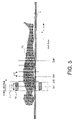
- FIG. 5 shows a movement of a data detecting unit along a body axis in the embodiment shown in FIG. 1 .
- FIG. 6 is a flowchart for showing an image data generation process in an embodiment consistent with the present invention.
- FIG. 7 shows the first to the Nth monitoring periods in the embodiment shown in FIG. 6 and a plurality of simultaneous detection times being set in each of these monitoring periods.
- FIG. 8 illustrates a modification of body moving ratio calculation method in the embodiment shown in FIG. 6 .
- FIGS. 1-8 embodiments consistent with the present invention will be explained.
- the nuclear medicine imaging apparatus consistent with the present invention, it will be explained as to a PET apparatus.
- the present invention is applicable to nuclear medicine imaging apparatus for other image diagnosis apparatus, such as a SPECT apparatus or a composite type PET apparatus with an X-ray CT apparatus.
- An object (patient) has previously been administered (injected) a radioactive isotope before being positioned into a nuclear medicine imaging apparatus consistent with the present invention.
- a pair of gamma-rays emitted from a diagnostic portion in the patient with the radioactive isotope is successively detected by a detector of a ring-like configuration that is comprised of a plurality of detector modules.
- projection data (hereinafter simply referred to as monitoring data) are generated for use in a monitoring operation in conformity with a detected position of a gamma-ray in the detector module and an incident direction of the gamma-ray to the detector.
- a body movement index an index that indicates an amount of body movement of a patient (hereinafter simply referred to as “a body movement index”).
- the body movement index is calculated by comparing between count values of monitoring data that are obtained in two adjoining monitoring periods. If the body movement index indicates a bigger value than a predetermined threshold value, an alarm signal is displayed on a display unit of the apparatus. Based on the alarm signal, an operator restarts the detection of gamma-rays and generation of monitoring data in accordance with an inputted command signal.
- each count value of the monitoring data obtained in each of the plural monitoring periods is integrated with each of a gamma-ray detected position and a gamma-ray incident direction in order to generate projection data.
- Image data is generated by performing a reconstruction process using the generated projection data.
- FIG. 1 is a block diagram illustrating a whole construction of a nuclear medicine imaging apparatus of an embodiment according to this invention.
- FIG. 2 illustrates a construction of a detector module provided in the nuclear medicine imaging apparatus.
- nuclear medicine imaging apparatus 100 includes a data detection unit 1 that is comprised of a plurality of detector modules 1 to Nm provided in a ring-like configuration, a data processing unit 2 configured to process detection data from each detector module in data detecting unit 1 , an incident direction calculating unit 3 configured to calculate incident directions of gamma-rays using detection signals from data processing unit 2 , a projection data generating unit 4 and a projection data monitoring unit 5 .
- Data detecting unit 1 is provided in a ring-like configuration around a patient 150 who has been administered with a radioactive isotope (RI) in order to detect a pair of gamma-rays emitted from the patient 150 .
- RI radioactive isotope
- Data processing unit 2 includes a plurality of data processing units 21 - 1 to 21 -Nm corresponding to each of the plurality of detector modules 1 to Nm. Data processing unit 2 discriminates gamma-rays detected in the data detecting unit 1 from noise. Further it sets the respective detection position and detection time for the pair of gamma-rays. Incident direction calculating unit 3 extracts a pair of gamma-rays which are simultaneously detected and calculates gamma-ray incident directions based on the pair of gamma-ray detecting positions.
- Projection data generating unit 4 successively stores each count value of gamma-rays in a predetermined period as to each of the pair of gamma-ray detecting positions and each of the gamma-ray incident directions in order to generate monitoring data and projection data.
- Projection data monitoring unit 5 calculates a body movement index by comparing among count values of monitoring data which are generated in each of adjoining monitoring periods.
- Nuclear medicine imaging apparatus 100 is further comprised of an image data generating unit 6 , a display unit 7 , a top plate 8 , a top plate/gantry driving mechanism unit 9 , an input unit 10 and a system control unit 11 .
- Image data generating unit 6 generates image data by performing a reconstruction process of projection data generated in the projection data generating unit 4 .
- Display unit 7 displays the generated image data.
- Object (patient) 150 is placed on top plate 8 .
- Top plate/gantry driving mechanism unit 9 moves a gantry (not shown) provided on the data detecting unit 1 or the top plate 8 along a body axis direction of the patient 150 .
- Input unit 10 (described in more detail below) allows projection data generating conditions and input operations of various command signals to be set.
- System controlling unit 11 controls each of the above-mentioned units.
- Data detecting unit 1 includes a plurality of detector modules 12 - 1 to 12 -Nm which are provided as a ring-like configuration.
- a patient (object) 150 lying on the top plate 8 is inserted at a center portion of the detector ring.
- Gamma-rays emitted from the patient 150 are once converted to visible radiations through each of the detector modules 12 - 1 to 12 -Nm and then converted to detection signals.
- the gamma-rays emitted from a diagnostic portion are detected.
- FIG. 2 shows a practical construction of each of the plurality of detector modules 12 - 1 to 12 -Nm provided in a ring-like arrangement.
- Each detector module 12 includes strip frames of Na 1 pieces arranged in a ring-like direction and Na 2 pieces arranged in a body axis direction.
- Each detector module 12 further includes a plurality of scintillators 121 for detecting each gamma-ray and converting it to visible radiation.
- the plurality of scintillators 121 is comprised of Nb 1 pieces arranged in a ring-like direction and Nb 2 pieces arranged in a body axis direction.
- Visible radiations converted in the scintillators 121 are converted to electric signals and also amplified in a plurality of multiplier photoelectron tubes 122 .
- Each detector module 12 further includes a light guide 123 for transmitting visible radiation emitted from each scintillator 121 to each multiplier photoelectron tube 122 .
- the number of scintillators 121 is shown as eight (8) pieces of Na 1 frames arranged in a ring-like direction and 6 pieces of Na 2 frames arranged in body axis direction.
- the number Nb 1 of multiplier photoelectron tube is shown as four (4) and the number of Nb 2 of multiplier photoelectron tube is shown as three (3).
- the invention is not limited to these numbers.
- the scintillator 121 for example, bismuth germanide (BGO: Bi 4 Ge 3 O 12 ), thallium activated sodium iodide (NaI(Tl)), barium fluoride (BaF 2 ) are usually used.
- BGO bismuth germanide
- NaI(Tl) thallium activated sodium iodide
- BaF 2 barium fluoride
- a scintillator material that has a high photoelectric absorption rate such as Bi 4 Ge 3 O 12 or a scintillator material that has a quick response speed such as BaF 2 .
- Each multiplier photoelectron tube 122 includes a photocathode and an electron multiplier.
- the tube amplifies several hundreds of photons into 10 7 to 10 10 of electrons.
- the multiplier photoelectron tube collects these electrons at an anode at an output stage and converts it to an electrical signal.
- a multi-alkali substance having a wavelength characteristic that is substantially the same as a luminescence wavelength of the scintillator 121 or a bi-alkali potassium substance being activated by oxygen or cesium is used as the photocathode. Generally, 20 to 30 percent of photoelectrons are generated from the total number of incidence photons.
- the electron multiplier tube is comprised of multi-staged electrodes which are arranged along transmitting paths of electrons based on secondary electron discharge phenomenon and anodes for collecting amplified electrons.
- a tube voltage is set at 200V (volts) to 300V
- an amplifying ratio of one stage becomes about five times. Consequently, about ten (10) stages of electrodes are usually provided in order to acquire the above-mentioned amplifying ratio of 10 7 .
- Light guide 123 optically couples scintillator 121 and multiplier photoelectron tube 122 .
- a plastic material having an effective light transmittance is usually used as a light guide 123 .
- data processing unit 2 includes a plurality of data processing units 21 - 1 to 21 -Nm, each of which is respectively coupled to one of the plurality of detector modules 12 - 1 to 12 -Nm.
- data processing unit 2 includes a plurality of data processing units 21 - 1 to 21 -Nm, each of which is respectively coupled to one of the plurality of detector modules 12 - 1 to 12 -Nm.
- data processing unit 2 includes a plurality of data processing units 21 - 1 to 21 -Nm, each of which is respectively coupled to one of the plurality of detector modules 12 - 1 to 12 -Nm.
- Each of data processing units 21 - 1 a and 21 - b includes a detection position calculating unit 26 configured to calculate gamma-ray detection positions at the detector module 12 based on detection signals of three Nb 3 channels supplied from the multiplier photoelectron tubes 122 and a detection position setting unit 27 configured to add the gamma-ray detection position to detection signals being set a gamma-ray detection time in the detection time setting unit 25 .
- signal composition unit 22 and detection position calculating unit 26 in each of data processing units 21 - a and 21 - b will be explained in more detail.
- it is the function of the data processing unit for processing detection signals supplied from multiplier photoelectron tubes 122 that are disposed in a ring-like arrangement direction are explained.
- a gamma-ray radiated from an object 150 is detected at a center position of the scintillator 121 shown in FIG. 3A .
- sensitivity i.e., amplitude
- sensitivity i.e., amplitude
- a detection signal outputted from a multiplier photoelectron tube 122 depends on a propagation length of visible radiation that is propagated in a light guide 123 .
- the propagation length becomes longer, the sensitivity becomes smaller.
- these relations become a 0 >a 1 >a 2 .
- the amplitude Sg of a detection signal outputted from signal composition unit 22 is obtained by the following equation (1).
- Sg a 0+2 a 1+2 a 2 (1)
- the amplitude Sg of the compounded detection signal supplied from the signal composition unit 22 is acquired by the above-mentioned equation (1).
- each gamma-ray detection position is calculated in a ring-like arrangement direction by using scintillator 121 and multiplier photoelectron tube 122 in the detector modules 12 provided in a ring-like arrangement direction 12 .
- detection positions in a body axis direction based on the detection signals obtained from scintillator 121 and multiplier photoelectron tube 122 provided in the body axis direction.
- each wave height discriminator 23 in the data processing units 21 - a and 21 - b includes a memory circuit (not shown) and a comparison circuit (not shown).
- the memory circuit wave in the height discriminator 23 preliminarily stores a threshold value ⁇ .
- the threshold value ⁇ is used for discriminating detection signals from noises.
- the comparison circuit in the wave height discriminator 23 compares between the threshold value ⁇ and peak values of the detection signals supplied from signal composition unit 22 . By the comparison, the detection signals having a larger peak value than the threshold value ⁇ are judged as the detection signals that are detected due to the original gamma-ray radiation.
- Waveform shaping unit 24 in each of data processing unit generates a rectangular wave by amplifying each compounded detection signal outputted from signal composition unit 22 . Then, detection time setting unit 25 measures a gamma-ray detection time based on a generation timing of, for example, at a front edge of the rectangular wave. Further, detection time setting unit 25 sets the gamma-ray detection time for discriminated detection signal at speak value discrimination unit 23 .
- Detection position setting unit 27 in each data processing unit sets up each gamma-ray detection position being calculated in detection position calculating unit 26 to each detection signal to which each gamma-ray detection time is added in detection time setting unit 25 .
- each detection signal outputted from detection position setting unit 27 has added thereto the gamma-ray detection time and the gamma-ray detection position as affixed data.
- data of gamma-ray detection position is added to each detection signal to which each gamma-ray detection time is added in the data processing unit.
- each data processing unit that is respectively connected to each detector module also includes a signal composition unit 22 , a wave height discriminator 23 , a waveform shaping unit 24 , a detection time setting unit 25 , a detection position calculating unit 26 and a detection position setting unit 27 in order to work as similarly as explained the above.
- An incident direction calculating unit 3 in the nuclear medicine imaging apparatus 100 extracts each detection signal that is simultaneously measured at a predetermined detection time ⁇ 0 based on each gamma-ray detection time supplied from each of processing units 21 - 1 to 21 Nm. For instance, each detection signal based on a radioactive isotope S supplied from a pair of a first detector module 12 - a and a second detector module 12 - b is extracted. Each gamma-ray incident direction is calculated based on the gamma-ray detection position data affixed to these detection signals.
- a projection data generating unit 4 in the nuclear medicine imaging apparatus 100 includes a memory circuit (not shown) in order to store a count value of each detection signal supplied from the incident direction calculating unit 3 so as to correspond to each of a gamma-ray detection position and a gamma-ray incident direction. Whenever detection of a gamma-ray is performed through the pair of the respective detector modules 12 - a and 12 - b , each count value of the detection signal is integrated in the memory circuit.
- each gamma-ray detection position and each gamma-ray incident direction are designated by a similar method as explained above.
- each count value of the detection signals is successively stored in the memory circuit with correspondence to the respective gamma-ray detection position and the gamma-ray incident direction.
- the memory circuit in the projection data generating unit 4 integrates each count value of the detection signals corresponding to the plurality of gamma-ray detection positions and the plurality of gamma-ray incident directions during a monitoring time period ⁇ f in order to generate monitoring data.
- the projection data generating unit 4 further generates projection data by compounding a plurality of monitoring data that is acquired during a predetermined data collecting time period ⁇ x ( ⁇ x> ⁇ f).
- a projection data monitoring unit 5 in the nuclear medicine imaging apparatus 100 includes a memory circuit (not shown) and an operation circuit (not shown).
- the memory circuit stores a threshold value 8 in advance.
- the operation circuit calculates a body movement index ⁇ Cx indicating influences due to body movements of an object by comparing each of two count values C of the monitoring data that have been acquired in two monitoring periods designated in adjoining times. When the body movement index ⁇ Cx exceeds a threshold value ⁇ , an instruction signal is supplied to the system controlling unit 11 in order to generate an alarm signal.
- ⁇ ⁇ ⁇ Cx ⁇ ( Tm , Tm - 1 ) ⁇ i ⁇ ⁇ j ⁇ ⁇ n ⁇ ( C ⁇ ( Pi , ⁇ ⁇ ⁇ j , Zn , Tm ) - C ⁇ ( Pi , ⁇ ⁇ ⁇ j , Zn , Tm - 1 ) ) 2 ⁇ i ⁇ ⁇ j ⁇ ⁇ n ⁇ C ⁇ ( Pi , ⁇ ⁇ ⁇ j , Zn , Tm ) ( 4 )
- count values of gamma rays are stored in correspondence with gamma ray detection positions and gamma ray incident directions to a data detecting unit in order to calculate a difference between the count values of the gamma ray data collected in a first time period and a second time period against each of the detected position data. Based on the difference, the controller in the apparatus judges whether recollection of gamma ray detection data should be performed. According to the judgment, scanning control of repetition of data collection is executed.
- Image data generating unit 6 in the nuclear medicine imaging apparatus 100 includes a operation circuit (not shown) and a memory circuit (not shown).
- Image data generating unit 6 generates image data by using projection data generated in projection data generating unit 4 at a data collecting time ⁇ x.
- the operation circuit performs, for example, a reverse projection process that is usually performed in an X-ray CT apparatus. Further, depending upon necessity, it generates image data by performing signal processes such as a smoothing process and an interpolating process.
- the obtained image data are stored in the memory circuit.
- a display unit 7 in the nuclear medicine imaging apparatus 100 includes a display data generation circuit (not shown), a conversion circuit (not shown) and a monitor (not shown).
- the displayed data generation circuit reads out image data generated by the image data generating unit 6 and generates displayed data by converting the read image data into a predetermined display format.
- the conversion circuit performs digital/analog (D/A) conversion and television (TV) format conversion of the displayed data.
- the acquired image signals are displayed on the monitor.
- the system control unit 11 supplies an alarm signal so as to be displayed on the monitor based on a result of the comparison between the body movement index ⁇ Cx in the projection data monitoring unit 5 and a threshold value ⁇ .
- a top plate 8 in the nuclear medicine imaging apparatus 100 is provided on an upper surface of a bed (not shown) so as to slide an object 150 lying on the plate in a predetermined distance along a body axis direction in order to set up a data detecting unit 1 on a particular diagnostic portion of the object. Further, a top plate/gantry driving mechanism unit 9 moves a top plate 8 or a gantry provided in the data detecting unit 1 in a desired direction or to a desired position in accordance with control signals supplied from the system control unit 11 so as to set up the data detecting unit 1 at the diagnostic portion.
- the top plate 8 or the data detecting unit 1 By moving the top plate 8 or the data detecting unit 1 at predetermined distances so as to generate image data, it becomes possible to perform an inspection for a wide range of diagnostic areas of the object 150 in a short time. In this embodiment, it supposed that the image data of such a wide range are collected by moving the data detecting unit 1 . Of course it is also possible to move the top plate 8 in order to collect wide range image data.
- FIG. 5 illustrates how to move the data detecting unit 1 in a direction along a body axis Z of an object 150 .
- a ring-like detector module 12 that is arrayed in one plane being perpendicular to a body axis direction is used to generate monitoring data and projection data so as to generate projection data for one cross-sectional image.
- the plurality of detector modules 12 - 1 to 12 -Nm provided in the data detecting unit 1 includes Na 2 scintillators 121 and Nb 2 multiplier photoelectron tubes 122 in the body axis direction, too. Consequently, it becomes possible to generate monitoring data and projection data that can generate a plurality of two dimensional image data or three dimensional image data (volume data ) being perpendicular to the body axis direction in a short time.
- a pair of gamma-rays detected by the detector module 12 is not limited to a plane being perpendicular to the body axis direction but also a slant plane, it becomes possible to generate three dimensional projection data.
- the moving scope ⁇ Z is usually set up so as to be ⁇ Z ⁇ Zx.
- input devices such as a keyboard, a track ball, a joy stick and a mouse
- various setting up operations are performed. Thus, setting up operations of projection data generating conditions, such as input of an object data, a data collecting time ⁇ x, monitoring a data collecting time ⁇ f, and a moving scope of
- a system control unit 11 in nuclear medicine imaging apparatus 100 includes a central processing unit (CPU) and a memory circuit (not shown).
- the system control unit 11 stores input data or setting data supplied from the input unit 10 to the memory circuit, and generates and displays image data based on the input data by controlling each unit in the apparatus. Further if the body movement index ⁇ Cx calculated by the projection data monitoring unit 5 exceeds a threshold value 6 , an alarm signal is supplied to the display unit 7 .
- an operator injects a radioactive isotope (RI) to an object 150 .
- RI radioactive isotope
- a compound being marked with positron emission nuclides such as 11 C, 13 N, 15 O and 18 F, is used (step S 1 ).
- the object 150 with an RI is placed on top plate 8 (step S 2 ).
- the inputted data or set up data through the input unit 10 are stored in a memory circuit in the system control unit 11 .
- step S 4 the operator inputs a command for starting generation of projection data through the input unit 10 (step S 4 ).
- the plurality of detector modules 12 - 1 to 12 -Nm of the data detecting unit 1 provided surrounding the object 150 detects a pair of gamma-ray of the radioactive isotope successively emitted from a body of the object with RI.
- the detected gamma-rays are converted into detection signals of Nb 3 channels and supplied to a signal composition unit 22 and a detection position calculating unit 26 in data processing units 21 - 1 to 21 -Nm of the data processing unit 2 .
- the signal composition unit 22 composes signals by adding detection signals of Nb 3 channel supplied from each of the detector modules 12 - 1 to 12 -Nm.
- the composed detection signals are supplied to a wave height discriminator 23 and a waveform shaping unit 24 , respectively.
- the wave height discriminator 23 discriminates noise by comparing the supplied detection signals and a predetermined threshold value ⁇ .
- the waveform shaping unit 24 shapes the detection signals into rectangular waves.
- the detection time setting unit 25 measures a gamma-ray detection time in the data detecting unit 1 based on a timing of a front edge of a rectangular wave supplied from the waveform shaping unit 24 . Further, the detection time setting unit 25 adds the gamma-ray detection time to the detection signals that are discriminated in the wave height discriminator 23 .
- the detection position calculating unit 26 that received detection signals of Nb 3 channels from the detector modules 12 - 1 to 12 -Nm calculates gamma-ray detection positions in the data detecting unit 1 by the method as explained in FIG. 3 .
- the detection position setting unit 27 adds gamma-ray detection position data supplied from the detection position calculating unit 26 to detection signals provided from the detection time setting unit 25 and supplies detection signals having data of a gamma-ray detection time and a gamma-ray detection position to the incident direction calculating unit 3 .
- the incident direction calculating unit 3 that is supplied the detection signals from each of data processing units 21 - 1 to 21 -Nm corresponding to each of detector modules 12 - 1 to 12 -Nm extracts detection signals during the same detection time ⁇ 0 based on gamma-ray detection time data affixed to the detection signals. Further, a gamma-ray incident direction is calculated based on gamma-ray detection position data affixed to these detection signals.
- the projection data monitoring unit 5 calculates a body movement index ⁇ Cx that indicates body movement of the object using the count values in the first monitoring data and the second monitoring data to, for example, the formula (4) ( FIG. 6 , step S 6 ).
- System control unit 11 When the acquired body movement index ⁇ Cx exceeds a preliminary determined threshold value ⁇ , a result of the comparison is supplied to the system control unit 11 .
- System control unit 11 generates an alarm signal based on the comparison result and displays the alarm on a display unit 7 ( FIG. 6 , step S 7 ).
- An operator who observes the alarm signal judges whether or not generation of projection data should be restarted.
- a command for restarting generation of projection data is input through the input unit 10 (step S 8 ).
- the system control unit 11 receives this command signal controls each units in the nuclear medicine imaging apparatus 100 so as to restart generation of monitoring data from the first monitoring period [T 1 ⁇ T 2 ].
- a third generation of monitoring data at a third monitoring period [T 3 ⁇ T 4 ] is executed.
- a body movement index ⁇ Cx calculated based on a count value of the third monitoring data and a count value of the second monitoring data is compared with the threshold value ⁇ . Based on a result of the comparison, an alarm signal may be displayed ( FIG. 6 , steps S 5 to S 7 )
- Such a procedure is restarted up to a generation of monitoring data at a predetermined Nth monitoring period [TN ⁇ T(N+1)].
- N a predetermined Nth monitoring period
- generation of monitoring data is restarted by returning to the first monitoring period [T 1 ⁇ T 2 ] ( FIG. 6 , steps S 5 to S 8 ).
- the projection data generating unit 4 when the generation of projection data for the first monitoring data up to for the Nth monitoring data is completed without inputting a command for repetition, the projection data generating unit 4 generates projection data by compounding these monitoring data.
- the projection data is supplied to the image data generating unit 6 .
- the image data generating unit 6 performs a reconstruction process of the projection data so as to generate image data for display on the display unit 7 ( FIG. 6 , step S 9 ).
- FIG. 7 shows the first monitoring period [T 1 ⁇ T 2 ], the second monitoring period [T 2 ⁇ T 3 ], - - - , and the Nth monitoring period [TN ⁇ T(N+1)] for generating the first to the Nth monitoring data.
- the respective size of each monitoring period is determined by an initially set up monitoring time ⁇ f.
- a plurality of measuring periods having a simultaneous detection time ⁇ 0 is substantially continuously set up.
- a detection signal due to a pair of gamma-rays emitted from the same positron nuclide is extracted.
- Typical values of the above-explained same detection time ⁇ 0 , monitoring time ⁇ f and data collecting time ⁇ x are 5n to 10n seconds, two seconds and two minutes, respectively. Thus, during generation of one projection data, it can generate about sixty monitoring data.
- a plurality of successive monitoring periods during the generation period of projection data is set up and a count value of monitoring data generated in an adjoining monitoring period is successively compared so as to detect body movement of an object.
- the projection data used in a reconstruction process for aiming generation of image data can be generated by compounding monitoring data that are generated in a plurality of monitoring periods, the projection data can be efficiently generated.
- Zn 1 and Zn 2 indicate z coordinates of detector modules 12 - 1 and 12 - b by which a pair of gamma-rays is detected, and Zn 1 ⁇ Zn 2 indicates that these detector modules 12 - a and 12 - b do not exist on the same plane being perpendicular to the body axis.
- ⁇ ⁇ ⁇ Cx ⁇ ( Tm , Tm - 1 ) ⁇ i ⁇ ⁇ j ⁇ ⁇ n ⁇ ⁇ 1 ⁇ ⁇ n ⁇ ⁇ 2 ⁇ ( C ⁇ ( Pi , ⁇ ⁇ ⁇ j , Zn ⁇ ⁇ 1 , Zn ⁇ ⁇ 2 , Tm ) - C ⁇ ( Pi , ⁇ ⁇ ⁇ j , Zn ⁇ ⁇ 1 , Zn ⁇ ⁇ 2 , Tm + 1 ) ) 2 ⁇ i ⁇ ⁇ j ⁇ ⁇ n ⁇ 1 ⁇ ⁇ n ⁇ ⁇ 2 ⁇ C ⁇ ( Pi , ⁇ ⁇ ⁇ j , Zn ⁇ ⁇ 1 , Zn ⁇ ⁇ 2 , Tm ) ( 5 )
- the data detecting unit 1 is moved together with a gantry along a body axis direction.
- the top plate 8 it is possible to move the top plate 8 in an opposite direction instead of moving the data detecting unit 1 .
- repetition of projection data is performed based on a command signal that is inputted by an operator after observing an alarm signal displayed on a display unit when a body movement index ⁇ Cx exceeds a threshold value ⁇ .
- the system according to the invention can also automatically perform repetition of projection data generation based on a result of comparison between a body movement index ⁇ Cx and a threshold value ⁇ .
- the starting point is not limited to such a position but can be performed at any position when a non-permissible body movement has occurred.
- the present invention is also not limited to displaying an alarm signal on a monitor in a display unit 7 but it is also possible to display the alarm signal on a display of an input unit 10 . Further it is possible to inform an operator of an alarm condition by a voice supplied from an audio output unit that is separately provided.
- the data detecting unit 1 has previously stored a threshold value ⁇ , a threshold value ⁇ , the same detection time ⁇ 0 and a body axis direction moving scope ⁇ Z. These values, of course, may also be initially be set by an input unit 10 similar to the data collecting time ⁇ x and monitoring time ⁇ f.
- a body movement index ⁇ Cx is calculated by using all projection data obtained in an area ⁇ Zx. It is also possible to calculate the body movement index by using arbitrary projection data at one or plural cross-sections being perpendicular to a body axis direction.
- two monitoring periods need not be strictly adjoining. It is also permissible to compare projection data that are acquired, for example at two nonadjoining periods, such as monitoring period [T 1 ⁇ T 2 ] and monitoring period [T 3 ⁇ T 4 ] (T 2 ⁇ T 3 ).
Abstract
Description
-
- a direction calculating unit configured to acquire emitting directions of the gamma rays based on the detected gamma-rays data;
- a first time counting unit configured to acquire each count value of the gamma rays for each emission in a first time period;
- a second time counting unit configured to acquire each count value of the gamma rays for each emission in a second time period; and
- an operation unit configured to acquire the sum of; and a judging unit configured to judge whether a body movement has occurred based on a difference between the count value in the first time period and the count value in the second time period for the respective output from the first time counting unit and the second time counting unit.
-
- a data detection unit configured to detect gamma-rays emitted from a predetermined portion in the object;
- a detection position calculation unit configured to calculate each position of the detected gamma-ray in the data detection unit;
- an incident direction calculation unit configured to calculate each incident direction of the incident direction in the data detection unit;
- a projection data generating unit configured to generate a plurality of monitoring projection data in a time series by storing each count value of each detection signal being successively obtained through the data detection unit in corresponded to each detection position of the gamma-ray and each incident direction of the gamma-ray;
- a projection data monitoring unit configured to monitor time changes of the count values of the projection data being monitored;
- a projection data generation control unit configured to control regenerate monitoring projection data to the predetermined portion of the object based on a monitoring result of the projection data monitoring unit; and
- an image data generation unit configured to generate image data by performing a reconstruction process of projection data based on the plurality of monitoring projection data acquired by regenerating data.
-
- detecting gamma rays emitted from a predetermined diagnosis portion of an object with a radioisotope;
- calculating an incident direction of the gamma ray to the detector based on the detected gamma rays data;
- acquiring a first count value of gamma rays for the respective incident directions to the detector during a first time period;
- acquiring a second count value of gamma rays for the respective incident directions to the detector during a second time period;
- judging whether a body movement of the object has occurred based on a difference between the first count value in the first time period and the second count value in the second time period; and generating a distribution image of the radioisotope in the object based on the judging.
Sg=a0+2a1+2a2 (1)
Claims (21)
Applications Claiming Priority (2)
| Application Number | Priority Date | Filing Date | Title |
|---|---|---|---|
| JP2005298717A JP2007107995A (en) | 2005-10-13 | 2005-10-13 | Nuclear medicine imaging device and image data generation method |
| JP2005-298717 | 2005-10-13 |
Publications (2)
| Publication Number | Publication Date |
|---|---|
| US20070096028A1 US20070096028A1 (en) | 2007-05-03 |
| US7718971B2 true US7718971B2 (en) | 2010-05-18 |
Family
ID=37995032
Family Applications (1)
| Application Number | Title | Priority Date | Filing Date |
|---|---|---|---|
| US11/549,509 Active 2027-06-20 US7718971B2 (en) | 2005-10-13 | 2006-10-13 | Nuclear medicine imaging apparatus and a method for generating image data |
Country Status (2)
| Country | Link |
|---|---|
| US (1) | US7718971B2 (en) |
| JP (1) | JP2007107995A (en) |
Cited By (5)
| Publication number | Priority date | Publication date | Assignee | Title |
|---|---|---|---|---|
| US20100289813A1 (en) * | 2009-05-13 | 2010-11-18 | Kabushiki Kaisha Toshiba | Nuclear medical imaging apparatus, image processing apparatus, and image processing method |
| US20100294944A1 (en) * | 2007-10-26 | 2010-11-25 | Tetsuo Furumiya | Radiation detector |
| CN102727237A (en) * | 2011-04-06 | 2012-10-17 | 株式会社东芝 | Medical image diagnostic apparatus and control method |
| US10126438B2 (en) | 2014-09-19 | 2018-11-13 | University Of Virginia Patent Foundation | Systems and methods for polarized nuclear imaging and spectroscopy |
| US11754652B2 (en) | 2016-09-15 | 2023-09-12 | University Of Virginia Patent Foundation | Systems and methods for polarized nuclear imaging and spectroscopy |
Families Citing this family (23)
| Publication number | Priority date | Publication date | Assignee | Title |
|---|---|---|---|---|
| US20060079753A1 (en) * | 2004-09-27 | 2006-04-13 | Michael Gurley | Pre-acquisition identification of region for image acquisition time optimization for radiation imaging systems |
| GB0606026D0 (en) * | 2006-03-25 | 2006-05-03 | Lab Impex Systems Ltd | Radioactivity monitoring apparatus |
| CN107102348B (en) * | 2008-12-10 | 2020-12-22 | 皇家飞利浦电子股份有限公司 | Autonomous detector module for use as a building block for scalable PET and SPECT systems |
| CN102781331B (en) * | 2009-12-10 | 2015-08-05 | 皇家飞利浦电子股份有限公司 | Flight-time information is used to detect the method and apparatus with the motion in correcting imaging scanning |
| JP5598905B2 (en) * | 2010-02-26 | 2014-10-01 | 独立行政法人日本原子力研究開発機構 | Neutron image detection method and neutron image detector using the method |
| JP2011252860A (en) | 2010-06-03 | 2011-12-15 | Toshiba Corp | Radiation imaging apparatus, method and program |
| JP5813994B2 (en) | 2010-06-03 | 2015-11-17 | 株式会社東芝 | Medical image diagnostic apparatus and image reconstruction method |
| JP2012013681A (en) * | 2010-06-04 | 2012-01-19 | Toshiba Corp | Nuclear medicine imaging device, method, and program |
| JP2012013680A (en) | 2010-06-04 | 2012-01-19 | Toshiba Corp | Radiation imaging apparatus, method and program |
| US9029786B2 (en) | 2010-06-17 | 2015-05-12 | Kabushiki Kaisha Toshiba | Nuclear medicine imaging apparatus, and nuclear medicine imaging method |
| JP5925444B2 (en) | 2010-08-04 | 2016-05-25 | 株式会社東芝 | Radiation diagnostic apparatus and control method |
| CN102439483B (en) | 2010-08-09 | 2014-05-28 | 株式会社东芝 | Nuclear medicine imaging device, and nuclear medicine imaging method |
| JP5815218B2 (en) | 2010-08-30 | 2015-11-17 | 株式会社東芝 | Radiotherapy apparatus, control method, and control program |
| EP2565679B1 (en) | 2010-08-31 | 2019-09-25 | Toshiba Medical Systems Corporation | Nuclear medicine imaging device and control method |
| JP5872241B2 (en) * | 2010-10-29 | 2016-03-01 | 株式会社東芝 | Positron emission tomography system |
| JP2016128840A (en) * | 2011-04-06 | 2016-07-14 | 東芝メディカルシステムズ株式会社 | Nuclear medicine diagnosis system |
| EP2535866A1 (en) * | 2011-06-16 | 2012-12-19 | Agfa HealthCare | Method to detect and indicate inaccuracies in long length imaging |
| US8937285B2 (en) * | 2012-06-18 | 2015-01-20 | General Electric Company | Methods and systems for signal communication in gamma ray detectors |
| DE102012216292B4 (en) * | 2012-09-13 | 2021-02-18 | Siemens Healthcare Gmbh | Magnetic resonance assembly, a magnetic resonance device with the magnetic resonance assembly and a method for determining a movement of a patient during a magnetic resonance examination |
| US9146323B1 (en) * | 2014-08-13 | 2015-09-29 | Kabushiki Kaisha Toshiba | Position dependent electronic power sequencing |
| CN110244660B (en) * | 2019-05-07 | 2020-01-31 | 广东明峰医疗科技有限公司 | peripheral configurable CT/PET-CT motion control system |
| CN111419256A (en) * | 2020-03-26 | 2020-07-17 | 青岛大学附属医院 | Nuclear medicine imaging system, device and imaging method |
| CN115031808B (en) * | 2022-05-26 | 2023-07-21 | 西安航空学院 | Material level meter and detection method thereof |
Citations (5)
| Publication number | Priority date | Publication date | Assignee | Title |
|---|---|---|---|---|
| US5703369A (en) * | 1995-10-20 | 1997-12-30 | Hamamatsu Photonics K.K. | Positron emission computed tomography apparatus and image reconstruction method |
| US6239438B1 (en) * | 1998-11-19 | 2001-05-29 | General Electric Company | Dual acquisition imaging method and apparatus |
| JP2002090458A (en) | 2000-09-14 | 2002-03-27 | Shimadzu Corp | Ect apparatus |
| US7154096B2 (en) * | 2003-10-17 | 2006-12-26 | Shimadzu Corporation | Diagnostic imaging device for medical use |
| US7282723B2 (en) * | 2002-07-09 | 2007-10-16 | Medispectra, Inc. | Methods and apparatus for processing spectral data for use in tissue characterization |
-
2005
- 2005-10-13 JP JP2005298717A patent/JP2007107995A/en not_active Withdrawn
-
2006
- 2006-10-13 US US11/549,509 patent/US7718971B2/en active Active
Patent Citations (5)
| Publication number | Priority date | Publication date | Assignee | Title |
|---|---|---|---|---|
| US5703369A (en) * | 1995-10-20 | 1997-12-30 | Hamamatsu Photonics K.K. | Positron emission computed tomography apparatus and image reconstruction method |
| US6239438B1 (en) * | 1998-11-19 | 2001-05-29 | General Electric Company | Dual acquisition imaging method and apparatus |
| JP2002090458A (en) | 2000-09-14 | 2002-03-27 | Shimadzu Corp | Ect apparatus |
| US7282723B2 (en) * | 2002-07-09 | 2007-10-16 | Medispectra, Inc. | Methods and apparatus for processing spectral data for use in tissue characterization |
| US7154096B2 (en) * | 2003-10-17 | 2006-12-26 | Shimadzu Corporation | Diagnostic imaging device for medical use |
Cited By (7)
| Publication number | Priority date | Publication date | Assignee | Title |
|---|---|---|---|---|
| US20100294944A1 (en) * | 2007-10-26 | 2010-11-25 | Tetsuo Furumiya | Radiation detector |
| US8269183B2 (en) * | 2007-10-26 | 2012-09-18 | Shimadzu Corporation | Radiation detector |
| US20100289813A1 (en) * | 2009-05-13 | 2010-11-18 | Kabushiki Kaisha Toshiba | Nuclear medical imaging apparatus, image processing apparatus, and image processing method |
| US9392980B2 (en) * | 2009-05-13 | 2016-07-19 | Kabushiki Kaisha Toshiba | Nuclear medical imaging apparatus, image processing apparatus, and image processing method |
| CN102727237A (en) * | 2011-04-06 | 2012-10-17 | 株式会社东芝 | Medical image diagnostic apparatus and control method |
| US10126438B2 (en) | 2014-09-19 | 2018-11-13 | University Of Virginia Patent Foundation | Systems and methods for polarized nuclear imaging and spectroscopy |
| US11754652B2 (en) | 2016-09-15 | 2023-09-12 | University Of Virginia Patent Foundation | Systems and methods for polarized nuclear imaging and spectroscopy |
Also Published As
| Publication number | Publication date |
|---|---|
| JP2007107995A (en) | 2007-04-26 |
| US20070096028A1 (en) | 2007-05-03 |
Similar Documents
| Publication | Publication Date | Title |
|---|---|---|
| US7718971B2 (en) | Nuclear medicine imaging apparatus and a method for generating image data | |
| US6965661B2 (en) | Radiological imaging apparatus and radiological imaging method | |
| KR100991640B1 (en) | Nuclear medical diagnostic device, form tomography diagnostic device, data arithmetic processing method for nuclear medicine, and form tomogram image processing method | |
| US7053376B2 (en) | Radiological imaging apparatus and radiological imaging method and radiological imaging support method | |
| US9029786B2 (en) | Nuclear medicine imaging apparatus, and nuclear medicine imaging method | |
| EP2638858B1 (en) | Diagnostic imaging device and method | |
| WO2002049499A2 (en) | Systems and methods for cardiovascular imaging, cardiovascular functional analysis, and detecting coronary artery disease | |
| US8625868B2 (en) | Radiation diagnostic apparatus and image reconstructing method | |
| JP2006078486A (en) | Detecting apparatus for medical diagnostic equipment and medical imaging diagnostic method | |
| JP6058272B2 (en) | Nuclear medicine diagnostic apparatus and control method | |
| JP6502105B2 (en) | Nuclear medicine imaging apparatus and control method | |
| US9134441B2 (en) | Tomographic equipment, imaging system provided therewith, and imaging data acquisition method | |
| JP5376623B2 (en) | Radiation detector | |
| JP6026089B2 (en) | Medical image diagnostic apparatus, image information display apparatus, and control program | |
| JP3851575B2 (en) | PET inspection equipment | |
| ITRM950353A1 (en) | EQUIPMENT FOR SCINTIGRAPHIC ANALYSIS, IN PARTICULAR MAMMOGRAPH WITH SUB-MILLIMETER SPACE RESOLUTION. | |
| JP6878131B2 (en) | Medical diagnostic imaging equipment | |
| JP2010256176A (en) | Nuclear medicine diagnosis system, and administration dose calculation method of the same | |
| JP2003090882A (en) | Radiographic examination system | |
| JP2011163966A (en) | Medical imagery diagnostic apparatus and control program for radiation dose calculation | |
| JPH0933659A (en) | Positron ct equipment | |
| JP4737104B2 (en) | Method for calculating position information of photon detector and positron CT apparatus using the same | |
| JP2000249766A (en) | Nuclear medical diagnostic device | |
| JP2013085622A (en) | Medical image diagnostic apparatus, medical image display device, and control program | |
| JP5454859B2 (en) | Nuclear medicine diagnostic apparatus and image processing apparatus |
Legal Events
| Date | Code | Title | Description |
|---|---|---|---|
| AS | Assignment |
Owner name: KABUSHIKI KAISHA TOSHIBA,JAPAN Free format text: ASSIGNMENT OF ASSIGNORS INTEREST;ASSIGNOR:TANAKA, TAKASHI;REEL/FRAME:018778/0829 Effective date: 20061114 Owner name: TOSHIBA MEDICAL SYSTEMS CORPORATION,JAPAN Free format text: ASSIGNMENT OF ASSIGNORS INTEREST;ASSIGNOR:TANAKA, TAKASHI;REEL/FRAME:018778/0829 Effective date: 20061114 Owner name: TOSHIBA MEDICAL SYSTEMS CORPORATION, JAPAN Free format text: ASSIGNMENT OF ASSIGNORS INTEREST;ASSIGNOR:TANAKA, TAKASHI;REEL/FRAME:018778/0829 Effective date: 20061114 Owner name: KABUSHIKI KAISHA TOSHIBA, JAPAN Free format text: ASSIGNMENT OF ASSIGNORS INTEREST;ASSIGNOR:TANAKA, TAKASHI;REEL/FRAME:018778/0829 Effective date: 20061114 |
|
| STCF | Information on status: patent grant |
Free format text: PATENTED CASE |
|
| FEPP | Fee payment procedure |
Free format text: PAYOR NUMBER ASSIGNED (ORIGINAL EVENT CODE: ASPN); ENTITY STATUS OF PATENT OWNER: LARGE ENTITY |
|
| FPAY | Fee payment |
Year of fee payment: 4 |
|
| AS | Assignment |
Owner name: TOSHIBA MEDICAL SYSTEMS CORPORATION, JAPAN Free format text: ASSIGNMENT OF ASSIGNORS INTEREST;ASSIGNOR:KABUSHIKI KAISHA TOSHIBA;REEL/FRAME:038891/0693 Effective date: 20160316 |
|
| MAFP | Maintenance fee payment |
Free format text: PAYMENT OF MAINTENANCE FEE, 8TH YEAR, LARGE ENTITY (ORIGINAL EVENT CODE: M1552) Year of fee payment: 8 |
|
| MAFP | Maintenance fee payment |
Free format text: PAYMENT OF MAINTENANCE FEE, 12TH YEAR, LARGE ENTITY (ORIGINAL EVENT CODE: M1553); ENTITY STATUS OF PATENT OWNER: LARGE ENTITY Year of fee payment: 12 |