US7719252B2 - Power supply - Google Patents
Power supply Download PDFInfo
- Publication number
- US7719252B2 US7719252B2 US11/628,778 US62877805A US7719252B2 US 7719252 B2 US7719252 B2 US 7719252B2 US 62877805 A US62877805 A US 62877805A US 7719252 B2 US7719252 B2 US 7719252B2
- Authority
- US
- United States
- Prior art keywords
- fuel cell
- converter
- voltage
- pwm signal
- current
- Prior art date
- Legal status (The legal status is an assumption and is not a legal conclusion. Google has not performed a legal analysis and makes no representation as to the accuracy of the status listed.)
- Expired - Fee Related, expires
Links
Images


Classifications
-
- H—ELECTRICITY
- H02—GENERATION; CONVERSION OR DISTRIBUTION OF ELECTRIC POWER
- H02J—CIRCUIT ARRANGEMENTS OR SYSTEMS FOR SUPPLYING OR DISTRIBUTING ELECTRIC POWER; SYSTEMS FOR STORING ELECTRIC ENERGY
- H02J7/00—Circuit arrangements for charging or depolarising batteries or for supplying loads from batteries
- H02J7/34—Parallel operation in networks using both storage and other dc sources, e.g. providing buffering
-
- G—PHYSICS
- G05—CONTROLLING; REGULATING
- G05F—SYSTEMS FOR REGULATING ELECTRIC OR MAGNETIC VARIABLES
- G05F1/00—Automatic systems in which deviations of an electric quantity from one or more predetermined values are detected at the output of the system and fed back to a device within the system to restore the detected quantity to its predetermined value or values, i.e. retroactive systems
- G05F1/66—Regulating electric power
- G05F1/67—Regulating electric power to the maximum power available from a generator, e.g. from solar cell
-
- H—ELECTRICITY
- H01—ELECTRIC ELEMENTS
- H01M—PROCESSES OR MEANS, e.g. BATTERIES, FOR THE DIRECT CONVERSION OF CHEMICAL ENERGY INTO ELECTRICAL ENERGY
- H01M8/00—Fuel cells; Manufacture thereof
-
- H—ELECTRICITY
- H01—ELECTRIC ELEMENTS
- H01M—PROCESSES OR MEANS, e.g. BATTERIES, FOR THE DIRECT CONVERSION OF CHEMICAL ENERGY INTO ELECTRICAL ENERGY
- H01M8/00—Fuel cells; Manufacture thereof
- H01M8/04—Auxiliary arrangements, e.g. for control of pressure or for circulation of fluids
- H01M8/04082—Arrangements for control of reactant parameters, e.g. pressure or concentration
- H01M8/04186—Arrangements for control of reactant parameters, e.g. pressure or concentration of liquid-charged or electrolyte-charged reactants
-
- H—ELECTRICITY
- H01—ELECTRIC ELEMENTS
- H01M—PROCESSES OR MEANS, e.g. BATTERIES, FOR THE DIRECT CONVERSION OF CHEMICAL ENERGY INTO ELECTRICAL ENERGY
- H01M8/00—Fuel cells; Manufacture thereof
- H01M8/04—Auxiliary arrangements, e.g. for control of pressure or for circulation of fluids
- H01M8/04298—Processes for controlling fuel cells or fuel cell systems
- H01M8/04313—Processes for controlling fuel cells or fuel cell systems characterised by the detection or assessment of variables; characterised by the detection or assessment of failure or abnormal function
- H01M8/04537—Electric variables
- H01M8/04544—Voltage
- H01M8/04559—Voltage of fuel cell stacks
-
- H—ELECTRICITY
- H01—ELECTRIC ELEMENTS
- H01M—PROCESSES OR MEANS, e.g. BATTERIES, FOR THE DIRECT CONVERSION OF CHEMICAL ENERGY INTO ELECTRICAL ENERGY
- H01M8/00—Fuel cells; Manufacture thereof
- H01M8/04—Auxiliary arrangements, e.g. for control of pressure or for circulation of fluids
- H01M8/04298—Processes for controlling fuel cells or fuel cell systems
- H01M8/04694—Processes for controlling fuel cells or fuel cell systems characterised by variables to be controlled
- H01M8/04858—Electric variables
- H01M8/04925—Power, energy, capacity or load
- H01M8/0494—Power, energy, capacity or load of fuel cell stacks
-
- H—ELECTRICITY
- H01—ELECTRIC ELEMENTS
- H01M—PROCESSES OR MEANS, e.g. BATTERIES, FOR THE DIRECT CONVERSION OF CHEMICAL ENERGY INTO ELECTRICAL ENERGY
- H01M8/00—Fuel cells; Manufacture thereof
- H01M8/04—Auxiliary arrangements, e.g. for control of pressure or for circulation of fluids
- H01M8/04298—Processes for controlling fuel cells or fuel cell systems
- H01M8/04992—Processes for controlling fuel cells or fuel cell systems characterised by the implementation of mathematical or computational algorithms, e.g. feedback control loops, fuzzy logic, neural networks or artificial intelligence
-
- H—ELECTRICITY
- H01—ELECTRIC ELEMENTS
- H01M—PROCESSES OR MEANS, e.g. BATTERIES, FOR THE DIRECT CONVERSION OF CHEMICAL ENERGY INTO ELECTRICAL ENERGY
- H01M8/00—Fuel cells; Manufacture thereof
- H01M8/10—Fuel cells with solid electrolytes
-
- H—ELECTRICITY
- H01—ELECTRIC ELEMENTS
- H01M—PROCESSES OR MEANS, e.g. BATTERIES, FOR THE DIRECT CONVERSION OF CHEMICAL ENERGY INTO ELECTRICAL ENERGY
- H01M8/00—Fuel cells; Manufacture thereof
- H01M8/06—Combination of fuel cells with means for production of reactants or for treatment of residues
- H01M8/0662—Treatment of gaseous reactants or gaseous residues, e.g. cleaning
-
- H—ELECTRICITY
- H01—ELECTRIC ELEMENTS
- H01M—PROCESSES OR MEANS, e.g. BATTERIES, FOR THE DIRECT CONVERSION OF CHEMICAL ENERGY INTO ELECTRICAL ENERGY
- H01M8/00—Fuel cells; Manufacture thereof
- H01M8/10—Fuel cells with solid electrolytes
- H01M8/1009—Fuel cells with solid electrolytes with one of the reactants being liquid, solid or liquid-charged
- H01M8/1011—Direct alcohol fuel cells [DAFC], e.g. direct methanol fuel cells [DMFC]
-
- Y—GENERAL TAGGING OF NEW TECHNOLOGICAL DEVELOPMENTS; GENERAL TAGGING OF CROSS-SECTIONAL TECHNOLOGIES SPANNING OVER SEVERAL SECTIONS OF THE IPC; TECHNICAL SUBJECTS COVERED BY FORMER USPC CROSS-REFERENCE ART COLLECTIONS [XRACs] AND DIGESTS
- Y02—TECHNOLOGIES OR APPLICATIONS FOR MITIGATION OR ADAPTATION AGAINST CLIMATE CHANGE
- Y02E—REDUCTION OF GREENHOUSE GAS [GHG] EMISSIONS, RELATED TO ENERGY GENERATION, TRANSMISSION OR DISTRIBUTION
- Y02E60/00—Enabling technologies; Technologies with a potential or indirect contribution to GHG emissions mitigation
- Y02E60/30—Hydrogen technology
- Y02E60/50—Fuel cells
Definitions
- the present invention relates to a power supply equipped with a fuel cell.
- DMFC direct methanol fuel cell
- the DMFC includes a fuel circulation type that collects an unused fuel cell from supplied methanol for reuse, and a fuel non-circulation type that does not reuse unused methanol.
- the fuel circulation type can readily obtain a stable generated output by stabilizing the operating point. It has, however, a drawback that the need for a collecting mechanism (circulation pump or the like) to collect unused methanol complicates the configuration and the device is increased in size. Meanwhile, the fuel non-circulation type can achieve a size reduction of the device because it does not need the collecting mechanism. However, it is not preferable to release a large volume of methanol, which is poisonous. In addition, in terms of enhancing generation efficiency, it is crucial to use up supplied methanol almost completely, that is, to allow supplied methanol to burn completely.
- FIG. 11 is a graph showing the current-to-voltage characteristic, the current-to-power characteristic, and the release ratio characteristic for a quantity of supplied methanol (fuel) in the DMFC.
- the ordinate is used for an output voltage (V), output power (W), and a release ratio (%) of the DMFC, and the abscissa is used for an output current (A) of the DMFC.
- C 11 through C 13 are the current-to-voltage characteristic curves when quantities of supplied fuel are 0.1 cc/min, 0.2 cc/min, and 0.3 cc/min, respectively.
- C 21 through C 23 are the current-to-power characteristic curves when quantities of supplied fuel are 0.1 cc/min, 0.2 cc/min, and 0.3 cc/min, respectively.
- C 31 shows a relation of an output current and a release ratio when a quantity of supplied fuel is 0.3 cc/min.
- the release ratio is defined as a ratio of released fuel with respect to supplied fuel expressed in percentage.
- Patent Document 1 discloses a fuel cell voltage generator comprising a DC-DC converter connected to the output side of the fuel cell, a rechargeable battery connected to the output side of the DC-DC converter, and a switch controller that supplies a PWM signal to the DC-DC converter, in which the switch controller calculates a duty ratio of the PWM signal on the basis of a difference between an output voltage of the fuel cell and the reference value.
- Patent Document 2 discloses a power supply comprising a fuel cell, a DC converter, a rechargeable battery, and a micro processor that controls the DC converter, in which the maximum value of a current flowing into the DC converter is varied for the voltage of the fuel cell to fall within a specific range including the maximum power.
- Both the fuel cell voltage generator shown in Patent Document 1 and the power supply shown in Patent Document 2 use a voltage or a current outputted from the fuel cell, that is, a voltage or a current inputted into the DC-DC converter, as a negative feedback signal.
- This configuration poses a problem that when a voltage needed for the load device increases abruptly and the gain of the DC-DC converter increases abruptly, a voltage outputted from the fuel cell starts to oscillate and the like, which makes a generated output unstable.
- circuits such as a circuit that compares the voltage of the fuel cell with the reference value and a circuit that varies the duty ratio in response to a difference between these two values, another problem arises that the size of the circuitry becomes relatively large.
- the invention therefore has an object to provide a power supply capable of stabilizing a generated output of the fuel cell using neither a voltage nor a current outputted from the fuel cell.
- a power supply of the invention is characterized by including: a fuel cell; a DC-DC converter that adjusts a voltage outputted from the fuel cell, and then outputs the voltage to a load device connected thereto in parallel; signal generating means for generating a PWM signal that controls the DC-DC converter and outputting the PWM signal to the DC-DC converter; a rechargeable battery connected to the load device in parallel; and voltmeter means for measuring a voltage outputted from the DC-DC converter, wherein the signal generating means calculates a duty ratio of the PWM signal on the basis of a target fuel cell voltage indicating a target value of the voltage outputted from the fuel cell and a measured value of the voltage measured by the voltmeter means.
- a voltage outputted from the fuel cell is adjusted by the DC-DC converter, and then outputted to the load device connected thereto in parallel.
- the rechargeable battery charged with power outputted from the DC-DC converter is connected to the load device in parallel, and when power for the load device is insufficient, the rechargeable battery covers a shortfall of the power by discharging.
- a voltage outputted from the DC-DC converter is measured by the voltmeter means.
- the duty ratio of the PWM signal outputted to the DC-DC converter is calculated on the basis of the measured voltage and the target fuel cell voltage indicating the target value of the voltage outputted from the fuel cell.
- the DC-DC converter is controlled with the PWM signal having the duty ratio thus calculated.
- the DC-DC converter is controlled using a voltage outputted from the DC-DC converter without using a voltage outputted from the fuel cell as a negative feedback signal, it is possible to prevent the voltage outputted from the fuel cell from oscillating, which can in turn stabilize a generated output of the fuel cell while supplying the load device with necessary power.
- circuits such as a circuit that compares the voltage of the fuel cell with the reference value and a circuit that varies the duty ratio in response to a difference between these values, the size of the circuitry can be reduced.
- a power supply of the invention is characterized by including: a fuel cell; a DC-DC converter that adjusts a voltage outputted from the fuel cell, and then outputs the voltage to a load device connected thereto in parallel; signal generating means for generating a PWM signal that controls the DC-DC converter and outputting the PWM signal to the DC-DC converter; a rechargeable battery connected to the load device in parallel; and ammeter means for measuring a current outputted from the DC-DC converter, wherein the signal generating means calculates a duty ratio of the PWM signal on the basis of a target fuel cell current indicating a target value of the current outputted from the fuel cell and a measured value of the current measured by the ammeter means.
- a voltage outputted from the fuel cell is adjusted by the DC-DC converter, and then outputted to the load device connected thereto in parallel.
- the rechargeable battery charged with power outputted from the DC-DC converter is connected to the load device in parallel, and when power for the load device is insufficient, the rechargeable battery covers a shortfall of the power by discharging.
- a current outputted from the DC-DC converter is measured by the ammeter means.
- the duty ratio of the PWM signal outputted to the DC-DC converter is calculated on the basis of the measured current and the target fuel cell current indicating the target value of the current outputted from the fuel cell.
- the DC-DC converter is controlled with the PWM signal having the duty ratio thus calculated.
- the DC-DC converter is controlled using a current outputted from the DC-DC converter without using a voltage outputted from the fuel cell as a negative feedback signal, it is possible to prevent the voltage outputted from the fuel cell from oscillating, which can in turn stabilize a generated output of the fuel cell while supplying the load device with necessary power.
- circuits such as a circuit that compares the voltage of the fuel cell with the reference value and a circuit that varies the duty ratio in response to a difference between these values, the size of the circuitry can be reduced.
- a power supply of the invention is characterized by including: a fuel cell; a DC-DC converter that adjusts a voltage outputted from the fuel cell, and then outputs the voltage to a load device connected thereto in parallel; signal generating means for generating a PWM signal that controls the DC-DC converter and outputting the PWM signal to the DC-DC converter; a rechargeable battery connected to the load device in parallel; voltmeter means for measuring a voltage outputted from the DC-DC converter; and ammeter means for measuring a current outputted from the DC-DC converter, wherein the signal generating means calculates a duty ratio of the PWM signal on the basis of a target fuel cell voltage indicating a target value of the voltage outputted from the fuel cell or a target fuel cell current indicating a target value of the current outputted from the fuel cell, a measured value of the voltage measured by the voltmeter means, and a measured value of the current measured by the ammeter means.
- a voltage outputted from the fuel cell is adjusted by the DC-DC converter, and then outputted to the load device connected thereto in parallel.
- the rechargeable battery charged with power outputted from the DC-DC converter is connected to the load device in parallel, and when power for the load device is insufficient, the rechargeable battery covers a shortfall of the power by discharging.
- a voltage and a current outputted from the DC-DC converter are measured by the voltmeter means and the ammeter means, respectively.
- the duty ratio of the PWM signal outputted to the DC-DC converter is calculated on the basis of the measured voltage and current, and the target fuel cell voltage indicating the target value of the voltage outputted from the fuel cell or the target fuel cell current indicating the target value of the current outputted from the fuel cell.
- the DC-DC converter is controlled with the PWM signal having the duty ratio thus calculated.
- the DC-DC converter is controlled using the voltage and the current outputted from the DC-DC converter without using a voltage outputted from the fuel cell as a negative feedback signal, it is possible to prevent the voltage outputted from the fuel cell from oscillating. Then, DC-DC converter can in turn stabilize a generated output of the fuel cell while supplying the load device with necessary power.
- circuits such as a circuit that compares the voltage of the fuel cell with the reference value and a circuit that varies the duty ratio in response to a difference between these values, size of the circuitry can be reduced.
- FIG. 1 is block diagram of a power supply according to a first embodiment of the invention.
- FIG. 2 is a view used to describe a duty ratio.
- FIG. 3 is a circuit diagram showing the configuration of a boost type DC-DC converter.
- FIG. 4 is a circuit diagram showing the configuration of a buck type DC-DC converter.
- FIG. 5 is a circuit diagram showing the configuration of an inverter type DC-DC converter.
- FIG. 6 is a circuit diagram showing the configuration of a SEPIC type DC-DC converter.
- FIG. 7 is a block diagram showing the configuration of the power supply according to a fifth embodiment.
- FIG. 8 is a block diagram showing the configuration of the power supply according to a ninth embodiment.
- FIG. 9 is a block diagram showing the configuration of the power supply according to a thirteenth embodiment.
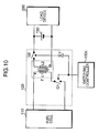
- FIG. 10 is a circuit diagram showing the configuration of a flyback type DC-DC converter.
- FIG. 11 is a graph showing the current-to-voltage characteristic, the current-to-power characteristic, and the release ratio characteristic for a quantity of supplied methanol (fuel) in a DMFC.
- FIG. 1 is a block diagram of a power supply according to a first embodiment of the invention.
- the power supply includes a fuel cell 110 , a DC-DC converter 120 , a switching controller 130 , a voltmeter 140 , a rechargeable battery 150 , and a control portion 160 .
- the fuel cell 110 has an output terminal connected to an input terminal of the DC-DC converter 120 .
- the DC-DC converter 120 has an output terminal connected to the rechargeable battery 150 and a load device 200 in parallel.
- the voltmeter 140 is connected between the cathode-side output terminal of the DC-DC converter 120 and the switching controller 130 .
- the fuel cell 110 is a DMFC of the fuel non-circulation type, and includes a cell stack 111 , a fuel supply device 112 , a purifying portion 113 , a dilution tank 114 , a methanol tank 115 , and pumps 116 through 119 .
- the fuel supply device 112 adjusts quantities of fuel and air supplied to the fuel cell 110 by controlling the pumps 116 through 119 according to instructions from the control portion 160 .
- the cell stack 111 comprises one or plural fuel cell-cells 111 a connected in series.
- the fuel cell-cell 111 a includes a fuel electrode (anode) to which fuel is supplied and an air electrode (cathode) to which air is supplied.
- methanol and water are reacted to generate carbon dioxide, hydrogen ions, and electrons (CH 3 OH+H 2 O ⁇ CO 2 +6H + +6e ⁇ ).
- hydrogen ions generated at the fuel electrode and air are reacted to generate water (3/2O 2 +6H + +6e ⁇ ⁇ 3H 2 O).
- the Gibbs energy generated from this reaction is converted to electric energy for a direct current to be outputted from the fuel cell 110 .
- the purifying portion 113 changes unconsumed methanol released from the cell stack 111 to carbon dioxide and water to purify unconsumed methanol (CH 3 OH).
- the methanol tank 115 stores methanol at specific concentration.
- the pump 117 supplies methanol to the dilution tank 114 under the control of the fuel supply device 112 .
- the pump 116 supplies water released from the cell stack 111 to the dilution tank 114 under the control of the fuel supply device 112 .
- the dilution tank 114 stores methanol diluted to specific concentration.
- the pump 119 supplies air to the cell stack 111 under the control of the fuel supply device 112 .
- the pump 118 supplies methanol stored in the dilution tank 114 to the cell stack 111 under the control of the fuel supply device 112 .
- the DC-DC converter 120 is a boost type DC-DC converter, which receives a PWM signal outputted from the switching controller 130 and outputs a voltage outputted from the fuel cell 110 to the load device 200 by boosting the voltage outputted from the fuel cell 110 to stay at a pre-set target fuel cell voltage.
- the voltmeter 140 comprises an A/D converter, and measures a voltage Vout outputted from the DC-DC converter 120 and outputs this voltage to the switching controller 130 .
- the rechargeable battery 150 is charged by excessive power when power outputted from the DC-DC converter 120 is excessive, and supplies the load device 200 with power to cover a shortfall when power outputted from the DC-DC converter 120 is insufficient. This enables the rechargeable battery 150 to absorb an abrupt variance of power in the load device 200 .
- the switching controller 130 comprises a CPU, a PWM signal generator, and the like.
- the controller 130 calculates a duty ratio D of a PWM signal outputted to the DC-DC converter 120 by performing a computation expressed by Equation (1) using a target fuel cell voltage Vt set by the control portion 160 and the voltage Vout, which is measured by the voltmeter 140 , outputted from the DC-DC converter 120 , thereby generating a PWM signal having the duty ratio D thus calculated.
- D [%] (1 ⁇ Vt/V out) ⁇ 100[%] (1)
- FIG. 2 is a view used to describe the duty ratio.
- the duty ratio indicates a ratio of a high level period Ton of a pulse signal with respect to a cycle T of the pulse signal.
- the cycle T of the PWM signal is kept constant.
- the cycle T of the PWM signal is kept constant. It should be noted that a most adequate value has been previously set to the cycle T by taking into account the magnitude of a ripple current, the size of the coil, and so forth.
- the load device 200 comprises a mobile electronic device, such as a notebook personal computer and a mobile phone.
- the control portion 160 controls the fuel supply device 112 in such a manner that a constant quantity of methanol is supplied from the dilution tank 114 to the cell stack 111 , and the portion 160 also outputs the target fuel cell voltage Vt, which has been set previously in response to a quantity of methanol to be supplied, to the switching controller 130 .
- control portion 160 is provided with a memory device (not shown) having stored a target value determination table in which a quantity of supplied methanol is correlated with a target fuel cell voltage pre-set for a supplied quantity, and the portion 160 determines the target fuel cell voltage Vt with reference to this target value determination table.
- the target value determination table has stored, as the target fuel cell voltage, a voltage having the operating point at the power maximum point P in the current-voltage characteristic curve shown in FIG. 11 specified for each quantity of supplied methanol.
- the target fuel cell voltage is a value obtained from experiments or the like.
- FIG. 3 is a circuit diagram showing the configuration of the boost type DC-DC converter.
- the boost type DC-DC converter includes a coil L 1 , two switches Q 1 and Q 2 , and an inverting circuit I 1 .
- the coil L 1 is connected to the cathode of the input terminal of the fuel cell 110 at one end and to the switch Q 1 at the other end.
- the switch Q 2 is connected to the coil L 1 and the switch Q 1 at one end and to the negative electrode of the rechargeable battery 150 at the other end.
- the switches Q 1 and Q 2 include a control terminal to which the PWM signal is inputted.
- the switches Q 1 and Q 2 comprise transistors, such as a bipolar transistor and a field-effect transistor, and the switches Q 1 and Q 2 come ON upon input of a high-level signal at the control terminal and go OFF upon input of a low-level signal.
- bipolar transistors are adopted as the switches Q 1 and Q 2
- the base terminal is the control terminal
- the field-effect transistors are adopted, the gate is the control terminal.
- the inverting circuit I 1 inverts the logic of the PWM signal by inverting a high-level period of the PWM signal to a low level and a low-level period to a high level, and outputs the resulting signal to the switch Q 2 .
- the switches Q 1 and Q 2 come ON and go OFF in a complimentary manner so that when one of the transistors comes ON, the other transistor goes OFF.
- the boost type DC-DC converter configured as has been described stores energy in the coil L 1 when the switch Q 1 stays ON, and outputs stored energy by superimposing this energy on the energy of the fuel cell 110 when the switch Q 1 stays OFF. The voltage outputted from the fuel cell 110 is thus boosted.
- the boost type DC-DC converter 120 shown in FIG. 3 boosts a voltage Vin inputted from the fuel cell 110 to a voltage Vout, and outputs the boosted voltage to the load device 200 .
- the boosting ratio is determined in accordance with Equation (1-1).
- V out/ V in 1/(1 ⁇ D ) (1-1)
- the voltage Vout is determined by an electromotive force and charging and discharging currents of the rechargeable battery 150 .
- Equation (1) By replacing Vin in Equation (1-2) with the target fuel cell voltage Vt of the fuel cell, we get Equation (1).
- the PWM signal whose duty ratio D is calculated in accordance with Equation (1) using the voltage Vout and the target fuel cell voltage Vt of the fuel cell, to the DC-DC converter 120 , it is possible to control the voltage Vin from the fuel cell 110 to stay at the target fuel cell voltage Vt, which can in turn stabilize the operating point of the fuel cell 110 .
- the duty ratio D is calculated by measuring the voltage Vout outputted from the DC-DC converter 120 without using a voltage outputted from the fuel cell 110 as a negative feedback signal, it is possible to prevent the voltage outputted from the fuel cell from oscillating and thereby becoming unstable. This makes it possible to stabilize a generated output of the fuel cell while supplying necessary power to the load device 200 .
- the number of components can be reduced because the A/D converter is used as the voltmeter 140 and the CPU as the switching controller 130 .
- a rectifying device such as a diode
- the switch Q 2 a rectifying device, such as a diode
- a current flowing through the coil L 1 does not change continuously when the current flowing through the coil L 1 becomes small.
- Equation (1-1) is not established. It is therefore impossible to control the voltage outputted from the fuel cell 110 to stay at a constant level even when the duty ratio D is determined in accordance with Equation (1).
- FIG. 4 is a circuit diagram showing the configuration of the buck type DC-DC converter.
- the buck type DC-DC converter includes a coil L 1 , two switches Q 1 and Q 2 , and an inverting circuit I 1 .
- the same elements are labeled with the same reference numerals with respect to FIG. 3 , and descriptions of these elements are omitted.
- the switch Q 1 is connected to the cathode-side output terminal of the fuel cell 110 at one end and to the switch Q 2 and the coil L 1 at the other end.
- the coil L 1 is connected to the negative electrode of the rechargeable battery 150 at one end.
- the switch Q 2 is connected to the anode-side output terminal of the fuel cell 110 and the positive electrode of the rechargeable battery 150 at one end.
- the inverting circuit I 1 circuit I 1 is connected between the switching controller 130 and the control terminal of the switch Q 2 .
- the switches Q 1 and Q 2 come ON and go OFF in a complementary manner with the PWM signal in the same manner as the switches Q 1 and Q 2 shown in FIG. 3 .
- the buck type DC-DC converter configured in this manner steps down the voltage inputted from the fuel cell 110 , and outputs this voltage toward the load device 200 .
- the switching controller 130 performs a computation in accordance with Equation (2) to calculate the duty ratio D of the PWM signal.
- D [%] ( Vt/V out) ⁇ 100 (2) where D is the duty ratio, Vout is the voltage Vout measured by the voltmeter 140 , and Vt is the target fuel cell voltage Vt set by the control portion 160 .
- FIG. 5 is a circuit diagram showing the configuration of the inverter type DC-DC converter.
- the same elements are labeled with the same reference numerals with respect to FIG. 3 , and descriptions of these elements are omitted.
- the inverter type DC-DC converter includes two switches Q 1 and Q 2 , a coil L 1 , and an inverting circuit I 1 .
- the switch Q 1 is connected to the cathode of the fuel cell 110 at one end and to the coil L 1 and the switch Q 2 at the other end.
- the switch Q 2 is connected to the negative electrode of the rechargeable battery 150 at one end.
- the coil L 1 is connected to the anode-side output terminal of the fuel cell 110 and the positive electrode of the rechargeable battery 150 at one end.
- the inverting circuit I 1 is connected between the control terminal of the switch Q 2 and the switching controller 130 .
- the switching controller 130 performs a computation expressed by Equation (3) to calculate the duty ratio D of the PWM signal.
- D [%] (1/(1 ⁇ Vt/V out)) ⁇ 100 (3) where Vout is the voltage measured by the voltmeter 140 , and Vt is the target fuel cell voltage Vt set by the control portion 160 .
- the power supply according to a fourth embodiment will now be described. Because the overall configuration of the power supply of the fourth embodiment is the same as the overall configuration of the power supply of the first embodiment, descriptions will be given using FIG. 1 .
- the power supply of the fourth embodiment is characterized by using a SEPIC type DC-DC converter as the DC-DC converter 120 in the power supply of the first embodiment.
- FIG. 6 is a circuit diagram showing the configuration of the SEPIC type DC-DC converter.
- the SEPIC type DC-DC converter includes two switches Q 1 and Q 2 , coils L 1 and L 2 , a capacitor C 1 , and an inverting circuit I 1 .
- the coil L 1 is connected to the cathode of the fuel cell 110 at one end and to the switch Q 1 and the capacitor C 1 at the other end.
- the capacitor C 1 is connected to the coil L 2 and the switch Q 2 at one end.
- Both the switch Q 1 and the coil L 2 are connected to the anode-side output terminal of the fuel cell 110 and the positive electrode of the rechargeable battery 150 at one end.
- the inverting circuit I 1 is connected between the control terminal of the switch Q 2 and the switching controller 130 .
- the switches Q 1 and Q 2 come ON and go OFF in a complementary manner with the PWM signal.
- the switching controller 130 performs a computation expressed by Equation (4) to calculate the duty ratio D of the PWM signal.
- D [%] (1/(1 +Vt/V out)) ⁇ 100[%] (4)
- Vout is the voltage Vout measured by the voltmeter 140
- Vt is the target fuel cell voltage Vt set by the control portion 160 .
- the duty ratio D of the PWM signal is calculated in accordance with Equation (4) and the switch Q 2 is connected, it is possible to achieve the same advantages achieved by the power supply of the first embodiment when the SEPIC type DC-DC converter is used.
- FIG. 7 is a block diagram showing the configuration of the power supply of the fifth embodiment.
- the power supply of the fifth embodiment is characterized by including an ammeter 170 instead of the voltmeter 140 in the power supply of the first embodiment, and by calculating the duty ratio D of the PWM signal using a current Iout outputted from the DC-DC converter 120 and a pre-set target fuel cell current It of the fuel cell 110 .
- the same components are labeled with the same reference numerals with respect to the power supply of the first embodiment, and descriptions of these components are omitted.
- the cell stack 111 alone is shown for the fuel cell 110 and the other members are not shown in the drawing.
- the ammeter 170 is connected between the cathode-side output terminal of the DC-DC converter 120 and the switching controller 130 a , so that the ammeter 170 measures a current outputted from the DC-DC converter 120 and outputs this current to the switching controller 130 a .
- the ammeter 170 comprises an A/D converter or the like.
- the DC-DC converter 120 comprises the boost type DC-DC converter shown in FIG. 3 .
- the control portion 160 a sets the target fuel cell current It that has been set previously in response to a quantity of methanol to be supplied to the cell stack 111 , and outputs this value to the switching controller 130 a .
- the portion 160 a includes a memory device (not shown) having stored a target value determination table in which a quantity of supplied methanol is correlated with the target fuel cell current It pre-set for a supplied quantity, and determines the target fuel cell current It with reference to this target value determination table.
- the target value determination table has stored a current such that sets the operating point of the fuel cell 110 to the power maximum point as the target fuel cell current It.
- the switching controller 130 a calculates the duty ratio D of the PWM signal to be outputted to the DC-DC converter 120 by performing a computation expressed by Equation (5) using the current Iout measured by the ammeter 170 and the target fuel cell current It set by the control portion 160 a , thereby generating the PWM signal having the calculated duty ratio D thus generated.
- D [%] (1 ⁇ I out/ It ) ⁇ 100[%] (5)
- Equation (5) The power conversion efficiency ⁇ of the DC-DC converter 120 is defined by Equation (5-1).
- the power conversion efficiency ⁇ is normally equal to or smaller than 1, and indicates a power loss of the DC-DC converter 120 .
- the power loss is attributed to a power loss or the like caused by resistance of the switches and the coil.
- the power conversion efficiency ⁇ can be specified by a function using the current Iin outputted from the fuel cell 110 as an argument.
- Equation (5-1) is modified to Equation (5-2).
- I out/ I in ⁇ ( V in/ V out) (5-2)
- Equation (5-3) ( ⁇ I out/( ⁇ I in)) ⁇ 100
- the duty ratio D is calculated in accordance with Equation (5) and the switch Q 2 is connected, it is possible to achieve the same advantages achieved in the first embodiment even when the boost type DC-DC converter is adopted and the duty ratio is calculated using the current Iout outputted from the DC-DC converter 120 .
- the power supply according to a sixth embodiment will now be described. Because the overall configuration of the power supply of the sixth embodiment is the same as the overall configuration of the power supply of the sixth embodiment, descriptions will be given using FIG. 7 .
- the power supply of the sixth embodiment is characterized by using a buck type DC-DC converter shown in FIG. 4 as the DC-DC converter 120 in the power supply of the fifth embodiment.
- the switching controller 130 a performs a computation in accordance with Equation (6) to calculate the duty ratio D of the PWM signal.
- D [%] ( I out/ It ) ⁇ 100 (6)
- the duty ratio D of the PWM signal is calculated in accordance with Equation (6) and the switch Q 2 is connected, it is possible to achieve the same advantages achieved by the power supply of the first embodiment even when the buck type DC-DC converter is used and the duty ratio D is calculated using the current Iout outputted from the DC-DC converter 120 .
- the power supply according to a seventh embodiment will now be described. Because the overall configuration of the power supply of the seventh embodiment is the same as the overall configuration of the power supply of the fifth embodiment, descriptions will be given using FIG. 7 .
- the power supply of the seventh embodiment is characterized by using an inverter type DC-DC converter shown in FIG. 5 as the DC-DC converter 120 in the power supply of the fifth embodiment.
- the switching controller 130 a performs a computation in accordance with Equation (7) to calculate the duty ratio D of the PWM signal.
- D [%] (1/(1 ⁇ I out/ It )) ⁇ 100[%] (7)
- the duty ratio D of the PWM signal is calculated in accordance with Equation (7) and the switch Q 2 is connected, it is possible to achieve the same advantages achieved by the power supply of the first embodiment even when the inverter type DC-DC converter is used and the duty ratio D is calculated using the current Iout outputted from the DC-DC converter 120 .
- the power supply according to an eighth embodiment will now be described. Because the overall configuration of the power supply of the eighth embodiment is the same as the overall configuration of the power supply of the fifth embodiment, descriptions will be given using FIG. 7 .
- the power supply of the eighth embodiment is characterized by using a SEPIC type DC-DC converter shown in FIG. 6 as the DC-DC converter 120 in the power supply of the fifth embodiment.
- the switching controller 130 a performs a computation in accordance with Equation (8) to calculate the duty ratio D of the PWM signal.
- D [%] (1/(1 +I out/ It )) ⁇ 100 (8)
- Equation (8) is derived from Equation (5-1) and Equation (4) as with Equation (5).
- the duty ratio D of the PWM signal is calculated in accordance with Equation (8) and the switch Q 2 is connected, it is possible to achieve the same advantages achieved by the power supply of the first embodiment even when the SEPIC type DC-DC converter is used and the duty ratio D is calculated using the current Iout outputted from the DC-DC converter 120 .
- the power supply according to a ninth embodiment will now be described.
- the power supply of the ninth embodiment is characterized by calculating the duty ratio D by further taking the power conversion efficiency ⁇ into account in the power supply of the fifth embodiment.
- FIG. 8 is a block diagram showing the overall configuration of the power supply of the ninth embodiment.
- the same components are labeled with the same reference numerals with respect to FIG. 7 , and descriptions of these components are omitted.
- the switching controller 130 b includes an ⁇ calculation portion 131 b .
- the ⁇ calculation portion 131 b calculates the power conversion efficiency ⁇ of the DC-DC converter 120 .
- the power conversion efficiency ⁇ is expressed by a specific function using the target fuel cell current It as an argument.
- the ⁇ calculation portion 131 b therefore calculates the power conversion efficiency ⁇ by substituting the target fuel cell current It set by the control portion 160 b into the specific function.
- a conversion table indicating the relation of the target fuel cell current It and the power conversion efficiency ⁇ with respect to the target fuel cell current It may be stored in a memory device (not shown), so that the ⁇ calculation portion 131 b specifies the power conversion efficiency ⁇ using this conversion table.
- the DC-DC converter 120 comprises a boost type DC-DC converter shown in FIG. 3 .
- the switching controller 130 b calculates the duty ratio D of the PWM signal by performing a computation in accordance with Equation (9) using the target fuel cell current It set by the control portion 160 b and the current Iout measured by the ammeter 170 .
- D (%) (1 ⁇ I out/( ⁇ It )) ⁇ 100 (9)
- the duty ratio D of the PWM signal is calculated by taking the power conversion efficiency ⁇ into account, in addition to the advantages achieved in the first embodiment, it is possible to generate the PWM signal, for which a power loss caused by resistance of the transistor and the coil has been corrected. This configuration can in turn make a generated output of the fuel cell more stable.
- the power supply according to a tenth embodiment will now be described. Because the overall configuration of the power supply of the tenth embodiment is the same as the overall configuration of the power supply of the ninth embodiment, descriptions will be given using FIG. 8 .
- the power supply of the tenth embodiment is characterized by using a buck type DC-DC converter shown in FIG. 4 as the DC-DC converter 120 in the power supply of the ninth embodiment.
- the switching controller 130 b performs a computation in accordance with Equation (10) to calculate the duty ratio D of the PWM signal.
- D [%] ( I out/ ⁇ It ) ⁇ 100 (10)
- the power supply according to an eleventh embodiment will now be described. Because the overall configuration of the power supply of the eleventh embodiment is the same as the overall configuration of the power supply of the ninth embodiment, descriptions will be given using FIG. 8 .
- the power supply of the eleventh embodiment is characterized by using an inverter type DC-DC converter shown in FIG. 5 as the DC-DC converter 120 in the power supply of the ninth embodiment.
- the switching controller 130 b performs a computation in accordance with Equation (11) to calculate the duty ratio D of the PWM signal.
- D [%] (1/(1 ⁇ I out/ ⁇ It )) ⁇ 100 (11)
- the power supply according to a twelfth embodiment will now be described. Because the overall configuration of the power supply of the twelfth embodiment is the same as the overall configuration of the power supply of the ninth embodiment, descriptions will be given using FIG. 8 .
- the power supply of the twelfth embodiment is characterized by using a SEPIC type DC-DC converter shown in FIG. 6 as the DC-DC converter 120 in the power supply of the ninth embodiment.
- the switching controller 130 b performs a computation in accordance with Equation (12) to calculate the duty ratio D of the PWM signal.
- D [%] (1/(1 +I out/ ⁇ It )) ⁇ 100 (12)
- the power supply according to a thirteenth embodiment will now be described.
- the power supply of the thirteenth embodiment is characterized by adopting a flyback type DC-DC converter as the DC-DC converter.
- FIG. 9 is a block diagram showing the configuration of the power supply of the thirteenth embodiment. As is shown in FIG. 9 , the power supply includes a voltmeter 140 and an ammeter 170 . Because the connection relations and the functions of the both measuring instruments are the same as described in the first and fifth embodiments, descriptions are omitted.
- the switching controller 130 c calculates the duty ratio D of the PWM signal by performing a computation in accordance with Equation (13) using the voltage Vout measured by the voltmeter 140 , the current Iout measured by the ammeter 170 , and the target fuel cell voltage Vt set by the control portion 160 c.
- D (%) ( V out/ Vt ) ⁇ [(2 ⁇ L ⁇ I out/( V out ⁇ T ))] 1/2 ⁇ 100 (13)
- D is the duty ratio D
- L is an inductance of the primary coil L 1 in the flyback type DC-DC converter shown in FIG. 10
- T is a cycle of the PWM signal.
- FIG. 10 is a circuit diagram showing the configuration of the flyback type DC-DC converter.
- the flyback type DC-DC converter shown in FIG. 10 includes a transformer T, two switches Q 1 and Q 2 , and an inverting circuit I 1 .
- the primary coil L 1 of the transformer T is connected to the cathode of the fuel cell 110 at one end and to the switch Q 1 at the other end.
- the switch Q 1 is connected to the anode of the fuel cell 110 at one end.
- the secondary coil L 2 of the transformer T is connected to the switch Q 2 at one end and to the positive electrode of the rechargeable battery 150 at the other end.
- the coils L 1 and L 2 are disposed in such a manner so as to have the additive polarity.
- the switch Q 2 is connected to the negative electrode of the rechargeable battery 150 at one end.
- the inverting circuit I 1 is connected between the switching controller 130 c and the control terminal of the switch Q 2 .
- the switching controller 130 c is connected to the control terminal of the switch Q 1 .
- the switches Q 1 and Q 2 come ON and go OFF in a complementary manner upon reception of the PWM signal.
- the flyback type DC-DC converter configured in this manner stores energy in the transformer T when the switch Q 1 comes ON, and outputs the energy stored in the transformer T when the switch Q 1 goes OFF.
- the power supply according to a fourteenth embodiment will now be described. Because the power supply of the fourteenth embodiment is of the same configuration as the power supply of the thirteenth embodiment, descriptions will be given using FIG. 9 and FIG. 10 .
- the power supply of the fourteenth embodiment is characterized by calculating the duty ratio D using the target fuel cell current It instead of the target fuel cell voltage Vt.
- the switching controller 130 c calculates the duty ratio D of the PWM signal by performing a computation in accordance with Equation (14) using the voltage Vout measured by the voltmeter 140 , the current Iout measured by the ammeter 170 , and the target fuel cell current It set by the control portion 160 c.
- D [%] ( It/I out) ⁇ [(2 ⁇ L ⁇ I out/( V out ⁇ T ))] 1/2 ⁇ 100 (14)
- D is the duty ratio D
- L is an inductance of the coil L 1 shown in FIG. 10
- T is a cycle of the PWM signal.
- the power supply according to a fifteenth embodiment will now be described. Because the power supply of the fifteenth embodiment is of the same configuration as the power supply of the thirteenth embodiment, descriptions will be given using FIG. 9 and FIG. 10 .
- the power supply of the fifteenth embodiment is characterized by calculating the duty ratio D by taking the power conversion efficiency ⁇ into account.
- the switching controller 130 c calculates the duty ratio D of the PWM signal by performing a computation in accordance with Equation (15) using the voltage Vout measured by the voltmeter 140 , the current Iout measured by the ammeter 170 , and the target fuel cell current It set by the control portion 160 c.
- D [%] ( ⁇ It/I out) ⁇ [(2 ⁇ L ⁇ I out/( V out ⁇ T ))] 1/2 ⁇ 100 (15) where D is the duty ratio D, L is an inductance of the coil L 1 shown in FIG. 10 , and T is a cycle of the PWM signal.
- a DC-DC converter using a transformer such as those of the forward type, the two-switch forward type, the active clamp forward type, the half bridge type, the push-pull type, the full bridge type, the phase shift type, and the ZVT type, can be adopted as the DC-DC converter in the power supply of the invention.
- a power supply of the invention is characterized by comprising: a fuel cell; a DC-DC converter that adjusts a voltage outputted from the fuel cell, and then outputs the voltage to a load device connected thereto in parallel; signal generating means for generating a PWM signal that controls the DC-DC converter and outputting the PWM signal to the DC-DC converter; a rechargeable battery connected to the load device in parallel; and voltmeter means for measuring a voltage outputted from the DC-DC converter, wherein the signal generating means calculates a duty ratio of the PWM signal on the basis of a target fuel cell voltage indicating a target value of the voltage outputted from the fuel cell and a measured value of the voltage measured by the voltmeter means.
- a voltage outputted from the fuel cell is adjusted by the DC-DC converter, and then outputted to the load device connected thereto in parallel.
- the rechargeable battery charged with power outputted from the DC-DC converter is connected to the load device in parallel, and when power for the load device is insufficient, the rechargeable battery covers a shortfall of the power by discharging.
- a voltage outputted from the DC-DC converter is measured by the voltmeter means.
- the duty ratio of the PWM signal outputted to the DC-DC converter is calculated on the basis of the measured voltage and the target fuel cell voltage indicating the target value of the voltage outputted from the fuel cell.
- the DC-DC converter is controlled with the PWM signal having the duty ratio thus calculated.
- the DC-DC converter is controlled using a voltage outputted from the DC-DC converter without using a voltage outputted from the fuel cell as a negative feedback signal, it is possible to prevent the voltage outputted from the fuel cell from oscillating, which can in turn stabilize a generated output of the fuel cell while supplying the load device with necessary power.
- circuits such as a circuit that compares the voltage of the fuel cell with the reference value and a circuit that varies the duty ratio in response to a difference between these values, the size of the circuitry can be reduced.
- the DC-DC converter may be a buck type DC-DC converter
- the DC-DC converter may be an inverter type DC-DC converter
- the DC-DC converter may be a SEPIC type DC-DC converter
- a power supply of the invention is characterized by comprising: a fuel cell; a DC-DC converter that adjusts a voltage outputted from the fuel cell, and then outputs the voltage to a load device connected thereto in parallel; signal generating means for generating a PWM signal that controls the DC-DC converter and outputting the PWM signal to the DC-DC converter; a rechargeable battery connected to the load device in parallel; and ammeter means for measuring a current outputted from the DC-DC converter, wherein the signal generating means calculates a duty ratio of the PWM signal on the basis of a target fuel cell current indicating a target value of the current outputted from the fuel cell and a measured value of the current measured by the ammeter means.
- a voltage outputted from the fuel cell is adjusted by the DC-DC converter, and then outputted to the load device connected thereto in parallel.
- the rechargeable battery charged with power outputted from the DC-DC converter is connected to the load device in parallel, and when power for the load device is insufficient, the rechargeable battery covers a shortfall of the power by discharging.
- a current outputted from the DC-DC converter is measured by the ammeter means.
- the duty ratio of the PWM signal outputted to the DC-DC converter is calculated on the basis of the measured current and the target fuel cell current indicating the target value of the current outputted from the fuel cell.
- the DC-DC converter is controlled with the PWM signal having the duty ratio thus calculated.
- the DC-DC converter is controlled using a current outputted from the DC-DC converter without using a voltage outputted from the fuel cell as a negative feedback signal, it is possible to prevent the voltage outputted from the fuel cell from oscillating, which can in turn stabilize a generated output of the fuel cell while supplying the load device with necessary power.
- circuits such as a circuit that compares the voltage of the fuel cell with the reference value and a circuit that varies the duty ratio in response to a difference between these values, the size of the circuitry can be reduced.
- the DC-DC converter is a boost type DC-DC converter
- the DC-DC converter may be a buck type DC-DC converter
- the DC-DC converter may be an inverter type DC-DC converter
- the DC-DC converter may be a SEPIC type DC-DC converter
- the DC-DC converter may be a boost type DC-DC converter
- the DC-DC converter may be a buck type DC-DC converter
- the DC-DC converter may be an inverter type DC-DC converter
- the DC-DC converter may be a SEPIC type DC-DC converter
- the boost type DC-DC converter includes: a coil connected to a cathode of the fuel cell at one end; a first switching element connected between the other end of the coil and an anode of the fuel cell; a second switching element connected between the other end of the coil and a negative electrode of the rechargeable battery; and an inverting circuit that inverts a logic of the PWM signal outputted from the signal generating means, and then outputs the PWM signal to the second switching element, and that the first and second switching elements come ON and go OFF in a complementary manner according to the PWM signal.
- the second switching element is connected to a point to which the rectifying element is connected in a boost type DC-DC converter in the related art.
- This configuration allows a current flowing through the coil to keep changing continuously without any interruption. It is thus possible to maintain a voltage outputted from the fuel cell at a constant level.
- the buck type DC-DC converter includes: a first switching element connected to a cathode of the fuel cell at one end; a second switching element connected between the other end of the first switching element and an anode of the fuel cell; a coil connected between the other end of the first switching element and a negative electrode of the rechargeable battery; and an inverting circuit that inverts a logic of the PWM signal, and then outputs the PWM signal to the second switching element, and that the first and second switching elements come ON and go OFF in a complementary manner according to the PWM signal.
- the second switching element is connected to a point to which the rectifying element is connected in a buck type DC-DC converter in the related art.
- This configuration allows a current flowing through the coil to keep changing continuously without any interruption. It is thus possible to maintain a voltage outputted from the fuel cell at a constant level.
- the inverter type DC-DC converter includes: a first switching element connected to a cathode of the fuel cell at one end; a coil connected between the other end of the first switching element and an anode of the fuel cell; a second switching element connected between the other end of the first switching element and a negative electrode of the rechargeable battery; and an inverting circuit that inverts a logic of the PWM signal, and then outputs the PWM signal to the second switching element, and that the first and second switching elements come ON and go OFF in a complementary manner according to the PWM signal.
- the second switching element is connected to a point to which the rectifying element is connected in an inverter type DC-DC converter in the related art.
- This configuration allows a current flowing through the coil to keep changing continuously without any interruption. It is thus possible to maintain a voltage outputted from the fuel cell at a constant level.
- the SEPIC type DC-DC converter includes: a first coil connected to a cathode of the fuel cell at one end; a first switching element connected between the other end of the first coil and an anode of the fuel cell; a capacitor connected to the other end of the first coil at one end; a second coil connected between the other end of the capacitor and the anode of the fuel cell; a second switching element connected between the other end of the capacitor and a negative electrode of the rechargeable battery; and an inverting circuit that inverts a logic of the PWM signal, and then outputs the PWM signal to the second switching element, and that the first and second switching elements come ON and go OFF in a complementary manner according to the PWM signal.
- the second switching element is connected to a point to which the rectifying element is connected in a SEPIC type DC-DC converter in the related art.
- This configuration allows a current flowing through the coil to keep changing continuously without any interruption. It is thus possible to maintain a voltage outputted from the fuel cell at a constant level.
- a power supply of the invention is characterized by comprising: a fuel cell; a DC-DC converter that adjusts a voltage outputted from the fuel cell, and then outputs the voltage to a load device connected thereto in parallel; signal generating means for generating a PWM signal that controls the DC-DC converter and outputting the PWM signal to the DC-DC converter; a rechargeable battery connected to the load device in parallel; voltmeter means for measuring a voltage outputted from the DC-DC converter; and ammeter means for measuring a current outputted from the DC-DC converter, wherein the signal generating means calculates a duty ratio of the PWM signal on the basis of a target fuel cell voltage indicating a target value of the voltage outputted from the fuel cell or a target fuel cell current indicating a target value of the current outputted from the fuel cell, a measured value of the voltage measured by the voltmeter means, and a measured value of the current measured by the ammeter means.
- a voltage outputted from the fuel cell is adjusted by the DC-DC converter, and then outputted to the load device connected thereto in parallel.
- the rechargeable battery charged with power outputted from the DC-DC converter is connected to the load device in parallel, and when power for the load device is insufficient, the rechargeable battery covers a shortfall of the power by discharging.
- a voltage and a current outputted from the DC-DC converter are measured by the voltmeter means and the ammeter means, respectively.
- the duty ratio of the PWM signal outputted to the DC-DC converter is calculated on the basis of the measured voltage and current, and the target fuel cell voltage indicating the target value of the voltage outputted from the fuel cell or the target fuel cell current indicating the target value of the current outputted from the fuel cell.
- the DC-DC converter is controlled with the PWM signal having the duty ratio thus calculated.
- the DC-DC converter is controlled using a voltage and a current outputted from the DC-DC converter without using a voltage outputted from the fuel cell as a negative feedback signal, it is possible to prevent the voltage outputted from the fuel cell from oscillating, which can in turn stabilize a generated output of the fuel cell while supplying the load device with necessary power.
- circuits such as a circuit that compares the voltage of the fuel cell with the reference value and a circuit that varies the duty ratio in response to a difference between these values, the size of the circuitry can be reduced.
- the DC-DC converter is a flyback type DC-DC converter including a transformer
- D is the duty ratio
- L is an inductance of a primary coil forming the transformer
- Vt is the target fuel cell voltage
- Vout is the voltage measured by the voltmeter means
- Iout is the current measured by the ammeter means
- T is a cycle of the PWM signal.
- the DC-DC converter is a flyback type DC-DC converter including a transformer
- D is the duty ratio
- L is an inductance of a primary coil in the transformer
- It is the target fuel cell current
- Vout is the voltage measured by the voltmeter means
- Iout is the current measured by the ammeter means
- T is a cycle of the PWM signal.
- the DC-DC converter is a flyback type DC-DC converter including a transformer
- ⁇ is the power conversion efficiency
- L is an inductance of a primary coil in the transformer
- It is the target fuel cell current
- Vout is the voltage measured by the voltmeter means
- Iout is the current measured by the ammeter means
- T is a cycle of the PWM signal.
- the flyback type DC-DC converter includes: the transformer having the primary coil connected to a cathode of the fuel cell at one end and a secondary coil connected to a positive electrode of the rechargeable battery at one end; a first switching element connected between the other end of the primary coil and an anode of the fuel cell; a second switching element connected between the one end of the secondary coil and a negative electrode of the rechargeable battery; and an inverting circuit that inverts a logic of the PWM signal, and then outputs the PWM signal to the second switching element, and that the first and second switching elements come ON and go OFF in a complementary manner according to the PWM signal.
- the second switching element is connected to a point to which the rectifying element is connected in a flyback type DC-DC converter in the related art.
- This configuration al lows a current flowing through the coil to keep changing continuously without any interruption. It is thus possible to maintain a voltage outputted from the fuel cell at a constant level.
- the fuel cell is a direct methanol fuel cell of a fuel non-circulation type.
Abstract
Description
- Patent Document 1: U.S. Pat. No. 6,590,370 B1
- Patent Document 2: U.S. Pat. No. 5,714,874
D[%]=(1−Vt/Vout)×100[%] (1)
Vout/Vin=1/(1−D) (1-1)
D[%]=(1−Vin/Vout)×100 (1-2)
D[%]=(Vt/Vout)×100 (2)
where D is the duty ratio, Vout is the voltage Vout measured by the
D[%]=(1/(1−Vt/Vout))×100 (3)
where Vout is the voltage measured by the
D[%]=(1/(1+Vt/Vout))×100[%] (4)
where Vout is the voltage Vout measured by the
D[%]=(1−Iout/It)×100[%] (5)
Iout/Iin=η×(Vin/Vout) (5-2)
D(%)=(1−Iout/(η×Iin))×100 (5-3)
D(%)=(1−Iout/(η×It))×100 (5-4)
D[%]=(Iout/It)×100 (6)
D[%]=(1/(1−Iout/It))×100[%] (7)
D[%]=(1/(1+Iout/It))×100 (8)
D(%)=(1−Iout/(η×It))×100 (9)
D[%]=(Iout/ηIt)×100 (10)
D[%]=(1/(1−Iout/ηIt))×100 (11)
D[%]=(1/(1+Iout/ηIt))×100 (12)
D(%)=(Vout/Vt)×[(2×L×Iout/(Vout×T))]1/2×100 (13)
where D is the duty ratio D, L is an inductance of the primary coil L1 in the flyback type DC-DC converter shown in
D[%]=(It/Iout)×[(2×L×Iout/(Vout×T))]1/2×100 (14)
where D is the duty ratio D, L is an inductance of the coil L1 shown in
D[%]=(η×It/Iout)×[(2×L×Iout/(Vout×T))]1/2×100 (15)
where D is the duty ratio D, L is an inductance of the coil L1 shown in
D[%]=(1−Vt/Vout)×100 (1)
where D is the duty ratio, Vt is the target fuel cell voltage, and Vout is the voltage measured by the voltmeter means.
D[%]=(Vt/Vout)×100 (2)
where D is the duty ratio, Vt is the target fuel cell voltage, and Vout is the voltage measured by the voltmeter means.
D[%]=(1/(1−Vt/Vout))×100 (3)
where D is the duty ratio, Vt is the target fuel cell voltage, and Vout is the voltage measured by the voltmeter means.
D[%]=(1/(1+Vt/Vout))×100 (4)
where D is the duty ratio, Vt is the target fuel cell voltage, and Vout is the voltage measured by the voltmeter means.
D[%]=(1−Iout/It)×100 (5)
where D is the duty ratio, Iout is the current measured by the ammeter means, and It is the target fuel cell current.
D[%]=(Iout/It)×100 (6)
where D is the duty ratio, Iout is the current measured by the ammeter means, and It is the target fuel cell current.
D[%]=(1/(1−Iout/It))×100 (7)
where D is the duty ratio, Iout is the current measured by the ammeter means, and It is the target fuel cell current.
D[%]=(1/(1+Iout/It))×100 (8)
where D is the duty ratio, Iout is the current measured by the ammeter means, and It is the target fuel cell current.
D[%]=(1−Iout/(η×It))×100 (9)
where D is the duty ratio, η is the power conversion efficiency, Iout is the current measured by the ammeter means, and It is the target fuel cell current.
D[%]=(Iout/(η×It))×100 (10)
where D is the duty ratio, η is the power conversion efficiency, Iout is the current measured by the ammeter means, and It is the target fuel cell current.
D[%]=(1/(1-(Iout/(η×It))))×100 (11)
where D is the duty ratio, η is the power conversion efficiency, Iout is the current measured by the ammeter means, and It is the target fuel cell current.
D[%]=(1/(1+(Iout/(η×It))))×100 (12)
where D is the duty ratio, η is the power conversion efficiency, Iout is the current measured by the ammeter means, and It is the target fuel cell current.
D[%]=(Vout/Vt)×[(2×L×Iout/(Vout×T))]1/2×100 (13)
where D is the duty ratio, L is an inductance of a primary coil forming the transformer, Vt is the target fuel cell voltage, Vout is the voltage measured by the voltmeter means, Iout is the current measured by the ammeter means, and T is a cycle of the PWM signal.
D[%]=(It/Iout)×[(2×L×Iout/(Vout×T))]1/2×100 (14)
where D is the duty ratio, L is an inductance of a primary coil in the transformer, It is the target fuel cell current, Vout is the voltage measured by the voltmeter means, Iout is the current measured by the ammeter means, and T is a cycle of the PWM signal.
D[%]=(η×It/Iout)×[(2×L×Iout/(Vout×T))]1/2×100 (15)
where η is the power conversion efficiency, L is an inductance of a primary coil in the transformer, It is the target fuel cell current, Vout is the voltage measured by the voltmeter means, Iout is the current measured by the ammeter means, and T is a cycle of the PWM signal.
Claims (23)
D[%]=(1−Vt/Vout)×100 (1):
D[%](Vt/Vout)×100 (2):
D[%]=(1/(1−Vt/Vout))×100 (3):
D[%]=(1/(1+Vt/Vout))×100 (4):
D[%]=(1−Iout/It)×100, (5):
D[%]=(Iout/It)×100, (6):
D[%]=(1/(1−Iout/It))×100, (7):
D[%]=(1/(1Iout/It))×100, (8):
D[%]=(1−Iout/(η×It))×100 (9):
D[%]=(Iout/(η×It))×100, (10):
D[%]=(1/(1 −(Iout/(η×It))))×100, (11):
D[%]=(1/(1+(Iout/(η×It))))×100 (12):
D[%]=(Vout/Vt)×[(2×L×Iout/(Vout×T))]1/2×100 (13):
D[%]=(It/Iout)×[(2×L×Iout/(Vout×T))]1/2×100, (14):
D[%](η×It/Iout)×[(2×L×Iout/(Vout×T))]×100 (15):
Applications Claiming Priority (3)
| Application Number | Priority Date | Filing Date | Title |
|---|---|---|---|
| JP2004-319488 | 2004-11-02 | ||
| JP2004319488A JP4979885B2 (en) | 2004-11-02 | 2004-11-02 | Power supply |
| PCT/JP2005/017169 WO2006048978A1 (en) | 2004-11-02 | 2005-09-16 | Power supply |
Publications (2)
| Publication Number | Publication Date |
|---|---|
| US20080116873A1 US20080116873A1 (en) | 2008-05-22 |
| US7719252B2 true US7719252B2 (en) | 2010-05-18 |
Family
ID=36318993
Family Applications (1)
| Application Number | Title | Priority Date | Filing Date |
|---|---|---|---|
| US11/628,778 Expired - Fee Related US7719252B2 (en) | 2004-11-02 | 2005-09-16 | Power supply |
Country Status (6)
| Country | Link |
|---|---|
| US (1) | US7719252B2 (en) |
| EP (1) | EP1821359A1 (en) |
| JP (1) | JP4979885B2 (en) |
| KR (1) | KR101142607B1 (en) |
| CN (1) | CN100561788C (en) |
| WO (1) | WO2006048978A1 (en) |
Cited By (4)
| Publication number | Priority date | Publication date | Assignee | Title |
|---|---|---|---|---|
| US20110175452A1 (en) * | 2010-01-21 | 2011-07-21 | Tomonori Hoshino | Power supply device and method of controlling the same |
| US20130229060A1 (en) * | 2012-03-01 | 2013-09-05 | Hon Hai Precision Industry Co., Ltd. | Multi power supply system |
| US20140334185A1 (en) * | 2012-02-03 | 2014-11-13 | Murata Manufacturing Co., Ltd. | Switching power supply apparatus |
| US9270206B2 (en) | 2012-01-23 | 2016-02-23 | Alfred E. Mann Foundation For Scientific Research | Methods and systems for applying charge to a piezoelectric element |
Families Citing this family (22)
| Publication number | Priority date | Publication date | Assignee | Title |
|---|---|---|---|---|
| US7616460B2 (en) * | 2005-12-22 | 2009-11-10 | Continental Automotive Systems Us, Inc. | Apparatus, system, and method for AC bus loss detection and AC bus disconnection for electric vehicles having a house keeping power supply |
| US20070285048A1 (en) * | 2006-06-12 | 2007-12-13 | Leach David H | Fuel cell charger interface with multiple voltage outputs for portable devices |
| JP4990573B2 (en) * | 2006-07-11 | 2012-08-01 | パナソニック株式会社 | Fuel cell system |
| TW200841502A (en) * | 2007-04-03 | 2008-10-16 | Syspotek Corp | Fuel cell power supply system integrated with rechargeable batteries |
| JP4329043B2 (en) * | 2007-08-28 | 2009-09-09 | トヨタ自動車株式会社 | Fuel cell system |
| WO2010025752A1 (en) * | 2008-09-05 | 2010-03-11 | Daimler Ag | Method for operating a system made of at least one electrical load and a fuel cell arrangement |
| KR101064678B1 (en) * | 2009-12-09 | 2011-09-14 | (주)인텍에프에이 | ??-?? converter apparatus for fuel cell |
| US8450021B2 (en) * | 2010-03-15 | 2013-05-28 | GM Global Technology Operations LLC | Method for HV bus voltage control in fuel cell vehicles featuring HV lithium batteries |
| US20120098869A1 (en) * | 2010-10-22 | 2012-04-26 | Himax Analogic, Inc. | Light Emitting Diode Circuit, Light Emitting Diode Driving Circuit, and Method for Driving Light Emitting Diode Channels |
| PL2530780T3 (en) * | 2011-06-01 | 2015-08-31 | Belenos Clean Power Holding Ag | Method for managing the operation of a hybrid system |
| US9680366B2 (en) * | 2012-05-21 | 2017-06-13 | Audi Ag | DC/DC power converter control strategy for source protection |
| WO2016006116A1 (en) * | 2014-07-11 | 2016-01-14 | 日産自動車株式会社 | Fuel cell impedance measurement device and fuel cell impedance measurement method |
| DE102015219828A1 (en) * | 2015-10-13 | 2017-04-13 | Robert Bosch Gmbh | Means of transport, apparatus and method for determining a voltage of a cell of a string of a plurality of series-connected cells of an electrochemical energy store |
| JP6380474B2 (en) | 2016-07-14 | 2018-08-29 | トヨタ自動車株式会社 | Fuel cell system |
| KR102579538B1 (en) | 2016-10-05 | 2023-09-18 | 삼성전자주식회사 | Method and apparatus for controlling battery charging |
| CN106772122A (en) * | 2016-12-28 | 2017-05-31 | 中核控制系统工程有限公司 | A kind of safe level DCS power supplys diversity detection method |
| JP6642463B2 (en) | 2017-01-19 | 2020-02-05 | トヨタ自動車株式会社 | Fuel cell system |
| JP6949886B2 (en) * | 2017-02-14 | 2021-10-13 | ヤマハ発動機株式会社 | Power supply circuit |
| DE102019211596A1 (en) * | 2019-08-01 | 2021-02-04 | Audi Ag | Fuel cell device and motor vehicle with a fuel cell device |
| CN110543206A (en) * | 2019-08-28 | 2019-12-06 | 歌尔股份有限公司 | current and voltage regulating method, device, equipment and storage medium |
| CN112652791B (en) * | 2020-12-22 | 2022-05-03 | 佛山仙湖实验室 | Hydrogen and air coordination control method for hydrogen fuel cell |
| CN115940357B (en) * | 2022-12-27 | 2024-02-02 | 阿维塔科技(重庆)有限公司 | Charging control method and device |
Citations (19)
| Publication number | Priority date | Publication date | Assignee | Title |
|---|---|---|---|---|
| JPS57132218A (en) | 1981-02-06 | 1982-08-16 | Toshiba Corp | Coupling control method for direct current power source of different kind |
| JPH02291668A (en) | 1989-01-09 | 1990-12-03 | Fuji Electric Co Ltd | Control device of fuel cell power generation system |
| JPH0451466A (en) | 1990-06-20 | 1992-02-19 | Fuji Electric Co Ltd | Output control device for fuel cell power generation system |
| JPH05151983A (en) | 1991-11-29 | 1993-06-18 | Sanyo Electric Co Ltd | Hybrid fuel cell system |
| US5334926A (en) * | 1992-03-31 | 1994-08-02 | Nissan Motor Co., Ltd. | Electric power system for automotive vehicle |
| JPH06253451A (en) | 1993-03-03 | 1994-09-09 | Hitachi Ltd | Dc power supply equipment |
| JPH07153474A (en) | 1993-09-06 | 1995-06-16 | Imra Europ Sa | Fuel cell generation set |
| JPH0973328A (en) | 1995-09-04 | 1997-03-18 | Osaki Electric Co Ltd | Solar light power generation controller |
| JPH10112328A (en) | 1996-10-09 | 1998-04-28 | Fuji Electric Co Ltd | Fuel cell generating set |
| JP2002112408A (en) | 2000-09-27 | 2002-04-12 | Nissan Motor Co Ltd | Power control device for fuel cell car |
| US6590370B1 (en) | 2002-10-01 | 2003-07-08 | Mti Microfuel Cells Inc. | Switching DC-DC power converter and battery charger for use with direct oxidation fuel cell power source |
| US20040076860A1 (en) * | 2002-10-22 | 2004-04-22 | Nissan Motor Co., Ltd. | Fuel cell system and related control method |
| US20050040786A1 (en) * | 2003-08-19 | 2005-02-24 | Matsushita Electric Industrial Co., Ltd. | Power supply apparatus |
| US20070009770A1 (en) * | 2005-06-30 | 2007-01-11 | Masahiro Takada | Electronic equipment, and battery pack and load apparatus used in the same |
| US7196492B2 (en) * | 2001-12-19 | 2007-03-27 | Toyota Jidosha Kabushiki Kaisha | Power supply apparatus including fuel cell and capacitor, and operation method thereof |
| US7362073B2 (en) * | 2003-11-21 | 2008-04-22 | Mti Microfuel Cells, Inc. | Dynamic fuel cell system management controller |
| US7436148B2 (en) * | 2004-06-03 | 2008-10-14 | Honda Motor Co., Ltd. | Method of determining voltage condition of fuel cell vehicle |
| US7446501B2 (en) * | 2004-03-19 | 2008-11-04 | More Energy Ltd. | Integrated fuel cell controller for devices |
| US7449259B2 (en) * | 2003-04-29 | 2008-11-11 | Nucellsys Gmbh | Power converter architecture and method for integrated fuel cell based power supplies |
-
2004
- 2004-11-02 JP JP2004319488A patent/JP4979885B2/en not_active Expired - Fee Related
-
2005
- 2005-09-16 EP EP05783604A patent/EP1821359A1/en not_active Withdrawn
- 2005-09-16 CN CNB2005800243515A patent/CN100561788C/en not_active Expired - Fee Related
- 2005-09-16 US US11/628,778 patent/US7719252B2/en not_active Expired - Fee Related
- 2005-09-16 WO PCT/JP2005/017169 patent/WO2006048978A1/en active Application Filing
- 2005-09-16 KR KR1020067025122A patent/KR101142607B1/en not_active IP Right Cessation
Patent Citations (21)
| Publication number | Priority date | Publication date | Assignee | Title |
|---|---|---|---|---|
| JPS57132218A (en) | 1981-02-06 | 1982-08-16 | Toshiba Corp | Coupling control method for direct current power source of different kind |
| JPH02291668A (en) | 1989-01-09 | 1990-12-03 | Fuji Electric Co Ltd | Control device of fuel cell power generation system |
| JPH0451466A (en) | 1990-06-20 | 1992-02-19 | Fuji Electric Co Ltd | Output control device for fuel cell power generation system |
| JPH05151983A (en) | 1991-11-29 | 1993-06-18 | Sanyo Electric Co Ltd | Hybrid fuel cell system |
| US5334463A (en) | 1991-11-29 | 1994-08-02 | Sanyo Electric Co., Ltd. | Hybrid fuel battery system and the operation method thereof |
| US5334926A (en) * | 1992-03-31 | 1994-08-02 | Nissan Motor Co., Ltd. | Electric power system for automotive vehicle |
| JPH06253451A (en) | 1993-03-03 | 1994-09-09 | Hitachi Ltd | Dc power supply equipment |
| JPH07153474A (en) | 1993-09-06 | 1995-06-16 | Imra Europ Sa | Fuel cell generation set |
| US5714874A (en) | 1993-09-06 | 1998-02-03 | Imra Europe Sa | Fuel cell voltage generator |
| JPH0973328A (en) | 1995-09-04 | 1997-03-18 | Osaki Electric Co Ltd | Solar light power generation controller |
| JPH10112328A (en) | 1996-10-09 | 1998-04-28 | Fuji Electric Co Ltd | Fuel cell generating set |
| JP2002112408A (en) | 2000-09-27 | 2002-04-12 | Nissan Motor Co Ltd | Power control device for fuel cell car |
| US7196492B2 (en) * | 2001-12-19 | 2007-03-27 | Toyota Jidosha Kabushiki Kaisha | Power supply apparatus including fuel cell and capacitor, and operation method thereof |
| US6590370B1 (en) | 2002-10-01 | 2003-07-08 | Mti Microfuel Cells Inc. | Switching DC-DC power converter and battery charger for use with direct oxidation fuel cell power source |
| US20040076860A1 (en) * | 2002-10-22 | 2004-04-22 | Nissan Motor Co., Ltd. | Fuel cell system and related control method |
| US7449259B2 (en) * | 2003-04-29 | 2008-11-11 | Nucellsys Gmbh | Power converter architecture and method for integrated fuel cell based power supplies |
| US20050040786A1 (en) * | 2003-08-19 | 2005-02-24 | Matsushita Electric Industrial Co., Ltd. | Power supply apparatus |
| US7362073B2 (en) * | 2003-11-21 | 2008-04-22 | Mti Microfuel Cells, Inc. | Dynamic fuel cell system management controller |
| US7446501B2 (en) * | 2004-03-19 | 2008-11-04 | More Energy Ltd. | Integrated fuel cell controller for devices |
| US7436148B2 (en) * | 2004-06-03 | 2008-10-14 | Honda Motor Co., Ltd. | Method of determining voltage condition of fuel cell vehicle |
| US20070009770A1 (en) * | 2005-06-30 | 2007-01-11 | Masahiro Takada | Electronic equipment, and battery pack and load apparatus used in the same |
Cited By (7)
| Publication number | Priority date | Publication date | Assignee | Title |
|---|---|---|---|---|
| US20110175452A1 (en) * | 2010-01-21 | 2011-07-21 | Tomonori Hoshino | Power supply device and method of controlling the same |
| US9054556B2 (en) * | 2010-01-21 | 2015-06-09 | Nec Corporation | Power supply device and method of controlling the same |
| US9270206B2 (en) | 2012-01-23 | 2016-02-23 | Alfred E. Mann Foundation For Scientific Research | Methods and systems for applying charge to a piezoelectric element |
| US9806249B2 (en) | 2012-01-23 | 2017-10-31 | Alfred E. Mann Foundation For Scientific Research | Methods and systems for applying charge to a piezoelectric element |
| US20140334185A1 (en) * | 2012-02-03 | 2014-11-13 | Murata Manufacturing Co., Ltd. | Switching power supply apparatus |
| US9473030B2 (en) * | 2012-02-03 | 2016-10-18 | Murata Manufacturing Co., Ltd. | Switching power supply apparatus including controller that switches a switching unit based on the amount of charge in a charge unit |
| US20130229060A1 (en) * | 2012-03-01 | 2013-09-05 | Hon Hai Precision Industry Co., Ltd. | Multi power supply system |
Also Published As
| Publication number | Publication date |
|---|---|
| US20080116873A1 (en) | 2008-05-22 |
| JP2006134601A (en) | 2006-05-25 |
| CN1989644A (en) | 2007-06-27 |
| EP1821359A1 (en) | 2007-08-22 |
| KR101142607B1 (en) | 2012-05-10 |
| KR20070073601A (en) | 2007-07-10 |
| JP4979885B2 (en) | 2012-07-18 |
| CN100561788C (en) | 2009-11-18 |
| WO2006048978A1 (en) | 2006-05-11 |
Similar Documents
| Publication | Publication Date | Title |
|---|---|---|
| US7719252B2 (en) | Power supply | |
| US20120013196A1 (en) | Fuel cell system and power managing method of the same | |
| JP5057689B2 (en) | A power supply device using a fuel cell, a control method for the power supply device, and a computer-readable recording medium. | |
| KR20070003636A (en) | Electronic equipment, battery pack for the electronic equipment, and load apparatus | |
| JP2009232665A (en) | Power supply device and power supply control method | |
| JP2008199804A (en) | Power supply circuit which supplies power to charge control circuit, charging apparatus equipped with the power supply circuit, and method of supplying power to charge control circuit | |
| JP2006501798A (en) | Switching DC-DC power converter and battery charger for use with a direct oxidation fuel cell power supply | |
| US8846257B2 (en) | Fuel cell system and electronic device | |
| JP2007328955A (en) | Power source device | |
| US20050266280A1 (en) | Electronic apparatus system, fuel cell unit and power supply control method | |
| JP2005137054A (en) | Power source circuit | |
| JP5439584B2 (en) | Fuel cell system and control method thereof | |
| Kwon et al. | High-efficiency active DMFC system for portable applications | |
| JP2005056764A (en) | Power supply device | |
| US20060057441A1 (en) | Using a fuel cell as energy storage for inverter and converter systems | |
| KR100907372B1 (en) | Electronic equipment | |
| JP2006114486A (en) | Fuel cell power supply system | |
| US20080081236A1 (en) | Electric power supply system of fuel cell | |
| US20090102430A1 (en) | D.C./D.C. Converter-Regulator | |
| Chang et al. | An exact current-mode PFM boost converter with dynamic stored energy technique | |
| JP2007299532A (en) | Fuel cell system | |
| JP2004164973A (en) | Fuel cell, voltage control method of fuel cell, and mobile terminal | |
| Vazquez et al. | Integrated power conditioner topology for fuel cell based power supply systems | |
| Tourkia | Interaction between fuel cell and DC/DC converter for renewable energy management | |
| KR102472813B1 (en) | Electron trasfer enhancer for fuel cell and the method of thereof |
Legal Events
| Date | Code | Title | Description |
|---|---|---|---|
| AS | Assignment |
Owner name: MATSUSHITA ELECTRIC INDUSTRIAL CO., LTD., JAPAN Free format text: ASSIGNMENT OF ASSIGNORS INTEREST;ASSIGNORS:TAKADA, MASAHIRO;ICHINOSE, TOSHIHIKO;KOZU, KATSUMI;AND OTHERS;REEL/FRAME:018682/0324;SIGNING DATES FROM 20061019 TO 20061029 Owner name: MATSUSHITA ELECTRIC INDUSTRIAL CO., LTD.,JAPAN Free format text: ASSIGNMENT OF ASSIGNORS INTEREST;ASSIGNORS:TAKADA, MASAHIRO;ICHINOSE, TOSHIHIKO;KOZU, KATSUMI;AND OTHERS;SIGNING DATES FROM 20061019 TO 20061029;REEL/FRAME:018682/0324 |
|
| AS | Assignment |
Owner name: PANASONIC CORPORATION, JAPAN Free format text: CHANGE OF NAME;ASSIGNOR:MATSUSHITA ELECTRIC INDUSTRIAL CO., LTD.;REEL/FRAME:021835/0446 Effective date: 20081001 Owner name: PANASONIC CORPORATION,JAPAN Free format text: CHANGE OF NAME;ASSIGNOR:MATSUSHITA ELECTRIC INDUSTRIAL CO., LTD.;REEL/FRAME:021835/0446 Effective date: 20081001 |
|
| FEPP | Fee payment procedure |
Free format text: PAYOR NUMBER ASSIGNED (ORIGINAL EVENT CODE: ASPN); ENTITY STATUS OF PATENT OWNER: LARGE ENTITY |
|
| STCF | Information on status: patent grant |
Free format text: PATENTED CASE |
|
| FPAY | Fee payment |
Year of fee payment: 4 |
|
| MAFP | Maintenance fee payment |
Free format text: PAYMENT OF MAINTENANCE FEE, 8TH YEAR, LARGE ENTITY (ORIGINAL EVENT CODE: M1552) Year of fee payment: 8 |
|
| FEPP | Fee payment procedure |
Free format text: MAINTENANCE FEE REMINDER MAILED (ORIGINAL EVENT CODE: REM.); ENTITY STATUS OF PATENT OWNER: LARGE ENTITY |
|
| LAPS | Lapse for failure to pay maintenance fees |
Free format text: PATENT EXPIRED FOR FAILURE TO PAY MAINTENANCE FEES (ORIGINAL EVENT CODE: EXP.); ENTITY STATUS OF PATENT OWNER: LARGE ENTITY |
|
| STCH | Information on status: patent discontinuation |
Free format text: PATENT EXPIRED DUE TO NONPAYMENT OF MAINTENANCE FEES UNDER 37 CFR 1.362 |
|
| STCH | Information on status: patent discontinuation |
Free format text: PATENT EXPIRED DUE TO NONPAYMENT OF MAINTENANCE FEES UNDER 37 CFR 1.362 |
|
| FP | Lapsed due to failure to pay maintenance fee |
Effective date: 20220518 |