US7719261B2 - Methods and systems for calibrating a sensor using a vector field - Google Patents
Methods and systems for calibrating a sensor using a vector field Download PDFInfo
- Publication number
- US7719261B2 US7719261B2 US11/605,050 US60505006A US7719261B2 US 7719261 B2 US7719261 B2 US 7719261B2 US 60505006 A US60505006 A US 60505006A US 7719261 B2 US7719261 B2 US 7719261B2
- Authority
- US
- United States
- Prior art keywords
- sensor
- cube
- calibrating
- vector
- readings
- Prior art date
- Legal status (The legal status is an assumption and is not a legal conclusion. Google has not performed a legal analysis and makes no representation as to the accuracy of the status listed.)
- Expired - Fee Related, expires
Links
Images


Classifications
-
- G—PHYSICS
- G01—MEASURING; TESTING
- G01C—MEASURING DISTANCES, LEVELS OR BEARINGS; SURVEYING; NAVIGATION; GYROSCOPIC INSTRUMENTS; PHOTOGRAMMETRY OR VIDEOGRAMMETRY
- G01C17/00—Compasses; Devices for ascertaining true or magnetic north for navigation or surveying purposes
- G01C17/38—Testing, calibrating, or compensating of compasses
-
- G—PHYSICS
- G01—MEASURING; TESTING
- G01C—MEASURING DISTANCES, LEVELS OR BEARINGS; SURVEYING; NAVIGATION; GYROSCOPIC INSTRUMENTS; PHOTOGRAMMETRY OR VIDEOGRAMMETRY
- G01C25/00—Manufacturing, calibrating, cleaning, or repairing instruments or devices referred to in the other groups of this subclass
-
- G—PHYSICS
- G01—MEASURING; TESTING
- G01P—MEASURING LINEAR OR ANGULAR SPEED, ACCELERATION, DECELERATION, OR SHOCK; INDICATING PRESENCE, ABSENCE, OR DIRECTION, OF MOVEMENT
- G01P15/00—Measuring acceleration; Measuring deceleration; Measuring shock, i.e. sudden change of acceleration
- G01P15/18—Measuring acceleration; Measuring deceleration; Measuring shock, i.e. sudden change of acceleration in two or more dimensions
-
- G—PHYSICS
- G01—MEASURING; TESTING
- G01P—MEASURING LINEAR OR ANGULAR SPEED, ACCELERATION, DECELERATION, OR SHOCK; INDICATING PRESENCE, ABSENCE, OR DIRECTION, OF MOVEMENT
- G01P21/00—Testing or calibrating of apparatus or devices covered by the preceding groups
-
- G—PHYSICS
- G06—COMPUTING; CALCULATING OR COUNTING
- G06F—ELECTRIC DIGITAL DATA PROCESSING
- G06F3/00—Input arrangements for transferring data to be processed into a form capable of being handled by the computer; Output arrangements for transferring data from processing unit to output unit, e.g. interface arrangements
- G06F3/01—Input arrangements or combined input and output arrangements for interaction between user and computer
- G06F3/03—Arrangements for converting the position or the displacement of a member into a coded form
- G06F3/033—Pointing devices displaced or positioned by the user, e.g. mice, trackballs, pens or joysticks; Accessories therefor
- G06F3/0346—Pointing devices displaced or positioned by the user, e.g. mice, trackballs, pens or joysticks; Accessories therefor with detection of the device orientation or free movement in a 3D space, e.g. 3D mice, 6-DOF [six degrees of freedom] pointers using gyroscopes, accelerometers or tilt-sensors
-
- G—PHYSICS
- G06—COMPUTING; CALCULATING OR COUNTING
- G06F—ELECTRIC DIGITAL DATA PROCESSING
- G06F3/00—Input arrangements for transferring data to be processed into a form capable of being handled by the computer; Output arrangements for transferring data from processing unit to output unit, e.g. interface arrangements
- G06F3/01—Input arrangements or combined input and output arrangements for interaction between user and computer
- G06F3/03—Arrangements for converting the position or the displacement of a member into a coded form
- G06F3/033—Pointing devices displaced or positioned by the user, e.g. mice, trackballs, pens or joysticks; Accessories therefor
- G06F3/038—Control and interface arrangements therefor, e.g. drivers or device-embedded control circuitry
Definitions
- the present invention describes methods and systems for calibrating a sensor using a vector field.
- the television was tuned to the desired channel by adjusting a tuner knob and the viewer watched the selected program. Later, remote control devices were introduced that permitted viewers to tune the television from a distance. This addition to the user-television interface created the phenomenon known as “channel surfing” whereby a viewer could rapidly view short segments being broadcast on a number of channels to quickly learn what programs were available at any given time.
- the user interface bottleneck problem is being exacerbated by the aggregation of technologies. Consumers are reacting positively to having the option of buying integrated systems rather than a number of segregable components.
- An example of this trend is the combination television/VCR/DVD in which three previously independent components are frequently sold today as an integrated unit. This trend is likely to continue, potentially with an end result that most if not all of the communication devices currently found in the household will be packaged together as an integrated unit, e.g., a television/VCR/DVD/internet access/radio/stereo unit. Even those who continue to buy separate components will likely desire seamless control of, and interworking between, the separate components. With this increased aggregation comes the potential for more complexity in the user interface.
- buttons on these universal remote units was typically more than the number of buttons on either the TV remote unit or VCR remote unit individually. This added number of buttons and functionality makes it very difficult to control anything but the simplest aspects of a TV or VCR without hunting for exactly the right button on the remote. Many times, these universal remotes do not provide enough buttons to access many levels of control or features unique to certain TVs. In these cases, the original device remote unit is still needed, and the original hassle of handling multiple remotes remains due to user interface issues arising from the complexity of aggregation.
- a relatively new type of remote control devices is sometimes referred to as a “3D pointing device.”
- the phrase “3D pointing” is used in this specification to refer to the ability of an input device to move in three (or more) dimensions in the air in front of, e.g., a display screen, and the corresponding ability of the user interface to translate those motions directly into user interface commands, e.g., movement of a cursor on the display screen.
- the transfer of data between the 3D pointing device and another device may be performed wirelessly or via a wire connecting the 3D pointing device to another device.
- 3D pointing differs from, for example, conventional computer mouse pointing techniques which use a surface, e.g., a desk surface or mousepad, as a proxy surface from which relative movement of the mouse is translated into cursor movement on the computer display screen.
- a 3D pointing device can be found in U.S. patent application Ser. No. 11/119,663, entitled “3D Pointing Devices and Methods”, the disclosure of which is incorporated by reference.
- the '663 application describes, among other things, 3D pointers which enable the translation of movement, e.g., gestures or rotational movement of the handheld, into commands to a user interface.
- User movement of 3D pointing can be defined, for example, in terms of a combination of x-axis attitude (roll), y-axis elevation (pitch) and/or z-axis heading (yaw) motion of the 3D pointing device.
- x-axis attitude roll
- y-axis elevation pitch
- yaw z-axis heading
- 3D pointing devices will be held by a user in front of a display and that motion of the 3D pointing device will be translated by the 3D pointing device into output which is usable to interface with information displayed on a screen.
- two rotational sensors and one accelerometer can be employed as sensors in a 3D pointing device which can be used to sense motion of the pointing device.
- other sensors can be used in 3D pointing devices, such as magnetometers.
- a currently used method for calibrating magnetometers involves using Helmholtz coils.
- a Helmholtz coil system generates a magnetic field of known size and uniformity.
- a basic system consists of two identically wound, layered coils that are wired in series.
- the coils consist of a specific geometry wherein the mean coil spacing is equal to the mean radius. More complex Helmholtz coil systems can be designed for a variety of purposes.
- Systems and methods according to the present invention address these needs and others by providing a calibration tool for calibrating the sensor(s) in a 3D pointing device.
- a method for calibrating a sensor includes the steps of placing the sensor in a cube, rotating the cube between a plurality of different orientations, collecting at least one reading from the sensor from each of the plurality of different orientations and calibrating the sensor using the collected readings.
- a system for calibrating a sensor includes a sensor to be calibrated, a cube within which the sensor is mounted and a cube holder on which the cube can be rotated between a plurality of measurement positions.
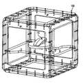
- FIG. 1 shows an exemplary calibration cube and sensor according to an exemplary embodiment of the present invention
- FIG. 2 depicts an exemplary cube holder A according to an exemplary embodiment of the present invention
- FIG. 3 depicts an exemplary cube holder B according to an exemplary embodiment of the present invention.
- FIG. 4 illustrates an exemplary rotation sequence according to an exemplary embodiment of the present invention.
- the exemplary embodiment described below uses Earth's magnetic field to calibrate a 3-D magnetometer, however the present invention can be used to calibrate other types of sensors in other ways, e.g., accelerometers.
- Exemplary embodiments of the present invention accurately orient the sensor in multiple positions to the vector field enabling the sensor to measure multiple readings of constant magnitude.
- the actual values measured by the sensor are known due to the fixed orientations achieved by the exemplary embodiments thereby allowing for a calibration of the device.
- a system includes a calibration cube 100 and a sensor under calibration 110 .
- the cube 100 can be accurately mounted in different orientations in a cube holder 200 (shown in FIG. 2 ).
- Another type of cube holder 300 is shown in FIG. 3 .
- the sensor under calibration 110 is located, in this example, at the center of the calibration cube 100 . Due to the design of the cube 100 and the holder 200 or 300 , the sensor will always be located in the same place in space regardless of the orientation of the cube. Keeping the sensor 110 in the same absolute position for all orientations of the cube 100 is desirable to minimize the effects of any divergence of the vector field.
- the sensor model determines the measured output of a sensor due to a known input.
- the different orientations determine the input vector measured by the sensor.
- a suitable calibration solution may be found that predicts the actual input given a measured sensor value.
- the cube holder should be oriented such that the vector will produce different readings for every orientation. For example, if the vector is normal to the face, then some orientations can provide duplicate information which could create a reduced data set and may not be sufficient to perform the calibration.
- the sensor under calibration 10 is mounted in the cube 100 .
- the cube 100 and hence the sensor under calibration, is accurately mounted in different orientations in a holder 200 or 300 .
- twenty-four (24) different cube orientations are achieved by placing the cube faces flush to the holder surface.
- the sensor readings are collected for each orientation by the supporting test equipment.
- the collected values may either be a single reading from each orientation, multiple readings from each orientation or a single aggregate value from each orientation.
- the operator rotates the cube according to a predetermined rotation sequence, an example of which is shown in FIG. 4 .
- the multiple readings are then processed through the sensor model to produce the sensor model calibration.
- the sensor model determines the minimum number of points required for calibration. Additional points beyond the minimum may help to reduce the calibration error.
- a s and m s are arbitrary scaling vectors for improved model convergence.
- M is the 3 ⁇ 1 vector of the sensor measurement.
- R is the 3 ⁇ 3 linear transformation matrix. Note that R includes rotation, scale, and skew.
- R I is the 3 ⁇ 3 rotation matrix that corresponds to the placement of the cube in the holder.
- H E is the actual value of the vector. Note that H E can be represented in spherical coordinates by:
- f is the transformation function
- the transformation function f is defined by the 3 ⁇ 3 calibration parameter matrix, K.
- Calibration can be performed according to this exemplary embodiment using a least squares fit between the left and right hand sides of equation (1) using a large scale field solver. The field solver finds appropriate values for R and K.
- the field solver can just as easily find ⁇ and ⁇ along with R and K. Therefore, the present invention can calibrate even when the vector direction of H E is not known. Each orientation with the collected values results in 3 equations.
- the model includes 20 total variables requiring a minimum of 7 points, however those skilled in the art will appreciate that other exemplary embodiments will have varying numbers of variables and use fewer or more minimum data points.
- the cube is in communications with a computer either via a wireline connection or a wireless connection.
- the computer takes the raw data from the cube 100 and processes the raw data into calibration information for the sensor 110 .
- the calibration information is then sent to sensor 110 .
- the sensor 110 is in communication with cube 100 .
- the cube 100 collects the raw data and transmits the raw data to the sensor 110 .
- the sensor 110 has an onboard processor capable of processing the raw data into the desired calibration information.
- the cube 100 can have a communications module (not shown) mounted on it for communications purposes.
- the cube holder may contain additional supports for additional cube orientations.
- Other embodiments of the present invention include supporting the cube 100 along an edge at an angle or supporting the cube 100 along a corner at an angle.
- Both cube holder 200 and cube holder 300 have provisions for mounting orientations beyond just the cube faces.
- the cube holder can still be designed such that the sensor is maintained in the same position regardless of orientation.
- the cube holder could also be designed to include any of the above mounting options in the same physical device.
- the exemplary embodiments described above operate by having a known sequence of R I .
- the present invention can be extended to include additional sensors to automatically determine the appropriate value for R I . With automatic R I determination, the system can recover from operator errors and resequence the collected values before determining the model parameters.
- these exemplary embodiments require no complicated mechanical design, no automated moving parts and are achievable at low-cost. These exemplary embodiments also require no external devices, such as a Helmholtz coil to create or manipulate the input vector field. These exemplary designs are also effective under vector fields with a gradient without additional calibration since the sensor under calibration always measures the field from the same location in space.
Abstract
Description
R I *H E =a s *R*f(M/m s) (1)
- HM*[sin(θ)*cos(φ), sin(θ)*sin(φ), cos(θ)] where HM is the magnitude of the vector.
Thus, in this exemplary embodiment, the transformation function f is defined by the 3×3 calibration parameter matrix, K. Calibration can be performed according to this exemplary embodiment using a least squares fit between the left and right hand sides of equation (1) using a large scale field solver. The field solver finds appropriate values for R and K. Note that the field solver can just as easily find θ and φ along with R and K. Therefore, the present invention can calibrate even when the vector direction of HE is not known. Each orientation with the collected values results in 3 equations. In the exemplary embodiment with HE calibration, the model includes 20 total variables requiring a minimum of 7 points, however those skilled in the art will appreciate that other exemplary embodiments will have varying numbers of variables and use fewer or more minimum data points.
Claims (25)
Priority Applications (1)
| Application Number | Priority Date | Filing Date | Title |
|---|---|---|---|
| US11/605,050 US7719261B2 (en) | 2005-11-28 | 2006-11-27 | Methods and systems for calibrating a sensor using a vector field |
Applications Claiming Priority (2)
| Application Number | Priority Date | Filing Date | Title |
|---|---|---|---|
| US74002105P | 2005-11-28 | 2005-11-28 | |
| US11/605,050 US7719261B2 (en) | 2005-11-28 | 2006-11-27 | Methods and systems for calibrating a sensor using a vector field |
Publications (2)
| Publication Number | Publication Date |
|---|---|
| US20070124097A1 US20070124097A1 (en) | 2007-05-31 |
| US7719261B2 true US7719261B2 (en) | 2010-05-18 |
Family
ID=38088610
Family Applications (1)
| Application Number | Title | Priority Date | Filing Date |
|---|---|---|---|
| US11/605,050 Expired - Fee Related US7719261B2 (en) | 2005-11-28 | 2006-11-27 | Methods and systems for calibrating a sensor using a vector field |
Country Status (1)
| Country | Link |
|---|---|
| US (1) | US7719261B2 (en) |
Cited By (9)
| Publication number | Priority date | Publication date | Assignee | Title |
|---|---|---|---|---|
| WO2013188776A1 (en) * | 2012-06-14 | 2013-12-19 | Yei Corporation | Determining and correcting error of positional vector-valued sensors using a fixed angle calibration process |
| US8963538B2 (en) | 2011-02-22 | 2015-02-24 | Freescale Semiconductor Inc. | Magnetometer test arrangement and method |
| US9030405B2 (en) | 2011-02-04 | 2015-05-12 | Invensense, Inc. | High fidelity remote controller device for digital living room |
| US9255799B2 (en) | 2012-06-14 | 2016-02-09 | Yost Labs Inc. | Determining and correcting error of positional vector-valued sensors using a fixed angle calibration process |
| US20180120406A1 (en) * | 2016-10-31 | 2018-05-03 | Senis Ag | Calibration tool for calibrating a magnetic sensor |
| CN109839610A (en) * | 2018-12-27 | 2019-06-04 | 中国计量科学研究院 | Helmholtz coil constant exchange calibration system and method based on orthogonality principle |
| US10883812B2 (en) | 2018-01-19 | 2021-01-05 | Ascension Technology Corporation | Calibrating a magnetic transmitter |
| US10948278B2 (en) | 2018-01-19 | 2021-03-16 | Ascension Technology Corporation | Calibrating a magnetic sensor |
| US11340311B2 (en) | 2019-04-16 | 2022-05-24 | Northern Digital Inc. | Determining position and orientation from a Helmholtz device |
Families Citing this family (9)
| Publication number | Priority date | Publication date | Assignee | Title |
|---|---|---|---|---|
| US7467536B2 (en) * | 2005-11-21 | 2008-12-23 | The United States Of America As Represented By The Administrator Of The National Aeronautics And Space Administration | Positioning system for single or multi-axis sensitive instrument calibration and calibration system for use therewith |
| US7826999B1 (en) | 2007-08-20 | 2010-11-02 | Pni Corporation | Magnetic tilt compensated heading compass with adaptive zoffset |
| US9952671B2 (en) * | 2010-10-12 | 2018-04-24 | Nokia Technologies Oy | Method and apparatus for determining motion |
| EP2447669A1 (en) * | 2010-10-26 | 2012-05-02 | Research In Motion Limited | System and method for calibrating a magnetometer using partial and full calibrations |
| US9052250B1 (en) | 2012-05-04 | 2015-06-09 | The United States Of America As Represented By The Administrator Of The National Aeronautics And Space Administration | Method of calibrating a force balance |
| JP2015102512A (en) * | 2013-11-27 | 2015-06-04 | 愛知製鋼株式会社 | Magnetic field generation device and offset calculation method |
| US20160041234A1 (en) | 2014-08-08 | 2016-02-11 | Halliburton Energy Services, Inc. | Calibration of sensitivity and axial orthogonality for magnetometers |
| US20160209235A1 (en) * | 2015-01-15 | 2016-07-21 | Jesus T. Fortu | Apparatus, method, and system for calibrating one or more motion sensors |
| DE102016001780A1 (en) * | 2016-02-08 | 2017-08-24 | Stefan von den Driesch | Cost-effective method of calibrating magnetic field sensors in a high-precision directional drill for early, reliable and timely hole definition and a high-precision directional drill for low-cost deep direction drilling |
Citations (2)
| Publication number | Priority date | Publication date | Assignee | Title |
|---|---|---|---|---|
| US6647352B1 (en) * | 1998-06-05 | 2003-11-11 | Crossbow Technology | Dynamic attitude measurement method and apparatus |
| US20060058961A1 (en) * | 2004-09-10 | 2006-03-16 | Honeywell International Inc. | Gas supported inertial sensor system and method |
-
2006
- 2006-11-27 US US11/605,050 patent/US7719261B2/en not_active Expired - Fee Related
Patent Citations (2)
| Publication number | Priority date | Publication date | Assignee | Title |
|---|---|---|---|---|
| US6647352B1 (en) * | 1998-06-05 | 2003-11-11 | Crossbow Technology | Dynamic attitude measurement method and apparatus |
| US20060058961A1 (en) * | 2004-09-10 | 2006-03-16 | Honeywell International Inc. | Gas supported inertial sensor system and method |
Cited By (14)
| Publication number | Priority date | Publication date | Assignee | Title |
|---|---|---|---|---|
| US9030405B2 (en) | 2011-02-04 | 2015-05-12 | Invensense, Inc. | High fidelity remote controller device for digital living room |
| US9046937B2 (en) | 2011-02-04 | 2015-06-02 | Invensense, Inc. | High fidelity remote controller device for digital living room |
| US9703397B2 (en) | 2011-02-04 | 2017-07-11 | Invensense, Inc. | High fidelity remote controller device for digital living room |
| US8963538B2 (en) | 2011-02-22 | 2015-02-24 | Freescale Semiconductor Inc. | Magnetometer test arrangement and method |
| WO2013188776A1 (en) * | 2012-06-14 | 2013-12-19 | Yei Corporation | Determining and correcting error of positional vector-valued sensors using a fixed angle calibration process |
| US9255799B2 (en) | 2012-06-14 | 2016-02-09 | Yost Labs Inc. | Determining and correcting error of positional vector-valued sensors using a fixed angle calibration process |
| US20180120406A1 (en) * | 2016-10-31 | 2018-05-03 | Senis Ag | Calibration tool for calibrating a magnetic sensor |
| US10393848B2 (en) * | 2016-10-31 | 2019-08-27 | Senis Ag | Calibration tool for calibrating a magnetic sensor |
| US10883812B2 (en) | 2018-01-19 | 2021-01-05 | Ascension Technology Corporation | Calibrating a magnetic transmitter |
| US10948278B2 (en) | 2018-01-19 | 2021-03-16 | Ascension Technology Corporation | Calibrating a magnetic sensor |
| US11604057B2 (en) | 2018-01-19 | 2023-03-14 | Northern Digital Inc. | Calibrating a magnetic transmitter |
| CN109839610A (en) * | 2018-12-27 | 2019-06-04 | 中国计量科学研究院 | Helmholtz coil constant exchange calibration system and method based on orthogonality principle |
| CN109839610B (en) * | 2018-12-27 | 2021-02-12 | 中国计量科学研究院 | Helmholtz coil constant alternating current calibration system and method based on orthogonality principle |
| US11340311B2 (en) | 2019-04-16 | 2022-05-24 | Northern Digital Inc. | Determining position and orientation from a Helmholtz device |
Also Published As
| Publication number | Publication date |
|---|---|
| US20070124097A1 (en) | 2007-05-31 |
Similar Documents
| Publication | Publication Date | Title |
|---|---|---|
| US7719261B2 (en) | Methods and systems for calibrating a sensor using a vector field | |
| US10782792B2 (en) | 3D pointing devices with orientation compensation and improved usability | |
| US10620726B2 (en) | 3D pointer mapping | |
| US7414611B2 (en) | 3D pointing devices with orientation compensation and improved usability | |
| EP2337016B1 (en) | Free space pointing devices with tilt compensation and improved usability | |
| US7489299B2 (en) | User interface devices and methods employing accelerometers | |
| US10120463B2 (en) | Determining forward pointing direction of a handheld device | |
| US20070113207A1 (en) | Methods and systems for gesture classification in 3D pointing devices | |
| WO2007089831A2 (en) | 3d pointing devices with keyboards |
Legal Events
| Date | Code | Title | Description |
|---|---|---|---|
| AS | Assignment |
Owner name: HILLCREST LABORATORIES, INC.,MARYLAND Free format text: ASSIGNMENT OF ASSIGNORS INTEREST;ASSIGNORS:GECK, FRIEDRICH;LIBERTY, MATTHEW G.;TURNER, MARK;REEL/FRAME:018598/0321 Effective date: 20061206 Owner name: HILLCREST LABORATORIES, INC., MARYLAND Free format text: ASSIGNMENT OF ASSIGNORS INTEREST;ASSIGNORS:GECK, FRIEDRICH;LIBERTY, MATTHEW G.;TURNER, MARK;REEL/FRAME:018598/0321 Effective date: 20061206 |
|
| STCF | Information on status: patent grant |
Free format text: PATENTED CASE |
|
| AS | Assignment |
Owner name: HERCULES TECHNOLOGY III, L.P., CALIFORNIA Free format text: SECURITY AGREEMENT;ASSIGNOR:HILLCREST LABORATORIES, INC.;REEL/FRAME:028023/0544 Effective date: 20120406 |
|
| FEPP | Fee payment procedure |
Free format text: PAT HOLDER NO LONGER CLAIMS SMALL ENTITY STATUS, ENTITY STATUS SET TO UNDISCOUNTED (ORIGINAL EVENT CODE: STOL); ENTITY STATUS OF PATENT OWNER: LARGE ENTITY |
|
| FPAY | Fee payment |
Year of fee payment: 4 |
|
| AS | Assignment |
Owner name: HILLCREST LABORATORIES, INC., MARYLAND Free format text: RELEASE BY SECURED PARTY;ASSIGNOR:HERCULES TECHNOLOGY III, L.P.;REEL/FRAME:035899/0239 Effective date: 20150611 |
|
| AS | Assignment |
Owner name: MULTIPLIER CAPITAL, LP, MARYLAND Free format text: SECURITY AGREEMENT;ASSIGNOR:HILLCREST LABORATORIES, INC.;REEL/FRAME:037963/0405 Effective date: 20141002 |
|
| AS | Assignment |
Owner name: IDHL HOLDINGS, INC., DELAWARE Free format text: ASSIGNMENT OF ASSIGNORS INTEREST;ASSIGNOR:HILLCREST LABORATORIES, INC.;REEL/FRAME:042747/0445 Effective date: 20161222 |
|
| AS | Assignment |
Owner name: HILLCREST LABORATORIES, INC., DELAWARE Free format text: RELEASE BY SECURED PARTY;ASSIGNOR:MULTIPLIER CAPITAL, LP;REEL/FRAME:043339/0214 Effective date: 20170606 |
|
| MAFP | Maintenance fee payment |
Free format text: PAYMENT OF MAINTENANCE FEE, 8TH YEAR, LARGE ENTITY (ORIGINAL EVENT CODE: M1552) Year of fee payment: 8 |
|
| FEPP | Fee payment procedure |
Free format text: MAINTENANCE FEE REMINDER MAILED (ORIGINAL EVENT CODE: REM.); ENTITY STATUS OF PATENT OWNER: LARGE ENTITY |
|
| LAPS | Lapse for failure to pay maintenance fees |
Free format text: PATENT EXPIRED FOR FAILURE TO PAY MAINTENANCE FEES (ORIGINAL EVENT CODE: EXP.); ENTITY STATUS OF PATENT OWNER: LARGE ENTITY |
|
| STCH | Information on status: patent discontinuation |
Free format text: PATENT EXPIRED DUE TO NONPAYMENT OF MAINTENANCE FEES UNDER 37 CFR 1.362 |
|
| STCH | Information on status: patent discontinuation |
Free format text: PATENT EXPIRED DUE TO NONPAYMENT OF MAINTENANCE FEES UNDER 37 CFR 1.362 |
|
| FP | Lapsed due to failure to pay maintenance fee |
Effective date: 20220518 |