US7722771B2 - Continuous processing and solids handling in near-critical and supercritical fluids - Google Patents
Continuous processing and solids handling in near-critical and supercritical fluids Download PDFInfo
- Publication number
- US7722771B2 US7722771B2 US11/103,673 US10367305A US7722771B2 US 7722771 B2 US7722771 B2 US 7722771B2 US 10367305 A US10367305 A US 10367305A US 7722771 B2 US7722771 B2 US 7722771B2
- Authority
- US
- United States
- Prior art keywords
- critical
- vessel
- fluid
- starting material
- supercritical fluid
- Prior art date
- Legal status (The legal status is an assumption and is not a legal conclusion. Google has not performed a legal analysis and makes no representation as to the accuracy of the status listed.)
- Expired - Fee Related, expires
Links
Images


Classifications
-
- B—PERFORMING OPERATIONS; TRANSPORTING
- B01—PHYSICAL OR CHEMICAL PROCESSES OR APPARATUS IN GENERAL
- B01D—SEPARATION
- B01D11/00—Solvent extraction
- B01D11/02—Solvent extraction of solids
- B01D11/0203—Solvent extraction of solids with a supercritical fluid
Definitions
- Supercritical fluids have gained wide acceptance in the past decade for their use in a number of processes. They are unique in the sense that density can be manipulated by simply changing pressure or temperature. Thus, all density-dependent properties are also varied. This makes supercritical fluids ideal candidates for extraction solvents. At a given set of conditions, a substance can be dissolved and extracted in the supercritical fluid. Once extracted, the extracted product can be separated from the supercritical fluid simply by modifying the thermodynamic properties of the fluid (changing temperature and/or pressure) or by a separating means such as an absorption column or an adsorption vessel. No further separation steps are necessary.
- Carbon dioxide is a popular supercritical fluid because it is nontoxic, inexpensive, and widely available. Another popular fluid that can be used is propane. Propane is also relatively inexpensive and can be used at low pressures.
- a wide variety of solids can be processed using supercritical fluids such as various vegetable seeds, food ingredients, herbs, botanicals, solids contaminated with toxic organic material or pharmaceutical materials.
- supercritical fluids such as various vegetable seeds, food ingredients, herbs, botanicals, solids contaminated with toxic organic material or pharmaceutical materials.
- One embodiment of the present invention comprises a method for introducing a solid starting material into a vessel containing a near-critical or supercritical fluid.
- the steps of this method embodiment comprise: (i) providing a loading zone; (ii) providing a restriction means between the loading zone and the vessel; (iii) loading the loading zone with the starting material; (iv) closing the loading zone to the environment; (v) equalizing the pressure in the loading zone with the vessel pressure; and (vi) transferring the starting material from the loading zone to the vessel through a mechanical conveying means.
- Another embodiment of the present invention comprises a method for removing raffinate from a vessel containing a near-critical or supercritical fluid into an unloading zone.
- This method comprises: (i) providing a vessel with a raffinate; (ii) providing an unloading zone; (iii) providing a barrier fluid in the unloading zone to collect the raffinate; and (iv) removing the barrier fluid and the raffinate.
- An additional embodiment of the present invention encompasses a method for the continuous processing of a starting material using a near-critical or supercritical fluid.
- Such method comprises: (i) loading a loading zone with the starting material; (ii) providing a vessel for treatment of the starting material; (iii) equalizing the pressure in the loading zone with the vessel pressure using the near-critical or supercritical fluid; (iv) introducing the starting material from the loading zone into the vessel under near-critical or supercritical conditions through a restriction means through a mechanical conveying means; (v) treating the starting material with the near-critical or supercritical fluid; and (vi) collecting raffinate in an unloading zone.
- Another embodiment of the present invention comprises an apparatus for introducing a starting material into a vessel containing a near-critical or supercritical fluid.
- This apparatus comprises: (i) a loading zone; (ii) a restriction means between the loading zone and the vessel for equalizing the pressure between the loading zone and the vessel; (iii) a mechanical conveying means for transferring the starting material from the loading zone to the vessel; and (iv) a restriction means between the loading zone and the vessel through which the starting material enters the vessel.
- Another embodiment of the present invention comprises an apparatus for removing raffinate from a vessel containing a near-critical or supercritical fluid into an unloading zone containing a barrier fluid in the unloading zone to collect the raffinate.
- Another embodiment of the present invention comprises an apparatus for the continuous processing of a starting material using a near-critical or supercritical fluid.
- This apparatus comprises: (i) a loading zone; (ii) a mechanical conveying means for introducing the starting material from the loading zone into a vessel for treating the starting material under near-critical or supercritical conditions; (iii) a restriction means through which the starting material enters the vessel; (iv) a pressure equalization means between the loading zone and the vessel; and (v) an unloading zone for collecting the raffinate.
- FIG. 1 is a schematic representation of one embodiment of the present invention for continuous processing and solids handling using a near-critical or supercritical fluid;
- FIG. 2 is a schematic representation of the loading zone used to transfer the starting material into the vessel.
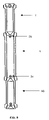
- FIG. 3 is a schematic representation of one embodiment of the present invention in which the loading zone, vessel and unloading zone are contained in separate units.
- One embodiment of the present invention provides a method and apparatus for continuous processing and solids handling in near-critical and supercritical fluids.
- a starting material is transferred into a loading zone.
- the starting material is fed from a storage area, through a restriction means to load the loading zone.
- This can be accomplished by any suitable propelling means, including but not limited to gravity, a conveyor or the addition of a fluid.
- suitable propelling means including but not limited to gravity, a conveyor or the addition of a fluid.
- the conveyor is a belt driver.
- the fluid may be the near-critical or supercritical fluid present in the vessel or a different fluid.
- the starting material is transferred to a vessel through a restriction means by a mechanical conveying means.
- This process may be performed in a continuous or semi-continuous manner.
- the pressure in the loading zone may be equalized to the pressure of the vessel. Pressure equalization is accomplished by directing the near-critical or supercritical fluid in the vessel into the loading zone through a restriction means.
- Possible restriction means include but are not limited to a ball valve, check valve, gate valve, rotary valve, plug valve, a sealing mechanism, or any other device that satisfies the criteria for the restriction means and the mechanical conveying means may be a hydraulic or pneumatic piston or any other device that satisfies the criteria for the mechanical conveying means.
- a hydraulic- or pneumatic-driven piston to load the starting material into the vessel provides several advantages.
- the material typically gets compacted, thus diminishing the amount of near-critical or supercritical fluid that can percolate into and through the material and extract any soluble substances.
- a hydraulic- or pneumatic-driven piston the starting material gets less compacted, allowing for the near-critical or supercritical fluid to percolate into and through the starting material and extract the soluble substances more easily.
- a hydraulic- or pneumatic-driven piston can be used for a wide variety of starting materials. Because some starting materials do not have the characteristics required, such as flowability or heaviness, to be transferred to the vessel by means of gravity, a mechanical conveying means has to be employed.
- a separate conveying means can be used within the vessel to control the transfer rate of the starting material through the vessel and thus, to control the contact time between the starting material and the near-critical or supercritical fluid.
- the separate conveying means within the vessel is controlled and may be driven from inside or outside of the vessel.
- the separate conveying means may be any device that serves the stated purpose.
- Some examples of possible separate conveying means include pneumatic, hydraulic, electric, magnetic, or a combination thereof.
- the near-critical or supercritical fluid to be used in some embodiments of the present invention process includes, but is not limited to, ethane, propane, carbon dioxide, nitrous oxide, butane, isobutene, sulfur hexafluoride, water, hydrochlorofluorocarbons, hydrofluorocarbons, alkanes, or a combination thereof.
- the preferred near-critical or supercritical fluid is carbon dioxide or propane.
- the near-critical or supercritical fluid treats the starting material. The treatment is selected from the group consisting of extraction, reaction, coating, absorption, adsorption, or a combination thereof.
- the temperature of the near-critical or supercritical fluid treatment is performed between 0° C. and 400° C. and pressure is between 10 bar and 1500 bar. In another embodiment of the present invention, more than one temperature zone is provided within the vessel.
- the raffinate continuously enters an unloading zone, which is located at the bottom of the vessel or as a separate unit connected to the vessel, through a restriction means.
- the term raffinate refers to any of the material that is left in the vessel after treatment.
- the unloading zone contains a barrier fluid. The presence of the barrier fluid allows for the raffinate to be separated from the near-critical or supercritical fluid due to the low solubility of the near-critical or supercritical fluid in the liquid.
- the barrier fluid is chosen such that it and the near or supercritical fluid are not substantially miscible with each other.
- the degree of miscibility is not a restriction in the way the invention is practiced.
- the barrier fluid may be selected from a group including water, alcohols, ethers, ketones, ionic liquids, any other fluid immiscible with the near-critical or supercritical fluid, or a combination thereof. It will be obvious to one skilled in the art that other barrier fluids may be used and the use of such other fluids is encompassed by the present invention.
- the raffinate is continuously removed from the vessel and collected.
- the barrier fluid is then recycled back to the vessel using a recirculation pump, which controls the barrier fluid level and keeps it constant.
- the raffinate is then removed from the barrier fluid using a hydro-cyclone or other separation means available in the art.
- the barrier fluid can be used to further treat substances in the raffinate that are soluble in the barrier fluid.
- the barrier fluid extraction is performed between 0° C. and 400° C. and the pressure is equal to the pressure in the vessel. This enables the extraction of non-polar or low polarity components using the near-critical or supercritical fluid and polar components using the barrier fluid, or the reverse in which polar components can be extracted in the near-critical or supercritical fluid and non-polar or low polarity components can be extracted in the barrier fluid.
- there are multiple heating zones in the vessel providing the flexibility of treating the starting material at constant temperature or at different temperatures. Such capability may facilitate fractionation of the starting material.
- the raffinate is collected in the unloading zone and continuously or semi-continuously removed from it using a separate mechanical conveying system such as screw press.
- a conveyor or screw system may be coupled with collection in a barrier fluid. Once the raffinate is collected in the barrier fluid, a conveyor or screw can be used to move the raffinate to a separation collection means, such as a hydro-cyclone. The barrier fluid is recycled back to the unloading zone.
- the near-critical or supercritical fluid containing any soluble substances leaves the vessel from the top.
- the soluble substances are then separated from the near-critical or supercritical fluid by modifying the pressure and/or temperature or by using external agents such as adsorption vessels or absorption columns.
- the soluble substances are then collected using a cyclone separator or other collection or separation means known in the art.
- the near-critical or supercritical fluid is recycled back to the vessel at subcritical or supercritical conditions.
- the near-critical or supercritical fluid containing any soluble substances can be fractionated by several methods, including, but not limited to, a temperature gradient, sequential depressurization, means for adsorption or absorption, or a combination thereof.
- the near-critical or supercritical fluid containing any soluble substances can be transferred to another column or vessel and undergo another treatment, such as a reaction.
- the reaction may be with another reactant or within the components present in the near-critical or supercritical fluid.
- the reaction may be of chemical, physical, biological, nuclear or enzymatic, or a combination thereof.
- the loading zone, vessel, and unloading zone are contained in one unit. Therefore, the transfer of the starting material from the loading zone to the vessel, treatment of the starting material in the vessel, and collection and/or removal of the raffinate can all be carried out in a single unit.
- the loading zone, vessel, and unloading zone are contained in separate units.
- the loading zone is in contact with the vessel through a restriction means, and the vessel is in contact with the unloading zone through a restriction means.
- restriction means There is no limitation to the axial orientation of any of the zones in the present invention.
- FIG. 1 illustrates one embodiment of the present invention for the continuous processing of solids using near-critical or supercritical fluids.
- a starting material is transferred to the loading zone ( 1 ) from a storage tank ( 2 ) through a restriction means ( 3 a ).
- the starting material is transferred into the vessel ( 4 ) through a restriction means ( 3 b ).
- Different restriction mechanisms such as a check valve, ball valve, rotary valve or seal, may be used, but there is no limitation on the restriction means.
- the restriction means may be driven from inside or outside of the loading zone ( 1 ).
- a mechanical conveying means ( 9 a ) such as a piston is used to transfer or facilitate the transfer of the starting material into the vessel ( 4 ).
- An additional means of facilitating the transfer of the starting material to the vessel ( 4 ) is to equalize the pressure in the loading zone ( 1 ) through a restrictions means ( 3 e ) with the near-critical or supercritical fluid itself or another fluid to the pressure in the vessel ( 4 ).
- a mechanical conveying means ( 9 b ) located inside the vessel ( 4 ) is used to control the transfer rate of the starting material through the vessel ( 4 ).
- the mechanical conveying means ( 9 b ) may extend the entire length of the vessel ( 4 ) or may be used in only certain sections, such as from between the restriction means ( 3 b ) to a barrier fluid ( 5 ) in the unloading zone ( 10 ).
- the mechanical conveying means ( 9 b ) can be of pneumatic, electric, magnetic or hydraulic type and may be driven from inside or outside of the vessel ( 4 ). In another embodiment, a screw press may be used to accomplish the same effect.
- the raffinate moves through a restriction means ( 3 c ) into the barrier fluid ( 5 ) at the bottom of the unloading zone ( 10 ).
- the raffinate which is continuously removed from the unloading zone ( 10 ) through a restriction means ( 3 d ), is then separated from the barrier fluid ( 5 ) using a separating means ( 7 a ).
- a hydrocyclone is used as the separating means ( 7 a ).
- various separation means known in the art can also be used.
- the barrier fluid ( 5 ) is recycled back to the unloading zone ( 10 ) using a recirculation means ( 6 ).
- the near-critical or supercritical fluid containing one or more soluble substances leaves the vessel ( 4 ) and the soluble substances are separated from the near-critical or supercritical fluid using a separating means ( 7 b ). Separation of the soluble substances from the near-critical or supercritical fluid can be accomplished by various methods. Manipulation of thermodynamic properties such as temperature and pressure, addition of external agents, membrane separation, adsorption, absorption and other techniques known in the art may be used for this purpose.
- the soluble substances can be recovered in the separating means ( 7 b ) and the near-critical or supercritical fluid can be recycled back to the vessel ( 4 ).
- a screw press can be used to remove the raffinate from the vessel ( 4 ) with or without the use of a barrier fluid.
- FIG. 2 illustrates one embodiment of the loading zone ( 1 ) of the present invention.
- a starting material is transferred into the loading zone ( 1 ) from a storage tank ( 2 ) through a restriction means ( 3 a ).
- the starting material enters an enclosed space ( 8 ) in the loading zone ( 1 ) beneath a mechanical conveying means ( 9 a ).
- a restriction means ( 3 b ) is in a position such that the enclosed space ( 8 ) is closed off from the vessel ( 4 ).
- the mechanical conveying means ( 9 a ) is then moved to a position to close off the enclosed space ( 8 ) from the point of entry of the starting material into the loading zone ( 1 ).
- a restriction means ( 3 e ) is then opened to allow entry of the near-critical or supercritical fluid in the vessel ( 4 ) into the enclosed space ( 8 ), which results in pressure equalization between the vessel ( 4 ) and the enclosed space ( 8 ).
- the restriction means ( 3 b ) is adjusted to allow entry of the starting material into the vessel ( 4 ).
- the mechanical conveying means ( 9 a ) is then lowered to facilitate transfer of the starting material into the vessel ( 4 ) and to return the near-critical or supercritical fluid to the vessel ( 4 ). Any residual near-critical or supercritical fluid that is left in the enclosed space ( 8 ) can be vented to the atmosphere.
- FIG. 3 illustrates an embodiment of the present invention in which the loading zone ( 1 ), vessel ( 4 ), and unloading zone ( 10 ) are each contained in separate units.
- the loading zone ( 1 ) is in contact with the vessel ( 4 ) through a restriction means ( 3 b ), and the vessel ( 4 ) is in contact with the unloading zone ( 10 ) through a restriction means ( 3 c ).
- restriction means 3 b
- restriction means 3 c
Abstract
Description
Claims (34)
Priority Applications (2)
| Application Number | Priority Date | Filing Date | Title |
|---|---|---|---|
| US11/103,673 US7722771B2 (en) | 2004-04-12 | 2005-04-12 | Continuous processing and solids handling in near-critical and supercritical fluids |
| US12/787,089 US8460550B2 (en) | 2004-04-12 | 2010-05-25 | Continuous processing and solids handling in near-critical and supercritical fluids |
Applications Claiming Priority (2)
| Application Number | Priority Date | Filing Date | Title |
|---|---|---|---|
| US56130504P | 2004-04-12 | 2004-04-12 | |
| US11/103,673 US7722771B2 (en) | 2004-04-12 | 2005-04-12 | Continuous processing and solids handling in near-critical and supercritical fluids |
Related Child Applications (1)
| Application Number | Title | Priority Date | Filing Date |
|---|---|---|---|
| US12/787,089 Continuation-In-Part US8460550B2 (en) | 2004-04-12 | 2010-05-25 | Continuous processing and solids handling in near-critical and supercritical fluids |
Publications (2)
| Publication Number | Publication Date |
|---|---|
| US20050283010A1 US20050283010A1 (en) | 2005-12-22 |
| US7722771B2 true US7722771B2 (en) | 2010-05-25 |
Family
ID=34965985
Family Applications (1)
| Application Number | Title | Priority Date | Filing Date |
|---|---|---|---|
| US11/103,673 Expired - Fee Related US7722771B2 (en) | 2004-04-12 | 2005-04-12 | Continuous processing and solids handling in near-critical and supercritical fluids |
Country Status (3)
| Country | Link |
|---|---|
| US (1) | US7722771B2 (en) |
| CA (1) | CA2562505A1 (en) |
| WO (1) | WO2005099853A1 (en) |
Cited By (4)
| Publication number | Priority date | Publication date | Assignee | Title |
|---|---|---|---|---|
| US20060197053A1 (en) * | 2005-02-04 | 2006-09-07 | Shiflett Mark B | Absorption cycle utilizing ionic liquid as working fluid |
| US20070144186A1 (en) * | 2005-12-14 | 2007-06-28 | Shiflett Mark B | Absorption cycle utilizing ionic liquids and water as working fluids |
| US20100267976A1 (en) * | 2004-04-12 | 2010-10-21 | Thar Process, Inc. | Continuous processing and solids handling in near-critical and supercritical fluids |
| US8293018B2 (en) | 2010-10-22 | 2012-10-23 | Bepex International, Llc | System and method for the continuous treatment of solids at non-atmospheric pressure |
Families Citing this family (6)
| Publication number | Priority date | Publication date | Assignee | Title |
|---|---|---|---|---|
| FR2803538B1 (en) * | 1999-12-15 | 2002-06-07 | Separex Sa | METHOD AND DEVICE FOR CAPTURING FINE PARTICLES BY PERCOLATION IN A BED OF GRANULES |
| FR2874513B1 (en) * | 2004-08-25 | 2006-11-03 | Commissariat Energie Atomique | DIPOSITIVE AND PLANT FOR INJECTING PARTICULATE MATERIALS IN AN ENCLOSURE AND ASSOCIATED METHOD. |
| US8048304B2 (en) * | 2007-12-27 | 2011-11-01 | Dynasep Llc | Solvent extraction and recovery |
| DE102008021629B4 (en) * | 2008-04-25 | 2017-09-14 | Technische Werke Ludwigshafen Ag | Apparatus for the production of raw materials, fuels and fuels from organic substances |
| WO2011155997A2 (en) * | 2010-06-09 | 2011-12-15 | Thar Process, Inc. | Method of cleaning a material |
| CA3094044C (en) * | 2018-03-16 | 2023-07-18 | Ricoh Company, Ltd. | Method of producing extract and extraction residue of biological material, extract, and extraction residue |
Citations (33)
| Publication number | Priority date | Publication date | Assignee | Title |
|---|---|---|---|---|
| GB166993A (en) | 1920-04-28 | 1921-07-28 | John Isaac Thornycroft | Improvements in or relating to apparatus for the extraction of juice from vegetable substances |
| FR637386A (en) | 1926-07-10 | 1928-04-28 | Ig Farbenindustrie Ag | Method for introducing substances into reaction vessels under pressure |
| GB418107A (en) | 1934-03-09 | 1934-10-18 | Aage Nyrop | Process and device for extracting fats and oils from animal and vegetable material |
| US2281865A (en) * | 1935-03-22 | 1942-05-05 | Shell Dev | Process for separating high molecular mixtures |
| US2338606A (en) | 1941-09-30 | 1944-01-04 | Standard Oil Co | Transferring subdivided solids |
| US4094651A (en) | 1976-05-06 | 1978-06-13 | Donath Ernest E | Process for pseudohydrostatic feeding of solids into a reactor |
| US4218222A (en) | 1978-09-07 | 1980-08-19 | Texaco Inc. | Method of charging solids into coal gasification reactor |
| US4271754A (en) | 1977-11-19 | 1981-06-09 | Fried. Krupp Gmbh | Method of and apparatus for pressing of liquids from solid materials |
| US4357865A (en) | 1979-04-18 | 1982-11-09 | Fried. Krupp Gesellschaft Mit Beschrankter Haftung | Apparatus for the recovery of oil from oil-bearing vegetable matter |
| US4397657A (en) | 1982-04-19 | 1983-08-09 | Allis-Chalmers Corporation | Gas lock system charging particles into a pressurized gasification reactor |
| US4415336A (en) | 1981-06-11 | 1983-11-15 | Standard Oil Company (Indiana) | Method and apparatus for continuous pumping of compressible solids against high pressures |
| EP0156374A2 (en) | 1984-03-30 | 1985-10-02 | Lucas Meyer GmbH & Co | Process for the preparation of lecithine, by preference the continuous preparation of pure lecithine (oil removed) |
| US4675133A (en) | 1983-06-25 | 1987-06-23 | Fried. Krupp Gesellschaft Mit Beschrankter Haftung | Process for apparatus for the recovery of fats and oils |
| US4783010A (en) | 1981-07-03 | 1988-11-08 | Creusot-Loire | Method and device for pulverizing a solid fuel material |
| EP0338940A2 (en) | 1988-04-22 | 1989-10-25 | Crown Iron Works Company | Method of conditioning oil seeds and similar materials |
| JPH0372939A (en) | 1989-08-11 | 1991-03-28 | Kobe Steel Ltd | Apparatus for supplying and delivering material to be transported |
| US5041245A (en) | 1989-03-10 | 1991-08-20 | Bioseparations, Inc. | Continuous extraction of oil-containing vegetable matter with pressurized normally gaseous solvent |
| DE4216295A1 (en) | 1992-05-16 | 1993-11-18 | Lentz Harro | Cylinder for quasi-continuous technical-chemical production of solid and paste products - is subdivided into multiple chambers by single piston |
| US5411715A (en) | 1992-06-09 | 1995-05-02 | Eastman Kodak Company | Apparatus for preparing aqueous amorphous particle dispersions of high-melting microcrystalline solids |
| US5630911A (en) | 1995-01-18 | 1997-05-20 | Crown Iron Works Company | Apparatus for continuous removal of a solvent or other liquid from solid particles or granules |
| US5707673A (en) * | 1996-10-04 | 1998-01-13 | Prewell Industries, L.L.C. | Process for extracting lipids and organics from animal and plant matter or organics-containing waste streams |
| US6013304A (en) | 1996-12-13 | 2000-01-11 | Kalamazoo Holdings, Inc. | High temperature countercurrent solvent extraction of herb or spice solids |
| EP1000984A1 (en) | 1998-11-12 | 2000-05-17 | Dow Corning Corporation | Method for densifying particulate silica |
| EP1004245A2 (en) | 1998-11-27 | 2000-05-31 | Krupp Uhde GmbH | Process for recovering in particular lecithin from dried egg |
| JP2001046857A (en) | 1999-08-09 | 2001-02-20 | Japan Organo Co Ltd | Solid reed-in apparatus and container equipped with solid discharge apparatus |
| US6262285B1 (en) | 1999-06-24 | 2001-07-17 | Crown Iron Works Company | Process for dry synthesis and continuous separation of a fatty acid methyl ester reaction product |
| US6279250B1 (en) | 1999-09-07 | 2001-08-28 | Crown Iron Works Company | Apparatus for enhanced solvent recovery from solvent extracted material |
| JP2002126490A (en) | 2000-10-20 | 2002-05-08 | Japan Organo Co Ltd | Vessel having solid feeder and solid discharger |
| US20020134704A1 (en) | 2001-03-22 | 2002-09-26 | Mitchell Allen R. | Process and system for continuously extracting oil from solid or liquid oil bearing material |
| US6509051B1 (en) | 2000-03-03 | 2003-01-21 | Crown Iron Works Company | Process for removing residual solvent from solids |
| US20030072867A1 (en) | 2001-10-15 | 2003-04-17 | Crown Iron Works Company | Two stage apparatus for desolventizing food grain meal |
| US6749752B2 (en) * | 2001-03-08 | 2004-06-15 | Cocotech, Inc. | System for removing oil from foodstuffs using a membrane filter |
| US20040225148A1 (en) | 2001-08-29 | 2004-11-11 | Mitsubishi Chemical Corporation | Process for the preparation of aromatic dicarboxylic acids |
-
2005
- 2005-04-12 WO PCT/US2005/012260 patent/WO2005099853A1/en active Application Filing
- 2005-04-12 CA CA002562505A patent/CA2562505A1/en not_active Abandoned
- 2005-04-12 US US11/103,673 patent/US7722771B2/en not_active Expired - Fee Related
Patent Citations (34)
| Publication number | Priority date | Publication date | Assignee | Title |
|---|---|---|---|---|
| GB166993A (en) | 1920-04-28 | 1921-07-28 | John Isaac Thornycroft | Improvements in or relating to apparatus for the extraction of juice from vegetable substances |
| FR637386A (en) | 1926-07-10 | 1928-04-28 | Ig Farbenindustrie Ag | Method for introducing substances into reaction vessels under pressure |
| GB418107A (en) | 1934-03-09 | 1934-10-18 | Aage Nyrop | Process and device for extracting fats and oils from animal and vegetable material |
| US2281865A (en) * | 1935-03-22 | 1942-05-05 | Shell Dev | Process for separating high molecular mixtures |
| US2338606A (en) | 1941-09-30 | 1944-01-04 | Standard Oil Co | Transferring subdivided solids |
| US4094651A (en) | 1976-05-06 | 1978-06-13 | Donath Ernest E | Process for pseudohydrostatic feeding of solids into a reactor |
| US4271754A (en) | 1977-11-19 | 1981-06-09 | Fried. Krupp Gmbh | Method of and apparatus for pressing of liquids from solid materials |
| US4218222A (en) | 1978-09-07 | 1980-08-19 | Texaco Inc. | Method of charging solids into coal gasification reactor |
| US4357865A (en) | 1979-04-18 | 1982-11-09 | Fried. Krupp Gesellschaft Mit Beschrankter Haftung | Apparatus for the recovery of oil from oil-bearing vegetable matter |
| US4467713A (en) | 1979-04-18 | 1984-08-28 | Fried. Krupp Gesellschaft Mit Beschrankter Haftung | Method of recovering oil from oil-bearing vegetable matter |
| US4415336A (en) | 1981-06-11 | 1983-11-15 | Standard Oil Company (Indiana) | Method and apparatus for continuous pumping of compressible solids against high pressures |
| US4783010A (en) | 1981-07-03 | 1988-11-08 | Creusot-Loire | Method and device for pulverizing a solid fuel material |
| US4397657A (en) | 1982-04-19 | 1983-08-09 | Allis-Chalmers Corporation | Gas lock system charging particles into a pressurized gasification reactor |
| US4675133A (en) | 1983-06-25 | 1987-06-23 | Fried. Krupp Gesellschaft Mit Beschrankter Haftung | Process for apparatus for the recovery of fats and oils |
| EP0156374A2 (en) | 1984-03-30 | 1985-10-02 | Lucas Meyer GmbH & Co | Process for the preparation of lecithine, by preference the continuous preparation of pure lecithine (oil removed) |
| EP0338940A2 (en) | 1988-04-22 | 1989-10-25 | Crown Iron Works Company | Method of conditioning oil seeds and similar materials |
| US5041245A (en) | 1989-03-10 | 1991-08-20 | Bioseparations, Inc. | Continuous extraction of oil-containing vegetable matter with pressurized normally gaseous solvent |
| JPH0372939A (en) | 1989-08-11 | 1991-03-28 | Kobe Steel Ltd | Apparatus for supplying and delivering material to be transported |
| DE4216295A1 (en) | 1992-05-16 | 1993-11-18 | Lentz Harro | Cylinder for quasi-continuous technical-chemical production of solid and paste products - is subdivided into multiple chambers by single piston |
| US5411715A (en) | 1992-06-09 | 1995-05-02 | Eastman Kodak Company | Apparatus for preparing aqueous amorphous particle dispersions of high-melting microcrystalline solids |
| US5630911A (en) | 1995-01-18 | 1997-05-20 | Crown Iron Works Company | Apparatus for continuous removal of a solvent or other liquid from solid particles or granules |
| US5707673A (en) * | 1996-10-04 | 1998-01-13 | Prewell Industries, L.L.C. | Process for extracting lipids and organics from animal and plant matter or organics-containing waste streams |
| US6013304A (en) | 1996-12-13 | 2000-01-11 | Kalamazoo Holdings, Inc. | High temperature countercurrent solvent extraction of herb or spice solids |
| EP1000984A1 (en) | 1998-11-12 | 2000-05-17 | Dow Corning Corporation | Method for densifying particulate silica |
| EP1004245A2 (en) | 1998-11-27 | 2000-05-31 | Krupp Uhde GmbH | Process for recovering in particular lecithin from dried egg |
| US6262285B1 (en) | 1999-06-24 | 2001-07-17 | Crown Iron Works Company | Process for dry synthesis and continuous separation of a fatty acid methyl ester reaction product |
| JP2001046857A (en) | 1999-08-09 | 2001-02-20 | Japan Organo Co Ltd | Solid reed-in apparatus and container equipped with solid discharge apparatus |
| US6279250B1 (en) | 1999-09-07 | 2001-08-28 | Crown Iron Works Company | Apparatus for enhanced solvent recovery from solvent extracted material |
| US6509051B1 (en) | 2000-03-03 | 2003-01-21 | Crown Iron Works Company | Process for removing residual solvent from solids |
| JP2002126490A (en) | 2000-10-20 | 2002-05-08 | Japan Organo Co Ltd | Vessel having solid feeder and solid discharger |
| US6749752B2 (en) * | 2001-03-08 | 2004-06-15 | Cocotech, Inc. | System for removing oil from foodstuffs using a membrane filter |
| US20020134704A1 (en) | 2001-03-22 | 2002-09-26 | Mitchell Allen R. | Process and system for continuously extracting oil from solid or liquid oil bearing material |
| US20040225148A1 (en) | 2001-08-29 | 2004-11-11 | Mitsubishi Chemical Corporation | Process for the preparation of aromatic dicarboxylic acids |
| US20030072867A1 (en) | 2001-10-15 | 2003-04-17 | Crown Iron Works Company | Two stage apparatus for desolventizing food grain meal |
Non-Patent Citations (1)
| Title |
|---|
| Recente ontwikkelingen op het gebied van superkritische extractie, Feb. 1989, The Netherlands. |
Cited By (8)
| Publication number | Priority date | Publication date | Assignee | Title |
|---|---|---|---|---|
| US20100267976A1 (en) * | 2004-04-12 | 2010-10-21 | Thar Process, Inc. | Continuous processing and solids handling in near-critical and supercritical fluids |
| US8460550B2 (en) * | 2004-04-12 | 2013-06-11 | Thar Process, Inc. | Continuous processing and solids handling in near-critical and supercritical fluids |
| US20060197053A1 (en) * | 2005-02-04 | 2006-09-07 | Shiflett Mark B | Absorption cycle utilizing ionic liquid as working fluid |
| US8715521B2 (en) | 2005-02-04 | 2014-05-06 | E I Du Pont De Nemours And Company | Absorption cycle utilizing ionic liquid as working fluid |
| US20070144186A1 (en) * | 2005-12-14 | 2007-06-28 | Shiflett Mark B | Absorption cycle utilizing ionic liquids and water as working fluids |
| US8506839B2 (en) * | 2005-12-14 | 2013-08-13 | E I Du Pont De Nemours And Company | Absorption cycle utilizing ionic liquids and water as working fluids |
| US8293018B2 (en) | 2010-10-22 | 2012-10-23 | Bepex International, Llc | System and method for the continuous treatment of solids at non-atmospheric pressure |
| US9055764B2 (en) | 2010-10-22 | 2015-06-16 | Bepex International, Llc | System and method for the continuous treatment of solids at non-atmospheric pressure |
Also Published As
| Publication number | Publication date |
|---|---|
| WO2005099853A1 (en) | 2005-10-27 |
| US20050283010A1 (en) | 2005-12-22 |
| CA2562505A1 (en) | 2005-10-27 |
Similar Documents
| Publication | Publication Date | Title |
|---|---|---|
| US7722771B2 (en) | Continuous processing and solids handling in near-critical and supercritical fluids | |
| EP0941140B1 (en) | Process for fluid/dense gas extraction under enhanced solubility conditions | |
| Pronyk et al. | Design and scale-up of pressurized fluid extractors for food and bioproducts | |
| Duba et al. | Extraction of polyphenols from grape skins and defatted grape seeds using subcritical water: Experiments and modeling | |
| Kassing et al. | A new approach for process development of plant‐based extraction processes | |
| EP2391698B1 (en) | Apparatus and method for oil and fat extraction | |
| FR2478643A1 (en) | PROCESS FOR OBTAINING PURE LECITHIN THAT CAN BE USED DIRECTLY FOR PHYSIOLOGICAL PURPOSES | |
| Del Valle et al. | Extraction kinetics of pre-pelletized Jalapeño peppers with supercritical CO2 | |
| US8460550B2 (en) | Continuous processing and solids handling in near-critical and supercritical fluids | |
| US20220072447A1 (en) | Device and method for the continuous high-pressure treatment of bulk material and use thereof | |
| US20220235289A1 (en) | Recirculating high pressure lipid (hpl) extractor, infuser and bonder, and system and method of use thereof | |
| Putra et al. | Diffusivity optimization of supercritical carbon dioxide extraction with co-solvent-ethanol from peanut skin | |
| US8801941B2 (en) | Method of removing oil from a mixture of tool steel swarf granular material and oil | |
| Priego-Capote | Solid–liquid extraction techniques | |
| CN101006022B (en) | Method and apparatus for pretreatment of polymeric materials | |
| Mrkonjić et al. | Valorization of wild thyme (Thymus serpyllum L.) herbal dust by supercritical fluid extraction–Experiments and modeling | |
| Acevedo-Correa et al. | Effect of the process parameters on the oil extraction yield during supercritical fluid extraction from grape seed | |
| Pfennig et al. | Extraction technology | |
| US2112805A (en) | Process for extracting oils and fats from materials containing the same | |
| JP2001340831A (en) | Method and apparatus for continuous treatment by using supercritical water | |
| US20220364015A1 (en) | Process for extraction of nutraceutical compounds from microalgae by using co2 in supercritical conditions | |
| Chaitanya et al. | Supercritical fluid extraction of functional ingredients from plants: A Review | |
| Goto et al. | Supercritical carbon dioxide extraction of carotenoids from carrots | |
| Voutsas | 7 Supercritical Fluid | |
| KR100769704B1 (en) | Sesame oil containing high content of tocopherol produced by using super critical fluid and process for production thereof |
Legal Events
| Date | Code | Title | Description |
|---|---|---|---|
| AS | Assignment |
Owner name: THAR TECHNOLOGIES, INC.,PENNSYLVANIA Free format text: ASSIGNMENT OF ASSIGNORS INTEREST;ASSIGNORS:CHORDIA, LALIT;DESAI, BHISHMAKUMAR;KEGLER, ANDREW;AND OTHERS;SIGNING DATES FROM 20050819 TO 20050824;REEL/FRAME:016916/0880 Owner name: THAR TECHNOLOGIES, INC.,PENNSYLVANIA Free format text: ASSIGNMENT OF ASSIGNORS INTEREST;ASSIGNORS:CHORDIA, LALIT;DESAI, BHISHMAKUMAR;KEGLER, ANDREW;AND OTHERS;SIGNING DATES FROM 20050819 TO 20050824;REEL/FRAME:016932/0788 Owner name: THAR TECHNOLOGIES, INC., PENNSYLVANIA Free format text: ASSIGNMENT OF ASSIGNORS INTEREST;ASSIGNORS:CHORDIA, LALIT;DESAI, BHISHMAKUMAR;KEGLER, ANDREW;AND OTHERS;REEL/FRAME:016932/0788;SIGNING DATES FROM 20050819 TO 20050824 Owner name: THAR TECHNOLOGIES, INC., PENNSYLVANIA Free format text: ASSIGNMENT OF ASSIGNORS INTEREST;ASSIGNORS:CHORDIA, LALIT;DESAI, BHISHMAKUMAR;KEGLER, ANDREW;AND OTHERS;REEL/FRAME:016916/0880;SIGNING DATES FROM 20050819 TO 20050824 |
|
| AS | Assignment |
Owner name: THAR PROCESS, INC., PENNSYLVANIA Free format text: ASSIGNMENT OF ASSIGNORS INTEREST;ASSIGNOR:THAR TECHNOLOGIES, INC.;REEL/FRAME:023720/0191 Effective date: 20091229 Owner name: THAR PROCESS, INC.,PENNSYLVANIA Free format text: ASSIGNMENT OF ASSIGNORS INTEREST;ASSIGNOR:THAR TECHNOLOGIES, INC.;REEL/FRAME:023720/0191 Effective date: 20091229 |
|
| FPAY | Fee payment |
Year of fee payment: 4 |
|
| FEPP | Fee payment procedure |
Free format text: MAINTENANCE FEE REMINDER MAILED (ORIGINAL EVENT CODE: REM.) |
|
| LAPS | Lapse for failure to pay maintenance fees |
Free format text: PATENT EXPIRED FOR FAILURE TO PAY MAINTENANCE FEES (ORIGINAL EVENT CODE: EXP.) |
|
| STCH | Information on status: patent discontinuation |
Free format text: PATENT EXPIRED DUE TO NONPAYMENT OF MAINTENANCE FEES UNDER 37 CFR 1.362 |
|
| FP | Lapsed due to failure to pay maintenance fee |
Effective date: 20180525 |