US7724348B2 - Exposure apparatus and method, and device manufacturing method - Google Patents

Exposure apparatus and method, and device manufacturing method Download PDF

Info

Publication number
US7724348B2
US7724348B2 US11/614,416 US61441606A US7724348B2 US 7724348 B2 US7724348 B2 US 7724348B2 US 61441606 A US61441606 A US 61441606A US 7724348 B2 US7724348 B2 US 7724348B2
Authority
US
United States
Prior art keywords
vacuum container
amount
exposure
water vapor
exposure light
Prior art date
Legal status (The legal status is an assumption and is not a legal conclusion. Google has not performed a legal analysis and makes no representation as to the accuracy of the status listed.)
Expired - Fee Related, expires
Application number
US11/614,416
Other versions
US20070097342A1 (en
Inventor
Yoshio Gomei
Hiromitsu Takase
Shigeru Terashima
Current Assignee (The listed assignees may be inaccurate. Google has not performed a legal analysis and makes no representation or warranty as to the accuracy of the list.)
Canon Inc
Original Assignee
Canon Inc
Priority date (The priority date is an assumption and is not a legal conclusion. Google has not performed a legal analysis and makes no representation as to the accuracy of the date listed.)
Filing date
Publication date
Application filed by Canon Inc filed Critical Canon Inc
Assigned to CANON KABUSHIKI KAISHA reassignment CANON KABUSHIKI KAISHA ASSIGNMENT OF ASSIGNORS INTEREST (SEE DOCUMENT FOR DETAILS). Assignors: TERASHIMA, SHIGERU, GOMEI, YOSHIO, TAKASE, HIROMITSU
Publication of US20070097342A1 publication Critical patent/US20070097342A1/en
Application granted granted Critical
Publication of US7724348B2 publication Critical patent/US7724348B2/en
Expired - Fee Related legal-status Critical Current
Adjusted expiration legal-status Critical

Links

Images

Classifications

    • GPHYSICS
    • G03PHOTOGRAPHY; CINEMATOGRAPHY; ANALOGOUS TECHNIQUES USING WAVES OTHER THAN OPTICAL WAVES; ELECTROGRAPHY; HOLOGRAPHY
    • G03FPHOTOMECHANICAL PRODUCTION OF TEXTURED OR PATTERNED SURFACES, e.g. FOR PRINTING, FOR PROCESSING OF SEMICONDUCTOR DEVICES; MATERIALS THEREFOR; ORIGINALS THEREFOR; APPARATUS SPECIALLY ADAPTED THEREFOR
    • G03F7/00Photomechanical, e.g. photolithographic, production of textured or patterned surfaces, e.g. printing surfaces; Materials therefor, e.g. comprising photoresists; Apparatus specially adapted therefor
    • G03F7/70Microphotolithographic exposure; Apparatus therefor
    • G03F7/708Construction of apparatus, e.g. environment aspects, hygiene aspects or materials
    • G03F7/7095Materials, e.g. materials for housing, stage or other support having particular properties, e.g. weight, strength, conductivity, thermal expansion coefficient
    • G03F7/70958Optical materials or coatings, e.g. with particular transmittance, reflectance or anti-reflection properties
    • GPHYSICS
    • G03PHOTOGRAPHY; CINEMATOGRAPHY; ANALOGOUS TECHNIQUES USING WAVES OTHER THAN OPTICAL WAVES; ELECTROGRAPHY; HOLOGRAPHY
    • G03FPHOTOMECHANICAL PRODUCTION OF TEXTURED OR PATTERNED SURFACES, e.g. FOR PRINTING, FOR PROCESSING OF SEMICONDUCTOR DEVICES; MATERIALS THEREFOR; ORIGINALS THEREFOR; APPARATUS SPECIALLY ADAPTED THEREFOR
    • G03F7/00Photomechanical, e.g. photolithographic, production of textured or patterned surfaces, e.g. printing surfaces; Materials therefor, e.g. comprising photoresists; Apparatus specially adapted therefor
    • G03F7/70Microphotolithographic exposure; Apparatus therefor
    • G03F7/708Construction of apparatus, e.g. environment aspects, hygiene aspects or materials
    • G03F7/70808Construction details, e.g. housing, load-lock, seals or windows for passing light in or out of apparatus
    • G03F7/70841Constructional issues related to vacuum environment, e.g. load-lock chamber
    • GPHYSICS
    • G03PHOTOGRAPHY; CINEMATOGRAPHY; ANALOGOUS TECHNIQUES USING WAVES OTHER THAN OPTICAL WAVES; ELECTROGRAPHY; HOLOGRAPHY
    • G03FPHOTOMECHANICAL PRODUCTION OF TEXTURED OR PATTERNED SURFACES, e.g. FOR PRINTING, FOR PROCESSING OF SEMICONDUCTOR DEVICES; MATERIALS THEREFOR; ORIGINALS THEREFOR; APPARATUS SPECIALLY ADAPTED THEREFOR
    • G03F7/00Photomechanical, e.g. photolithographic, production of textured or patterned surfaces, e.g. printing surfaces; Materials therefor, e.g. comprising photoresists; Apparatus specially adapted therefor
    • G03F7/70Microphotolithographic exposure; Apparatus therefor
    • G03F7/708Construction of apparatus, e.g. environment aspects, hygiene aspects or materials
    • G03F7/70908Hygiene, e.g. preventing apparatus pollution, mitigating effect of pollution or removing pollutants from apparatus
    • G03F7/70916Pollution mitigation, i.e. mitigating effect of contamination or debris, e.g. foil traps
    • GPHYSICS
    • G03PHOTOGRAPHY; CINEMATOGRAPHY; ANALOGOUS TECHNIQUES USING WAVES OTHER THAN OPTICAL WAVES; ELECTROGRAPHY; HOLOGRAPHY
    • G03FPHOTOMECHANICAL PRODUCTION OF TEXTURED OR PATTERNED SURFACES, e.g. FOR PRINTING, FOR PROCESSING OF SEMICONDUCTOR DEVICES; MATERIALS THEREFOR; ORIGINALS THEREFOR; APPARATUS SPECIALLY ADAPTED THEREFOR
    • G03F7/00Photomechanical, e.g. photolithographic, production of textured or patterned surfaces, e.g. printing surfaces; Materials therefor, e.g. comprising photoresists; Apparatus specially adapted therefor
    • G03F7/70Microphotolithographic exposure; Apparatus therefor
    • G03F7/708Construction of apparatus, e.g. environment aspects, hygiene aspects or materials
    • G03F7/70908Hygiene, e.g. preventing apparatus pollution, mitigating effect of pollution or removing pollutants from apparatus
    • G03F7/70925Cleaning, i.e. actively freeing apparatus from pollutants, e.g. using plasma cleaning
    • GPHYSICS
    • G03PHOTOGRAPHY; CINEMATOGRAPHY; ANALOGOUS TECHNIQUES USING WAVES OTHER THAN OPTICAL WAVES; ELECTROGRAPHY; HOLOGRAPHY
    • G03FPHOTOMECHANICAL PRODUCTION OF TEXTURED OR PATTERNED SURFACES, e.g. FOR PRINTING, FOR PROCESSING OF SEMICONDUCTOR DEVICES; MATERIALS THEREFOR; ORIGINALS THEREFOR; APPARATUS SPECIALLY ADAPTED THEREFOR
    • G03F7/00Photomechanical, e.g. photolithographic, production of textured or patterned surfaces, e.g. printing surfaces; Materials therefor, e.g. comprising photoresists; Apparatus specially adapted therefor
    • G03F7/70Microphotolithographic exposure; Apparatus therefor
    • G03F7/708Construction of apparatus, e.g. environment aspects, hygiene aspects or materials
    • G03F7/70908Hygiene, e.g. preventing apparatus pollution, mitigating effect of pollution or removing pollutants from apparatus
    • G03F7/70933Purge, e.g. exchanging fluid or gas to remove pollutants

Definitions

  • the present invention relates to an exposure apparatus and a method that expose a substrate to exposure light via an original, and a device manufacturing method.
  • a reduction projection exposure apparatus using ultraviolet (UV) light is currently used in leading-edge lithography for manufacturing a fine semiconductor element of a memory or logic circuit.
  • UV ultraviolet
  • the element Along with an increase in the degree of integration of a semiconductor element, the element often has a line width of 50 nm or less, but lithography using UV light may not be able to provide a sufficient resolving power.
  • EUV Extreme Ultraviolet
  • EUV lithography cannot use a transmissive optical element using refraction, because EUV light exhibits high absorbance.
  • EUV lithography thus uses a reflective optical element, the surface of which has a multilayer film in which two types of materials having different optical constants are alternately stacked.
  • EUV light having a wavelength of 13.5 nm or in its vicinity is reflected by a reflective optical element having a glass-based substrate surface, which is polished into a precise shape, and in which molybdenum (Mo) and silicon (Si) are alternately stacked efficiently.
  • An EUV exposure apparatus causes a reduction projection optical system including such a reflective optical element to form a mask pattern image on the wafer.
  • the exposure apparatus Since the ambient gas component also absorbs EUV light, the exposure apparatus maintains its interior in an appropriate vacuum state. Gas containing moisture and a carbonaceous substance remains in that vacuum atmosphere. The gas containing these substances mainly results from the parts or cables used in the exposure apparatus. The gas also contains a component which vaporizes from the resist (photosensitive material) applied on the wafer. The surface of the optical element adsorbs these residual gas components. Throughout the duration of stay on that surface, EUV light strikes the residual gas components. Since EUV light also has a high substance decomposition ability, it decomposes the carbonaceous residual gas component on the surface into carbon, which deposits on that surface.
  • the EUV light decomposes the moisture on the surface into active oxygen, which oxidizes the surface material.
  • the presence of carbon and oxygen on the surface allows it to absorb the EUV light in amounts which depend on their thicknesses.
  • the absorption amount is non-negligible, and the reflectance of the optical element to EUV light deteriorates.
  • a reduction projection optical system having an excellent resolving power requires a large number of optical elements. Therefore, deterioration in reflectance per element synergistically decreases the amount of light which passes through the optical system. This prolongs the exposure time, resulting in degradation in performance of the exposure apparatus.
  • the target gas is, e.g., a hydrocarbon, such as methane, ethane, or propane, a straight-chain organic substance, such as isopropyl alcohol or polymethyl methacrylate, or a cyclic organic substance such as phthalate ester (Japanese Patent No. 3467485).
  • a popular approach effective in preventing oxidation to some extent is to perform exposure after introducing ethanol in the atmosphere in which an optical element having a multilayer film, the uppermost layer of which is Si, is placed (L. Klebanoff, 2 nd International EUVL Workshop, [online], Oct. 19-20, 2000, International SEMATECH Manufacturing Initiative, [searched Jun. 10, 2005, Internet http://www.sematech.org/resources/litho/meetings/euvl/20001019/index/htm>).
  • a popular approach, which can suppress EUV light absorption to some extent is to form a ruthenium (Ru) protective film on the uppermost layer of the multilayer film, because Ru has an anti-oxidative property (S. Bajt, H.
  • Ru film which is thought to be the most promising protective film as a multilayer film, at present, deteriorates in reflectance of EUV light, when an EUV light irradiation experiment in an environment, in which the carbonaceous residual gas component exists in small quantities and the exposure apparatus introduces moisture to simulate its environment, promotes oxidation of the Ru film. It is common knowledge that degradation in exposure capability resulting from the deterioration in reflectance is unallowable for an exposure apparatus, in practical use.
  • the present invention has been made in consideration of the above subject, and has as its object to provide a novel technique for reducing at least the former of the oxidation of a ruthenium (Ru) film and the deposition of carbon onto the ruthenium film.
  • ruthenium ruthenium
  • an exposure apparatus which exposes a substrate to exposure light via an original, the exposure apparatus comprising:
  • reflecting means which includes a multilayer film and a ruthenium film and reflects the exposure light, the multilayer film reflecting the exposure light, and the ruthenium film being arranged on the multilayer film;
  • regulating means which supplies water into the vacuum container and regulates an amount of water in the vacuum container.
  • an exposure method of exposing a substrate to exposure light via an original comprises:
  • an exhaust step of exhausting gas in a vacuum container which contains reflecting means that includes a multilayer film and a ruthenium film and reflects the exposure light, the multilayer film reflecting the exposure light, and the ruthenium film being arranged on the multilayer film;
  • a regulating step of supplying water into the vacuum container and regulating an amount of water in the vacuum container a regulating step of supplying water into the vacuum container and regulating an amount of water in the vacuum container.
  • a device manufacturing method comprises a step of exposing a substrate to exposure light using an exposure apparatus, according to the first invention, to expose a substrate.
  • an exposure apparatus exposes a substrate to exposure light via an original, and comprises:
  • reflecting means which includes a multilayer film and a ruthenium film and reflects the exposure light, the multilayer film reflecting the exposure light, and the ruthenium film being arranged on the multilayer film;
  • exhaust means which exhausts gas in the vacuum container
  • detection means which detects an amount of a gas component in the vacuum container
  • control means which controls, based on an amount of a gas component detected by the detection means, an amount of the at least one supplied by the supply means, so that an amount of a gas of water and an amount of a carbonaceous gas satisfy a predetermined relationship.
  • an exposure method of exposing a substrate to exposure light via an original comprises:
  • an exhaust step of exhausting gas in a vacuum container which contains reflecting means that includes a multilayer film and a ruthenium film and reflects the exposure light, the multilayer film reflecting the exposure light, and the ruthenium film being arranged on the multilayer film;
  • the supply step regulates a supply amount of the at least one based on an amount of a gas component detected in the detection step, so that an amount of a gas of water and an amount of a carbonaceous gas satisfy a predetermined relationship.
  • a device manufacturing method comprises a step of exposing a substrate to exposure light using an exposure apparatus, according to the fourth invention, to expose a substrate.
  • the present invention can provide a novel technique for reducing at least the oxidation of a ruthenium film, and possibly, the deposition of carbon onto the ruthenium film.
  • FIG. 1 is a view showing the structure of an exposure apparatus according to an embodiment of the present invention
  • FIG. 2 is a view showing the structure of the main part of the exposure apparatus
  • FIG. 3 is a graph showing an elementary composition found by an Auger/sputtering technique
  • FIG. 4 is a flowchart showing the procedure for manufacturing a semiconductor device
  • FIG. 5 is a view showing the structure of the main part of an exposure apparatus according to another embodiment of the present invention.
  • FIG. 6 is a flowchart showing the operation of the exposure apparatus.
  • FIG. 1 shows an overview of an EUV exposure apparatus 1 according to an embodiment of the present invention.
  • a plasma spot 14 formed at the condensing point of laser light from a laser light source 10 emits EUV light.
  • An illumination optical system 16 including a large number of reflecting mirrors, condenses and shapes the EUV light so as to guide it to a reflecting mask 20 .
  • the mask has a predetermined pattern formed on it.
  • the reflection pattern by the mask forms an image on a wafer 26 via a projection optical system 22 .
  • a mask stage 18 and wafer stage 24 can be translated and respectively support the mask and wafer on them.
  • the light source unit which generates EUV light may be, e.g., an electrical discharge plasma light source.
  • the use of UV light requires the exposure apparatus 1 to positively use UV light emitted from an EUV light source or to introduce light from a UV light source en route to the illumination optical system. Since UV light disadvantageously inhibits imaging on the wafer, its excessive use is unallowable.
  • a certain type of EUV light source emits light containing UV light. In order to set the amount of UV light equal to or lower than the allowable value by incorporating a filter in the illumination system, it is necessary to appropriately set the thickness of the filter.
  • a vacuum container 2 accommodates the wafer 26 , mask 20 , illumination optical system 16 , projection optical system 22 , mask stage 18 , and wafer stage 26 .
  • An exhaust means 28 such as a turbo molecular pump, temporarily exhausts gas in the vacuum container until it obtains a pressure of around 10-5 to 10-6 Pa.
  • a gas introduction system 30 introduces moisture into the vacuum container until it obtains a predetermined pressure.
  • the exposure apparatus 1 executes exposure while maintaining that state.
  • the characteristic feature of this embodiment is to continuously introduce moisture at a predetermined pressure into the atmosphere in which the optical element is placed, while the exposure apparatus is in operation.
  • a filter or a path with a very low conductance is to further segment the space in the vacuum container, it suffices to mount the exhaust system 28 and gas introduction system 30 to an appropriate place.
  • FIG. 2 is a schematic view for explaining an example of the structure of the gas introduction system 30 and a moisture supply system (water supply system), both of which serve as regulating means, which regulates the content of the water (gas) in the vacuum container 2 .
  • the gas introduction system 30 includes a tank, which connects to the exhaust means 28 here.
  • a pressure sensor 31 measures the pressure (the partial pressure of water) in the vacuum container 2 .
  • a flow regulating mechanism 32 includes a regulating valve, the degree of opening of which changes in accordance with the output from the pressure sensor 31 .
  • a container 33 holds ultra-pure water.
  • the pressure sensor 31 , flow regulating mechanism 32 , and container 33 form a water supply system.
  • the container 33 has the function of freezing water.
  • the container 33 temporarily freezes its internal ultra-pure water. In this state, the regulating valve closes and the exhaust means 28 sufficiently exhausts gas in the water supply system. The frozen water is then restored to a liquid phase.
  • the water supply system supplies the vapor of the liquid-phase water to the gas introduction system 30 .
  • the flow regulating mechanism 32 regulates the flow rate of the water supplied to the gas introduction system 30 in accordance with the signal from the pressure sensor 31 .
  • the outlet of the container 33 may have a regulating valve, the degree of opening of which is constant. Controlling the exhaust speed of the exhaust means 28 attached to the gas introduction system 30 is sometimes effective in finely regulating the amount of the gas supplied to the vacuum container 2 .
  • the present invention has been conceived in the process of an acceleration test to be described below.
  • the intensity of EUV light, which strikes the projection optical system 22 of the exposure apparatus largely varies within the range of 0.2 to 20 mW/cm 2 , depending on the optical element in question.
  • the projection optical system of the exposure apparatus desirably has a life of several years or equal to that of the exposure apparatus.
  • An acceleration test which used 10 W/cm 2 EUV light, around five hundred times the high-intensity irradiation with which a mirror is ordinarily irradiated, was conducted. This experiment measured the spectrum of the residual gases after evacuating, for several days, the vacuum container used.
  • the experimental result revealed that the irradiation center maintained 99% of the initial reflectance, even though it received 2.3 ⁇ 10 5 J/cm 2 light.
  • the amount of 2.3 ⁇ 10 5 J/cm 2 corresponds to irradiation of 1.2 ⁇ 10 7 sec (about 3,300 hours), even when an optical element is assumed to be illuminated with 20 mW/cm 2 .
  • a method using an Auger electron spectroscope and ion sputtering was used to test the elementary composition of the irradiation position along its depth direction.
  • FIG. 3 shows the test result.
  • the abscissa represents the ion sputtering time, and the ordinate represents the elementary composition.
  • the result shown in FIG. 3 is at an EUV light irradiation position where the carbon layer was most clearly observable. Some places, each having a high EUV light illuminance, were less likely to form carbon layers. However, the result indicated that, even in these places, carbon layers generated over time by EUV light irradiation effectively protected the Ru against oxidation.
  • An oxidizing component due to the presence of the water generated by EUV light irradiation oxidizes and changes that carbon layer into a vapor (gas). The vapor desorbs from the surface. This process suppresses oxidation of the Ru.
  • the material characteristic of Ru supports the probability that a thin carbon protective film forms on the Ru surface depending on the quantity relationship between the carbonaceous component and the moisture which exists in the atmosphere in which the optical element is placed. That is, deposition of a thin carbon film on the Ru surface allows the protection of the Ru against oxidation, while minimizing a decrease in the reflectance.
  • An appropriate moisture content depends on the content of the carbonaceous residual gas component, which exists in the atmosphere.
  • the appropriate moisture content also depends on the intensity of EUV light irradiated.
  • Positively introducing a carbonaceous gas component is also effective in producing an optimal state.
  • Simultaneously irradiating EUV light and vacuum ultraviolet light is also effective in forming a protective film.
  • the setting of the exposure apparatus so as to produce a desired effect by decreasing, to a practically attainable range, the amount of carbonaceous gas, which is expressed by the mass number fifty-five and exists in the atmosphere in which the optical element of the exposure apparatus is placed, and introducing appropriate moisture. It is possible to introduce desired moisture free from any excessive mixture of a carbonaceous gas expressed by the mass number fifty-five by considering the structure of the water supply system. For example, it is effective to use ultra-pure water in the water supply system and sufficiently exhaust gas in the water supply system while the water is frozen.
  • the water pressure in the vacuum container regulated by the regulating means is preferably 1 ⁇ 10 ⁇ 6 Pa (inclusive) to 1 ⁇ 10 ⁇ 2 Pa (inclusive).
  • the amount of 1 ⁇ 10 ⁇ 6 Pa is the lower limit value at which pressure regulating is practically executable. When the pressure value is less than that lower limit value, no effect of suppressing deposition of a carbon layer is expected. When the pressure value exceeds 1 ⁇ 10 ⁇ 2 Pa as the upper limit, adverse effects such as attenuation of the EUV light and oxidation of the surface of the optical element occur.
  • a gas to be supplied into the vacuum container is desirably at least one of either hydrocarbon or alcohol.
  • the regulating means desirably regulates the gas in the vacuum container to 1 ⁇ 10 ⁇ 10 Pa (inclusive) to 1 ⁇ 10 ⁇ 6 Pa (inclusive).
  • the amount of 1 ⁇ 10 ⁇ 10 Pa is the lower limit value at which pressure regulating is practically executable.
  • the pressure value is less than that lower limit value, no effect of generating a carbon layer, which suppresses oxidation of the surface of the optical element, is expected.
  • the pressure value exceeds 1 ⁇ 10 ⁇ 6 Pa as the upper limit, adverse effects, such as a decrease in reflectance of the optical element due to excessive deposition of the carbon layer, occur.
  • FIG. 5 is a view showing the structure of the main part of an EUV exposure apparatus according to this embodiment.
  • the overall structure of the EUV exposure apparatus is the same as that shown in FIG. 1 .
  • the same or similar reference numerals as in FIG. 2 denote the same or similar constituent components in FIG. 5 , and a description thereof will be arbitrarily omitted.
  • a vacuum container 2 of the EUV exposure apparatus incorporates not only a projection optical system, but also, a mask stage and wafer stage. For this reason, the residual gas component in the atmosphere of the vacuum container 2 will not become clear until the design and manufacture of the exposure apparatus is complete. Also, the residual gas component changes over time, depending on the use status, or the like. Therefore, the exposure apparatus includes a detector 31 ′ to detect the content of the residual gas component in the vacuum container 2 .
  • the detector 31 ′ may be, e.g., a quadrupole mass spectrometer.
  • the exposure apparatus further includes a carbonaceous gas supply source 34 to supply a carbonaceous gas into the vacuum container 2 , in addition to a water supply source 33 to supply water (gas) into the vacuum container 2 .
  • the carbonaceous gas can be selected from, e.g., a group of compounds specified as hydrocarbons or alcohols.
  • a controller 35 can regulate the water supply amount by controlling the degree of opening of a valve 32 on the basis of the content of the gas component detected by the detector 31 ′.
  • the controller 35 can also regulate the supply amount of the carbonacous gas by controlling the degree of opening of a valve 32 ′ on the basis of the content of the gas component detected by the detector 31 ′.
  • a storage device (memory) 36 stores information for determining the supply amount of at least one of water and carbonaceous gas, e.g., information about the relationship between the water amount and the carbonaceous gas amount.
  • the memory 36 preferably stores the relationship information under each of a plurality of exposure conditions.
  • the exposure conditions include, e.g., the exposure light (EUV light) irradiation condition or exposure light energy.
  • the relationship information can take, e.g., a table format, which shows the correspondence between the water amount and the carbonaceous gas amount, that is prepared for each exposure condition.
  • FIG. 6 is a flowchart showing the procedure of that operation.
  • the exhaust means 28 starts exhausting gas in the vacuum container 2 of the EUV exposure apparatus.
  • the detector 31 ′ detects the content (partial pressure) of the residual gas component in the vacuum container 2 in step S 62 .
  • the relative quantity of the carbonaceous residual gas component to the water is possible to determine the relative quantity of the carbonaceous residual gas component to the water, on the basis of the contents of a gas component having a mass number of eighteen (water) and a gas component having a mass number of forty-five or more.
  • the amount of a gas having a mass number of fifty-five often enables determination.
  • this determination criterion depends on the type of existing gas, and may also be a numerical value different from 1/10,000 of the water content.
  • an appropriate quantity relationship between the water and the carbonaceous gas for each exposure condition by actually measuring the element distribution of the Ru film surface exposed with the EUV light in the vacuum container 2 .
  • the appropriate quantity relationship indicates one which provides the ability to suppress the oxidation of the Ru film and to suppress the deposition of carbon onto the Ru film.
  • the above-described storage device stores the calculated quantitative relationship.
  • the controller 35 uses the stored quantity relationship to determine the supply amount of at least one of water and a carbonaceous gas.
  • the controller 35 opens the valve 32 of the water supply means comprising the water supply source 33 , to supply water into the vacuum container 2 . At this time, the controller 35 automatically controls the degree of opening of the valve 32 , so as to obtain a proper partial pressure of the water, to retard the progress of oxidation of the Ru film.
  • the controller 35 opens the valve 32 ′ of the carbonaceous gas supply means comprising the carbonaceous gas supply source 34 , to supply a carbonaceous gas (for example, at least one of a hydrocarbon and an alcohol) into the vacuum container 2 . At this time, the controller 35 automatically controls the degree of opening of the valve 32 ′, so as to obtain a proper partial pressure of the carbonaceous gas, to prevent carbon from excessively depositing on the Ru film.
  • the partial pressure of the water sometimes decreases at the same time.
  • appropriate amounts of water and carbonaceous gas may optimally exert an effect of reducing oxidation and/or carbon deposition. In such cases, it is effective to introduce both water and a carbonaceous gas into the vacuum container 2 , so as to appropriately control their partial pressures.
  • step S 63 the controller 35 determines the supply amount of at least one of water (gas) and a carbonaceous gas, on the basis of the content (partial pressure) of the residual gas component in the vacuum container 2 detected using the detector 31 ′.
  • the determination refers to the above-described information about an appropriate quantity relationship between the water and the carbonaceous gas for each exposure condition, which is calculated in advance and stored in the storage device 36 .
  • step S 64 the controller controls the degree of opening of at least one of the valves 32 and 32 ′, on the basis of the determined supply amount of at least one of water and a carbonaceous gas. This provides the ability to supply at least one of water (gas) and a carbonaceous gas into the vacuum container 2 .
  • the controller regulates its supply amount by the degree of opening of at least one of the valves 32 and 32 ′.
  • the above-described method reduces the deposition of carbon onto the Ru film in the vacuum container 2 , or reduces both the deposition of carbon onto the Ru film and the oxidation of the Ru film.
  • the exposure apparatus exposes a wafer (substrate) 26 in the vacuum container 2 via reflecting means (mirror) 16 and 22 and reflecting mask 20 , in step S 65 .
  • This embodiment has exemplified the case in which the exposure apparatus has both the water supply source 33 and carbonaceous gas supply source 34 .
  • the content (partial pressure) of one of water (gas) and carbonaceous gas is always larger than that of the other one in the vacuum container 2 , depending on the apparatus arrangement and/or apparatus use condition.
  • the exposure apparatus may have a necessary one of the water supply source 33 and carbonaceous gas supply source 34 .
  • FIG. 6 is a flowchart showing the procedure for manufacturing a semiconductor device.
  • step 1 circuit design
  • step 2 mask fabrication
  • a mask also called an original or a reticle
  • step 3 a wafer (also called a substrate) is manufactured using a material such as silicon.
  • step 4 wafer process
  • the above-described exposure apparatus forms an actual circuit on the wafer by lithography using the mask and wafer.
  • step 5 assembly
  • step 5 post-process
  • a semiconductor chip is formed from the wafer manufactured in step 4 .
  • This step includes processes, such as assembly (dicing and bonding) and packaging (chip encapsulation).
  • step 6 inspections, including an operation check test and a durability test of the semiconductor device manufactured in step 5 , are performed. A semiconductor device is completed with these processes and shipped, in step 7 .
  • the wafer process in step 4 includes the following steps an oxidation step of oxidizing the wafer surface, a CVD step of forming an insulating film on the wafer surface, an electrode formation step of forming an electrode on the wafer by vapor deposition, an ion implantation step of implanting ions in the wafer, a resist processing step of applying a photosensitive agent to the wafer, an exposure step of causing the above-described exposure apparatus to expose the wafer having undergone the resist processing step, a development step of developing the wafer exposed in the exposure step, an etching step of etching portions other than the resist image developed in the development step, and a resist removal step of removing any unnecessary resist remaining after etching.
  • a multilayered structure of circuit patterns is formed on the wafer.

Abstract

An exposure apparatus for exposing a substrate to exposure light via an original. The apparatus includes a reflector, which includes a multilayer film and a ruthenium film, and reflects the exposure light. The multilayer film reflects the exposure light, and the ruthenium film is arranged on the multilayer film. A vacuum container contains the reflector, an exhauster exhausts exhaust gas in the vacuum container, and a regulator supplies water vapor into the vacuum container and regulates an amount of the water vapor in the vacuum container, based on an amount of carbonaceous gas in the vacuum chamber, so as to retard oxidation of the ruthenium film.

Description

This application is a continuation of copending international patent application number PCT/JP2006/317208.
TECHNICAL FIELD
The present invention relates to an exposure apparatus and a method that expose a substrate to exposure light via an original, and a device manufacturing method.
BACKGROUND ART
A reduction projection exposure apparatus using ultraviolet (UV) light is currently used in leading-edge lithography for manufacturing a fine semiconductor element of a memory or logic circuit. Along with an increase in the degree of integration of a semiconductor element, the element often has a line width of 50 nm or less, but lithography using UV light may not be able to provide a sufficient resolving power. To combat this situation, lithography using EUV (Extreme Ultraviolet) light, with a shorter wavelength of 11 to 15 nm, is under development.
Unlike UV lithography, EUV lithography cannot use a transmissive optical element using refraction, because EUV light exhibits high absorbance. EUV lithography thus uses a reflective optical element, the surface of which has a multilayer film in which two types of materials having different optical constants are alternately stacked. EUV light having a wavelength of 13.5 nm or in its vicinity is reflected by a reflective optical element having a glass-based substrate surface, which is polished into a precise shape, and in which molybdenum (Mo) and silicon (Si) are alternately stacked efficiently. An EUV exposure apparatus causes a reduction projection optical system including such a reflective optical element to form a mask pattern image on the wafer.
Since the ambient gas component also absorbs EUV light, the exposure apparatus maintains its interior in an appropriate vacuum state. Gas containing moisture and a carbonaceous substance remains in that vacuum atmosphere. The gas containing these substances mainly results from the parts or cables used in the exposure apparatus. The gas also contains a component which vaporizes from the resist (photosensitive material) applied on the wafer. The surface of the optical element adsorbs these residual gas components. Throughout the duration of stay on that surface, EUV light strikes the residual gas components. Since EUV light also has a high substance decomposition ability, it decomposes the carbonaceous residual gas component on the surface into carbon, which deposits on that surface. Similarly, the EUV light decomposes the moisture on the surface into active oxygen, which oxidizes the surface material. The presence of carbon and oxygen on the surface allows it to absorb the EUV light in amounts which depend on their thicknesses. The absorption amount is non-negligible, and the reflectance of the optical element to EUV light deteriorates. A reduction projection optical system having an excellent resolving power requires a large number of optical elements. Therefore, deterioration in reflectance per element synergistically decreases the amount of light which passes through the optical system. This prolongs the exposure time, resulting in degradation in performance of the exposure apparatus.
There have been proposals for preventing carbon deposition and removing the carbon deposits up to now. To prevent carbon deposition, it is a common practice to decrease the pressure of the target gas in the atmosphere in which the optical element is placed. The target gas is, e.g., a hydrocarbon, such as methane, ethane, or propane, a straight-chain organic substance, such as isopropyl alcohol or polymethyl methacrylate, or a cyclic organic substance such as phthalate ester (Japanese Patent No. 3467485).
There is a proposal for removing deposited carbon in the following method (Japanese Patent Laid-Open No. 2003-188096). This method irradiates the deposited carbon with UV light or EUV light having a wavelength shorter than 250 nm in an environment in which an oxygen-containing species selected from water, nitrogen oxides, and oxygen-containing hydrocarbons exists in the atmosphere in which the optical element is placed. There is also a proposal for removing the carbon in the following method (Japanese Patent Laid-Open No. 2002-237443). This method introduces a processing gas containing at least one of the substances selected from the group consisting of a gas of water, oxygen, ozone, and a radical element, and irradiates the carbon with an electron beam.
A popular approach effective in preventing oxidation to some extent is to perform exposure after introducing ethanol in the atmosphere in which an optical element having a multilayer film, the uppermost layer of which is Si, is placed (L. Klebanoff, 2nd International EUVL Workshop, [online], Oct. 19-20, 2000, International SEMATECH Manufacturing Initiative, [searched Jun. 10, 2005, Internet http://www.sematech.org/resources/litho/meetings/euvl/20001019/index/htm>). Also, a popular approach, which can suppress EUV light absorption to some extent, is to form a ruthenium (Ru) protective film on the uppermost layer of the multilayer film, because Ru has an anti-oxidative property (S. Bajt, H. Chapman, N. Nguyen, J. Alameda, J. Robinson, M. Malinowski, E. Gullikson, A. Aquila, C. Tarrio, S. Granthan, SPIE, 2003, Vol. 5037, p. 236).
DISCLOSURE OF INVENTION Problems that the Invention is to Solve
Ru film, which is thought to be the most promising protective film as a multilayer film, at present, deteriorates in reflectance of EUV light, when an EUV light irradiation experiment in an environment, in which the carbonaceous residual gas component exists in small quantities and the exposure apparatus introduces moisture to simulate its environment, promotes oxidation of the Ru film. It is common knowledge that degradation in exposure capability resulting from the deterioration in reflectance is unallowable for an exposure apparatus, in practical use.
The present invention has been made in consideration of the above subject, and has as its object to provide a novel technique for reducing at least the former of the oxidation of a ruthenium (Ru) film and the deposition of carbon onto the ruthenium film.
Means of Solving the Problems
According to the first invention, an exposure apparatus is provided which exposes a substrate to exposure light via an original, the exposure apparatus comprising:
reflecting means which includes a multilayer film and a ruthenium film and reflects the exposure light, the multilayer film reflecting the exposure light, and the ruthenium film being arranged on the multilayer film;
a vacuum container which contains the reflecting means;
exhaust means which exhausts gas in the vacuum container; and
regulating means which supplies water into the vacuum container and regulates an amount of water in the vacuum container.
According to the second invention, an exposure method of exposing a substrate to exposure light via an original, comprises:
an exhaust step of exhausting gas in a vacuum container which contains reflecting means that includes a multilayer film and a ruthenium film and reflects the exposure light, the multilayer film reflecting the exposure light, and the ruthenium film being arranged on the multilayer film; and
a regulating step of supplying water into the vacuum container and regulating an amount of water in the vacuum container.
According to the third invention, a device manufacturing method comprises a step of exposing a substrate to exposure light using an exposure apparatus, according to the first invention, to expose a substrate.
According to the fourth invention, an exposure apparatus exposes a substrate to exposure light via an original, and comprises:
reflecting means which includes a multilayer film and a ruthenium film and reflects the exposure light, the multilayer film reflecting the exposure light, and the ruthenium film being arranged on the multilayer film;
a vacuum container which contains the reflecting means;
exhaust means which exhausts gas in the vacuum container;
detection means which detects an amount of a gas component in the vacuum container;
supply means which supplies at least one of a gas of water and a carbonaceous gas into the vacuum container; and
control means which controls, based on an amount of a gas component detected by the detection means, an amount of the at least one supplied by the supply means, so that an amount of a gas of water and an amount of a carbonaceous gas satisfy a predetermined relationship.
According to the fifth invention, an exposure method of exposing a substrate to exposure light via an original, comprises:
an exhaust step of exhausting gas in a vacuum container which contains reflecting means that includes a multilayer film and a ruthenium film and reflects the exposure light, the multilayer film reflecting the exposure light, and the ruthenium film being arranged on the multilayer film; and
a supply step of supplying at least one of a gas of water and a carbonaceous gas into the vacuum container,
wherein the supply step regulates a supply amount of the at least one based on an amount of a gas component detected in the detection step, so that an amount of a gas of water and an amount of a carbonaceous gas satisfy a predetermined relationship.
According to the sixth invention, a device manufacturing method comprises a step of exposing a substrate to exposure light using an exposure apparatus, according to the fourth invention, to expose a substrate.
Other objects, features, and effects of the present invention will become apparent from the following description, taken with reference to the accompanying drawings. Note that the same or similar reference numerals denote the same or similar constituent components throughout the plurality of drawings.
EFFECTS OF THE INVENTION
The present invention can provide a novel technique for reducing at least the oxidation of a ruthenium film, and possibly, the deposition of carbon onto the ruthenium film.
BRIEF DESCRIPTION OF THE DRAWINGS
FIG. 1 is a view showing the structure of an exposure apparatus according to an embodiment of the present invention;
FIG. 2 is a view showing the structure of the main part of the exposure apparatus;
FIG. 3 is a graph showing an elementary composition found by an Auger/sputtering technique;
FIG. 4 is a flowchart showing the procedure for manufacturing a semiconductor device;
FIG. 5 is a view showing the structure of the main part of an exposure apparatus according to another embodiment of the present invention; and
FIG. 6 is a flowchart showing the operation of the exposure apparatus.
DESCRIPTION OF THE REFERENCE NUMERALS
    • 1 exposure apparatus
    • 2 vacuum container
    • 10 laser light source
    • 12 condenser lens
    • 14 plasma spot
    • 16 illumination optical system
    • 18 mask stage
    • 20 mask
    • 22 projection optical system
    • 24 wafer stage
    • 26 wafer
    • 28 exhaust means
    • 30 gas introduction system
    • 31′ detector
    • 33′ water supply source
    • 34 carbonaceous gas supply source
    • 35 controller
BEST MODE FOR CARRYING OUT THE INVENTION First Embodiment
FIG. 1 shows an overview of an EUV exposure apparatus 1 according to an embodiment of the present invention. A plasma spot 14 formed at the condensing point of laser light from a laser light source 10 emits EUV light. An illumination optical system 16, including a large number of reflecting mirrors, condenses and shapes the EUV light so as to guide it to a reflecting mask 20. The mask has a predetermined pattern formed on it. The reflection pattern by the mask forms an image on a wafer 26 via a projection optical system 22. A mask stage 18 and wafer stage 24 can be translated and respectively support the mask and wafer on them. Exposing the wafer via the pattern of the mask while synchronously scanning the mask and wafer in one direction makes it possible to project onto the wafer a pattern with a large size along the scanning direction. Besides the laser plasma light source described above, the light source unit which generates EUV light may be, e.g., an electrical discharge plasma light source. The use of UV light requires the exposure apparatus 1 to positively use UV light emitted from an EUV light source or to introduce light from a UV light source en route to the illumination optical system. Since UV light disadvantageously inhibits imaging on the wafer, its excessive use is unallowable. A certain type of EUV light source emits light containing UV light. In order to set the amount of UV light equal to or lower than the allowable value by incorporating a filter in the illumination system, it is necessary to appropriately set the thickness of the filter.
To coat the optical element used for each of the mask 20, illumination optical system 16, and projection optical system 22 with a multilayer film, it is a common practice to obtain the film by depositing about fifty pairs of Si and Mo as described above. A vacuum container 2 accommodates the wafer 26, mask 20, illumination optical system 16, projection optical system 22, mask stage 18, and wafer stage 26. An exhaust means 28, such as a turbo molecular pump, temporarily exhausts gas in the vacuum container until it obtains a pressure of around 10-5 to 10-6 Pa. After that, a gas introduction system 30 introduces moisture into the vacuum container until it obtains a predetermined pressure. The exposure apparatus 1 executes exposure while maintaining that state. The characteristic feature of this embodiment is to continuously introduce moisture at a predetermined pressure into the atmosphere in which the optical element is placed, while the exposure apparatus is in operation. When a filter or a path with a very low conductance is to further segment the space in the vacuum container, it suffices to mount the exhaust system 28 and gas introduction system 30 to an appropriate place.
The gas introduction system 30 can supply a plurality of gases where necessary. FIG. 2 is a schematic view for explaining an example of the structure of the gas introduction system 30 and a moisture supply system (water supply system), both of which serve as regulating means, which regulates the content of the water (gas) in the vacuum container 2. The gas introduction system 30 includes a tank, which connects to the exhaust means 28 here. Referring to FIG. 2, a pressure sensor 31 measures the pressure (the partial pressure of water) in the vacuum container 2. A flow regulating mechanism 32 includes a regulating valve, the degree of opening of which changes in accordance with the output from the pressure sensor 31. A container 33 holds ultra-pure water. The pressure sensor 31, flow regulating mechanism 32, and container 33 form a water supply system. The container 33 has the function of freezing water. The container 33 temporarily freezes its internal ultra-pure water. In this state, the regulating valve closes and the exhaust means 28 sufficiently exhausts gas in the water supply system. The frozen water is then restored to a liquid phase. The water supply system supplies the vapor of the liquid-phase water to the gas introduction system 30. The flow regulating mechanism 32 regulates the flow rate of the water supplied to the gas introduction system 30 in accordance with the signal from the pressure sensor 31. To coarsely regulate the pressure, the outlet of the container 33 may have a regulating valve, the degree of opening of which is constant. Controlling the exhaust speed of the exhaust means 28 attached to the gas introduction system 30 is sometimes effective in finely regulating the amount of the gas supplied to the vacuum container 2. This makes it possible to set the water pressure (partial pressure) in the vacuum container 2 of the exposure apparatus to a desired pressure. Furthermore, it is possible to connect or to independently add, to the gas introduction system 30, where necessary, a carbonaceous gas supply system having the same arrangement as that of, e.g., the water supply system. It suffices to adopt an appropriate supply method in accordance with the carbonaceous gas used. If the supply target substance is one that has a gas phase at room temperature and normal pressure, the supply system requires no freezing function.
The present invention has been conceived in the process of an acceleration test to be described below. The intensity of EUV light, which strikes the projection optical system 22 of the exposure apparatus largely varies within the range of 0.2 to 20 mW/cm2, depending on the optical element in question. The projection optical system of the exposure apparatus desirably has a life of several years or equal to that of the exposure apparatus. An acceleration test, which used 10 W/cm2 EUV light, around five hundred times the high-intensity irradiation with which a mirror is ordinarily irradiated, was conducted. This experiment measured the spectrum of the residual gases after evacuating, for several days, the vacuum container used. The measurement result revealed that the major component of the residual gases having a total pressure value of 7×10⁻⁵ Pa was water having a mass number of eighteen. It is a common practice to define fifty-five as the mass number of a carbonaceous gas component, which influences the Ru surface upon EUV irradiation. The content of a carbonaceous gas component having a mass number of fifty-five was around 1/10,000 that of water having a mass number of eighteen. The carbonaceous component resulted from the parts or cables used in the laboratory equipment. However, a carbonaceous component may exist in the vacuum container 2 of the exposure apparatus, as well, even though it might be different in amount from that of the laboratory equipment. To confirm this, EUV light was introduced into the above-described atmosphere, so as to irradiate an Mo and Si multilayer film substrate (optical element sample) having an uppermost layer of 2 nm Ru added.
The experimental result revealed that the irradiation center maintained 99% of the initial reflectance, even though it received 2.3×10⁵ J/cm2 light. The amount of 2.3×10⁵ J/cm2 corresponds to irradiation of 1.2×10⁷ sec (about 3,300 hours), even when an optical element is assumed to be illuminated with 20 mW/cm2. To check the reason why the irradiation center maintained its reflectance in this manner, a method using an Auger electron spectroscope and ion sputtering was used to test the elementary composition of the irradiation position along its depth direction. FIG. 3 shows the test result. The abscissa represents the ion sputtering time, and the ordinate represents the elementary composition. The result indicated that a thin carbon layer was formed and held on the Ru surface, so that it suppressed oxidation of the Ru surface to a very low level. The result shown in FIG. 3 is at an EUV light irradiation position where the carbon layer was most clearly observable. Some places, each having a high EUV light illuminance, were less likely to form carbon layers. However, the result indicated that, even in these places, carbon layers generated over time by EUV light irradiation effectively protected the Ru against oxidation. An oxidizing component due to the presence of the water generated by EUV light irradiation oxidizes and changes that carbon layer into a vapor (gas). The vapor desorbs from the surface. This process suppresses oxidation of the Ru.
It is fundamental knowledge that an acceleration test requires an increase, not only in illuminance, but also, in the pressure of the moisture. For this purpose, this test introduced moisture next until the total pressure became 1×10⁻² Pa to execute an irradiation experiment. This experiment was continued until the irradiation amount became 700 J/cm2. The reflectance of the irradiation center maintained 99% of the initial value, as was expected. Detailed evaluation revealed that a carbonaceous gas having a mass number of fifty-five was introduced in proportion to the amount of water introduced. The fact that the irradiation center maintained the reflectance of the EUV light, even under that influence, indicates that the present invention is widely effective. The material characteristic of Ru supports the probability that a thin carbon protective film forms on the Ru surface depending on the quantity relationship between the carbonaceous component and the moisture which exists in the atmosphere in which the optical element is placed. That is, deposition of a thin carbon film on the Ru surface allows the protection of the Ru against oxidation, while minimizing a decrease in the reflectance.
This makes it effective to positively control the moisture content in the atmosphere in which the optical element is placed. An appropriate moisture content depends on the content of the carbonaceous residual gas component, which exists in the atmosphere. The appropriate moisture content also depends on the intensity of EUV light irradiated. Positively introducing a carbonaceous gas component is also effective in producing an optimal state. Simultaneously irradiating EUV light and vacuum ultraviolet light is also effective in forming a protective film.
The experiments up to now showed that a thick carbon layer deposits on a region where the intensity of EUV light is very small, and the reflectance to the EUV light decreases as the deposition progresses. Therefore, it is desirable to select an appropriate method after answering the following questions.
(i) Is it possible to produce a desirable effect only by controlling the introduced moisture content in accordance with the atmosphere and irradiation conditions in the exposure apparatus?
(ii) Is it necessary to introduce both moisture and an appropriate carbonaceous gas?
(iii) Is it necessary to further irradiate with vacuum ultraviolet light?
For example, it is desirable to enable the setting of the exposure apparatus so as to produce a desired effect by decreasing, to a practically attainable range, the amount of carbonaceous gas, which is expressed by the mass number fifty-five and exists in the atmosphere in which the optical element of the exposure apparatus is placed, and introducing appropriate moisture. It is possible to introduce desired moisture free from any excessive mixture of a carbonaceous gas expressed by the mass number fifty-five by considering the structure of the water supply system. For example, it is effective to use ultra-pure water in the water supply system and sufficiently exhaust gas in the water supply system while the water is frozen.
The water pressure in the vacuum container regulated by the regulating means, including the water supply system and gas introduction system, is preferably 1×10⁻⁶ Pa (inclusive) to 1×10⁻² Pa (inclusive). The amount of 1×10⁻⁶ Pa is the lower limit value at which pressure regulating is practically executable. When the pressure value is less than that lower limit value, no effect of suppressing deposition of a carbon layer is expected. When the pressure value exceeds 1×10⁻² Pa as the upper limit, adverse effects such as attenuation of the EUV light and oxidation of the surface of the optical element occur.
When the regulating means regulates the pressure of the carbonaceous gas in the vacuum container, a gas to be supplied into the vacuum container is desirably at least one of either hydrocarbon or alcohol. At this time, the regulating means desirably regulates the gas in the vacuum container to 1×10⁻¹⁰ Pa (inclusive) to 1×10⁻⁶ Pa (inclusive). The amount of 1×10⁻¹⁰ Pa is the lower limit value at which pressure regulating is practically executable. When the pressure value is less than that lower limit value, no effect of generating a carbon layer, which suppresses oxidation of the surface of the optical element, is expected. When the pressure value exceeds 1×10⁻⁶ Pa as the upper limit, adverse effects, such as a decrease in reflectance of the optical element due to excessive deposition of the carbon layer, occur.
Another embodiment according to the present invention will be explained next. FIG. 5 is a view showing the structure of the main part of an EUV exposure apparatus according to this embodiment. The overall structure of the EUV exposure apparatus is the same as that shown in FIG. 1. The same or similar reference numerals as in FIG. 2 denote the same or similar constituent components in FIG. 5, and a description thereof will be arbitrarily omitted.
A vacuum container 2 of the EUV exposure apparatus incorporates not only a projection optical system, but also, a mask stage and wafer stage. For this reason, the residual gas component in the atmosphere of the vacuum container 2 will not become clear until the design and manufacture of the exposure apparatus is complete. Also, the residual gas component changes over time, depending on the use status, or the like. Therefore, the exposure apparatus includes a detector 31′ to detect the content of the residual gas component in the vacuum container 2. The detector 31′ may be, e.g., a quadrupole mass spectrometer. In this embodiment, the exposure apparatus further includes a carbonaceous gas supply source 34 to supply a carbonaceous gas into the vacuum container 2, in addition to a water supply source 33 to supply water (gas) into the vacuum container 2. The carbonaceous gas can be selected from, e.g., a group of compounds specified as hydrocarbons or alcohols.
A controller 35 can regulate the water supply amount by controlling the degree of opening of a valve 32 on the basis of the content of the gas component detected by the detector 31′. The controller 35 can also regulate the supply amount of the carbonacous gas by controlling the degree of opening of a valve 32′ on the basis of the content of the gas component detected by the detector 31′. A storage device (memory) 36 stores information for determining the supply amount of at least one of water and carbonaceous gas, e.g., information about the relationship between the water amount and the carbonaceous gas amount. The memory 36 preferably stores the relationship information under each of a plurality of exposure conditions. The exposure conditions include, e.g., the exposure light (EUV light) irradiation condition or exposure light energy.
The relationship information can take, e.g., a table format, which shows the correspondence between the water amount and the carbonaceous gas amount, that is prepared for each exposure condition.
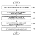
The operation of the EUV exposure apparatus according to this embodiment will be explained below with reference to FIG. 6. FIG. 6 is a flowchart showing the procedure of that operation. In step S61, the exhaust means 28 starts exhausting gas in the vacuum container 2 of the EUV exposure apparatus. After the degree of vacuum of the vacuum container 2 has reached a predetermined one suitable for exposure, the detector 31′ detects the content (partial pressure) of the residual gas component in the vacuum container 2 in step S62.
For example, it is possible to determine the relative quantity of the carbonaceous residual gas component to the water, on the basis of the contents of a gas component having a mass number of eighteen (water) and a gas component having a mass number of forty-five or more. In practice, the amount of a gas having a mass number of fifty-five often enables determination. As one example, it is possible to determine that the carbonaceous residual gas component exists in large quantities, when its content exceeds 1/10,000 that of the water (mass number: eighteen), and to determine that the carbonaceous residual gas component exists in small quantities when its content is equal to or less than 1/10,000 that of the water. However, this determination criterion depends on the type of existing gas, and may also be a numerical value different from 1/10,000 of the water content.
As described above, it is preferable to calculate in advance an appropriate quantity relationship between the water and the carbonaceous gas for each exposure condition by actually measuring the element distribution of the Ru film surface exposed with the EUV light in the vacuum container 2. The appropriate quantity relationship indicates one which provides the ability to suppress the oxidation of the Ru film and to suppress the deposition of carbon onto the Ru film. The above-described storage device stores the calculated quantitative relationship. The controller 35 uses the stored quantity relationship to determine the supply amount of at least one of water and a carbonaceous gas.
If the carbonaceous residual gas component exists in large quantities, the controller 35 opens the valve 32 of the water supply means comprising the water supply source 33, to supply water into the vacuum container 2. At this time, the controller 35 automatically controls the degree of opening of the valve 32, so as to obtain a proper partial pressure of the water, to retard the progress of oxidation of the Ru film. On the other hand, if the hydrocarbon-based residual gas component exists in small quantities, the controller 35 opens the valve 32′ of the carbonaceous gas supply means comprising the carbonaceous gas supply source 34, to supply a carbonaceous gas (for example, at least one of a hydrocarbon and an alcohol) into the vacuum container 2. At this time, the controller 35 automatically controls the degree of opening of the valve 32′, so as to obtain a proper partial pressure of the carbonaceous gas, to prevent carbon from excessively depositing on the Ru film.
When the supply amount or exhaust amount of the carbonaceous gas decreases or increases, so that the partial pressure of the carbonaceous gas decreases to the requested value, the partial pressure of the water sometimes decreases at the same time. Additionally, appropriate amounts of water and carbonaceous gas may optimally exert an effect of reducing oxidation and/or carbon deposition. In such cases, it is effective to introduce both water and a carbonaceous gas into the vacuum container 2, so as to appropriately control their partial pressures.
In this manner, in step S63, the controller 35 determines the supply amount of at least one of water (gas) and a carbonaceous gas, on the basis of the content (partial pressure) of the residual gas component in the vacuum container 2 detected using the detector 31′. The determination refers to the above-described information about an appropriate quantity relationship between the water and the carbonaceous gas for each exposure condition, which is calculated in advance and stored in the storage device 36.
Subsequently, in step S64, the controller controls the degree of opening of at least one of the valves 32 and 32′, on the basis of the determined supply amount of at least one of water and a carbonaceous gas. This provides the ability to supply at least one of water (gas) and a carbonaceous gas into the vacuum container 2. The controller regulates its supply amount by the degree of opening of at least one of the valves 32 and 32′.
The above-described method reduces the deposition of carbon onto the Ru film in the vacuum container 2, or reduces both the deposition of carbon onto the Ru film and the oxidation of the Ru film. The exposure apparatus exposes a wafer (substrate) 26 in the vacuum container 2 via reflecting means (mirror) 16 and 22 and reflecting mask 20, in step S65.
This embodiment has exemplified the case in which the exposure apparatus has both the water supply source 33 and carbonaceous gas supply source 34. However, it is conceivable that the content (partial pressure) of one of water (gas) and carbonaceous gas is always larger than that of the other one in the vacuum container 2, depending on the apparatus arrangement and/or apparatus use condition. In this case, the exposure apparatus may have a necessary one of the water supply source 33 and carbonaceous gas supply source 34.
A device manufacturing process using the above-described exposure apparatus will be explained next by taking a semiconductor device as an example. FIG. 6 is a flowchart showing the procedure for manufacturing a semiconductor device. In step 1 (circuit design), the circuit of a semiconductor device is designed. In step 2 (mask fabrication), a mask (also called an original or a reticle) is fabricated, on the basis of the designed circuit pattern.
In step 3 (wafer manufacture), a wafer (also called a substrate) is manufactured using a material such as silicon. In step 4 (wafer process), called a preprocess, the above-described exposure apparatus forms an actual circuit on the wafer by lithography using the mask and wafer. In step 5 (assembly), called a post-process, a semiconductor chip is formed from the wafer manufactured in step 4. This step includes processes, such as assembly (dicing and bonding) and packaging (chip encapsulation). In step 6 (inspection), inspections, including an operation check test and a durability test of the semiconductor device manufactured in step 5, are performed. A semiconductor device is completed with these processes and shipped, in step 7.
The wafer process in step 4 includes the following steps an oxidation step of oxidizing the wafer surface, a CVD step of forming an insulating film on the wafer surface, an electrode formation step of forming an electrode on the wafer by vapor deposition, an ion implantation step of implanting ions in the wafer, a resist processing step of applying a photosensitive agent to the wafer, an exposure step of causing the above-described exposure apparatus to expose the wafer having undergone the resist processing step, a development step of developing the wafer exposed in the exposure step, an etching step of etching portions other than the resist image developed in the development step, and a resist removal step of removing any unnecessary resist remaining after etching. By repeating these steps, a multilayered structure of circuit patterns is formed on the wafer.

Claims (18)

1. An exposure apparatus for exposing a substrate to exposure light via an original, said apparatus comprising:
a reflector which includes a multilayer film and a ruthenium film, and is configured to reflect the exposure light, said multilayer film reflecting the exposure light, and said ruthenium film being arranged on said multilayer film;
a vacuum container configured to contain said reflector;
an exhauster configured to exhaust gas in said vacuum container; and
a regulator configured to supply water vapor into said vacuum container and configured to regulate an amount of the water vapor in said vacuum container, based on an amount of carbonaceous gas in said vacuum chamber, so as to retard oxidation of said ruthenium film.
2. An apparatus according to claim 1, wherein said regulator is further configured to supply at least one of hydrocarbon and alcohol into said vacuum container, and to regulate an amount of the at least one of the hydrocarbon and the alcohol in said vacuum container.
3. An apparatus according to claim 2, wherein said regulator is configured to regulate a pressure of the at least one of the hydrocarbon and the alcohol in said vacuum container to a value not less than 1×10⁻¹⁰ Pa and not greater than 1×10⁻⁶ Pa.
4. An apparatus according to claim 1, further comprising an irradiator configured to irradiate said reflector with vacuum ultraviolet light.
5. An apparatus according to claim 1, wherein said regulator is configured to regulate a pressure of the water vapor in said vacuum container to a value not less than 1×10⁻⁶ Pa and not greater than 1×10⁻² Pa.
6. An apparatus according to claim 1, wherein the exposure light includes extreme ultraviolet light.
7. A method of manufacturing a device, said method comprising:
exposing a substrate to exposure light using an exposure apparatus as defined in claim 1;
developing the exposed substrate; and
processing the developed substrate to manufacture the device.
8. An exposure method of exposing a substrate to exposure light via an original, said method comprising:
exhausting gas in a vacuum container which contains a reflector that includes a multilayer film and a ruthenium film, and reflects the exposure light, the multilayer film reflecting the exposure light, and the ruthenium film being arranged on the multilayer film;
supplying water vapor into the vacuum container; and
regulating an amount of the water vapor in the vacuum container, based on an amount of carbonaceous gas in the vacuum container, so as to retard oxidation of the ruthenium film.
9. An exposure apparatus for exposing a substrate to exposure light via an original, said apparatus comprising:
a reflector including a multilayer film and a ruthenium film, and configured to reflect the exposure light, said multilayer film reflecting the exposure light, and said ruthenium film being arranged on said multilayer film;
a vacuum container configured to contain said reflector;
an exhauster configured to exhaust gas in said vacuum container;
a detector configured to detect an amount of water vapor and an amount of carbonaceous gas in said vacuum container;
a supplier being capable of supplying both water vapor and carbonaceous gas into said vacuum chamber and being capable of supplying only one of the water vapor and the carbonaceous gas into said vacuum container; and
a controller configured to control said supplier, based on the amount of the water vapor and the amount of carbonaceous gas detected by said detector, a ratio between an amount of the water vapor and an amount of the carbonaceous gas in said vacuum container being regulated to a predetermined ratio, so as to retard oxidation of said ruthenium film.
10. An apparatus according to claim 9, further comprising a storage configured to store information of the predetermined relationship.
11. An apparatus according to claim 10, wherein said storage is configured to store information of the predetermined relationship with respect to each of a plurality of exposure conditions.
12. An apparatus according to claim 11, wherein the exposure conditions include an irradiation condition of the exposure light.
13. An apparatus according to claim 11, wherein the exposure conditions include energy of the exposure light.
14. An apparatus according to claim 9, wherein the carbonaceous gas includes at least one of the hydrocarbon and alcohol.
15. An apparatus according to claim 9, further comprising an irradiator configured to irradiate said reflector with vacuum ultraviolet light.
16. An apparatus according to claim 9, wherein the exposure light is extreme ultraviolet light.
17. A method of manufacturing a device, said method comprising:
exposing a substrate to exposure light using an exposure apparatus as defined in claim 9;
developing the exposed substrate; and
processing the developed substrate to manufacture the device.
18. An exposure method of exposing a substrate to exposure light via an original, said method comprising:
an exhaust step of exhausting gas in a vacuum container, which contains a reflector that includes a multilayer film and a ruthenium film, and reflects the exposure light, the multilayer film reflecting the exposure light, and the ruthenium film being arranged on the multilayer film;
a detection step of detecting an amount of water vapor and an amount of carbonaceous gas in the vacuum container; and
a supply step of supplying at least one of water vapor and a carbonaceous gas in the vacuum container, by controlling a supplier configured to supply both water vapor and carbonaceous gas into the vacuum container and being capable of supplying only one of water vapor and carbonaceous gas into the vacuum container, based on the amount of the water vapor and the amount of the carbonaceous gas detected in said detection step, so that a ratio between the amount of water vapor and the amount of carbonaceous gas in the vacuum container is regulated to a predetermined ratio, so as to retard oxidation of the ruthenium film.
US11/614,416 2005-09-02 2006-12-21 Exposure apparatus and method, and device manufacturing method Expired - Fee Related US7724348B2 (en)

Applications Claiming Priority (3)

Application Number Priority Date Filing Date Title
JP2005255090A JP2007067344A (en) 2005-09-02 2005-09-02 Device and method for exposure, and method for manufacturing device
JP2005-255090 2005-09-02
PCT/JP2006/317208 WO2007026816A1 (en) 2005-09-02 2006-08-31 Exposure apparatus, method and process for producing device

Related Parent Applications (1)

Application Number Title Priority Date Filing Date
PCT/JP2006/317208 Continuation WO2007026816A1 (en) 2005-09-02 2006-08-31 Exposure apparatus, method and process for producing device

Publications (2)

Publication Number Publication Date
US20070097342A1 US20070097342A1 (en) 2007-05-03
US7724348B2 true US7724348B2 (en) 2010-05-25

Family

ID=37808899

Family Applications (1)

Application Number Title Priority Date Filing Date
US11/614,416 Expired - Fee Related US7724348B2 (en) 2005-09-02 2006-12-21 Exposure apparatus and method, and device manufacturing method

Country Status (5)

Country Link
US (1) US7724348B2 (en)
EP (1) EP1926128A4 (en)
JP (2) JP2007067344A (en)
KR (1) KR100907229B1 (en)
WO (1) WO2007026816A1 (en)

Families Citing this family (12)

* Cited by examiner, † Cited by third party
Publication number Priority date Publication date Assignee Title
JP2007067344A (en) 2005-09-02 2007-03-15 Canon Inc Device and method for exposure, and method for manufacturing device
JP2007234822A (en) 2006-02-28 2007-09-13 Canon Inc Exposure device, its control method, and device manufacturing method
JP2008263173A (en) * 2007-03-16 2008-10-30 Canon Inc Exposure apparatus
EP2026556B1 (en) 2007-07-31 2013-05-01 Samsung Electronics Co., Ltd. Multi-functional device having scanner module and image scanning apparatus employing the scanner module
US8358447B2 (en) 2007-07-31 2013-01-22 Samsung Electronics Co., Ltd. Scanner module and image scanning apparatus employing the same
US8379275B2 (en) * 2007-07-31 2013-02-19 Samsung Electronics Co., Ltd. Scanner module and image scanning apparatus employing the same
NL1036181A1 (en) 2007-11-30 2009-06-04 Asml Netherlands Bv A lithographic apparatus, a projection system and a device manufacturing method.
US9498846B2 (en) 2010-03-29 2016-11-22 The Aerospace Corporation Systems and methods for preventing or reducing contamination enhanced laser induced damage (C-LID) to optical components using gas phase additives
DE102011079450A1 (en) * 2011-07-20 2013-01-24 Carl Zeiss Smt Gmbh Optical arrangement with degradation suppression
US9323051B2 (en) 2013-03-13 2016-04-26 The Aerospace Corporation Systems and methods for inhibiting contamination enhanced laser induced damage (CELID) based on fluorinated self-assembled monolayers disposed on optics
CN108107681A (en) * 2016-11-25 2018-06-01 中国科学院长春光学精密机械与物理研究所 A kind of photoetching projection objective lens cavity precision monitoring device
US10274847B2 (en) 2017-09-19 2019-04-30 Taiwan Semiconductor Manufacturing Co., Ltd. Humidity control in EUV lithography

Citations (24)

* Cited by examiner, † Cited by third party
Publication number Priority date Publication date Assignee Title
US4618990A (en) 1984-11-15 1986-10-21 General Electric Company Edge enhancement filtering for digital fluorography images
US5012096A (en) 1989-05-20 1991-04-30 Fujitsu Limited Digital X-ray apparatus
US5220624A (en) 1990-04-10 1993-06-15 Dainippon Screen Mfg. Co., Ltd. Apparatus for reading images and method for enhancing the outlines of shapes
US5467404A (en) 1991-08-14 1995-11-14 Agfa-Gevaert Method and apparatus for contrast enhancement
US6009208A (en) 1995-08-21 1999-12-28 Lucent Technologies Inc. System and method for processing space-time images
US6072913A (en) 1996-12-13 2000-06-06 Fuji Photo Film Co., Ltd. Image processing method and apparatus
US20020053353A1 (en) 2000-03-13 2002-05-09 Shintaro Kawata Methods and apparatus for cleaning an object using an electron beam, and device-fabrication apparatus comprising same
JP2002237443A (en) 2001-02-09 2002-08-23 Nikon Corp Apparatus for eliminating contamination, method of eliminating contamination in optical aligner, and optical aligner
US20030016780A1 (en) 2001-07-18 2003-01-23 Matsushita Electric Industrial Co. Ltd. Soft X-ray reduction projection exposure system, soft X-ray reduction projection exposure method and pattern formation method
WO2003032329A1 (en) 2001-10-04 2003-04-17 Carl Zeiss Smt Ag Optical element and method for its manufacture as well as lightography apparatus and method for manufacturing a semiconductor device
US20030095240A1 (en) 2001-11-19 2003-05-22 Asm Lithography B.V. Lithographic projection apparatus, device manufacturing method, device manufactured thereby, cleaning unit and method of cleaning contaminated objects
US6721031B2 (en) 2001-06-15 2004-04-13 Canon Kabushiki Kaisha Exposure apparatus
US6721032B2 (en) 2001-07-30 2004-04-13 Canon Kabushiki Kaisha Exposure apparatus and control method therefor, and device manufacturing method
EP1413830A2 (en) 2002-10-24 2004-04-28 ROLLS-ROYCE plc Piloted airblast fuel injector with modified air splitter
JP2004207730A (en) 2002-12-20 2004-07-22 Asml Netherlands Bv Lithographic apparatus, method for manufacturing device, and device manufactured using the method
US6813335B2 (en) 2001-06-19 2004-11-02 Canon Kabushiki Kaisha Image processing apparatus, image processing system, image processing method, program, and storage medium
US6934003B2 (en) 2002-01-07 2005-08-23 Canon Kabushiki Kaisha Exposure apparatus and device manufacturing method
US6954255B2 (en) 2001-06-15 2005-10-11 Canon Kabushiki Kaisha Exposure apparatus
US20050236585A1 (en) * 2004-04-12 2005-10-27 Akira Miyake Exposure apparatus and exposure method using EUV light
JP2006049758A (en) 2004-08-09 2006-02-16 Nikon Corp Control method of exposure device, and method and device for exposure using the same
US7050648B1 (en) 1998-09-18 2006-05-23 Canon Kabushiki Kaisha Image processing apparatus, image processing method, and recording medium
JP2006319245A (en) 2005-05-16 2006-11-24 Canon Inc Exposure method, exposure device, and pattern forming method
US20070030466A1 (en) 2004-08-09 2007-02-08 Nikon Corporation Exposure apparatus control method, exposure method and apparatus using the control method, and device manufacturing method
US20070097342A1 (en) 2005-09-02 2007-05-03 Canon Kabushiki Kaisha Exposure apparatus and method, and device manufacturing method

Family Cites Families (8)

* Cited by examiner, † Cited by third party
Publication number Priority date Publication date Assignee Title
US6467404B1 (en) * 2000-08-28 2002-10-22 Temple Tag, Inc. Hot stamp machine for custom imprinting plastic identifier tags
JP2002248344A (en) * 2001-02-26 2002-09-03 Nikon Corp Extreme ultraviolet light generator as well as exposure device and method for manufacturing semiconductor using the same
EP1333323A3 (en) * 2002-02-01 2004-10-06 Nikon Corporation Self-cleaning reflective optical elements for use in x-ray optical systems, and optical systems and microlithography systems comprising same
DE10209493B4 (en) * 2002-03-07 2007-03-22 Carl Zeiss Smt Ag Method for avoiding contamination on optical elements, device for controlling contamination on optical elements and EUV lithography device
TWI254839B (en) * 2002-09-30 2006-05-11 Asml Netherlands Bv Lithographic apparatus and device manufacturing method
DE10321103A1 (en) * 2003-05-09 2004-12-02 Carl Zeiss Smt Ag Contamination avoidance method and EUV lithography apparatus
WO2005091076A2 (en) * 2004-03-05 2005-09-29 Carl Zeiss Smt Ag Methods for manufacturing reflective optical elements
JP4274366B2 (en) 2004-03-15 2009-06-03 クラリオン株式会社 In-vehicle device, control method for in-vehicle device, control program, and recording medium

Patent Citations (35)

* Cited by examiner, † Cited by third party
Publication number Priority date Publication date Assignee Title
US4618990A (en) 1984-11-15 1986-10-21 General Electric Company Edge enhancement filtering for digital fluorography images
US5012096A (en) 1989-05-20 1991-04-30 Fujitsu Limited Digital X-ray apparatus
US5220624A (en) 1990-04-10 1993-06-15 Dainippon Screen Mfg. Co., Ltd. Apparatus for reading images and method for enhancing the outlines of shapes
US5467404A (en) 1991-08-14 1995-11-14 Agfa-Gevaert Method and apparatus for contrast enhancement
US6009208A (en) 1995-08-21 1999-12-28 Lucent Technologies Inc. System and method for processing space-time images
US6072913A (en) 1996-12-13 2000-06-06 Fuji Photo Film Co., Ltd. Image processing method and apparatus
US7050648B1 (en) 1998-09-18 2006-05-23 Canon Kabushiki Kaisha Image processing apparatus, image processing method, and recording medium
US20020053353A1 (en) 2000-03-13 2002-05-09 Shintaro Kawata Methods and apparatus for cleaning an object using an electron beam, and device-fabrication apparatus comprising same
JP2002237443A (en) 2001-02-09 2002-08-23 Nikon Corp Apparatus for eliminating contamination, method of eliminating contamination in optical aligner, and optical aligner
US6721031B2 (en) 2001-06-15 2004-04-13 Canon Kabushiki Kaisha Exposure apparatus
US6954255B2 (en) 2001-06-15 2005-10-11 Canon Kabushiki Kaisha Exposure apparatus
US6813335B2 (en) 2001-06-19 2004-11-02 Canon Kabushiki Kaisha Image processing apparatus, image processing system, image processing method, program, and storage medium
US20030016780A1 (en) 2001-07-18 2003-01-23 Matsushita Electric Industrial Co. Ltd. Soft X-ray reduction projection exposure system, soft X-ray reduction projection exposure method and pattern formation method
JP3467485B2 (en) 2001-07-18 2003-11-17 松下電器産業株式会社 Soft X-ray reduction projection exposure apparatus, soft X-ray reduction projection exposure method, and pattern forming method
JP2003031483A (en) 2001-07-18 2003-01-31 Matsushita Electric Ind Co Ltd Soft x-ray reduction projection aligner, soft x-ray reduction projection exposure method, and pattern formation method
US6721390B2 (en) 2001-07-18 2004-04-13 Matsushita Electric Industrial Co., Ltd. Soft X-ray reduction projection exposure system, soft X-ray reduction projection exposure method and pattern formation method
US6721032B2 (en) 2001-07-30 2004-04-13 Canon Kabushiki Kaisha Exposure apparatus and control method therefor, and device manufacturing method
US7172788B2 (en) 2001-10-04 2007-02-06 Carl Zeiss Smt Ag Optical element and method for its manufacture as well as lithography apparatus and method for manufacturing a semiconductor device
US20040253426A1 (en) 2001-10-04 2004-12-16 Andrey Yakshin Optical element and method for its manufacture as well as lightography apparatus and method for manufacturing a semiconductor device
WO2003032329A1 (en) 2001-10-04 2003-04-17 Carl Zeiss Smt Ag Optical element and method for its manufacture as well as lightography apparatus and method for manufacturing a semiconductor device
US6724460B2 (en) 2001-11-19 2004-04-20 Asml Netherlands B.V. Lithographic projection apparatus, device manufacturing method, device manufactured thereby, cleaning unit and method of cleaning contaminated objects
JP2003188096A (en) 2001-11-19 2003-07-04 Asml Netherlands Bv Lithographic projection apparatus, device manufacturing method, device manufactured thereby, cleaning unit and method of cleaning contaminated object
US20030095240A1 (en) 2001-11-19 2003-05-22 Asm Lithography B.V. Lithographic projection apparatus, device manufacturing method, device manufactured thereby, cleaning unit and method of cleaning contaminated objects
US20060274292A1 (en) 2002-01-07 2006-12-07 Canon Kabushiki Kaisha Exposure apparatus and device manufacturing method
US6934003B2 (en) 2002-01-07 2005-08-23 Canon Kabushiki Kaisha Exposure apparatus and device manufacturing method
US7123343B2 (en) 2002-01-07 2006-10-17 Canon Kabushiki Kaisha Exposure apparatus and device manufacturing method
EP1413830A2 (en) 2002-10-24 2004-04-28 ROLLS-ROYCE plc Piloted airblast fuel injector with modified air splitter
US7095479B2 (en) 2002-12-20 2006-08-22 Asml Netherlands B.V. Lithographic apparatus, device manufacturing method and device manufactured thereby
US20050057734A1 (en) 2002-12-20 2005-03-17 Asml Netherlands B.V. Lithographic apparatus, device manufacturing method and device manufactured thereby
JP2004207730A (en) 2002-12-20 2004-07-22 Asml Netherlands Bv Lithographic apparatus, method for manufacturing device, and device manufactured using the method
US20050236585A1 (en) * 2004-04-12 2005-10-27 Akira Miyake Exposure apparatus and exposure method using EUV light
JP2006049758A (en) 2004-08-09 2006-02-16 Nikon Corp Control method of exposure device, and method and device for exposure using the same
US20070030466A1 (en) 2004-08-09 2007-02-08 Nikon Corporation Exposure apparatus control method, exposure method and apparatus using the control method, and device manufacturing method
JP2006319245A (en) 2005-05-16 2006-11-24 Canon Inc Exposure method, exposure device, and pattern forming method
US20070097342A1 (en) 2005-09-02 2007-05-03 Canon Kabushiki Kaisha Exposure apparatus and method, and device manufacturing method

Non-Patent Citations (7)

* Cited by examiner, † Cited by third party
Title
Anan, Mitsuhiro, et al. "Proceedings of the 45th Annual Meeting, "Japanese Journal of Radiological Technology, vol. 45, No. 8, Aug. 1989. p. 1030.
Bajt, Sa{hacek over (s)}a, et al. "Emerging Lithographic Technologies VII: Design and performance of capping layers for EUV multilayer mirrors," Proceedings of SPIE, vol. 5037, Part One, Feb. 25-27, 2003, Santa Clara, CA. pp. 236-248.
D. Dedrick, et al., "EUVL Thermophoretic Mask Protection", Second International EUVL Workshop, online, Oct. 19-20, 2000, International SEMATECH Manufacturing Iniative. http://www.sematech.org/resources/litho/meetings/euvI/20001019/index.htm, pp. 1-6.
Graham, Samuel, et al. "RF Oxygen Discharge Cleaning of Carbon from EUV Optics," Second International EUVL Workshop, online, Oct. 19-20, 2000, International SEMATECH Manufacturing Iniative. http://www.sematech.org/resources/litho/meetings/euvI/20001019/index.htm, pp. 1-6.
International Search Report dated Dec. 5, 2006, issued in corresponding International patent application No. PCT/JP2006/317208, forwarded in a Communication dated Dec. 12, 2006.
Klebanoff, L. 2nd International EUVL Workshop, online, Oct. 19-20, 2000. International SEMATECH Manufacturing Initiative, searched Jun. 10, 2005, pp. 1-9. http://www.sematech.org/meetings/archives/litho/euvl/20001019/205-ENV05-klebanoff.pdf.
M. Malinowski, et al., "Use of Molecular Oxygen to Reduce EUV-induced Carbon Contamination of Optics", Second International EUVL Workshop, online, Oct. 19-20, 2000, International SEMATECH Manufacturing Iniative. http://www.sematech.org/resources/litho/meetings/euvI/20001019/index.htm, pp. 1-7.

Also Published As

Publication number Publication date
KR20080019296A (en) 2008-03-03
EP1926128A4 (en) 2010-08-04
WO2007026816A1 (en) 2007-03-08
KR100907229B1 (en) 2009-07-10
JP2007067344A (en) 2007-03-15
JPWO2007026816A1 (en) 2009-03-12
US20070097342A1 (en) 2007-05-03
EP1926128A1 (en) 2008-05-28

Similar Documents

Publication Publication Date Title
US7724348B2 (en) Exposure apparatus and method, and device manufacturing method
CN100394547C (en) Optical projecting processor, manufacture and products, thereby, cleaning apparatus and method for pollutant therefrom
US7561247B2 (en) Method for the removal of deposition on an optical element, method for the protection of an optical element, device manufacturing method, apparatus including an optical element, and lithographic apparatus
US7518132B2 (en) Light source apparatus, exposure apparatus and device fabrication method
JP2005101537A (en) Lithography and method of manufacturing device using same
JP2009544148A (en) Lithographic apparatus getter and cleaning arrangement and method of cleaning a surface
JP2008263173A (en) Exposure apparatus
US7455880B2 (en) Optical element fabrication method, optical element, exposure apparatus, device fabrication method
US20070030466A1 (en) Exposure apparatus control method, exposure method and apparatus using the control method, and device manufacturing method
TW200428159A (en) Lithographic apparatus comprising a gas flushing system
JP2013534043A (en) Multilayer mirror [Cross-reference of related applications] [0001] This application is a review of US Provisional Application No. 61 / 348,999, filed May 27, 2010, which is incorporated herein by reference in its entirety. Insist on profit.
CN101371198B (en) Method for chemical reduction of an oxidized contamination material, or reducing oxidation of a contamination material and a conditioning system for doing the same
KR101625934B1 (en) Multilayer mirror and lithographic apparatus
Oestreich et al. Multilayer reflectance during exposure to EUV radiation
TWI422984B (en) Lithographic apparatus comprising a magnet, method for the protection of a magnet in a lithographic apparatus and device manufacturing method
US8004657B2 (en) Exposure apparatus, control method for the same, and device manufacturing method
TW202004844A (en) Lithographic apparatus
JP2003227898A (en) Multi-layer film reflecting mirror, soft x-ray optical equipment, exposure device and method for cleaning it
JP2005098930A (en) Multilayer-film reflector, method for reconditioning it and exposure system
US20090074962A1 (en) Method for the protection of an optical element of a lithographic apparatus and device manufacturing method
JP2010010380A (en) Optical system, aligner, and device manufacturing method
JP2010045355A (en) Radiation source, lithography apparatus and device manufacturing method
JP2002164267A (en) Aligner and method of manufacturing device
Huh et al. Lifetime of EUVL masks as a function of degree of carbon contamination and capping materials
JP2008182135A (en) Exposure equipment, optical instrument, exposure method, and manufacturing method of device

Legal Events

Date Code Title Description
AS Assignment

Owner name: CANON KABUSHIKI KAISHA,JAPAN

Free format text: ASSIGNMENT OF ASSIGNORS INTEREST;ASSIGNORS:GOMEI, YOSHIO;TAKASE, HIROMITSU;TERASHIMA, SHIGERU;SIGNING DATES FROM 20061214 TO 20061215;REEL/FRAME:018709/0128

Owner name: CANON KABUSHIKI KAISHA, JAPAN

Free format text: ASSIGNMENT OF ASSIGNORS INTEREST;ASSIGNORS:GOMEI, YOSHIO;TAKASE, HIROMITSU;TERASHIMA, SHIGERU;REEL/FRAME:018709/0128;SIGNING DATES FROM 20061214 TO 20061215

FEPP Fee payment procedure

Free format text: PAYOR NUMBER ASSIGNED (ORIGINAL EVENT CODE: ASPN); ENTITY STATUS OF PATENT OWNER: LARGE ENTITY

REMI Maintenance fee reminder mailed
LAPS Lapse for failure to pay maintenance fees
STCH Information on status: patent discontinuation

Free format text: PATENT EXPIRED DUE TO NONPAYMENT OF MAINTENANCE FEES UNDER 37 CFR 1.362

FP Lapsed due to failure to pay maintenance fee

Effective date: 20140525