US7724490B2 - Magnetic disk degaussing device and degaussing method - Google Patents
Magnetic disk degaussing device and degaussing method Download PDFInfo
- Publication number
- US7724490B2 US7724490B2 US11/789,575 US78957507A US7724490B2 US 7724490 B2 US7724490 B2 US 7724490B2 US 78957507 A US78957507 A US 78957507A US 7724490 B2 US7724490 B2 US 7724490B2
- Authority
- US
- United States
- Prior art keywords
- degaussing
- magnetic disk
- magnetic
- magnetic field
- disk
- Prior art date
- Legal status (The legal status is an assumption and is not a legal conclusion. Google has not performed a legal analysis and makes no representation as to the accuracy of the status listed.)
- Expired - Fee Related, expires
Links
Images


Classifications
-
- G—PHYSICS
- G11—INFORMATION STORAGE
- G11B—INFORMATION STORAGE BASED ON RELATIVE MOVEMENT BETWEEN RECORD CARRIER AND TRANSDUCER
- G11B5/00—Recording by magnetisation or demagnetisation of a record carrier; Reproducing by magnetic means; Record carriers therefor
- G11B5/02—Recording, reproducing, or erasing methods; Read, write or erase circuits therefor
- G11B5/024—Erasing
- G11B5/0245—Bulk erasing
Definitions
- the residual magnetism of magnetic disks of the in-plane magnetic recording system and the perpendicular magnetic recording system is removed by an AC degaussing method.
- the AC degaussing method is applied to degaussing, for example, a magnetic disk of the in-plane magnetic recording system
- a magnetic field is applied in an in-plane direction parallel to the axis of easy magnetization of the recording layer of the magnetic disk with a permanent magnet or an electromagnet to invert the direction of the magnetic field so that the magnetism may be gradually reduced.
- the residual magnetism of a magnetic disk of the perpendicular magnetic recording system is removed by applying magnetic fields of opposite polarities in a direction perpendicular to the surface of the magnetic disk, i.e., a direction parallel to the axis of easy magnetization of the recording layer of the magnetic disk, to invert the magnetism of the recording layer repeatedly so that the magnetism of the recording layer may gradually approach zero.
- a data erasing method disclosed in Japanese Patent Publication No. 201-331904 (“Patent document 1”) combines magnets such that magnetic poles of opposite polarities are adjacent to each other and erases data recorded on the magnetic disk by leakage flux from the interface between the magnetic poles of opposite polarities.
- a data erasing device disclosed in Japanese Patent Publication No. 2005-276319 (“Patent document 2”) applicable to magnetic disks respectively of both the in-plane and the perpendicular magnetic recording system uses a magnetic field varying from perpendicular direction at the inner circumference of the disk to a parallel direction at the outer circumference of the disk.
- a magnetic field applying method disclosed in Japanese Patent Publication No. 2004-326960 (“Patent document 3”) places magnets opposite to the upper and the lower surface of a magnetic disk, respectively, and slides the magnets along the recording surface of the magnetic disk.
- a magnetic field of a magnetic intensity not lower than the coercive force of the magnetic disk is needed to degauss the magnetic disk.
- the recent magnetic recording systems including the perpendicular magnetic recording systems records data in a high recording density on magnetic disks and hence the coercive force of magnetic disks has been increased. Accordingly, a magnetic field of a high magnetic intensity needs to be applied to the magnetic disk for high-density recording.
- Embodiments in accordance with the present invention provide a degaussing device and a degaussing method capable of efficiently degaussing a magnetic disk, especially, a magnetic disk of the perpendicular magnetic recording system, without resorting to a magnetic field of a high intensity.
- Particular embodiments provide a degaussing method for degaussing a magnetic disk not yet installed in a magnetic disk drive by applying an external magnetic field to the magnetic disk by a degaussing device.
- An embodiment of the method includes disposing the magnetic disk in the degaussing device such that the direction of an external magnetic field is inclined at an angle to the axis of easy magnetization of the magnetic disk.
- FIG. 1 is a perspective view of a degaussing device 100 in a first embodiment according to the present invention.
- FIG. 2 is a block diagram of a control system for controlling the degaussing device 100 in the first embodiment.
- FIG. 3 is a perspective view of a magnetic disk holding unit 101 included in the degaussing device 100 in the first embodiment.
- FIG. 4 is a perspective view of a magnetic disk holding unit included in a degaussing device in a second embodiment according to the present invention.
- FIG. 5 is a sectional view of the degaussing device in the first embodiment taken from the Y-direction.
- FIG. 6 is a flow chart of a degaussing method to be carried out by the degaussing device in the first embodiment.
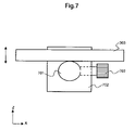
- FIG. 7 is a view of a tilting mechanism for the degaussing device shown in FIG. 3 or 5 .
- FIG. 8 is a view of another tilting mechanism for the degaussing device shown in FIG. 3 or 5 .
- FIG. 9 is a view of a turning mechanism for the degaussing device shown in FIG. 4 .
- FIG. 10 is a view of a third tilting mechanism for the degaussing device shown in FIG. 3 or 5 .
- FIG. 11 is a sectional view of a magnetic disk of the perpendicular magnetic recording system.
- FIG. 12 is a sectional view of a magnetic disk of the in-plane magnetic recording system.
- FIG. 13 is a graph showing the relation between the intensity H o of a magnetic field to be applied to the magnetic disk by the degaussing device and the angle between the axis of easy magnetization of the magnetic disk and the direction of the applied magnetic field.
- FIG. 14 is a typical view of a magnetic disk drive 1401 provided with a magnetic disk 301 .
- Embodiments in accordance with the present invention relate to a degaussing device for and a degaussing method of removing residual magnetism from a magnetic disk. It is an object of embodiments in accordance with the present invention to degauss a magnetic disk efficiently. More particularly, it is an object of embodiments in accordance with the present invention to provide a degaussing device and a degaussing method capable of efficiently degaussing a magnetic disk of the perpendicular recording system without resorting to a magnetic field of a high magnetic intensity.
- a method for degaussing a magnetic disk before being incorporated into a magnetic disk drive by applying an external magnetic field to the magnetic disk by a degaussing device includes, disposing the magnetic disk in the degaussing device such that the direction of an external magnetic field is inclined at an angle to the axis of easy magnetization of the magnetic disk.
- Embodiments of the present invention provide a degaussing device for degaussing a magnetic disk including a magnetic field applying means for applying an external magnetic field to the magnetic disk, a support means for supporting the magnetic disk, and a tilting means for tilting the support means relative to the direction of the external magnetic field.
- Embodiments of the present invention are capable of efficiently degaussing a magnetic disk without resorting to a magnetic field of a high magnetic intensity.
- FIG. 1 is a perspective view of a degaussing device 100 in accordance with a first embodiment of the present invention.
- the degaussing device 100 is provided in its central part with a magnetic disk holding unit 101 covered with a door 102 .
- the door 102 is opened, magnetic disks, not shown, are put in the magnetic disk holding unit 101 , the door 102 is closed, and then the degaussing device 100 is operated.
- the magnetic disk holding unit 102 is formed in a size sufficient for holding twenty-five magnetic disks.
- FIG. 2 is a block diagram of a control system for controlling the degaussing device 100 in the first embodiment.
- a main controller 208 detects a current supplied to an input control thyristor 201 by an ac power source.
- a step-up transformer 202 raises the voltage of the current and a rectifier 203 rectifies the current to charge a capacitor 204 .
- the main controller 208 measures the voltage of the charged capacitor 204 .
- the main controller 208 drives a trigger 206 to turn on the main thyristor 205 upon the increase of the voltage of the capacitor 204 to a predetermined voltage.
- the main thyristor 205 is turned on the electricity accumulated in the capacitor 204 is discharged and a current is supplied to an oil 207 .
- FIG. 3 is a perspective view of the magnetic disk holding unit 101 of the degaussing device 100 according to the first embodiment.
- the magnetic disk holding unit 101 has a capacity sufficient for entirely covering the magnetic disks. Thus the entire surfaces of the magnetic disks can be simultaneously degaussed.
- a coil 304 is wound such that a disk caddy 302 made of a nonconductive material and capable of holding a plurality of magnetic disks 301 can be contained in the magnetic disk holding unit 101 .
- a current 301 flows through the coil 304 in a direction opposite the Y-direction parallel to the Y-axis shown in FIG. 3 . Consequently, a magnetic field 306 is applied in the X-direction parallel to the X-axis shown in FIG. 3 to the magnetic disk holding unit 101 .
- the disk caddy 302 is mounted on a table 303 disposed in the magnetic disk holding unit 101 .
- FIG. 11 is a sectional view of a magnetic disk of the perpendicular magnetic recording system and FIG. 12 is the in-plane magnetic recording system.
- the magnetic disk of the perpendicular magnetic recording system has a soft magnetic layer 1102 , a hard magnetic recording layer 1103 and a nonmagnetic protective layer 1104 superposed in that order on a nonconductive substrate 1101 .
- the axis of easy magnetization of the recording layer 1103 is perpendicular to the surface of the magnetic disk.
- the magnetic disk of the in-plane recording system has a hard magnetic recording layer 1202 and a nonmagnetic protective layer 1203 superposed in that order on a nonmagnetic substrate 1201 .
- the axis of easy magnetization of the recording layer 1202 is parallel to the surface of the magnetic disk.
- the degaussing device 100 is used for degaussing magnetic disks of the perpendicular magnetic recording system.
- Magnetic disks 301 are loaded on the disk caddy 302 .
- the disk caddy 302 can carry one or a plurality of magnetic disks 301 .
- the disk caddy 302 can hold the magnetic disks 301 with their surfaces extended perpendicularly to the surface of the table 303 .
- the magnetic disks 301 are those before being incorporated into magnetic disk drives.
- An external magnetic field can be applied to the magnetic disk 301 without being obstructed by the casing of a magnetic disk drive and hence the magnetic disk can be more efficiently degaussed.
- the magnetic disk drive can be efficiently assembled by the following magnetic disk drive assembling process.
- FIG. 5 is a sectional view of the degaussing device 100 in the first embodiment taken from the Y-direction. As shown in FIG. 5 , the table 303 of the magnetic disk holding unit 101 is tilted to tilt the magnetic disks 301 loaded on the disk caddy, not shown in FIG. 5 , at a predetermined angle to the magnetic field 306 applied to the magnetic disks 301 by the degaussing device 100 .
- the angle between the axis of easy magnetization of the magnetic disks 301 and the direction of the applied magnetic field 306 is 0° in the conventional degaussing device
- the angle between the axis of easy magnetization of the magnetic disks 301 and the direction of the applied magnetic field 306 is ⁇ in the degaussing device 100 in the first embodiment.
- FIG. 6 is a flow chart of a degaussing method to be carried out by the degaussing device 100 in the first embodiment.
- the degaussing method will be described with reference to FIGS. 1 , 3 and 5 .
- Magnetic disks 301 are loaded on the disk caddy 302 .
- the disk caddy 302 loaded with the magnetic disks 301 is mounted on the table 303 of the magnetic disk holding unit 101 in step S 601 .
- the table 303 is tilted relative to the X-axis shown in FIG. 3 or 5 by a tilting mechanism, not shown, in step S 602 to tilt the magnetic disks 302 relative to the X-axis.
- a main switch is turned on to connect the degaussing device 100 to the power source in step S 603 and a current is supplied to the coil 304 in step S 604 . Consequently, the coil 304 creates the magnetic field 306 .
- a time for which a current is supplied to the coil 304 for degaussing is, for example, 10 ms.
- the application of the magnetic field 306 is terminated in step S 605 , and then the main switch is turned off to disconnect the degaussing device 100 from the power source in step 606 . Then, the disk caddy 302 holding the magnetic disks 301 is taken out from the degaussing device 100 in step S 607 .
- FIG. 13 is a graph showing the relation between the intensity of the magnetic field to be applied to the magnetic disk 301 by the degaussing device 100 and the angle between the axis of easy magnetization of the magnetic disk 301 and the direction of the applied magnetic field.
- the magnetic disk 301 can be degaussed by a magnetic field having an intensity of 6 kOe or below when the angle between the axis of easy magnetization and the direction of the applied magnetic field is between 5° and 80°.
- the intensity of the magnetic field necessary for degaussing when the angle is 40° is about two-thirds of that of the magnetic field necessary for degaussing when the angle is 0°.
- the axis of easy magnetization of the recording layer of a magnetic disk of the in-plane magnetic recording system is parallel to the surface of the magnetic disk
- the axis of easy magnetization of the recording layer of a magnetic disk of the perpendicular magnetic recording system is perpendicular to the surface of the magnetic disk.
- the coercive force of a magnetic disk is defined by the intensity of a magnetic field to be applied to the magnetic disk in a direction parallel to the axis of easy magnetization to reduce the magnetism to zero. Therefore, a magnetic field having an intensity sufficiently higher than the coercive force of the magnetic disk needs to be, applied to the magnetic disk for degaussing.
- FIG. 13 shows that there is a tendency for the effective coercive force of the magnetic disk to decrease relative to a magnetic field inclined to the axis of easy magnetization of the recording layer.
- the magnetic disks can be degaussed by a magnetic field having a comparatively low intensity when the table 303 shown in FIG. 5 is tilted such that the angle between the direction of the magnetic field applied to the magnetic disks by the degaussing device and the axis of easy magnetization of each of the magnetic disks is between 5° and 80°.
- the table 303 is tilted such that the angle between the direction of the magnetic field applied to the magnetic disks by the degaussing device and the axis of easy magnetization of each of the magnetic disks is 45° to achieve degaussing the magnetic disks by a magnetic field of a low intensity.
- FIG. 7 A tilting mechanism for the degaussing device shown in FIG. 3 or 5 is shown in FIG. 7 by way of example.
- the table 303 is supported on an arm 701 held by an arm holder 702 .
- the arm 701 is cylindrical and is capable of turning about its axis.
- the table 303 supported on the arm 701 is tilted along the z-axis shown in FIG. 7 when the arm 701 turns.
- the arm 701 is fixed with a fixing screws 703 to hold the table 303 at a predetermined inclination.
- FIG. 8 Another tilting mechanism for the degaussing device shown in FIG. 3 or 5 is shown in FIG. 8 by way of example.
- the table 303 is supported on an arm 801 by supporting the table 303 on a support 805 and fixing the table 303 to the support 805 .
- the arm 801 is connected to an arm 802 capable of turning about an axis parallel to the X-axis shown in FIG. 8 to turn the table 303 about an axis parallel to the X-axis.
- the table 303 is turned on the support 805 about an axis parallel to the Y-axis.
- the arms 801 and 802 are fixed with fixing screws 803 and 804 to hold the table 303 at a predetermined inclination. Since the table 303 can be turned about the two axes, the angle between the direction of the applied magnetic field and the axis of easy magnetization of the magnetic disk can be easily adjusted.
- FIG. 10 A third tilting mechanism for the degaussing device shown in FIG. 3 or 5 is shown in FIG. 10 .
- Each of the tilting mechanisms shown in FIGS. 7 and 8 uses the fixing screws to hold the table 303 at a predetermined inclination.
- the tilting mechanism shown in FIG. 10 is controlled by a controller 1001 to adjust the inclination of the table 1002 automatically to a predetermined inclination.
- the controller 1001 includes a position adjusting unit 1002 .
- the controller 1001 controls the inclination of the table 303 automatically according to a numerical value indicating an angle given to the position adjusting unit.
- FIG. 4 is a perspective view of a magnetic disk holding unit 101 included in a degaussing device in a second embodiment according to the present invention.
- the basic construction of the degaussing device in the second embodiment is the same as that of the degaussing device in the first embodiment.
- the degaussing device in the second embodiment is applied to degaussing a magnetic disk of the in-plane magnetic recording system show in FIG. 12 .
- the axis of easy magnetization of the magnetic disk of the in-plane magnetic recording system is parallel to the surface of the magnetic disk.
- the magnetic disks 301 are mounted on the table 303 such that the direction of a magnetic field 306 to be applied to the magnetic disks 301 by the degaussing device will be parallel to the axes of easy magnetization of the magnetic disks, the table 303 is tilted by the tilting method by which the degaussing device in the first embodiment tilted the table 303 , and then, the magnetic disks are degaussed.
- the directional relation between the axis of easy magnetization of each magnetic disk 301 and the magnetic field 306 to be applied to the magnetic disks 301 by the degaussing device can be adjusted simply by properly changing the direction in which the magnetic disks 301 contained in the disk caddy 302 are mounted on the table 303 by a manual operation.
- the table 303 can be turned in the directions ⁇ for fine adjustment.
- the degaussing device can degauss magnetic disks of either of the perpendicular magnetic recording system or the in-plane magnetic recording system.
- FIG. 9 shows a turning mechanism for the degaussing device shown in FIG. 4 by way of example.
- the table 303 is supported on an arm 901 having one end connected to a ball 902 .
- the ball 902 is held by a bearing 903 on a ball holder 904 .
- the ball 902 can turn in the bearing 903 about the Y-axis to turn the table 302 in the directions ⁇ .
- the ball 902 can turn in all directions, so that the table 303 can be tilted in an optional direction.
- FIG. 14 is a typical view of a magnetic disk drive 1401 provided with a magnetic disk 301 .
- the magnetic disk drive 1401 includes a spindle motor 1402 for rotatively driving the magnetic disk 301 , and a suspension 1403 having an end part on which a magnetic head 1404 for reading information from and writing information to the magnetic disk 301 .
- the degaussing device disposed outside the magnetic disk drive 1401 applies a magnetic field 306 to the magnetic disk 301 being rotated by the spindle motor 1402 for ac degaussing.
Abstract
Description
Claims (18)
Applications Claiming Priority (2)
| Application Number | Priority Date | Filing Date | Title |
|---|---|---|---|
| JP2006-118792 | 2006-04-24 | ||
| JP2006118792A JP2007293964A (en) | 2006-04-24 | 2006-04-24 | Degaussing device and degaussing method for magnetic disk |
Publications (2)
| Publication Number | Publication Date |
|---|---|
| US20070247776A1 US20070247776A1 (en) | 2007-10-25 |
| US7724490B2 true US7724490B2 (en) | 2010-05-25 |
Family
ID=38619260
Family Applications (1)
| Application Number | Title | Priority Date | Filing Date |
|---|---|---|---|
| US11/789,575 Expired - Fee Related US7724490B2 (en) | 2006-04-24 | 2007-04-24 | Magnetic disk degaussing device and degaussing method |
Country Status (3)
| Country | Link |
|---|---|
| US (1) | US7724490B2 (en) |
| JP (1) | JP2007293964A (en) |
| CN (1) | CN101064107A (en) |
Cited By (2)
| Publication number | Priority date | Publication date | Assignee | Title |
|---|---|---|---|---|
| US20110149427A1 (en) * | 2009-12-17 | 2011-06-23 | Nelson Cheng | Suppressing adjacent track interference/far track interference (ati/fti) in a hard disk drive (hdd) by an external magnetic field |
| US11961648B2 (en) | 2019-10-21 | 2024-04-16 | Beijing University Of Technology | Rapid demagnetization method based on characteristics of magnetic media |
Families Citing this family (10)
| Publication number | Priority date | Publication date | Assignee | Title |
|---|---|---|---|---|
| JP2007026535A (en) * | 2005-07-15 | 2007-02-01 | Hitachi Global Storage Technologies Netherlands Bv | Data erasing device and method |
| JP4116066B1 (en) * | 2007-06-21 | 2008-07-09 | 七山 美智賜 | Magnetic data erasing device |
| JP5202236B2 (en) | 2007-11-13 | 2013-06-05 | 株式会社半導体エネルギー研究所 | Micro electromechanical switch and method for manufacturing the same |
| JP4799571B2 (en) * | 2008-01-28 | 2011-10-26 | 七山 美智賜 | Magnetic data eraser |
| JP5570035B2 (en) * | 2011-11-04 | 2014-08-13 | アドバンス・デザイン株式会社 | Magnetic data erasing device |
| TWI547943B (en) * | 2011-11-15 | 2016-09-01 | 愛德萬斯設計股份有限公司 | Magnetic data eraser |
| JP5875166B1 (en) * | 2014-12-04 | 2016-03-02 | 三央工業株式会社 | Combined destruction device |
| US20170243682A1 (en) * | 2016-02-24 | 2017-08-24 | Advanced Design Corp. | Magnetic date eraser |
| US10242699B1 (en) * | 2018-05-23 | 2019-03-26 | Phiston Technologies, Inc. | Single pulse degaussing device with rotary actuated chamber access doors |
| US10657345B1 (en) * | 2019-07-02 | 2020-05-19 | Phiston Technologies, Inc. | Media destruction verification apparatus |
Citations (9)
| Publication number | Priority date | Publication date | Assignee | Title |
|---|---|---|---|---|
| JPH01173401A (en) | 1987-12-28 | 1989-07-10 | Sumitomo Metal Mining Co Ltd | Erasing device for high coercive force vertical magnetic recording medium |
| JPH05266534A (en) | 1992-03-19 | 1993-10-15 | Hitachi Electron Eng Co Ltd | Method for canceling leaked magnetic field of magneto-optical disk evaluation device |
| US5574616A (en) * | 1992-04-17 | 1996-11-12 | Garner Industries, Inc. | Degaussing technique |
| US20020163747A1 (en) * | 2001-02-23 | 2002-11-07 | Fuji Photo Film Co., Ltd. | Method and apparatus of magnetically transferring information signal from master medium to slave medium |
| US6594099B2 (en) | 2000-05-16 | 2003-07-15 | International Business Machines Corporation | Apparatus for erasing data stored on a magnetic disk |
| JP2004326960A (en) | 2003-04-25 | 2004-11-18 | Hoya Corp | Demagnetizing method and manufacturing method for perpendicular magnetic recording disk and demagnetizing device for perpendicular magnetic recording disk |
| JP2005276319A (en) | 2004-03-24 | 2005-10-06 | Lease Up System:Kk | Method and device for erasing magnetic information recorded on magnetic recording medium |
| US7050256B1 (en) * | 2004-06-29 | 2006-05-23 | The United States Of America As Represented By The Administrator Of The National Aeronautics And Space Administration | Fast erase method and apparatus for digital media |
| US20080013244A1 (en) * | 2006-07-14 | 2008-01-17 | Schultz Robert A | Method and Apparatus for Permanent Magnet Erasure of Magnetic Storage Media |
-
2006
- 2006-04-24 JP JP2006118792A patent/JP2007293964A/en active Pending
-
2007
- 2007-04-24 US US11/789,575 patent/US7724490B2/en not_active Expired - Fee Related
- 2007-04-24 CN CNA2007101012063A patent/CN101064107A/en active Pending
Patent Citations (9)
| Publication number | Priority date | Publication date | Assignee | Title |
|---|---|---|---|---|
| JPH01173401A (en) | 1987-12-28 | 1989-07-10 | Sumitomo Metal Mining Co Ltd | Erasing device for high coercive force vertical magnetic recording medium |
| JPH05266534A (en) | 1992-03-19 | 1993-10-15 | Hitachi Electron Eng Co Ltd | Method for canceling leaked magnetic field of magneto-optical disk evaluation device |
| US5574616A (en) * | 1992-04-17 | 1996-11-12 | Garner Industries, Inc. | Degaussing technique |
| US6594099B2 (en) | 2000-05-16 | 2003-07-15 | International Business Machines Corporation | Apparatus for erasing data stored on a magnetic disk |
| US20020163747A1 (en) * | 2001-02-23 | 2002-11-07 | Fuji Photo Film Co., Ltd. | Method and apparatus of magnetically transferring information signal from master medium to slave medium |
| JP2004326960A (en) | 2003-04-25 | 2004-11-18 | Hoya Corp | Demagnetizing method and manufacturing method for perpendicular magnetic recording disk and demagnetizing device for perpendicular magnetic recording disk |
| JP2005276319A (en) | 2004-03-24 | 2005-10-06 | Lease Up System:Kk | Method and device for erasing magnetic information recorded on magnetic recording medium |
| US7050256B1 (en) * | 2004-06-29 | 2006-05-23 | The United States Of America As Represented By The Administrator Of The National Aeronautics And Space Administration | Fast erase method and apparatus for digital media |
| US20080013244A1 (en) * | 2006-07-14 | 2008-01-17 | Schultz Robert A | Method and Apparatus for Permanent Magnet Erasure of Magnetic Storage Media |
Cited By (3)
| Publication number | Priority date | Publication date | Assignee | Title |
|---|---|---|---|---|
| US20110149427A1 (en) * | 2009-12-17 | 2011-06-23 | Nelson Cheng | Suppressing adjacent track interference/far track interference (ati/fti) in a hard disk drive (hdd) by an external magnetic field |
| US8169730B2 (en) * | 2009-12-17 | 2012-05-01 | Hitachi Global Storage Technologies, Netherlands, B.V. | Suppressing adjacent track interference/far track interference (ATI/FTI) in a hard disk drive (HDD) by an external magnetic field |
| US11961648B2 (en) | 2019-10-21 | 2024-04-16 | Beijing University Of Technology | Rapid demagnetization method based on characteristics of magnetic media |
Also Published As
| Publication number | Publication date |
|---|---|
| CN101064107A (en) | 2007-10-31 |
| US20070247776A1 (en) | 2007-10-25 |
| JP2007293964A (en) | 2007-11-08 |
Similar Documents
| Publication | Publication Date | Title |
|---|---|---|
| US7724490B2 (en) | Magnetic disk degaussing device and degaussing method | |
| US5315464A (en) | Disk apparatus and manufacturing method thereof | |
| US9076463B2 (en) | Magnetic recording head and disk device with the same | |
| CN100449612C (en) | Trailing edge taper design and method for making a perpendicular write head with shielding | |
| US9311934B1 (en) | Symmetrical STO for oscillation with both polarity bias | |
| US20060114590A1 (en) | Thermally assisted magnetic recording method | |
| US6532136B2 (en) | Hard disk drive apparatus | |
| US7092188B2 (en) | Method for assembly level disk erase | |
| JP2656733B2 (en) | Magnetic reinitialization method and apparatus for thin film magnetoresistive read head | |
| EP0618578B1 (en) | Active electromagnetic latch for the head actuator of a hard disk drive | |
| US7626800B2 (en) | Bulk erase tool for erasing perpendicularly recorded media | |
| EP0725966B1 (en) | Magnetic parking device for disk drive | |
| US7548406B2 (en) | Method for utilizing a bulk erase tool to erase perpendicularly recorded media | |
| JP2755104B2 (en) | Disk unit | |
| JP2003068038A (en) | Magnetic disk device | |
| JP2009187632A (en) | Information recording/reproducing device | |
| US7050255B2 (en) | System and apparatus for assembly level disk erase | |
| US7423844B2 (en) | Recording disk drive | |
| JP3175395B2 (en) | Magnetic head, magnetic head load / unload method, and magneto-optical recording / reproducing apparatus | |
| JP3864489B2 (en) | Disk unit | |
| JP4241666B2 (en) | Head actuator and disk device using the same | |
| JP2000011407A (en) | Object lens driving device and optical disk device | |
| JPH0341645A (en) | Optical disk device | |
| JPH0652504A (en) | Magneto-optical disk driving device | |
| JP2001273608A (en) | Thin-film magnetic head, its manufacturing method, head assembly composed of the head, and magnetic disk device loading the head |
Legal Events
| Date | Code | Title | Description |
|---|---|---|---|
| AS | Assignment |
Owner name: HITACHI GLOBAL STORAGE TECHNOLOGIES NETHERLANDS B. Free format text: ASSIGNMENT OF ASSIGNORS INTEREST;ASSIGNORS:TUMURA, HITOSHI;MORI, HIROKI;KITAMURA, MITSURU;AND OTHERS;REEL/FRAME:019456/0848 Effective date: 20070412 |
|
| CC | Certificate of correction | ||
| AS | Assignment |
Owner name: HGST, NETHERLANDS B.V., NETHERLANDS Free format text: CHANGE OF NAME;ASSIGNOR:HGST, NETHERLANDS B.V.;REEL/FRAME:029341/0777 Effective date: 20120723 Owner name: HGST NETHERLANDS B.V., NETHERLANDS Free format text: CHANGE OF NAME;ASSIGNOR:HITACHI GLOBAL STORAGE TECHNOLOGIES NETHERLANDS B.V.;REEL/FRAME:029341/0777 Effective date: 20120723 |
|
| FPAY | Fee payment |
Year of fee payment: 4 |
|
| AS | Assignment |
Owner name: WESTERN DIGITAL TECHNOLOGIES, INC., CALIFORNIA Free format text: ASSIGNMENT OF ASSIGNORS INTEREST;ASSIGNOR:HGST NETHERLANDS B.V.;REEL/FRAME:040821/0550 Effective date: 20160831 |
|
| FEPP | Fee payment procedure |
Free format text: MAINTENANCE FEE REMINDER MAILED (ORIGINAL EVENT CODE: REM.) |
|
| LAPS | Lapse for failure to pay maintenance fees |
Free format text: PATENT EXPIRED FOR FAILURE TO PAY MAINTENANCE FEES (ORIGINAL EVENT CODE: EXP.) |
|
| STCH | Information on status: patent discontinuation |
Free format text: PATENT EXPIRED DUE TO NONPAYMENT OF MAINTENANCE FEES UNDER 37 CFR 1.362 |
|
| FP | Lapsed due to failure to pay maintenance fee |
Effective date: 20180525 |