US7724782B2 - Interval centroid based watermark - Google Patents
Interval centroid based watermark Download PDFInfo
- Publication number
- US7724782B2 US7724782B2 US12/051,882 US5188208A US7724782B2 US 7724782 B2 US7724782 B2 US 7724782B2 US 5188208 A US5188208 A US 5188208A US 7724782 B2 US7724782 B2 US 7724782B2
- Authority
- US
- United States
- Prior art keywords
- intervals
- interval
- watermark
- flow
- group
- Prior art date
- Legal status (The legal status is an assumption and is not a legal conclusion. Google has not performed a legal analysis and makes no representation as to the accuracy of the status listed.)
- Active, expires
Links
Images


Classifications
-
- H—ELECTRICITY
- H04—ELECTRIC COMMUNICATION TECHNIQUE
- H04L—TRANSMISSION OF DIGITAL INFORMATION, e.g. TELEGRAPHIC COMMUNICATION
- H04L63/00—Network architectures or network communication protocols for network security
- H04L63/04—Network architectures or network communication protocols for network security for providing a confidential data exchange among entities communicating through data packet networks
- H04L63/0428—Network architectures or network communication protocols for network security for providing a confidential data exchange among entities communicating through data packet networks wherein the data content is protected, e.g. by encrypting or encapsulating the payload
-
- H—ELECTRICITY
- H04—ELECTRIC COMMUNICATION TECHNIQUE
- H04L—TRANSMISSION OF DIGITAL INFORMATION, e.g. TELEGRAPHIC COMMUNICATION
- H04L2463/00—Additional details relating to network architectures or network communication protocols for network security covered by H04L63/00
- H04L2463/103—Additional details relating to network architectures or network communication protocols for network security covered by H04L63/00 applying security measure for protecting copy right
Definitions
- sender anonymity means that the identity of the information sender is hidden
- receiver anonymity means that the identity of the information receiver is hidden.
- Unlinkability of sender and receiver refers to the property that the sender and receiver of a communication cannot be identified even if the sender and receiver are known to be of communicating with someone. Since anonymity is the state of lacking identity, anonymous communication can only be achieved by removing all the identifying characteristics from the anonymized network flows.
- FIG. 1A is a diagram showing an intra-flow transformation where Chaff is added to an original packet flow.
- FIG. 1B is a diagram showing an intra-flow transformation where packets are dropped (de-chaff) from an original packet flow.
- FIG. 1C is a diagram showing a repacketization intra-flow transformation where packets in an original packet flow are merged.
- FIG. 1D is a diagram showing a repacketization intra-flow transformation where packets in an original packet flow are fragmented.
- FIG. 2A is a diagram showing inter-flow transformations where multiple packet flows are combined into a single packet flow.
- FIG. 2B is a diagram showing inter-flow transformations where a single packet flow is broken up into multiple packet flows.
- FIG. 2C is a diagram showing inter-flow transformations where a fragmented packet flow is combined into a single packet flow.
- FIG. 3 is a plot showing empirical distributions of the remainders of modulo 1000 operations over normally distributed random variables.
- FIG. 4 is a plot showing empirical distributions of the remainders of modulo 1000 operations over exponentially distributed random variables.
- FIG. 5 is a diagram showing the random grouping of time intervals of a packet flow as per an aspect of an embodiment of the present invention.
- FIG. 6 is a diagram illustrating the random assignment of time intervals for embedding different watermark bits as per an aspect of an embodiment of the present invention.
- FIG. 7 is a diagram illustrating the effect of the packet delay strategy over the distribution of packets within an interval of size T as per an aspect of an embodiment of the present invention.
- FIG. 8 is a diagram illustrating the effect of watermark encoding over a distribution of Y i as per an aspect of an embodiment of the present invention.
- FIG. 9 is a diagram illustrating the offline decoding of a flow that was watermarked with a 32-bit watermark under different offsets as per an aspect of an embodiment of the present invention.
- FIG. 10 is a diagram illustrating a setup used to conduct real-time experiments using an aspect of an embodiment of the present invention.
- FIG. 11 is a table that shows statistics of Web traffic collected during real-time experiments using an aspect of an embodiment of the present invention.
- FIG. 12 is a plot showing watermark detection true positive rates during real-time experiments using an aspect of an embodiment of the present invention.
- FIG. 13 is a plot showing false positive rates between watermarked flows and different watermarks during real-time experiments using an aspect of an embodiment of the present invention.
- FIG. 14 is a plot showing watermark detection rates of split subflows during real-time experiments using an aspect of an embodiment of the present invention.
- FIG. 15 is a plot showing watermark detection rates under different timing perturbations during real-time experiments using an aspect of an embodiment of the present invention.
- FIG. 16 is a block diagram of a system to watermark a packet flow with an interval centroid based watermark as per an aspect of an embodiment of the present invention.
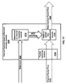
- FIG. 17 is a block diagram of an interval centroid based watermark encoder module as per an aspect of an embodiment of the present invention.
- FIG. 18 is a block diagram showing aspects of an original packet flow as per an aspect of an embodiment of the present invention.
- FIG. 19 is a block diagram of a watermarked packet flow as per an aspect of an embodiment of the present invention.
- FIG. 20 is a block diagram of an interval centroid based watermark decoder module as per an aspect of an embodiment of the present invention.
- FIG. 21 is a flow diagram of interval centroid based watermark encoding as per an aspect of an embodiment of the present invention.
- FIG. 22 is a flow diagram of interval centroid based watermark decoding as per an aspect of an embodiment of the present invention.
- FIG. 23 is a block diagram of a unidirectional verification system using embodiments of the present invention.
- FIG. 24 is a block diagram of a bidirectional verification system using embodiments of the present invention.
- FIG. 25 is a block diagram of a unidirectional verification system using embodiments of the present invention.
- FIG. 26 is a block diagram of a bidirectional verification system using embodiments of the present invention.
- Embodiments of the present invention are interval centroid-based watermark encoder and decoders that exploit the fundamental limitation of low-latency anonymous communication systems that low-latency anonymizing systems do not eliminate the packet timing correlation between the anonymized flow and the original flow. Therefore, there exists mutual information in the packet timing domain between the anonymized flow and the original flow. Such mutual information forms the very foundation for the unique identification and tracking the anonymized flow.
- a technique used in embodiments of the present invention is to transparently watermark the packet flow by slightly adjusting the timing of selected packets. If the embedded unique watermark survives various flow transformations, the watermarked network flow can be uniquely identified and thus linked to it original sender and receiver.
- This network flow watermarking technique may be used to attack low-latency anonymous communication systems without global monitoring capability. To break the unlinkability of sender and receiver, one only needs to monitor and perturb the network flows to and from potential senders and receivers to verify the packet flow. For example, a malicious Web site could watermark the Web traffic returned to its visitors, and determine if some suspected user has visited its Web site by checking if that user has received the (potentially anonymized) watermarked traffic. With appropriate monitoring capability, the presently disclosed embodiments for flow watermarking may also be used to attack the sender and receiver anonymity.
- embodiments were able to “penetrate” the Total Net Shield, the “ultimate solution in online identity protection” of www.anonymizer.com. It took less than 11 minutes of active surfing traffic from www.usatoday.com to achieve virtually 100% true positive rate and less than 0.3% false positive rate at the same time in linking the sender and receiver of the Web traffic that was anonymized by the Total Net Shield of www.anonymizer.com.
- the analytical and empirical results demonstrate that 1) the anonymity provided by low-latency anonymous communication systems is fundamentally limited, 2) there exists practical attack to break the anonymity provided by existing low-latency anonymous communication systems, and 3) existing low latency anonymous communication systems need to be revisited.
- the network flow identification problem is formulated in the context of network information flow, and elaborate on the relationship between the network flow identification and anonymous communication by reviewing the flow transformations used in existing anonymous communication systems.
- a network generally has multiple network flows between different nodes. Some network flows are essentially correlated with each other in that they are part of the transmission of the same information. For example, multicast flows from the same source are essentially correlated if they convey the same information. All of the connections in a connection chain across stepping stones are essentially correlated since those connections have the same essential payload even if the payload is encrypted.
- network information flow is used to represent the transmission path of some information along the network. Therefore, any communication between different nodes in a network, whether it has single or multiple sources/destinations, is a network information flow.
- a network information flow may consist of multiple network flows which may appear very different due to various flow transformations. As indicated by the multicast example, a network information flow is not necessarily linear.
- a generic problem of network information flow is how to determine those network flows that belong to any particular network information flows. This problem is defined as the networkflow identification problem.
- Network flow identification is inherently related to anonymous communication whose goal is to conceal the true identities and relationships among the communicating parties. For example, if one can identify and authenticate those network flows that belong to any particular network information flow, then it may be possible to link a network flow to its information source and destination. Thus, one can link the information sender and receiver.
- anonymous communication systems usually mix multiple network information flows among multiple communicating parties and transform each network flow substantially. If the transformed network flows do not have any identifying characteristics that can be linked to their information sources or destinations, anonymity will be achieved.
- Intra-flow transformations are those transformations that are within the boundary of the flow without involving any other flow during the transformation.
- Inter-flow transformations are those that involve more than one flow.
- FIG. 1A , FIG. 1B , FIG. 1C and FIG. 1D illustrate most common forms of intra-flow transformation: adding chaff ( FIG. 1A ), packet dropping ( FIG. 1B ), and repacketization ( FIG. 1C and FIG. 1D ).
- chaff refers to any bogus packet added to the flow that was not part of the original flow.
- any cover traffic used in anonymous communication systems [12, 15] is chaff.
- Packet dropping can happen naturally, but it may be introduced deliberately as an effort to achieve anonymity [19].
- Repacketization can either combine two or more closely adjacent packets into a larger packet ( FIG. 1C ) or split a packet into multiple smaller packets ( FIG. 1D ). Both forms of repacketization can occur naturally and be triggered deliberately.
- SSH is known to combine closely adjacent packets into larger packets.
- IP fragmentation happens when the packet size is larger than the Maximum Transmission Unit (MTU) along the transmission path. Without considering the packet size, one can view two forms of repacketization as either chaff ( FIG. 1A ) or de-chaff ( FIG. 1B ).
- FIG. 2A , FIG. 2B and FIG. 2C illustrates most common forms of inter-flow transformation: flow mixing ( FIG. 2A ), flow splitting ( FIG. 2B ) and flow merging ( FIG. 2C ).
- Flow mixing refers to mixing some flow f 0 with some unrelated flows: f 1 , . . . , f n to generate mixed flow f′ 0 .
- a flow f 0 could be split into multiple subflows: f 0 1 , . . . , f 0 n , which could be later merged.
- flow mixing combines a flow with unrelated flows
- flow merging combines a flow with flows that belong to the same network information flow.
- flow mixing and flow merging appear the same.
- the flows f 1 , . . . , f n mixed with flow f 0 in FIG. 2A (flow mixing) and flows f 0 2 , . . . , f 0 n merged with flow f′ 0 in FIG. 2C (flow merge) can be thought as chaff added to flow f 0 and f′ 0 , respectively.
- flow splitting can be thought as a form of packet dropping (or de-chaffing) from the subflow's point of view.
- n p >0 packets P 1 , . . . , P np in the 2n intervals.
- packet P i would occur within interval ⁇ t′ i /T ⁇ .
- ⁇ t i t′ i mod T (1)
- dividing a duration T d of a packet flow into equal size intervals is essentially a modulo operation, and the packets' relative positions within their respective intervals are essentially the remainders of the modulo operations on those packets in duration T d .
- other embodiments may divide the intervals into unequal sizes. This may be useful in situations when the packet flow has intervals with few packets.
- FIG. 3 and FIG. 4 show the empirical distributions of the remainders of modulo 1000 operations over normally and exponentially distributed random variables, respectively. They clearly show that the remainder of modulo operation over random variables of different distributions is approximately uniformly distributed.
- any randomly chosen offset o>0 and any interval size T>0 the relative positions of all packets within their respective intervals ( ⁇ t i ) are uniformly distributed.
- Cent ⁇ ( I i ) 1 n 1 ⁇ ⁇ j - 0 n i - 1 ⁇ ⁇ ⁇ ⁇ t i j ( 4 )
- interval I i may be defined as Cent(I i ) to be T/2. Other definitions may also be used in differing embodiments.
- the following process may be used to independently and randomly choose n intervals out of the 2n intervals: (1) sequentially scan each of the 2n intervals and (2) independently and randomly choose the current interval with probability 0.5. One may expect to have n intervals randomly chosen.
- FIG. 5 shows the random grouping of the time intervals of a packet flow.
- FIG. 6 illustrates the random assignment of the time intervals for embedding different watermark bits.
- N i,j A and N i,j B to represent the total packet numbers in interval I i,j A and I i,j B , respectively.
- N i A and N i B represent the total packet number of group A and B intervals, respectively, assigned for encoding watermark bit i.
- each interval was assigned randomly, with equal probability, to group A and B, and each group A and B intervals were randomly assigned, with equal probability, for encoding each watermark bit, each of the 2n intervals has equal probability to be assigned for each watermark bit.
- each interval has
- ⁇ t i,j,k A and ⁇ t i,j,k B represent the k-th packet in interval I i,j A and I i,j B , respectively.
- watermark bit i may be encoded and decoded into the difference between A i and B i .
- Let Y i A i ⁇ B i (9)
- a i maybe deliberately increased so that Y i will be more likely to be positive than negative.
- B i may be deliberately increased so that Y i will be more likely to be negative than positive.
- ⁇ ⁇ ⁇ t i , j , k ′ a + ( T - a ) ⁇ ⁇ ⁇ ⁇ t i , j , k T ( 10 )
- FIG. 7 illustrates the effect of the packet delay strategy over the distribution of packets within an interval of size T.
- this embodiment of watermark encoding actually shifts the distribution of Y i to the left or right for a/2, and it makes the resulting distributions of Y i 1 and Y i 0 slightly more clustered than that of Y i .
- FIG. 8 illustrates the effect of the watermark encoding over distribution of Y i .
- the probability that encoded bit ‘0’ is mistakenly decoded as bit ‘1’ is Pr[Y i 0 >0]
- the probability that encoded bit ‘1’ is mistakenly decoded as bit ‘0’ is Pr [Y i 1 ⁇ 0].
- the upper bound of the decoding error probability may be derived by applying Chebyshev inequality to Y i 0 and Y i 1 .
- Pr ⁇ [ Y i 1 ⁇ 0 ] 1 2 ⁇ Pr ⁇ [ ⁇ Y i 1 - E ⁇ ( Y i 1 ) ⁇ ⁇ a 2 ] ⁇ T 2 + ( T - a ) 2 6 ⁇ a 2 ⁇ N i ( 14 )
- a pseudo random number generator (RNG) and a seed s is used to randomly group and assign each interval to a different watermarking bit.
- the random interval grouping and assignment are determined and represented by the RNG and seed s used.
- Tuple ⁇ o, T, RNG, s> represents the complete information needed for the watermarking encoder and decoder to determine the pseudo-random interval grouping and assignment for encoding and decoding the watermark, and it will be shared only between the watermarking encoder and decoder.
- the decoder should be able to derive the exact random interval grouping and assignment used for encoding the watermark.
- the correct decoding offset not only depends on the value of o but also the clock setting of the decoding host as well as any timing perturbation on the packet timing.
- offset o will point to the correct decoding start time.
- the clocks of the watermark encoding and decoding hosts are not perfectly synchronized, o may point to the wrong decoding start time.
- any network delay, network delay jitter, deliberate timing perturbation could shift the correct decoding offset.
- the interval centroid-based watermarking could self-synchronize the decoding offset with the encoding offset even if 1) the clocks of the watermark encoding host and decoding host are not synchronized; 2) there is substantial network delay, delay jitter or timing perturbation on the watermarked flows. Due to the symmetric nature of the random interval grouping and assignment for watermark encoding and decoding, the decoding with wrong offsets appears random and it tends to have l/2 different bits than the encoded l-bit watermark. This property gives an easy way to determine if the decoding offset used is correct.
- FIG. 9 shows the offline decoding of a flow that was watermarked with a 32-bit watermark (with 10 second offset) under different offsets, and it clearly shows that only the offset that is very close to the correct one yields the best watermark decoding.
- any other packets added to or mixed with the original flow as chaff or chaff packets may be considered.
- Pc, 1 , . . . , P c,m added to packet flow P 1 , . . . , P n
- the resulting flow P′ 1 , . . . , P′ m+n P′ i is either P j or P c,j ) is a mix of the original flow and the chaff.
- Chaff packets as originating from another random packet flow will now be considered.
- the relative offsets of all chaff packets within their respective intervals are uniformly distributed. Therefore, the chaff added to a watermarked flow tends to shift the centroid within each interval toward the center of the interval, which would weaken the strength of the embedded watermark.
- the negative impact of chaff is quantitatively analyzed.
- the offsets of the k-th chaff packet added to the j-th group A interval I i,j A and group B interval I i,j B are represented by ⁇ circumflex over (t) ⁇ i,j,k A and ⁇ circumflex over (t) ⁇ i,j,k B respectively.
- M i,j A and M i,j B be the number of chaff packets added to interval I i,j A and I i,j B , respectively.
- R A M i A N i A
- R B M i B N i B
- Packet dropping, merging adjacent packets, and splitting flows into multiple subflows may decrease the number of packets in the original flow. This effect can be summarize as de-chaff. Since flow duration is randomly divided into multiple intervals and those intervals are randomly grouped for each watermark bit, any packet lost should be uniformly distributed within each interval I i,j A and I i,j B . Therefore, when there are enough packets left in the flow, the centroids of all the intervals tend to remain the same even after the packets have been randomly dropped and merged. This property would allow the embedded watermark to persist even after random packet dropping, merging, or flow splitting.
- FIG. 16 is a block diagram of a system as per an aspect of an embodiment of the present invention.
- an original packet flow 1610 is received by an interval centroid based watermark encoder module 1630 .
- the interval centroid based watermark encoder module 1630 applies a watermark 1620 to the original packet flow 1610 yielding a watermarked packet flow 1640 .
- This packet flow may travel through one or more networks 1650 to a destination.
- the destination may use an interval centroid based watermark decoder module 1660 to retrieve the watermark 1620 .
- FIG. 17 is an expanded block diagram of an embodiment of the interval centroid based watermark encoder module 1630 shown in FIG. 16 .
- the interval centroid based watermark encoder module 1630 may include a packet receiving module 1730 , a watermark to interval mapping module 1710 , and a relative packet time adjustment module 1740 .
- the packet receiving module 1610 may be configured to receive the original packet flow 1610 .
- the original packet flow 1610 may be a part of a larger packet flow. This original packet flow 1610 should have a temporal duration 1860 and a starting point 1850 .
- FIG. 18 is a block diagram of an original packet flow 1610 .
- the packet flow containing a temporally separated sequence of packets ( 1831 , 1832 , 1839 ) separated by existing inter-packet delays ( 1841 , 1842 and 1849 ).
- At least part of the packet flow 610 may be separated into a temporally separated sequence of intervals ( 1821 , 1822 and 1829 ).
- the interval times were equal.
- the temporally separated sequence of intervals ( 1821 , 1822 and 1829 ) may begin after an offset 1852 from the starting point 1850 .
- the offset could be any measurable length of time less that is less than the duration minus the sum of the interval times. In some embodiments, the offset could be zero. At least one of the temporally separated sequence of intervals ( 1821 , 1822 and 1829 ) may be a group A interval ( 2022 , shown in FIG. 20 ). At least one other of the temporally separated sequence of intervals ( 1821 , 1822 and 1829 ) may be a group B interval ( 2024 , shown in FIG. 20 ).
- the watermark to interval mapping module 1710 may be configured to map watermark bits to unique pair(s) of intervals.
- the unique pair(s) of intervals should include a unique group A interval 2021 and a unique group B interval 2024 .
- Each of the watermark bits may represent a bit value.
- the relative packet time adjustment module 1740 may be configured to embed watermark bit(s) into mapped intervals by modifying the relative time between the temporally separated sequence of packets in an interval and the beginning of the same interval. So, for the illustrative example, the relative packet time adjustment module 1740 may increase the relative time 1981 between the temporally separated sequence of packets ( 1831 , 1832 , 1839 ) in unique group A interval 1821 that is mapped to each of the watermark bit(s) that represents a first bit value and the beginning of the same each unique group A interval 1821 .
- the relative packet time adjustment module 1740 may increase the relative time between the temporally separated sequence of packets in unique group B interval 1822 and the beginning of the same unique group B interval 1822 .
- the first and second values may represent binary values such as ‘0’ and ‘1’. However, one skilled in the art will recognize that other values may also be represented. For example, the relative packet times may be increased by different values to help embed a trinary or higher value.
- FIG. 19 is block diagram of a resultant group A watermarked interval 1821 representing a first bit value in watermarked packet flow 1640 .
- This watermarked interval 1821 is similar to the original packet flow 1610 with the addition of the interval watermark adjustment delays ( 1951 , 1952 an 1959 ).
- Each of these interval watermark adjustment delays ( 1951 , 1952 an 1959 ) are introduced to increase the relative packet times 1981 , 1982 , and 1989 ).
- the group B interval that is paired with this group A interval 1821 would not have extended adjustment delays.
- the group B interval watermark adjustment delays would be extended instead of the group A interval watermark adjustment delays ( 1951 , 1952 an 1959 ).
- interval centroid based watermark encoder module 1630 embeds data using timing delays, it does not care about the content of the data. Therefore, this encoder could be used with encrypted, compressed or in-the-clear packets.
- FIG. 20 is a block diagram of an interval centroid based watermark decoder 1660 as per an aspect of an embodiment of the present invention. As shown, the interval centroid based watermark decoder 1660 includes a watermarked packet receiving module 2010 , a centroid determination module 2040 and a watermark bit determination module 2080 .
- the watermarked packet receiving module 2010 may be configured to receive watermarked packet flow 1640 .
- the watermarked packet flow 1640 may have a duration 1860 and a starting point 1850 and contain a temporally separated sequence of packets ( 1831 , 1832 and 1839 ).
- At least part of the watermarked packet flow 1821 may be divided into a temporally separated sequence of intervals ( 1821 , 1822 and 1829 ) that begin after an offset 1852 from the starting point 1850 .
- At least one of the temporally separated sequence of intervals ( 1821 , 1822 and 1829 ) may be a group A interval (e.g. 1821 ) and at least one other of the temporally separated sequence of intervals may be a group B interval (e.g. 1822 ).
- Each of at least one bit of a watermark may be mapped to at least one unique pair of intervals, where each of the unique pair of intervals includes a unique group A interval and a unique group B interval.
- the relative packet time measurement module 2030 may be configured to measure: group A relative packet times and group B relative packet times.
- the group A relative packet times (see e.g. 1981 , 1982 and 1989 ) my be the relative time between the temporally separated sequence of packets in each unique group A interval and the beginning of each unique group A interval.
- group B relative packet times may be the relative time between the temporally separated sequence of packets in each unique group B interval and the beginning of each unique group B interval.
- the centroid determination module 2040 may be configured to calculate a group A centroid 2052 using group A relative packet times 2032 and a group B centroid 2064 using the group B relative packet times 2034 .
- the group A centroid calculation may be performed by a group A centroid module 2050 .
- the group B centroid calculation may be performed by a group B centroid module 2060 .
- a centroid difference 2072 may be calculated by centroid to difference module 2070 using the group A centroid 2052 and the group B centroid 2064 .
- Watermark bit determination module 2080 may be configured to analyze the centroid difference(s) 2072 to determine watermark bit value(s). For example, the watermark bit determination module 2080 may be configured to determine that a watermark bit mapped to unique pair(s) of intervals represents a first bit value if the centroid difference 2072 for the unique pair(s) of intervals is greater than a first threshold. Similarly, the watermark bit determination module 2080 may be configured to determine that the watermark bit mapped to unique pair(s) of intervals represents a second bit value if the centroid difference 2072 for unique pair(s) of intervals is less than a second threshold.
- the watermark bit determination module 2080 may be configured to evaluate the centroid difference 2072 using one or more other criterions to determine a bit value represented by watermark bit(s) mapped to pair(s) of intervals.
- the bit value need not be constrained to two values in all embodiments.
- Some embodiments of the present invention may be a computer-readable media tangibly embodying a program of instructions executable by a computer to perform a method for applying an interval centroid based watermark to a packet flow intended to travel through a physical network.
- FIG. 21 shows a flow diagram of a possible embodiment of such a method.
- the method may operate on a packet flow that contains a temporally separated sequence of packets.
- the packet flow will preferably have a duration T f and a starting point.
- the watermark may have l watermark bits and a redundancy r, where each of the l watermark bits are representative of a value.
- the watermark bit values may be one of two or more values.
- a quantity of 2n intervals may be defined where n is the product of length l and redundancy value r.
- the intervals divide a duration Td that is less than or equal to duration Tf.
- the 2n intervals may begin after an offset from the starting point.
- n intervals may be selected as group A intervals. This selection process may be non-deterministic (such as a random selection) or deterministic. Examples of non-deterministic selection mechanisms may include random or pseudo random selection. Examples of deterministic selection mechanisms may include using a look-up table or defined algorithm to make selections.
- n intervals that are distinct from the group A intervals maybe selected as group B intervals.
- n interval pairs may be generated by grouping n unique group A intervals with n unique group B intervals.
- a quantity of the r interval pairs may be assigned to each of the l watermark bits. Making r greater than one increases the redundancy of the watermark and thus should increase the probability of the watermark being recovered properly by a later decoding stage.
- Watermark bit(s) with a first watermark bit value may encoded into the packet stream by increasing the relative packet time between each of the temporally separated sequence of packets in the group A intervals of the n interval pairs assigned to each of the l watermark bits that are to represent the first bit value and the beginning of the same group A intervals at 2161 .
- watermark bit(s) with a second watermark bit value may encoded into the packet stream by increasing the relative packet time between each of the temporally separated sequence of packets in the group B intervals of the n interval pairs assigned to each of the l watermark bits that are to represent the second bit value and the beginning of the same group B intervals.
- FIG. 21 shows a flow diagram of a method that may be embodied on a computer-readable media tangibly as a program of instructions executable by a computer to perform a method for decoding the interval centroid based watermark from the watermarked packet flow encoded using a method like that disclosed in FIG. 21 and earlier.
- relative packet times may be measured for the temporally separated sequence of packets in the n group A and n group B intervals.
- a group A centroid for each of the quantity of n group A intervals may be calculated using the relative packet times measured in each of the quantity of n group A intervals at 2220 .
- a group B centroid may be calculated for each of the quantity of n group B intervals using the relative packet times measured in each of the quantity of n group B intervals at 2230 .
- a centroid difference may be calculated for the interval pairs of group A intervals and group B intervals at 2240 using the group A centroid and the group B centroid.
- Watermark bit values represented by the n interval pairs may be determined at 2250 . It may be determined that an interval pair represents a first watermark bit value if the centroid difference calculated for that interval pair is greater than a first threshold. Similarly, it may be determined that an interval pair represents a second watermark bit value if the centroid difference calculated for that interval pair is less than a second threshold.
- a value for the maybe determined watermark using the watermark bit values represented by the n interval pairs.
- Embodiments of the present invention may be used in systems that desire a covert channel to pass information. Embodiments of such systems are shown in FIG. 23 , FIG. 24 , FIG. 25 and FIG. 26 . These illustrative systems use the previously disclosed embodiments to provide a covert channel that may be used to hide data such as server/customer authentication information in an IP packet stream without modifying any of the IP packets. In these systems, the hidden data may be hidden in the packet stream as a watermark. Examples of applications that can use systems like these include: secure verification of communication partners; secret peer-to-peer communications; tracking network devices; and tracing communications.
- Each of these applications may be implemented using two common components: a hidden data inserter/encoder module and a hidden data extractor/decoder module.
- the hidden data inserter/encoder module may be implemented using a watermark encoder and the hidden data extractor may be implemented using a watermark decoder.
- FIG. 23 and FIG. 24 show two implementations of a server verification mechanism.
- FIG. 23 shows a unidirectional system configured to allow a customer 2330 receive authentication information in a secure manner from a vendor 2310 such as a bank using a generic client side computer 2360 running a web browser 2380 .
- a server application 2344 such as remote banking software and web browser 2380 may communicate in their usual way with the server application 2344 passing outgoing data packets 2345 to the web browser 2380 and the web browser 2380 passing return data packets 2382 back to the server application 2344 .
- the server 2340 can add unique customer information 2343 (possibly obtained using a customer database 2342 ) to the data stream 2345 using a hidden channel marker/encoder module 2350 .
- This hidden channel marker/encoder module 2350 may be internal or external to the server 2340 .
- This combined stream 2351 may now consist of a covert communication channel 2352 and an overt communication channel 2354 .
- the covert communication channel 2352 may carry the server/customer authentication data and an overt communication channel 2354 may carry the normal IP data packets from the server application 2344 .
- This combined communications channel 2351 may be transported to a customers computer 2360 through a network 2320 such as the Internet where a hidden data extractor/decoder and verifier module 2370 may extract the unique customer information, verifies it and passes the verification data 2372 to the customers' web browser effectively informing the customer that they are in fact communicating with the vendor server 2340 and not a site pretending to be the vendor server 2340 .
- the hidden data extractor/decoder and verifier module 2370 may also pass other hidden data besides just verification data to the web browser 2380 .
- FIG. 24 is similar to FIG. 23 with the addition on a return channel 2491 with a secure component 2494 making it a bidirectional system configured to allow a customer 2330 and server 2340 to authenticate each other using a bidirectional hidden channels 2352 and 2494 .
- the customer computer 2360 may now run a customer application 2380 that returns a combined communications stream 2491 to the server 2340 that includes hidden data 2382 with its normal return data packets 2382 .
- the hidden data 2382 may be encoded into the covert communications channel 2494 that resides in the timing of the overt communications channel 2492 by covert channel marker/encoder module 2490 .
- the server 2340 may now use a hidden data extractor/decoder and verifier module 2446 to extract the hidden data 2382 .
- This hidden data may be verified by hidden data extractor/decoder and verifier module 2446 .
- the verification 2448 and/or hidden data 2382 may be passed to the server application 2344 .
- the remote server 2340 ran a banking software application 2344 that using the covert channel marker/encoder module 2350 and covert channel marker/encoder module 2490 (in FIG. 24 ) to add an invisible layer of security and/or authentication.
- this mechanism may be used with many other applications than just banking. For example, this mechanism may be used to pass secure messages between interested parties, or used to pass secrets such as encryption keys that may be used in combination with other security mechanism.
- FIG. 25 shows a unidirectional backchannel between a server 2510 and a user 2550 .
- a web support application 2512 in combination with an optional database provide a back channel marker encoder module 2530 with a normal IP packet stream 2516 and backchannel data 2518 to a backchannel marker/encoder module 2530 .
- Backchannel marker/encoder module 2530 may encode the backchannel data 2518 into the timing of IP packet stream 2516 to produce combined stream 2522 .
- This mechanism is effectively watermarking the IP packet stream 2516 with the backchannel data 2518 .
- This combined (watermarked) stream 2522 may be communicated over a network 2540 to a user 2550 .
- the network may be an open network such as the Internet or a closed network such as a corporate intra-net.
- the user may use a back channel extractor/decoder module 2552 to retrieve the backchannel data 2518 .
- the back channel extractor/decoder module 2552 may be embodied in software or hardware.
- Software embodiments may be implemented as a stand alone program, as a applet or as a browser plug-in for a web browser 2554 .
- the user 2550 may then provide a normal return data stream 2556 to the server 2510 . This system should enable data to be hidden data such that it is undetectable by analysis of packet data alone.
- FIG. 26 shows an extended version of the system in FIG. 25 .
- the first difference to notice is that the back channel marker/encoder module 2530 is embedded in a router 2630 along with a back channel data extractor/decoder module 2690 . This was illustrated this way to show that one of the multiple sites in which modules such as the back channel marker/encoder module 2530 or back channel data extractor/decoder module 2690 could be located. Locating these modules in a communication path may allow the modules to mark and extract hidden data from a larger number of communications that may originate from a larger number of sources.
- a second variation is the substitution of a client application 2670 for the more generic web browser application 2554 . Again, this is to demonstrate the many ways that the system can system can operate.
- the client application may generate a return IP data stream 2677 and backchannel data 2678 .
- the backchannel marker/encoder module 2680 may encode the backchannel data 2678 into the timing of IP packet stream 2677 to produce combined stream 2682 .
- Data stream 2682 may be communicated through a network 2640 to a device such as back channel data extractor/decoder 2690 .
- Back channel data extractor/decoder 2690 may then extract the backchannel data 2678 from the IP data stream 2677 .
- the backchannel data 2678 and/or the IP data stream 2677 may then be provided to the server or other destination.
- this technology not be limited to a server and user.
- the system could mark and extract data from any point in a communications chain. It could be used between peers or merely inserted at a convenient tap location such as in a network card, a router, etc.
- FIG. 10 illustrates the setup of the real-time experiments.
- Live Web traffic from www.usatoday.com was watermarked and to see if a watermark applied by a test embodiment could penetrate the Total Net Shield service provided by www.anonymizer.com.
- An Apache server 1050 was set up as a reverse proxy to www.usatoday.com 1060 so that all the Web pages of www.usatoday.com could be accessed by pointing a browser 1010 to the URLs of the Apache server 1050 .
- This setup also enabled most Web traffic from www.usatoday.com to be watermarked at the Apache server machine 1050 .
- the Apache reverse proxy 1050 did not catch all of the Web traffic between the Web servers of www.usatoday.com 1060 and the client 1010 .
- the Web traffic from www.usatoday.com reached the entry point(s) of anonymizer.com 1030 , it consisted of watermarked traffic 1042 mixed with unwatermarked traffic 1046 (shown collectively as 1040 ).
- both the average packet numbers and average packet rates at the client side were about 90% of those at the server side.
- the average packet sizes at the client side were only about 43% of the average packet sizes at the server side.
- the average information flow rates (in terms of bytes/second) at the client side were around 39% of those at the server side.
- 10 transformed flows were further generated by adding uniformly distributed chaff (or bogus packets) of rates between 10 to 100 packets/second. An attempt was then made to decode the 1000 transformed watermarked flows with correct watermarking parameters. For all rates of chaff, a 100% watermark detection rate was obtained while getting no more than a 0.5% watermark detection false positive rate. Since the average packet rate of the original unwatermark synthetic flow is only 0.8 packet/second, the watermarked flow had only about 512 packets.
- a chaff rate of 100 packets/second is over 120 times more than the packet rate of the original flow. Also tried was watermark decoding with normally distributed chaff, and virtually a 100% watermark detection rate was achieved when the normally distributed chaff was 4 times more than the original packets.
- FIG. 14 shows the average watermark detection rates from various subflows under different Hamming distance thresholds. The figure indicates that splitting a flow into a few subflows does not make a flow unidentifiable as long as each subflow has a reasonable number of packets. In specific, 80% watermark detection rate was obtained with Hamming Distance threshold 5 on each of the 3 subflows that were split from a 512-packet flow. These results imply that a watermarked flow can be uniquely identified even if substantial portion of its packets have been dropped.
- FIG. 15 shows the average watermark detection rates under various levels of random timing perturbation. It clearly indicates that the interval centroid based watermarking scheme is robust against any timing perturbation that is less than the interval size T.
- a number of low-latency anonymous communication systems [1, 24, 9, 25, 12, 15, 22, 4, 17] have been developed based on proxies or MIXes.
- Onion Routing [24], and its second generation, Tor [9] use public key encryption on a pre-determined sequence of proxies to protect the transport of TCP flows.
- Crowds [25] uses randomly selected proxies to hide the information's sender and receiver. However, none of these methods were designed to provide the unlinkability of sender and receiver.
- NetCamo [15] and Tarzan [12] used cover traffic to provide low-latency anonymous communication.
- a leading anonymous communication service provider www.anonymizer.com [1] uses multiple proxies and a number of flow transformations (i.e., repacketization, packet dropping, flow mixing/merging) to provide its low-latency anonymous communication services.
- proxies or MIXes Instead of relying on proxies or MIXes, Hordes [27] leverages multicasting to provide sender anonymity.
- P5 [26] uses broadcast to provide sender-, receiver-, and senderreceiver anonymity assuming the adversary is passive.
- Fu et al. [13] analyzed the effectiveness of traffic padding in resisting traffic analysis and showed that constant rate traffic padding is not optimal.
- Gogolewski et al. [14] investigated the implications when a user could only choose from a limited subset of all possible proxies in anonymous communication and showed that the anonymity could be degraded dramatically even if the set of all possible proxies was large.
- Kesdogan et al. [18] investigated the theoretical limits of the anonymity provided by the MIXes in the presence of omnipresent passive adversary. However, their result is limited to the MIXes that do not introduce any bogus traffic or dummy messages. Compared with their analysis, embodiments of the present invention do not require the global monitoring capability, and the attack is effective even if the anonymizing system introduces bogus traffic or bogus messages.
- Peng et al. [21] proposed an offline statistical method to detect the existence of watermark embedded in a network flow by method [30].
- their watermark detection method assumes the watermark embedding follows some simple patterns and requires access to both the unwatermarked and watermarked flows to be effective. Since embodiments of the interval centroid based watermarking scheme 1) uses nontrivial random grouping and assignment of intervals and 2) could prevent others from accessing the unwatermarked flow by watermarking a flow from its source, it is unlikely that method [21] could detect our watermark from a given flow offline.
- the packet flow watermarking attack is based on the packet timing correlation between the original packet flow and the anonymized packet flow. Since no practical low-latency anonymizing system could remove all the mutual information from the packet timing domain, the flow watermarking attack may be applicable to all practical low-latency anonymous communication systems.
- modules are defined here as an isolatable element that performs a defined function and has a defined interface to other elements.
- the modules described in this disclosure may be implemented in hardware, software, firmware, wetware (i.e hardware with a biological element) or a combination thereof, all of which are behaviorally equivalent.
- modules may be implemented as software routine(s) written in a computer language (such as C, C++, Fortran, Java, Basic, Matlab or the like) or modeling/simulation program(s) such as Simulink, Stateflow, GNU Script, or LabVIEW MathScript.
- Examples of programmable hardware include: computers, microcontrollers, microprocessors, application-specific integrated circuits (ASICs); field programmable gate arrays (FPGAs); and complex programmable logic devices (CPLDs).
- Computers, microcontrollers and microprocessors are programmed using languages such as assembly, C, C++ or the like.
- FPGAs, ASICs and CPLDs are often programmed using hardware description languages (HDL) such as VHSIC hardware description language (VHDL) or Verilog that configure connections between internal hardware modules with lesser functionality on a programmable device.
- HDL hardware description languages
- VHDL VHSIC hardware description language
- Verilog Verilog
Abstract
Description
Δti=t′i mod T (1)
-
- and the variance of Δti is
we are interested in the “balance point” of those packets in each interval Ii. The centroid of interval Ii (i=0, . . . , 2n−1) may be defined as
such equal groupings.
group A intervals assigned for each watermark bit. The j-th (j=0, . . . , r−1) group A interval assigned for watermark bit i (i=0, . . . , l−1) may be denoted as Ii,j A. Similarly, each Ik B (k=0, . . . , n−1) may be randomly assigned for encoding watermark bit i (i=0, . . . , l−1), and the j-th (j=0, . . . , r−1) group B interval assigned for watermark bit i (i=0, . . . , l−1) may be denoted as Ii,j B.
different such assignments.
probability to be assigned for encoding watermark bit i as one of the Ii,j A (j=0, . . . , r−1), and each interval has
probability to be assigned for encoding watermark bit i as one of the Ii,j B (j=0, . . . , r−1). In addition, each of Ii,j A and each of Ii,j B have equal probability to have each of the np packets. Therefore, the expected numbers of packets in group A and B intervals for encoding watermark bit i are
Y i =A i −B i (9)
is symmetric
then Y=r(X) and X=s(Y).
Therefore, random variable Δt′i,j,k is uniformly distributed on range [a, T).
are the total number of chaff packets added to those r group A intervals Ii,j A and r group B intervals Ii,j B, respectively, assigned for watermark bit i.
represent the ratios between the number of chaff packets and the number of original packets. By the law of large numbers, RA≈RB≈R when Ni is large.
Claims (10)
Priority Applications (2)
| Application Number | Priority Date | Filing Date | Title |
|---|---|---|---|
| US12/051,882 US7724782B2 (en) | 2007-03-20 | 2008-03-20 | Interval centroid based watermark |
| US12/758,053 US7830923B2 (en) | 2007-03-20 | 2010-04-12 | Interval centroid based watermark decoder |
Applications Claiming Priority (2)
| Application Number | Priority Date | Filing Date | Title |
|---|---|---|---|
| US89575507P | 2007-03-20 | 2007-03-20 | |
| US12/051,882 US7724782B2 (en) | 2007-03-20 | 2008-03-20 | Interval centroid based watermark |
Related Child Applications (1)
| Application Number | Title | Priority Date | Filing Date |
|---|---|---|---|
| US12/758,053 Continuation US7830923B2 (en) | 2007-03-20 | 2010-04-12 | Interval centroid based watermark decoder |
Publications (2)
| Publication Number | Publication Date |
|---|---|
| US20080232363A1 US20080232363A1 (en) | 2008-09-25 |
| US7724782B2 true US7724782B2 (en) | 2010-05-25 |
Family
ID=39774617
Family Applications (2)
| Application Number | Title | Priority Date | Filing Date |
|---|---|---|---|
| US12/051,882 Active 2028-09-12 US7724782B2 (en) | 2007-03-20 | 2008-03-20 | Interval centroid based watermark |
| US12/758,053 Expired - Fee Related US7830923B2 (en) | 2007-03-20 | 2010-04-12 | Interval centroid based watermark decoder |
Family Applications After (1)
| Application Number | Title | Priority Date | Filing Date |
|---|---|---|---|
| US12/758,053 Expired - Fee Related US7830923B2 (en) | 2007-03-20 | 2010-04-12 | Interval centroid based watermark decoder |
Country Status (1)
| Country | Link |
|---|---|
| US (2) | US7724782B2 (en) |
Cited By (162)
| Publication number | Priority date | Publication date | Assignee | Title |
|---|---|---|---|---|
| US8804737B2 (en) | 2011-12-23 | 2014-08-12 | Nokia Corporation | Encoding watermarks in a sequence of sent packets, the encoding useful for uniquely identifying an entity in encrypted networks |
| US9119127B1 (en) | 2012-12-05 | 2015-08-25 | At&T Intellectual Property I, Lp | Backhaul link for distributed antenna system |
| US9154966B2 (en) | 2013-11-06 | 2015-10-06 | At&T Intellectual Property I, Lp | Surface-wave communications and methods thereof |
| US9209902B2 (en) | 2013-12-10 | 2015-12-08 | At&T Intellectual Property I, L.P. | Quasi-optical coupler |
| US9312919B1 (en) | 2014-10-21 | 2016-04-12 | At&T Intellectual Property I, Lp | Transmission device with impairment compensation and methods for use therewith |
| US9461706B1 (en) | 2015-07-31 | 2016-10-04 | At&T Intellectual Property I, Lp | Method and apparatus for exchanging communication signals |
| US9490869B1 (en) | 2015-05-14 | 2016-11-08 | At&T Intellectual Property I, L.P. | Transmission medium having multiple cores and methods for use therewith |
| US9503189B2 (en) | 2014-10-10 | 2016-11-22 | At&T Intellectual Property I, L.P. | Method and apparatus for arranging communication sessions in a communication system |
| US9509415B1 (en) | 2015-06-25 | 2016-11-29 | At&T Intellectual Property I, L.P. | Methods and apparatus for inducing a fundamental wave mode on a transmission medium |
| US9520945B2 (en) | 2014-10-21 | 2016-12-13 | At&T Intellectual Property I, L.P. | Apparatus for providing communication services and methods thereof |
| US9525210B2 (en) | 2014-10-21 | 2016-12-20 | At&T Intellectual Property I, L.P. | Guided-wave transmission device with non-fundamental mode propagation and methods for use therewith |
| US9525524B2 (en) | 2013-05-31 | 2016-12-20 | At&T Intellectual Property I, L.P. | Remote distributed antenna system |
| US9531427B2 (en) | 2014-11-20 | 2016-12-27 | At&T Intellectual Property I, L.P. | Transmission device with mode division multiplexing and methods for use therewith |
| US9564947B2 (en) | 2014-10-21 | 2017-02-07 | At&T Intellectual Property I, L.P. | Guided-wave transmission device with diversity and methods for use therewith |
| US9577306B2 (en) | 2014-10-21 | 2017-02-21 | At&T Intellectual Property I, L.P. | Guided-wave transmission device and methods for use therewith |
| US9608740B2 (en) | 2015-07-15 | 2017-03-28 | At&T Intellectual Property I, L.P. | Method and apparatus for launching a wave mode that mitigates interference |
| US9608692B2 (en) | 2015-06-11 | 2017-03-28 | At&T Intellectual Property I, L.P. | Repeater and methods for use therewith |
| US9615269B2 (en) | 2014-10-02 | 2017-04-04 | At&T Intellectual Property I, L.P. | Method and apparatus that provides fault tolerance in a communication network |
| US9628854B2 (en) | 2014-09-29 | 2017-04-18 | At&T Intellectual Property I, L.P. | Method and apparatus for distributing content in a communication network |
| US9628116B2 (en) | 2015-07-14 | 2017-04-18 | At&T Intellectual Property I, L.P. | Apparatus and methods for transmitting wireless signals |
| US9640850B2 (en) | 2015-06-25 | 2017-05-02 | At&T Intellectual Property I, L.P. | Methods and apparatus for inducing a non-fundamental wave mode on a transmission medium |
| US9654173B2 (en) | 2014-11-20 | 2017-05-16 | At&T Intellectual Property I, L.P. | Apparatus for powering a communication device and methods thereof |
| US9653770B2 (en) | 2014-10-21 | 2017-05-16 | At&T Intellectual Property I, L.P. | Guided wave coupler, coupling module and methods for use therewith |
| US9667317B2 (en) | 2015-06-15 | 2017-05-30 | At&T Intellectual Property I, L.P. | Method and apparatus for providing security using network traffic adjustments |
| US9680670B2 (en) | 2014-11-20 | 2017-06-13 | At&T Intellectual Property I, L.P. | Transmission device with channel equalization and control and methods for use therewith |
| US9685992B2 (en) | 2014-10-03 | 2017-06-20 | At&T Intellectual Property I, L.P. | Circuit panel network and methods thereof |
| US9692101B2 (en) | 2014-08-26 | 2017-06-27 | At&T Intellectual Property I, L.P. | Guided wave couplers for coupling electromagnetic waves between a waveguide surface and a surface of a wire |
| US9705571B2 (en) | 2015-09-16 | 2017-07-11 | At&T Intellectual Property I, L.P. | Method and apparatus for use with a radio distributed antenna system |
| US9705561B2 (en) | 2015-04-24 | 2017-07-11 | At&T Intellectual Property I, L.P. | Directional coupling device and methods for use therewith |
| US9722318B2 (en) | 2015-07-14 | 2017-08-01 | At&T Intellectual Property I, L.P. | Method and apparatus for coupling an antenna to a device |
| US9729197B2 (en) | 2015-10-01 | 2017-08-08 | At&T Intellectual Property I, L.P. | Method and apparatus for communicating network management traffic over a network |
| US9735833B2 (en) | 2015-07-31 | 2017-08-15 | At&T Intellectual Property I, L.P. | Method and apparatus for communications management in a neighborhood network |
| US9742462B2 (en) | 2014-12-04 | 2017-08-22 | At&T Intellectual Property I, L.P. | Transmission medium and communication interfaces and methods for use therewith |
| US9748626B2 (en) | 2015-05-14 | 2017-08-29 | At&T Intellectual Property I, L.P. | Plurality of cables having different cross-sectional shapes which are bundled together to form a transmission medium |
| US9749053B2 (en) | 2015-07-23 | 2017-08-29 | At&T Intellectual Property I, L.P. | Node device, repeater and methods for use therewith |
| US9749013B2 (en) | 2015-03-17 | 2017-08-29 | At&T Intellectual Property I, L.P. | Method and apparatus for reducing attenuation of electromagnetic waves guided by a transmission medium |
| US9755697B2 (en) | 2014-09-15 | 2017-09-05 | At&T Intellectual Property I, L.P. | Method and apparatus for sensing a condition in a transmission medium of electromagnetic waves |
| US9762289B2 (en) | 2014-10-14 | 2017-09-12 | At&T Intellectual Property I, L.P. | Method and apparatus for transmitting or receiving signals in a transportation system |
| US9769020B2 (en) | 2014-10-21 | 2017-09-19 | At&T Intellectual Property I, L.P. | Method and apparatus for responding to events affecting communications in a communication network |
| US9769128B2 (en) | 2015-09-28 | 2017-09-19 | At&T Intellectual Property I, L.P. | Method and apparatus for encryption of communications over a network |
| US9780834B2 (en) | 2014-10-21 | 2017-10-03 | At&T Intellectual Property I, L.P. | Method and apparatus for transmitting electromagnetic waves |
| US9793955B2 (en) | 2015-04-24 | 2017-10-17 | At&T Intellectual Property I, Lp | Passive electrical coupling device and methods for use therewith |
| US9793954B2 (en) | 2015-04-28 | 2017-10-17 | At&T Intellectual Property I, L.P. | Magnetic coupling device and methods for use therewith |
| US9793951B2 (en) | 2015-07-15 | 2017-10-17 | At&T Intellectual Property I, L.P. | Method and apparatus for launching a wave mode that mitigates interference |
| US9800327B2 (en) | 2014-11-20 | 2017-10-24 | At&T Intellectual Property I, L.P. | Apparatus for controlling operations of a communication device and methods thereof |
| US9820146B2 (en) | 2015-06-12 | 2017-11-14 | At&T Intellectual Property I, L.P. | Method and apparatus for authentication and identity management of communicating devices |
| US9838896B1 (en) | 2016-12-09 | 2017-12-05 | At&T Intellectual Property I, L.P. | Method and apparatus for assessing network coverage |
| US9836957B2 (en) | 2015-07-14 | 2017-12-05 | At&T Intellectual Property I, L.P. | Method and apparatus for communicating with premises equipment |
| US9847566B2 (en) | 2015-07-14 | 2017-12-19 | At&T Intellectual Property I, L.P. | Method and apparatus for adjusting a field of a signal to mitigate interference |
| US9847850B2 (en) | 2014-10-14 | 2017-12-19 | At&T Intellectual Property I, L.P. | Method and apparatus for adjusting a mode of communication in a communication network |
| US9853342B2 (en) | 2015-07-14 | 2017-12-26 | At&T Intellectual Property I, L.P. | Dielectric transmission medium connector and methods for use therewith |
| US9860075B1 (en) | 2016-08-26 | 2018-01-02 | At&T Intellectual Property I, L.P. | Method and communication node for broadband distribution |
| US9865911B2 (en) | 2015-06-25 | 2018-01-09 | At&T Intellectual Property I, L.P. | Waveguide system for slot radiating first electromagnetic waves that are combined into a non-fundamental wave mode second electromagnetic wave on a transmission medium |
| US9866309B2 (en) | 2015-06-03 | 2018-01-09 | At&T Intellectual Property I, Lp | Host node device and methods for use therewith |
| US9871283B2 (en) | 2015-07-23 | 2018-01-16 | At&T Intellectual Property I, Lp | Transmission medium having a dielectric core comprised of plural members connected by a ball and socket configuration |
| US9871282B2 (en) | 2015-05-14 | 2018-01-16 | At&T Intellectual Property I, L.P. | At least one transmission medium having a dielectric surface that is covered at least in part by a second dielectric |
| US9876571B2 (en) | 2015-02-20 | 2018-01-23 | At&T Intellectual Property I, Lp | Guided-wave transmission device with non-fundamental mode propagation and methods for use therewith |
| US9876264B2 (en) | 2015-10-02 | 2018-01-23 | At&T Intellectual Property I, Lp | Communication system, guided wave switch and methods for use therewith |
| US9876605B1 (en) | 2016-10-21 | 2018-01-23 | At&T Intellectual Property I, L.P. | Launcher and coupling system to support desired guided wave mode |
| US9882257B2 (en) | 2015-07-14 | 2018-01-30 | At&T Intellectual Property I, L.P. | Method and apparatus for launching a wave mode that mitigates interference |
| US9882277B2 (en) | 2015-10-02 | 2018-01-30 | At&T Intellectual Property I, Lp | Communication device and antenna assembly with actuated gimbal mount |
| US9893795B1 (en) | 2016-12-07 | 2018-02-13 | At&T Intellectual Property I, Lp | Method and repeater for broadband distribution |
| US9904535B2 (en) | 2015-09-14 | 2018-02-27 | At&T Intellectual Property I, L.P. | Method and apparatus for distributing software |
| US9906269B2 (en) | 2014-09-17 | 2018-02-27 | At&T Intellectual Property I, L.P. | Monitoring and mitigating conditions in a communication network |
| US9912381B2 (en) | 2015-06-03 | 2018-03-06 | At&T Intellectual Property I, Lp | Network termination and methods for use therewith |
| US9911020B1 (en) | 2016-12-08 | 2018-03-06 | At&T Intellectual Property I, L.P. | Method and apparatus for tracking via a radio frequency identification device |
| US9913139B2 (en) | 2015-06-09 | 2018-03-06 | At&T Intellectual Property I, L.P. | Signal fingerprinting for authentication of communicating devices |
| US9912419B1 (en) | 2016-08-24 | 2018-03-06 | At&T Intellectual Property I, L.P. | Method and apparatus for managing a fault in a distributed antenna system |
| US9912027B2 (en) | 2015-07-23 | 2018-03-06 | At&T Intellectual Property I, L.P. | Method and apparatus for exchanging communication signals |
| US9917341B2 (en) | 2015-05-27 | 2018-03-13 | At&T Intellectual Property I, L.P. | Apparatus and method for launching electromagnetic waves and for modifying radial dimensions of the propagating electromagnetic waves |
| US9927517B1 (en) | 2016-12-06 | 2018-03-27 | At&T Intellectual Property I, L.P. | Apparatus and methods for sensing rainfall |
| US9948354B2 (en) | 2015-04-28 | 2018-04-17 | At&T Intellectual Property I, L.P. | Magnetic coupling device with reflective plate and methods for use therewith |
| US9948333B2 (en) | 2015-07-23 | 2018-04-17 | At&T Intellectual Property I, L.P. | Method and apparatus for wireless communications to mitigate interference |
| US9954287B2 (en) | 2014-11-20 | 2018-04-24 | At&T Intellectual Property I, L.P. | Apparatus for converting wireless signals and electromagnetic waves and methods thereof |
| US9967173B2 (en) | 2015-07-31 | 2018-05-08 | At&T Intellectual Property I, L.P. | Method and apparatus for authentication and identity management of communicating devices |
| US9973940B1 (en) | 2017-02-27 | 2018-05-15 | At&T Intellectual Property I, L.P. | Apparatus and methods for dynamic impedance matching of a guided wave launcher |
| US9991580B2 (en) | 2016-10-21 | 2018-06-05 | At&T Intellectual Property I, L.P. | Launcher and coupling system for guided wave mode cancellation |
| US9998870B1 (en) | 2016-12-08 | 2018-06-12 | At&T Intellectual Property I, L.P. | Method and apparatus for proximity sensing |
| US9999038B2 (en) | 2013-05-31 | 2018-06-12 | At&T Intellectual Property I, L.P. | Remote distributed antenna system |
| US9997819B2 (en) | 2015-06-09 | 2018-06-12 | At&T Intellectual Property I, L.P. | Transmission medium and method for facilitating propagation of electromagnetic waves via a core |
| US10009067B2 (en) | 2014-12-04 | 2018-06-26 | At&T Intellectual Property I, L.P. | Method and apparatus for configuring a communication interface |
| US10009063B2 (en) | 2015-09-16 | 2018-06-26 | At&T Intellectual Property I, L.P. | Method and apparatus for use with a radio distributed antenna system having an out-of-band reference signal |
| US10009901B2 (en) | 2015-09-16 | 2018-06-26 | At&T Intellectual Property I, L.P. | Method, apparatus, and computer-readable storage medium for managing utilization of wireless resources between base stations |
| US10009065B2 (en) | 2012-12-05 | 2018-06-26 | At&T Intellectual Property I, L.P. | Backhaul link for distributed antenna system |
| US10020587B2 (en) | 2015-07-31 | 2018-07-10 | At&T Intellectual Property I, L.P. | Radial antenna and methods for use therewith |
| US10020844B2 (en) | 2016-12-06 | 2018-07-10 | T&T Intellectual Property I, L.P. | Method and apparatus for broadcast communication via guided waves |
| US10027397B2 (en) | 2016-12-07 | 2018-07-17 | At&T Intellectual Property I, L.P. | Distributed antenna system and methods for use therewith |
| US10033107B2 (en) | 2015-07-14 | 2018-07-24 | At&T Intellectual Property I, L.P. | Method and apparatus for coupling an antenna to a device |
| US10033108B2 (en) | 2015-07-14 | 2018-07-24 | At&T Intellectual Property I, L.P. | Apparatus and methods for generating an electromagnetic wave having a wave mode that mitigates interference |
| US10044409B2 (en) | 2015-07-14 | 2018-08-07 | At&T Intellectual Property I, L.P. | Transmission medium and methods for use therewith |
| US10051629B2 (en) | 2015-09-16 | 2018-08-14 | At&T Intellectual Property I, L.P. | Method and apparatus for use with a radio distributed antenna system having an in-band reference signal |
| US10051483B2 (en) | 2015-10-16 | 2018-08-14 | At&T Intellectual Property I, L.P. | Method and apparatus for directing wireless signals |
| US10069535B2 (en) | 2016-12-08 | 2018-09-04 | At&T Intellectual Property I, L.P. | Apparatus and methods for launching electromagnetic waves having a certain electric field structure |
| US10074890B2 (en) | 2015-10-02 | 2018-09-11 | At&T Intellectual Property I, L.P. | Communication device and antenna with integrated light assembly |
| US10079661B2 (en) | 2015-09-16 | 2018-09-18 | At&T Intellectual Property I, L.P. | Method and apparatus for use with a radio distributed antenna system having a clock reference |
| US10090594B2 (en) | 2016-11-23 | 2018-10-02 | At&T Intellectual Property I, L.P. | Antenna system having structural configurations for assembly |
| US10090606B2 (en) | 2015-07-15 | 2018-10-02 | At&T Intellectual Property I, L.P. | Antenna system with dielectric array and methods for use therewith |
| US10103801B2 (en) | 2015-06-03 | 2018-10-16 | At&T Intellectual Property I, L.P. | Host node device and methods for use therewith |
| US10103422B2 (en) | 2016-12-08 | 2018-10-16 | At&T Intellectual Property I, L.P. | Method and apparatus for mounting network devices |
| US10136434B2 (en) | 2015-09-16 | 2018-11-20 | At&T Intellectual Property I, L.P. | Method and apparatus for use with a radio distributed antenna system having an ultra-wideband control channel |
| US10135145B2 (en) | 2016-12-06 | 2018-11-20 | At&T Intellectual Property I, L.P. | Apparatus and methods for generating an electromagnetic wave along a transmission medium |
| US10135146B2 (en) | 2016-10-18 | 2018-11-20 | At&T Intellectual Property I, L.P. | Apparatus and methods for launching guided waves via circuits |
| US10135147B2 (en) | 2016-10-18 | 2018-11-20 | At&T Intellectual Property I, L.P. | Apparatus and methods for launching guided waves via an antenna |
| US10139820B2 (en) | 2016-12-07 | 2018-11-27 | At&T Intellectual Property I, L.P. | Method and apparatus for deploying equipment of a communication system |
| US10142086B2 (en) | 2015-06-11 | 2018-11-27 | At&T Intellectual Property I, L.P. | Repeater and methods for use therewith |
| US10148016B2 (en) | 2015-07-14 | 2018-12-04 | At&T Intellectual Property I, L.P. | Apparatus and methods for communicating utilizing an antenna array |
| US10144036B2 (en) | 2015-01-30 | 2018-12-04 | At&T Intellectual Property I, L.P. | Method and apparatus for mitigating interference affecting a propagation of electromagnetic waves guided by a transmission medium |
| US10154493B2 (en) | 2015-06-03 | 2018-12-11 | At&T Intellectual Property I, L.P. | Network termination and methods for use therewith |
| US10168695B2 (en) | 2016-12-07 | 2019-01-01 | At&T Intellectual Property I, L.P. | Method and apparatus for controlling an unmanned aircraft |
| US10170840B2 (en) | 2015-07-14 | 2019-01-01 | At&T Intellectual Property I, L.P. | Apparatus and methods for sending or receiving electromagnetic signals |
| US10178445B2 (en) | 2016-11-23 | 2019-01-08 | At&T Intellectual Property I, L.P. | Methods, devices, and systems for load balancing between a plurality of waveguides |
| US10205655B2 (en) | 2015-07-14 | 2019-02-12 | At&T Intellectual Property I, L.P. | Apparatus and methods for communicating utilizing an antenna array and multiple communication paths |
| US10224634B2 (en) | 2016-11-03 | 2019-03-05 | At&T Intellectual Property I, L.P. | Methods and apparatus for adjusting an operational characteristic of an antenna |
| US10225025B2 (en) | 2016-11-03 | 2019-03-05 | At&T Intellectual Property I, L.P. | Method and apparatus for detecting a fault in a communication system |
| US10243270B2 (en) | 2016-12-07 | 2019-03-26 | At&T Intellectual Property I, L.P. | Beam adaptive multi-feed dielectric antenna system and methods for use therewith |
| US10243784B2 (en) | 2014-11-20 | 2019-03-26 | At&T Intellectual Property I, L.P. | System for generating topology information and methods thereof |
| US10264586B2 (en) | 2016-12-09 | 2019-04-16 | At&T Mobility Ii Llc | Cloud-based packet controller and methods for use therewith |
| US10291311B2 (en) | 2016-09-09 | 2019-05-14 | At&T Intellectual Property I, L.P. | Method and apparatus for mitigating a fault in a distributed antenna system |
| US10291334B2 (en) | 2016-11-03 | 2019-05-14 | At&T Intellectual Property I, L.P. | System for detecting a fault in a communication system |
| US10298293B2 (en) | 2017-03-13 | 2019-05-21 | At&T Intellectual Property I, L.P. | Apparatus of communication utilizing wireless network devices |
| US10305190B2 (en) | 2016-12-01 | 2019-05-28 | At&T Intellectual Property I, L.P. | Reflecting dielectric antenna system and methods for use therewith |
| US10312567B2 (en) | 2016-10-26 | 2019-06-04 | At&T Intellectual Property I, L.P. | Launcher with planar strip antenna and methods for use therewith |
| US10320586B2 (en) | 2015-07-14 | 2019-06-11 | At&T Intellectual Property I, L.P. | Apparatus and methods for generating non-interfering electromagnetic waves on an insulated transmission medium |
| US10326494B2 (en) | 2016-12-06 | 2019-06-18 | At&T Intellectual Property I, L.P. | Apparatus for measurement de-embedding and methods for use therewith |
| US10326689B2 (en) | 2016-12-08 | 2019-06-18 | At&T Intellectual Property I, L.P. | Method and system for providing alternative communication paths |
| US10340601B2 (en) | 2016-11-23 | 2019-07-02 | At&T Intellectual Property I, L.P. | Multi-antenna system and methods for use therewith |
| US10340600B2 (en) | 2016-10-18 | 2019-07-02 | At&T Intellectual Property I, L.P. | Apparatus and methods for launching guided waves via plural waveguide systems |
| US10340603B2 (en) | 2016-11-23 | 2019-07-02 | At&T Intellectual Property I, L.P. | Antenna system having shielded structural configurations for assembly |
| US10341142B2 (en) | 2015-07-14 | 2019-07-02 | At&T Intellectual Property I, L.P. | Apparatus and methods for generating non-interfering electromagnetic waves on an uninsulated conductor |
| US10340983B2 (en) | 2016-12-09 | 2019-07-02 | At&T Intellectual Property I, L.P. | Method and apparatus for surveying remote sites via guided wave communications |
| US10340573B2 (en) | 2016-10-26 | 2019-07-02 | At&T Intellectual Property I, L.P. | Launcher with cylindrical coupling device and methods for use therewith |
| US10348391B2 (en) | 2015-06-03 | 2019-07-09 | At&T Intellectual Property I, L.P. | Client node device with frequency conversion and methods for use therewith |
| US10355367B2 (en) | 2015-10-16 | 2019-07-16 | At&T Intellectual Property I, L.P. | Antenna structure for exchanging wireless signals |
| US10361489B2 (en) | 2016-12-01 | 2019-07-23 | At&T Intellectual Property I, L.P. | Dielectric dish antenna system and methods for use therewith |
| US10359749B2 (en) | 2016-12-07 | 2019-07-23 | At&T Intellectual Property I, L.P. | Method and apparatus for utilities management via guided wave communication |
| US10374316B2 (en) | 2016-10-21 | 2019-08-06 | At&T Intellectual Property I, L.P. | System and dielectric antenna with non-uniform dielectric |
| US10382976B2 (en) | 2016-12-06 | 2019-08-13 | At&T Intellectual Property I, L.P. | Method and apparatus for managing wireless communications based on communication paths and network device positions |
| US10389037B2 (en) | 2016-12-08 | 2019-08-20 | At&T Intellectual Property I, L.P. | Apparatus and methods for selecting sections of an antenna array and use therewith |
| US10389029B2 (en) | 2016-12-07 | 2019-08-20 | At&T Intellectual Property I, L.P. | Multi-feed dielectric antenna system with core selection and methods for use therewith |
| US10396887B2 (en) | 2015-06-03 | 2019-08-27 | At&T Intellectual Property I, L.P. | Client node device and methods for use therewith |
| US10411356B2 (en) | 2016-12-08 | 2019-09-10 | At&T Intellectual Property I, L.P. | Apparatus and methods for selectively targeting communication devices with an antenna array |
| US10439675B2 (en) | 2016-12-06 | 2019-10-08 | At&T Intellectual Property I, L.P. | Method and apparatus for repeating guided wave communication signals |
| US10446936B2 (en) | 2016-12-07 | 2019-10-15 | At&T Intellectual Property I, L.P. | Multi-feed dielectric antenna system and methods for use therewith |
| US10498044B2 (en) | 2016-11-03 | 2019-12-03 | At&T Intellectual Property I, L.P. | Apparatus for configuring a surface of an antenna |
| US10530505B2 (en) | 2016-12-08 | 2020-01-07 | At&T Intellectual Property I, L.P. | Apparatus and methods for launching electromagnetic waves along a transmission medium |
| US10535928B2 (en) | 2016-11-23 | 2020-01-14 | At&T Intellectual Property I, L.P. | Antenna system and methods for use therewith |
| US10547348B2 (en) | 2016-12-07 | 2020-01-28 | At&T Intellectual Property I, L.P. | Method and apparatus for switching transmission mediums in a communication system |
| US10601494B2 (en) | 2016-12-08 | 2020-03-24 | At&T Intellectual Property I, L.P. | Dual-band communication device and method for use therewith |
| US10637149B2 (en) | 2016-12-06 | 2020-04-28 | At&T Intellectual Property I, L.P. | Injection molded dielectric antenna and methods for use therewith |
| US10650940B2 (en) | 2015-05-15 | 2020-05-12 | At&T Intellectual Property I, L.P. | Transmission medium having a conductive material and methods for use therewith |
| US10665942B2 (en) | 2015-10-16 | 2020-05-26 | At&T Intellectual Property I, L.P. | Method and apparatus for adjusting wireless communications |
| US10679767B2 (en) | 2015-05-15 | 2020-06-09 | At&T Intellectual Property I, L.P. | Transmission medium having a conductive material and methods for use therewith |
| US10694379B2 (en) | 2016-12-06 | 2020-06-23 | At&T Intellectual Property I, L.P. | Waveguide system with device-based authentication and methods for use therewith |
| US10727599B2 (en) | 2016-12-06 | 2020-07-28 | At&T Intellectual Property I, L.P. | Launcher with slot antenna and methods for use therewith |
| US10755542B2 (en) | 2016-12-06 | 2020-08-25 | At&T Intellectual Property I, L.P. | Method and apparatus for surveillance via guided wave communication |
| US10777873B2 (en) | 2016-12-08 | 2020-09-15 | At&T Intellectual Property I, L.P. | Method and apparatus for mounting network devices |
| US10784670B2 (en) | 2015-07-23 | 2020-09-22 | At&T Intellectual Property I, L.P. | Antenna support for aligning an antenna |
| US10811767B2 (en) | 2016-10-21 | 2020-10-20 | At&T Intellectual Property I, L.P. | System and dielectric antenna with convex dielectric radome |
| US10819035B2 (en) | 2016-12-06 | 2020-10-27 | At&T Intellectual Property I, L.P. | Launcher with helical antenna and methods for use therewith |
| US10916969B2 (en) | 2016-12-08 | 2021-02-09 | At&T Intellectual Property I, L.P. | Method and apparatus for providing power using an inductive coupling |
| US10938108B2 (en) | 2016-12-08 | 2021-03-02 | At&T Intellectual Property I, L.P. | Frequency selective multi-feed dielectric antenna system and methods for use therewith |
| US11032819B2 (en) | 2016-09-15 | 2021-06-08 | At&T Intellectual Property I, L.P. | Method and apparatus for use with a radio distributed antenna system having a control channel reference signal |
Families Citing this family (13)
| Publication number | Priority date | Publication date | Assignee | Title |
|---|---|---|---|---|
| JP4974963B2 (en) * | 2008-05-14 | 2012-07-11 | キヤノン株式会社 | Image forming apparatus, dot pattern calibration method, and program |
| US8176173B2 (en) * | 2008-09-12 | 2012-05-08 | George Mason Intellectual Properties, Inc. | Live botmaster traceback |
| WO2011044919A1 (en) * | 2009-10-14 | 2011-04-21 | Nec Europe Ltd. | Method for network coding transmission |
| US8966131B2 (en) | 2012-01-06 | 2015-02-24 | Qualcomm Incorporated | System method for bi-directional tunneling via user input back channel (UIBC) for wireless displays |
| JP5875535B2 (en) * | 2013-01-18 | 2016-03-02 | 日本電信電話株式会社 | Anonymization device, anonymization method, program |
| JP5875536B2 (en) * | 2013-01-18 | 2016-03-02 | 日本電信電話株式会社 | Anonymization device, anonymization method, program |
| US10037187B2 (en) * | 2014-11-03 | 2018-07-31 | Google Llc | Data flow windowing and triggering |
| US9418395B1 (en) * | 2014-12-31 | 2016-08-16 | The Nielsen Company (Us), Llc | Power efficient detection of watermarks in media signals |
| CN105187265B (en) * | 2015-07-01 | 2018-11-30 | 中国科学院信息工程研究所 | A kind of network flow watermark and source tracing method towards flow rate test |
| CN109309644B (en) * | 2017-07-26 | 2020-11-20 | 中国科学院信息工程研究所 | Network watermarking method and system based on biorthogonal carrier |
| CN109995742B (en) * | 2018-01-02 | 2021-01-05 | 国家电网有限公司 | Network stream watermark based on data packet interval and detection method thereof |
| CN109922066B (en) * | 2019-03-11 | 2020-11-20 | 江苏大学 | Dynamic watermark embedding and detecting method based on time slot characteristics in communication network |
| US20230195432A1 (en) * | 2021-12-22 | 2023-06-22 | Argyle Systems Inc. | Automated data extractor code generation and implementation |
Citations (5)
| Publication number | Priority date | Publication date | Assignee | Title |
|---|---|---|---|---|
| US20030227987A1 (en) * | 2002-03-22 | 2003-12-11 | Stmicroelectronics S.R.I. | Decoding method and manchester decoder |
| US6683958B2 (en) * | 1997-05-19 | 2004-01-27 | Verance Corporation | Apparatus and method for embedding and extracting information in analog signals using distributed signal features and replica modulation |
| US20040030902A1 (en) * | 2001-08-09 | 2004-02-12 | Tomoyuki Asano | Information recording device, information reproducing device, information recoring method, information reproducing method, and computer program |
| US20040221161A1 (en) * | 1994-10-21 | 2004-11-04 | Rhoads Geoffrey B. | Methods and systems for steganographic processing |
| US20060239501A1 (en) * | 2005-04-26 | 2006-10-26 | Verance Corporation | Security enhancements of digital watermarks for multi-media content |
Family Cites Families (2)
| Publication number | Priority date | Publication date | Assignee | Title |
|---|---|---|---|---|
| GB2363300B (en) * | 1998-12-29 | 2003-10-01 | Kent Ridge Digital Labs | Digital audio watermarking using content-adaptive multiple echo hopping |
| US20040064702A1 (en) * | 2002-09-27 | 2004-04-01 | Yu Hong Heather | Methods and apparatus for digital watermarking and watermark decoding |
-
2008
- 2008-03-20 US US12/051,882 patent/US7724782B2/en active Active
-
2010
- 2010-04-12 US US12/758,053 patent/US7830923B2/en not_active Expired - Fee Related
Patent Citations (5)
| Publication number | Priority date | Publication date | Assignee | Title |
|---|---|---|---|---|
| US20040221161A1 (en) * | 1994-10-21 | 2004-11-04 | Rhoads Geoffrey B. | Methods and systems for steganographic processing |
| US6683958B2 (en) * | 1997-05-19 | 2004-01-27 | Verance Corporation | Apparatus and method for embedding and extracting information in analog signals using distributed signal features and replica modulation |
| US20040030902A1 (en) * | 2001-08-09 | 2004-02-12 | Tomoyuki Asano | Information recording device, information reproducing device, information recoring method, information reproducing method, and computer program |
| US20030227987A1 (en) * | 2002-03-22 | 2003-12-11 | Stmicroelectronics S.R.I. | Decoding method and manchester decoder |
| US20060239501A1 (en) * | 2005-04-26 | 2006-10-26 | Verance Corporation | Security enhancements of digital watermarks for multi-media content |
Cited By (222)
| Publication number | Priority date | Publication date | Assignee | Title |
|---|---|---|---|---|
| US8804737B2 (en) | 2011-12-23 | 2014-08-12 | Nokia Corporation | Encoding watermarks in a sequence of sent packets, the encoding useful for uniquely identifying an entity in encrypted networks |
| US9788326B2 (en) | 2012-12-05 | 2017-10-10 | At&T Intellectual Property I, L.P. | Backhaul link for distributed antenna system |
| US9119127B1 (en) | 2012-12-05 | 2015-08-25 | At&T Intellectual Property I, Lp | Backhaul link for distributed antenna system |
| US10009065B2 (en) | 2012-12-05 | 2018-06-26 | At&T Intellectual Property I, L.P. | Backhaul link for distributed antenna system |
| US10194437B2 (en) | 2012-12-05 | 2019-01-29 | At&T Intellectual Property I, L.P. | Backhaul link for distributed antenna system |
| US9699785B2 (en) | 2012-12-05 | 2017-07-04 | At&T Intellectual Property I, L.P. | Backhaul link for distributed antenna system |
| US10091787B2 (en) | 2013-05-31 | 2018-10-02 | At&T Intellectual Property I, L.P. | Remote distributed antenna system |
| US10051630B2 (en) | 2013-05-31 | 2018-08-14 | At&T Intellectual Property I, L.P. | Remote distributed antenna system |
| US9999038B2 (en) | 2013-05-31 | 2018-06-12 | At&T Intellectual Property I, L.P. | Remote distributed antenna system |
| US9525524B2 (en) | 2013-05-31 | 2016-12-20 | At&T Intellectual Property I, L.P. | Remote distributed antenna system |
| US9930668B2 (en) | 2013-05-31 | 2018-03-27 | At&T Intellectual Property I, L.P. | Remote distributed antenna system |
| US9467870B2 (en) | 2013-11-06 | 2016-10-11 | At&T Intellectual Property I, L.P. | Surface-wave communications and methods thereof |
| US9661505B2 (en) | 2013-11-06 | 2017-05-23 | At&T Intellectual Property I, L.P. | Surface-wave communications and methods thereof |
| US9674711B2 (en) | 2013-11-06 | 2017-06-06 | At&T Intellectual Property I, L.P. | Surface-wave communications and methods thereof |
| US9154966B2 (en) | 2013-11-06 | 2015-10-06 | At&T Intellectual Property I, Lp | Surface-wave communications and methods thereof |
| US9794003B2 (en) | 2013-12-10 | 2017-10-17 | At&T Intellectual Property I, L.P. | Quasi-optical coupler |
| US9479266B2 (en) | 2013-12-10 | 2016-10-25 | At&T Intellectual Property I, L.P. | Quasi-optical coupler |
| US9876584B2 (en) | 2013-12-10 | 2018-01-23 | At&T Intellectual Property I, L.P. | Quasi-optical coupler |
| US9209902B2 (en) | 2013-12-10 | 2015-12-08 | At&T Intellectual Property I, L.P. | Quasi-optical coupler |
| US10096881B2 (en) | 2014-08-26 | 2018-10-09 | At&T Intellectual Property I, L.P. | Guided wave couplers for coupling electromagnetic waves to an outer surface of a transmission medium |
| US9692101B2 (en) | 2014-08-26 | 2017-06-27 | At&T Intellectual Property I, L.P. | Guided wave couplers for coupling electromagnetic waves between a waveguide surface and a surface of a wire |
| US9768833B2 (en) | 2014-09-15 | 2017-09-19 | At&T Intellectual Property I, L.P. | Method and apparatus for sensing a condition in a transmission medium of electromagnetic waves |
| US9755697B2 (en) | 2014-09-15 | 2017-09-05 | At&T Intellectual Property I, L.P. | Method and apparatus for sensing a condition in a transmission medium of electromagnetic waves |
| US10063280B2 (en) | 2014-09-17 | 2018-08-28 | At&T Intellectual Property I, L.P. | Monitoring and mitigating conditions in a communication network |
| US9906269B2 (en) | 2014-09-17 | 2018-02-27 | At&T Intellectual Property I, L.P. | Monitoring and mitigating conditions in a communication network |
| US9628854B2 (en) | 2014-09-29 | 2017-04-18 | At&T Intellectual Property I, L.P. | Method and apparatus for distributing content in a communication network |
| US9615269B2 (en) | 2014-10-02 | 2017-04-04 | At&T Intellectual Property I, L.P. | Method and apparatus that provides fault tolerance in a communication network |
| US9973416B2 (en) | 2014-10-02 | 2018-05-15 | At&T Intellectual Property I, L.P. | Method and apparatus that provides fault tolerance in a communication network |
| US9998932B2 (en) | 2014-10-02 | 2018-06-12 | At&T Intellectual Property I, L.P. | Method and apparatus that provides fault tolerance in a communication network |
| US9685992B2 (en) | 2014-10-03 | 2017-06-20 | At&T Intellectual Property I, L.P. | Circuit panel network and methods thereof |
| US9866276B2 (en) | 2014-10-10 | 2018-01-09 | At&T Intellectual Property I, L.P. | Method and apparatus for arranging communication sessions in a communication system |
| US9503189B2 (en) | 2014-10-10 | 2016-11-22 | At&T Intellectual Property I, L.P. | Method and apparatus for arranging communication sessions in a communication system |
| US9973299B2 (en) | 2014-10-14 | 2018-05-15 | At&T Intellectual Property I, L.P. | Method and apparatus for adjusting a mode of communication in a communication network |
| US9762289B2 (en) | 2014-10-14 | 2017-09-12 | At&T Intellectual Property I, L.P. | Method and apparatus for transmitting or receiving signals in a transportation system |
| US9847850B2 (en) | 2014-10-14 | 2017-12-19 | At&T Intellectual Property I, L.P. | Method and apparatus for adjusting a mode of communication in a communication network |
| US9571209B2 (en) | 2014-10-21 | 2017-02-14 | At&T Intellectual Property I, L.P. | Transmission device with impairment compensation and methods for use therewith |
| US9525210B2 (en) | 2014-10-21 | 2016-12-20 | At&T Intellectual Property I, L.P. | Guided-wave transmission device with non-fundamental mode propagation and methods for use therewith |
| US9705610B2 (en) | 2014-10-21 | 2017-07-11 | At&T Intellectual Property I, L.P. | Transmission device with impairment compensation and methods for use therewith |
| US9653770B2 (en) | 2014-10-21 | 2017-05-16 | At&T Intellectual Property I, L.P. | Guided wave coupler, coupling module and methods for use therewith |
| US9312919B1 (en) | 2014-10-21 | 2016-04-12 | At&T Intellectual Property I, Lp | Transmission device with impairment compensation and methods for use therewith |
| US9948355B2 (en) | 2014-10-21 | 2018-04-17 | At&T Intellectual Property I, L.P. | Apparatus for providing communication services and methods thereof |
| US9954286B2 (en) | 2014-10-21 | 2018-04-24 | At&T Intellectual Property I, L.P. | Guided-wave transmission device with non-fundamental mode propagation and methods for use therewith |
| US9912033B2 (en) | 2014-10-21 | 2018-03-06 | At&T Intellectual Property I, Lp | Guided wave coupler, coupling module and methods for use therewith |
| US9520945B2 (en) | 2014-10-21 | 2016-12-13 | At&T Intellectual Property I, L.P. | Apparatus for providing communication services and methods thereof |
| US9577306B2 (en) | 2014-10-21 | 2017-02-21 | At&T Intellectual Property I, L.P. | Guided-wave transmission device and methods for use therewith |
| US9871558B2 (en) | 2014-10-21 | 2018-01-16 | At&T Intellectual Property I, L.P. | Guided-wave transmission device and methods for use therewith |
| US9564947B2 (en) | 2014-10-21 | 2017-02-07 | At&T Intellectual Property I, L.P. | Guided-wave transmission device with diversity and methods for use therewith |
| US9876587B2 (en) | 2014-10-21 | 2018-01-23 | At&T Intellectual Property I, L.P. | Transmission device with impairment compensation and methods for use therewith |
| US9627768B2 (en) | 2014-10-21 | 2017-04-18 | At&T Intellectual Property I, L.P. | Guided-wave transmission device with non-fundamental mode propagation and methods for use therewith |
| US9780834B2 (en) | 2014-10-21 | 2017-10-03 | At&T Intellectual Property I, L.P. | Method and apparatus for transmitting electromagnetic waves |
| US9960808B2 (en) | 2014-10-21 | 2018-05-01 | At&T Intellectual Property I, L.P. | Guided-wave transmission device and methods for use therewith |
| US9596001B2 (en) | 2014-10-21 | 2017-03-14 | At&T Intellectual Property I, L.P. | Apparatus for providing communication services and methods thereof |
| US9769020B2 (en) | 2014-10-21 | 2017-09-19 | At&T Intellectual Property I, L.P. | Method and apparatus for responding to events affecting communications in a communication network |
| US9577307B2 (en) | 2014-10-21 | 2017-02-21 | At&T Intellectual Property I, L.P. | Guided-wave transmission device and methods for use therewith |
| US10243784B2 (en) | 2014-11-20 | 2019-03-26 | At&T Intellectual Property I, L.P. | System for generating topology information and methods thereof |
| US9954287B2 (en) | 2014-11-20 | 2018-04-24 | At&T Intellectual Property I, L.P. | Apparatus for converting wireless signals and electromagnetic waves and methods thereof |
| US9749083B2 (en) | 2014-11-20 | 2017-08-29 | At&T Intellectual Property I, L.P. | Transmission device with mode division multiplexing and methods for use therewith |
| US9544006B2 (en) | 2014-11-20 | 2017-01-10 | At&T Intellectual Property I, L.P. | Transmission device with mode division multiplexing and methods for use therewith |
| US9742521B2 (en) | 2014-11-20 | 2017-08-22 | At&T Intellectual Property I, L.P. | Transmission device with mode division multiplexing and methods for use therewith |
| US9531427B2 (en) | 2014-11-20 | 2016-12-27 | At&T Intellectual Property I, L.P. | Transmission device with mode division multiplexing and methods for use therewith |
| US9680670B2 (en) | 2014-11-20 | 2017-06-13 | At&T Intellectual Property I, L.P. | Transmission device with channel equalization and control and methods for use therewith |
| US9800327B2 (en) | 2014-11-20 | 2017-10-24 | At&T Intellectual Property I, L.P. | Apparatus for controlling operations of a communication device and methods thereof |
| US9712350B2 (en) | 2014-11-20 | 2017-07-18 | At&T Intellectual Property I, L.P. | Transmission device with channel equalization and control and methods for use therewith |
| US9654173B2 (en) | 2014-11-20 | 2017-05-16 | At&T Intellectual Property I, L.P. | Apparatus for powering a communication device and methods thereof |
| US9742462B2 (en) | 2014-12-04 | 2017-08-22 | At&T Intellectual Property I, L.P. | Transmission medium and communication interfaces and methods for use therewith |
| US10009067B2 (en) | 2014-12-04 | 2018-06-26 | At&T Intellectual Property I, L.P. | Method and apparatus for configuring a communication interface |
| US10144036B2 (en) | 2015-01-30 | 2018-12-04 | At&T Intellectual Property I, L.P. | Method and apparatus for mitigating interference affecting a propagation of electromagnetic waves guided by a transmission medium |
| US9876571B2 (en) | 2015-02-20 | 2018-01-23 | At&T Intellectual Property I, Lp | Guided-wave transmission device with non-fundamental mode propagation and methods for use therewith |
| US9876570B2 (en) | 2015-02-20 | 2018-01-23 | At&T Intellectual Property I, Lp | Guided-wave transmission device with non-fundamental mode propagation and methods for use therewith |
| US9749013B2 (en) | 2015-03-17 | 2017-08-29 | At&T Intellectual Property I, L.P. | Method and apparatus for reducing attenuation of electromagnetic waves guided by a transmission medium |
| US9831912B2 (en) | 2015-04-24 | 2017-11-28 | At&T Intellectual Property I, Lp | Directional coupling device and methods for use therewith |
| US9705561B2 (en) | 2015-04-24 | 2017-07-11 | At&T Intellectual Property I, L.P. | Directional coupling device and methods for use therewith |
| US10224981B2 (en) | 2015-04-24 | 2019-03-05 | At&T Intellectual Property I, Lp | Passive electrical coupling device and methods for use therewith |
| US9793955B2 (en) | 2015-04-24 | 2017-10-17 | At&T Intellectual Property I, Lp | Passive electrical coupling device and methods for use therewith |
| US9948354B2 (en) | 2015-04-28 | 2018-04-17 | At&T Intellectual Property I, L.P. | Magnetic coupling device with reflective plate and methods for use therewith |
| US9793954B2 (en) | 2015-04-28 | 2017-10-17 | At&T Intellectual Property I, L.P. | Magnetic coupling device and methods for use therewith |
| US9490869B1 (en) | 2015-05-14 | 2016-11-08 | At&T Intellectual Property I, L.P. | Transmission medium having multiple cores and methods for use therewith |
| US9887447B2 (en) | 2015-05-14 | 2018-02-06 | At&T Intellectual Property I, L.P. | Transmission medium having multiple cores and methods for use therewith |
| US9748626B2 (en) | 2015-05-14 | 2017-08-29 | At&T Intellectual Property I, L.P. | Plurality of cables having different cross-sectional shapes which are bundled together to form a transmission medium |
| US9871282B2 (en) | 2015-05-14 | 2018-01-16 | At&T Intellectual Property I, L.P. | At least one transmission medium having a dielectric surface that is covered at least in part by a second dielectric |
| US10650940B2 (en) | 2015-05-15 | 2020-05-12 | At&T Intellectual Property I, L.P. | Transmission medium having a conductive material and methods for use therewith |
| US10679767B2 (en) | 2015-05-15 | 2020-06-09 | At&T Intellectual Property I, L.P. | Transmission medium having a conductive material and methods for use therewith |
| US9917341B2 (en) | 2015-05-27 | 2018-03-13 | At&T Intellectual Property I, L.P. | Apparatus and method for launching electromagnetic waves and for modifying radial dimensions of the propagating electromagnetic waves |
| US10050697B2 (en) | 2015-06-03 | 2018-08-14 | At&T Intellectual Property I, L.P. | Host node device and methods for use therewith |
| US9912381B2 (en) | 2015-06-03 | 2018-03-06 | At&T Intellectual Property I, Lp | Network termination and methods for use therewith |
| US9912382B2 (en) | 2015-06-03 | 2018-03-06 | At&T Intellectual Property I, Lp | Network termination and methods for use therewith |
| US10348391B2 (en) | 2015-06-03 | 2019-07-09 | At&T Intellectual Property I, L.P. | Client node device with frequency conversion and methods for use therewith |
| US10396887B2 (en) | 2015-06-03 | 2019-08-27 | At&T Intellectual Property I, L.P. | Client node device and methods for use therewith |
| US10812174B2 (en) | 2015-06-03 | 2020-10-20 | At&T Intellectual Property I, L.P. | Client node device and methods for use therewith |
| US10154493B2 (en) | 2015-06-03 | 2018-12-11 | At&T Intellectual Property I, L.P. | Network termination and methods for use therewith |
| US9935703B2 (en) | 2015-06-03 | 2018-04-03 | At&T Intellectual Property I, L.P. | Host node device and methods for use therewith |
| US10797781B2 (en) | 2015-06-03 | 2020-10-06 | At&T Intellectual Property I, L.P. | Client node device and methods for use therewith |
| US10103801B2 (en) | 2015-06-03 | 2018-10-16 | At&T Intellectual Property I, L.P. | Host node device and methods for use therewith |
| US9866309B2 (en) | 2015-06-03 | 2018-01-09 | At&T Intellectual Property I, Lp | Host node device and methods for use therewith |
| US9967002B2 (en) | 2015-06-03 | 2018-05-08 | At&T Intellectual I, Lp | Network termination and methods for use therewith |
| US9997819B2 (en) | 2015-06-09 | 2018-06-12 | At&T Intellectual Property I, L.P. | Transmission medium and method for facilitating propagation of electromagnetic waves via a core |
| US9913139B2 (en) | 2015-06-09 | 2018-03-06 | At&T Intellectual Property I, L.P. | Signal fingerprinting for authentication of communicating devices |
| US9608692B2 (en) | 2015-06-11 | 2017-03-28 | At&T Intellectual Property I, L.P. | Repeater and methods for use therewith |
| US10142010B2 (en) | 2015-06-11 | 2018-11-27 | At&T Intellectual Property I, L.P. | Repeater and methods for use therewith |
| US10142086B2 (en) | 2015-06-11 | 2018-11-27 | At&T Intellectual Property I, L.P. | Repeater and methods for use therewith |
| US10027398B2 (en) | 2015-06-11 | 2018-07-17 | At&T Intellectual Property I, Lp | Repeater and methods for use therewith |
| US9820146B2 (en) | 2015-06-12 | 2017-11-14 | At&T Intellectual Property I, L.P. | Method and apparatus for authentication and identity management of communicating devices |
| US10250293B2 (en) | 2015-06-15 | 2019-04-02 | At&T Intellectual Property I, L.P. | Method and apparatus for providing security using network traffic adjustments |
| US10020845B2 (en) | 2015-06-15 | 2018-07-10 | At&T Intellectual Property I, L.P. | Method and apparatus for providing security using network traffic adjustments |
| US9667317B2 (en) | 2015-06-15 | 2017-05-30 | At&T Intellectual Property I, L.P. | Method and apparatus for providing security using network traffic adjustments |
| US10382095B2 (en) | 2015-06-15 | 2019-08-13 | At&T Intellectual Property I, L.P. | Method and apparatus for providing security using network traffic adjustments |
| US9787412B2 (en) | 2015-06-25 | 2017-10-10 | At&T Intellectual Property I, L.P. | Methods and apparatus for inducing a fundamental wave mode on a transmission medium |
| US9509415B1 (en) | 2015-06-25 | 2016-11-29 | At&T Intellectual Property I, L.P. | Methods and apparatus for inducing a fundamental wave mode on a transmission medium |
| US9865911B2 (en) | 2015-06-25 | 2018-01-09 | At&T Intellectual Property I, L.P. | Waveguide system for slot radiating first electromagnetic waves that are combined into a non-fundamental wave mode second electromagnetic wave on a transmission medium |
| US10069185B2 (en) | 2015-06-25 | 2018-09-04 | At&T Intellectual Property I, L.P. | Methods and apparatus for inducing a non-fundamental wave mode on a transmission medium |
| US10090601B2 (en) | 2015-06-25 | 2018-10-02 | At&T Intellectual Property I, L.P. | Waveguide system and methods for inducing a non-fundamental wave mode on a transmission medium |
| US9882657B2 (en) | 2015-06-25 | 2018-01-30 | At&T Intellectual Property I, L.P. | Methods and apparatus for inducing a fundamental wave mode on a transmission medium |
| US9640850B2 (en) | 2015-06-25 | 2017-05-02 | At&T Intellectual Property I, L.P. | Methods and apparatus for inducing a non-fundamental wave mode on a transmission medium |
| US10033108B2 (en) | 2015-07-14 | 2018-07-24 | At&T Intellectual Property I, L.P. | Apparatus and methods for generating an electromagnetic wave having a wave mode that mitigates interference |
| US10044409B2 (en) | 2015-07-14 | 2018-08-07 | At&T Intellectual Property I, L.P. | Transmission medium and methods for use therewith |
| US10205655B2 (en) | 2015-07-14 | 2019-02-12 | At&T Intellectual Property I, L.P. | Apparatus and methods for communicating utilizing an antenna array and multiple communication paths |
| US9628116B2 (en) | 2015-07-14 | 2017-04-18 | At&T Intellectual Property I, L.P. | Apparatus and methods for transmitting wireless signals |
| US9947982B2 (en) | 2015-07-14 | 2018-04-17 | At&T Intellectual Property I, Lp | Dielectric transmission medium connector and methods for use therewith |
| US9929755B2 (en) | 2015-07-14 | 2018-03-27 | At&T Intellectual Property I, L.P. | Method and apparatus for coupling an antenna to a device |
| US9836957B2 (en) | 2015-07-14 | 2017-12-05 | At&T Intellectual Property I, L.P. | Method and apparatus for communicating with premises equipment |
| US9722318B2 (en) | 2015-07-14 | 2017-08-01 | At&T Intellectual Property I, L.P. | Method and apparatus for coupling an antenna to a device |
| US10033107B2 (en) | 2015-07-14 | 2018-07-24 | At&T Intellectual Property I, L.P. | Method and apparatus for coupling an antenna to a device |
| US9847566B2 (en) | 2015-07-14 | 2017-12-19 | At&T Intellectual Property I, L.P. | Method and apparatus for adjusting a field of a signal to mitigate interference |
| US9853342B2 (en) | 2015-07-14 | 2017-12-26 | At&T Intellectual Property I, L.P. | Dielectric transmission medium connector and methods for use therewith |
| US9882257B2 (en) | 2015-07-14 | 2018-01-30 | At&T Intellectual Property I, L.P. | Method and apparatus for launching a wave mode that mitigates interference |
| US10148016B2 (en) | 2015-07-14 | 2018-12-04 | At&T Intellectual Property I, L.P. | Apparatus and methods for communicating utilizing an antenna array |
| US10170840B2 (en) | 2015-07-14 | 2019-01-01 | At&T Intellectual Property I, L.P. | Apparatus and methods for sending or receiving electromagnetic signals |
| US10341142B2 (en) | 2015-07-14 | 2019-07-02 | At&T Intellectual Property I, L.P. | Apparatus and methods for generating non-interfering electromagnetic waves on an uninsulated conductor |
| US10320586B2 (en) | 2015-07-14 | 2019-06-11 | At&T Intellectual Property I, L.P. | Apparatus and methods for generating non-interfering electromagnetic waves on an insulated transmission medium |
| US10090606B2 (en) | 2015-07-15 | 2018-10-02 | At&T Intellectual Property I, L.P. | Antenna system with dielectric array and methods for use therewith |
| US9793951B2 (en) | 2015-07-15 | 2017-10-17 | At&T Intellectual Property I, L.P. | Method and apparatus for launching a wave mode that mitigates interference |
| US9608740B2 (en) | 2015-07-15 | 2017-03-28 | At&T Intellectual Property I, L.P. | Method and apparatus for launching a wave mode that mitigates interference |
| US9912027B2 (en) | 2015-07-23 | 2018-03-06 | At&T Intellectual Property I, L.P. | Method and apparatus for exchanging communication signals |
| US10784670B2 (en) | 2015-07-23 | 2020-09-22 | At&T Intellectual Property I, L.P. | Antenna support for aligning an antenna |
| US9871283B2 (en) | 2015-07-23 | 2018-01-16 | At&T Intellectual Property I, Lp | Transmission medium having a dielectric core comprised of plural members connected by a ball and socket configuration |
| US9948333B2 (en) | 2015-07-23 | 2018-04-17 | At&T Intellectual Property I, L.P. | Method and apparatus for wireless communications to mitigate interference |
| US10074886B2 (en) | 2015-07-23 | 2018-09-11 | At&T Intellectual Property I, L.P. | Dielectric transmission medium comprising a plurality of rigid dielectric members coupled together in a ball and socket configuration |
| US9806818B2 (en) | 2015-07-23 | 2017-10-31 | At&T Intellectual Property I, Lp | Node device, repeater and methods for use therewith |
| US9749053B2 (en) | 2015-07-23 | 2017-08-29 | At&T Intellectual Property I, L.P. | Node device, repeater and methods for use therewith |
| US9735833B2 (en) | 2015-07-31 | 2017-08-15 | At&T Intellectual Property I, L.P. | Method and apparatus for communications management in a neighborhood network |
| US10020587B2 (en) | 2015-07-31 | 2018-07-10 | At&T Intellectual Property I, L.P. | Radial antenna and methods for use therewith |
| US9461706B1 (en) | 2015-07-31 | 2016-10-04 | At&T Intellectual Property I, Lp | Method and apparatus for exchanging communication signals |
| US9967173B2 (en) | 2015-07-31 | 2018-05-08 | At&T Intellectual Property I, L.P. | Method and apparatus for authentication and identity management of communicating devices |
| US9838078B2 (en) | 2015-07-31 | 2017-12-05 | At&T Intellectual Property I, L.P. | Method and apparatus for exchanging communication signals |
| US9904535B2 (en) | 2015-09-14 | 2018-02-27 | At&T Intellectual Property I, L.P. | Method and apparatus for distributing software |
| US10349418B2 (en) | 2015-09-16 | 2019-07-09 | At&T Intellectual Property I, L.P. | Method and apparatus for managing utilization of wireless resources via use of a reference signal to reduce distortion |
| US10009901B2 (en) | 2015-09-16 | 2018-06-26 | At&T Intellectual Property I, L.P. | Method, apparatus, and computer-readable storage medium for managing utilization of wireless resources between base stations |
| US10009063B2 (en) | 2015-09-16 | 2018-06-26 | At&T Intellectual Property I, L.P. | Method and apparatus for use with a radio distributed antenna system having an out-of-band reference signal |
| US9705571B2 (en) | 2015-09-16 | 2017-07-11 | At&T Intellectual Property I, L.P. | Method and apparatus for use with a radio distributed antenna system |
| US10225842B2 (en) | 2015-09-16 | 2019-03-05 | At&T Intellectual Property I, L.P. | Method, device and storage medium for communications using a modulated signal and a reference signal |
| US10136434B2 (en) | 2015-09-16 | 2018-11-20 | At&T Intellectual Property I, L.P. | Method and apparatus for use with a radio distributed antenna system having an ultra-wideband control channel |
| US10079661B2 (en) | 2015-09-16 | 2018-09-18 | At&T Intellectual Property I, L.P. | Method and apparatus for use with a radio distributed antenna system having a clock reference |
| US10051629B2 (en) | 2015-09-16 | 2018-08-14 | At&T Intellectual Property I, L.P. | Method and apparatus for use with a radio distributed antenna system having an in-band reference signal |
| US9769128B2 (en) | 2015-09-28 | 2017-09-19 | At&T Intellectual Property I, L.P. | Method and apparatus for encryption of communications over a network |
| US9729197B2 (en) | 2015-10-01 | 2017-08-08 | At&T Intellectual Property I, L.P. | Method and apparatus for communicating network management traffic over a network |
| US10074890B2 (en) | 2015-10-02 | 2018-09-11 | At&T Intellectual Property I, L.P. | Communication device and antenna with integrated light assembly |
| US9882277B2 (en) | 2015-10-02 | 2018-01-30 | At&T Intellectual Property I, Lp | Communication device and antenna assembly with actuated gimbal mount |
| US9876264B2 (en) | 2015-10-02 | 2018-01-23 | At&T Intellectual Property I, Lp | Communication system, guided wave switch and methods for use therewith |
| US10355367B2 (en) | 2015-10-16 | 2019-07-16 | At&T Intellectual Property I, L.P. | Antenna structure for exchanging wireless signals |
| US10051483B2 (en) | 2015-10-16 | 2018-08-14 | At&T Intellectual Property I, L.P. | Method and apparatus for directing wireless signals |
| US10665942B2 (en) | 2015-10-16 | 2020-05-26 | At&T Intellectual Property I, L.P. | Method and apparatus for adjusting wireless communications |
| US9912419B1 (en) | 2016-08-24 | 2018-03-06 | At&T Intellectual Property I, L.P. | Method and apparatus for managing a fault in a distributed antenna system |
| US9860075B1 (en) | 2016-08-26 | 2018-01-02 | At&T Intellectual Property I, L.P. | Method and communication node for broadband distribution |
| US10291311B2 (en) | 2016-09-09 | 2019-05-14 | At&T Intellectual Property I, L.P. | Method and apparatus for mitigating a fault in a distributed antenna system |
| US11032819B2 (en) | 2016-09-15 | 2021-06-08 | At&T Intellectual Property I, L.P. | Method and apparatus for use with a radio distributed antenna system having a control channel reference signal |
| US10340600B2 (en) | 2016-10-18 | 2019-07-02 | At&T Intellectual Property I, L.P. | Apparatus and methods for launching guided waves via plural waveguide systems |
| US10135147B2 (en) | 2016-10-18 | 2018-11-20 | At&T Intellectual Property I, L.P. | Apparatus and methods for launching guided waves via an antenna |
| US10135146B2 (en) | 2016-10-18 | 2018-11-20 | At&T Intellectual Property I, L.P. | Apparatus and methods for launching guided waves via circuits |
| US10811767B2 (en) | 2016-10-21 | 2020-10-20 | At&T Intellectual Property I, L.P. | System and dielectric antenna with convex dielectric radome |
| US9876605B1 (en) | 2016-10-21 | 2018-01-23 | At&T Intellectual Property I, L.P. | Launcher and coupling system to support desired guided wave mode |
| US10374316B2 (en) | 2016-10-21 | 2019-08-06 | At&T Intellectual Property I, L.P. | System and dielectric antenna with non-uniform dielectric |
| US9991580B2 (en) | 2016-10-21 | 2018-06-05 | At&T Intellectual Property I, L.P. | Launcher and coupling system for guided wave mode cancellation |
| US10312567B2 (en) | 2016-10-26 | 2019-06-04 | At&T Intellectual Property I, L.P. | Launcher with planar strip antenna and methods for use therewith |
| US10340573B2 (en) | 2016-10-26 | 2019-07-02 | At&T Intellectual Property I, L.P. | Launcher with cylindrical coupling device and methods for use therewith |
| US10498044B2 (en) | 2016-11-03 | 2019-12-03 | At&T Intellectual Property I, L.P. | Apparatus for configuring a surface of an antenna |
| US10291334B2 (en) | 2016-11-03 | 2019-05-14 | At&T Intellectual Property I, L.P. | System for detecting a fault in a communication system |
| US10225025B2 (en) | 2016-11-03 | 2019-03-05 | At&T Intellectual Property I, L.P. | Method and apparatus for detecting a fault in a communication system |
| US10224634B2 (en) | 2016-11-03 | 2019-03-05 | At&T Intellectual Property I, L.P. | Methods and apparatus for adjusting an operational characteristic of an antenna |
| US10535928B2 (en) | 2016-11-23 | 2020-01-14 | At&T Intellectual Property I, L.P. | Antenna system and methods for use therewith |
| US10090594B2 (en) | 2016-11-23 | 2018-10-02 | At&T Intellectual Property I, L.P. | Antenna system having structural configurations for assembly |
| US10340601B2 (en) | 2016-11-23 | 2019-07-02 | At&T Intellectual Property I, L.P. | Multi-antenna system and methods for use therewith |
| US10340603B2 (en) | 2016-11-23 | 2019-07-02 | At&T Intellectual Property I, L.P. | Antenna system having shielded structural configurations for assembly |
| US10178445B2 (en) | 2016-11-23 | 2019-01-08 | At&T Intellectual Property I, L.P. | Methods, devices, and systems for load balancing between a plurality of waveguides |
| US10305190B2 (en) | 2016-12-01 | 2019-05-28 | At&T Intellectual Property I, L.P. | Reflecting dielectric antenna system and methods for use therewith |
| US10361489B2 (en) | 2016-12-01 | 2019-07-23 | At&T Intellectual Property I, L.P. | Dielectric dish antenna system and methods for use therewith |
| US9927517B1 (en) | 2016-12-06 | 2018-03-27 | At&T Intellectual Property I, L.P. | Apparatus and methods for sensing rainfall |
| US10755542B2 (en) | 2016-12-06 | 2020-08-25 | At&T Intellectual Property I, L.P. | Method and apparatus for surveillance via guided wave communication |
| US10020844B2 (en) | 2016-12-06 | 2018-07-10 | T&T Intellectual Property I, L.P. | Method and apparatus for broadcast communication via guided waves |
| US10694379B2 (en) | 2016-12-06 | 2020-06-23 | At&T Intellectual Property I, L.P. | Waveguide system with device-based authentication and methods for use therewith |
| US10135145B2 (en) | 2016-12-06 | 2018-11-20 | At&T Intellectual Property I, L.P. | Apparatus and methods for generating an electromagnetic wave along a transmission medium |
| US10819035B2 (en) | 2016-12-06 | 2020-10-27 | At&T Intellectual Property I, L.P. | Launcher with helical antenna and methods for use therewith |
| US10727599B2 (en) | 2016-12-06 | 2020-07-28 | At&T Intellectual Property I, L.P. | Launcher with slot antenna and methods for use therewith |
| US10326494B2 (en) | 2016-12-06 | 2019-06-18 | At&T Intellectual Property I, L.P. | Apparatus for measurement de-embedding and methods for use therewith |
| US10382976B2 (en) | 2016-12-06 | 2019-08-13 | At&T Intellectual Property I, L.P. | Method and apparatus for managing wireless communications based on communication paths and network device positions |
| US10439675B2 (en) | 2016-12-06 | 2019-10-08 | At&T Intellectual Property I, L.P. | Method and apparatus for repeating guided wave communication signals |
| US10637149B2 (en) | 2016-12-06 | 2020-04-28 | At&T Intellectual Property I, L.P. | Injection molded dielectric antenna and methods for use therewith |
| US10389029B2 (en) | 2016-12-07 | 2019-08-20 | At&T Intellectual Property I, L.P. | Multi-feed dielectric antenna system with core selection and methods for use therewith |
| US10243270B2 (en) | 2016-12-07 | 2019-03-26 | At&T Intellectual Property I, L.P. | Beam adaptive multi-feed dielectric antenna system and methods for use therewith |
| US10139820B2 (en) | 2016-12-07 | 2018-11-27 | At&T Intellectual Property I, L.P. | Method and apparatus for deploying equipment of a communication system |
| US9893795B1 (en) | 2016-12-07 | 2018-02-13 | At&T Intellectual Property I, Lp | Method and repeater for broadband distribution |
| US10446936B2 (en) | 2016-12-07 | 2019-10-15 | At&T Intellectual Property I, L.P. | Multi-feed dielectric antenna system and methods for use therewith |
| US10027397B2 (en) | 2016-12-07 | 2018-07-17 | At&T Intellectual Property I, L.P. | Distributed antenna system and methods for use therewith |
| US10359749B2 (en) | 2016-12-07 | 2019-07-23 | At&T Intellectual Property I, L.P. | Method and apparatus for utilities management via guided wave communication |
| US10168695B2 (en) | 2016-12-07 | 2019-01-01 | At&T Intellectual Property I, L.P. | Method and apparatus for controlling an unmanned aircraft |
| US10547348B2 (en) | 2016-12-07 | 2020-01-28 | At&T Intellectual Property I, L.P. | Method and apparatus for switching transmission mediums in a communication system |
| US10389037B2 (en) | 2016-12-08 | 2019-08-20 | At&T Intellectual Property I, L.P. | Apparatus and methods for selecting sections of an antenna array and use therewith |
| US10326689B2 (en) | 2016-12-08 | 2019-06-18 | At&T Intellectual Property I, L.P. | Method and system for providing alternative communication paths |
| US10916969B2 (en) | 2016-12-08 | 2021-02-09 | At&T Intellectual Property I, L.P. | Method and apparatus for providing power using an inductive coupling |
| US10938108B2 (en) | 2016-12-08 | 2021-03-02 | At&T Intellectual Property I, L.P. | Frequency selective multi-feed dielectric antenna system and methods for use therewith |
| US9911020B1 (en) | 2016-12-08 | 2018-03-06 | At&T Intellectual Property I, L.P. | Method and apparatus for tracking via a radio frequency identification device |
| US10103422B2 (en) | 2016-12-08 | 2018-10-16 | At&T Intellectual Property I, L.P. | Method and apparatus for mounting network devices |
| US10530505B2 (en) | 2016-12-08 | 2020-01-07 | At&T Intellectual Property I, L.P. | Apparatus and methods for launching electromagnetic waves along a transmission medium |
| US10411356B2 (en) | 2016-12-08 | 2019-09-10 | At&T Intellectual Property I, L.P. | Apparatus and methods for selectively targeting communication devices with an antenna array |
| US10777873B2 (en) | 2016-12-08 | 2020-09-15 | At&T Intellectual Property I, L.P. | Method and apparatus for mounting network devices |
| US9998870B1 (en) | 2016-12-08 | 2018-06-12 | At&T Intellectual Property I, L.P. | Method and apparatus for proximity sensing |
| US10601494B2 (en) | 2016-12-08 | 2020-03-24 | At&T Intellectual Property I, L.P. | Dual-band communication device and method for use therewith |
| US10069535B2 (en) | 2016-12-08 | 2018-09-04 | At&T Intellectual Property I, L.P. | Apparatus and methods for launching electromagnetic waves having a certain electric field structure |
| US10340983B2 (en) | 2016-12-09 | 2019-07-02 | At&T Intellectual Property I, L.P. | Method and apparatus for surveying remote sites via guided wave communications |
| US9838896B1 (en) | 2016-12-09 | 2017-12-05 | At&T Intellectual Property I, L.P. | Method and apparatus for assessing network coverage |
| US10264586B2 (en) | 2016-12-09 | 2019-04-16 | At&T Mobility Ii Llc | Cloud-based packet controller and methods for use therewith |
| US9973940B1 (en) | 2017-02-27 | 2018-05-15 | At&T Intellectual Property I, L.P. | Apparatus and methods for dynamic impedance matching of a guided wave launcher |
| US10298293B2 (en) | 2017-03-13 | 2019-05-21 | At&T Intellectual Property I, L.P. | Apparatus of communication utilizing wireless network devices |
Also Published As
| Publication number | Publication date |
|---|---|
| US20080232363A1 (en) | 2008-09-25 |
| US20100195819A1 (en) | 2010-08-05 |
| US7830923B2 (en) | 2010-11-09 |
Similar Documents
| Publication | Publication Date | Title |
|---|---|---|
| US7724782B2 (en) | Interval centroid based watermark | |
| Wang et al. | Network flow watermarking attack on low-latency anonymous communication systems | |
| Danezis et al. | A survey of anonymous communication channels | |
| Ling et al. | A new cell counter based attack against tor | |
| Erdin et al. | How to find hidden users: A survey of attacks on anonymity networks | |
| Weinberg et al. | Stegotorus: a camouflage proxy for the tor anonymity system | |
| Shmatikov et al. | Timing analysis in low-latency mix networks: Attacks and defenses | |
| Wang et al. | Robust correlation of encrypted attack traffic through stepping stones by manipulation of interpacket delays | |
| KR20180102537A (en) | Resonant encryption apparatus and method | |
| Tian et al. | A survey of key technologies for constructing network covert channel | |
| Goher et al. | Covert channel detection: A survey based analysis | |
| Tian et al. | DLchain: A covert channel over blockchain based on dynamic labels | |
| Iacovazzi et al. | DropWat: An invisible network flow watermark for data exfiltration traceback | |
| Danezis et al. | Systems for anonymous communication | |
| Ling et al. | Protocol-level attacks against Tor | |
| Danezis | Better anonymous communications | |
| Ling et al. | A novel network delay based side-channel attack: Modeling and defense | |
| Zhang et al. | Survey on network flow watermarking: model, interferences, applications, technologies and security | |
| Heda et al. | Covert channel design and detection techniques: a survey | |
| Jakobsson et al. | Server-side detection of malware infection | |
| Balyk et al. | A survey of modern IP traceback methodologies | |
| Khattak et al. | Systemization of pluggable transports for censorship resistance | |
| Simioni | Investigative techniques for the de-anonymization of hidden services | |
| Venkadesh et al. | Techniques to enhance security in SCTP for multi-homed networks | |
| Xue et al. | Simple and compact flow fingerprinting robust to transit through low-latency anonymous networks |
Legal Events
| Date | Code | Title | Description |
|---|---|---|---|
| AS | Assignment |
Owner name: GEORGE MASON UNIVERSITY, VIRGINIA Free format text: ASSIGNMENT OF ASSIGNORS INTEREST;ASSIGNORS:WANG, XINYUAN;CHEN, SHIPING;REEL/FRAME:021674/0447;SIGNING DATES FROM 20080417 TO 20080424 Owner name: GEORGE MASON INTELLECTUAL PROPERTIES, INC., VIRGIN Free format text: ASSIGNMENT OF ASSIGNORS INTEREST;ASSIGNOR:GEORGE MASON UNIVERSITY;REEL/FRAME:021674/0522 Effective date: 20080512 Owner name: GEORGE MASON UNIVERSITY,VIRGINIA Free format text: ASSIGNMENT OF ASSIGNORS INTEREST;ASSIGNORS:WANG, XINYUAN;CHEN, SHIPING;SIGNING DATES FROM 20080417 TO 20080424;REEL/FRAME:021674/0447 Owner name: GEORGE MASON INTELLECTUAL PROPERTIES, INC.,VIRGINI Free format text: ASSIGNMENT OF ASSIGNORS INTEREST;ASSIGNOR:GEORGE MASON UNIVERSITY;REEL/FRAME:021674/0522 Effective date: 20080512 |
|
| AS | Assignment |
Owner name: GEORGE MASON UNIVERSITY, VIRGINIA Free format text: ASSIGNMENT OF ASSIGNORS INTEREST;ASSIGNORS:WANG, XINYUAN;CHEN, SHIPING;REEL/FRAME:021724/0479;SIGNING DATES FROM 20080417 TO 20080424 Owner name: GEORGE MASON INTELLECTUAL PROPERTIES, INC., VIRGIN Free format text: ASSIGNMENT OF ASSIGNORS INTEREST;ASSIGNOR:GEORGE MASON UNIVERSITY;REEL/FRAME:021724/0523 Effective date: 20080512 Owner name: GEORGE MASON UNIVERSITY,VIRGINIA Free format text: ASSIGNMENT OF ASSIGNORS INTEREST;ASSIGNORS:WANG, XINYUAN;CHEN, SHIPING;SIGNING DATES FROM 20080417 TO 20080424;REEL/FRAME:021724/0479 Owner name: GEORGE MASON INTELLECTUAL PROPERTIES, INC.,VIRGINI Free format text: ASSIGNMENT OF ASSIGNORS INTEREST;ASSIGNOR:GEORGE MASON UNIVERSITY;REEL/FRAME:021724/0523 Effective date: 20080512 |
|
| AS | Assignment |
Owner name: AFRL/RIJ, NEW YORK Free format text: CONFIRMATORY LICENSE;ASSIGNOR:GEORGE MASON UNIVERSITY;REEL/FRAME:022806/0338 Effective date: 20080402 Owner name: AFRL/RIJ,NEW YORK Free format text: CONFIRMATORY LICENSE;ASSIGNOR:GEORGE MASON UNIVERSITY;REEL/FRAME:022806/0338 Effective date: 20080402 |
|
| STCF | Information on status: patent grant |
Free format text: PATENTED CASE |
|
| FPAY | Fee payment |
Year of fee payment: 4 |
|
| FEPP | Fee payment procedure |
Free format text: 7.5 YR SURCHARGE - LATE PMT W/IN 6 MO, SMALL ENTITY (ORIGINAL EVENT CODE: M2555) |
|
| MAFP | Maintenance fee payment |
Free format text: PAYMENT OF MAINTENANCE FEE, 8TH YR, SMALL ENTITY (ORIGINAL EVENT CODE: M2552) Year of fee payment: 8 |
|
| MAFP | Maintenance fee payment |
Free format text: PAYMENT OF MAINTENANCE FEE, 12TH YR, SMALL ENTITY (ORIGINAL EVENT CODE: M2553); ENTITY STATUS OF PATENT OWNER: SMALL ENTITY Year of fee payment: 12 |