US7724962B2 - Context adaptive approach in vehicle detection under various visibility conditions - Google Patents
Context adaptive approach in vehicle detection under various visibility conditions Download PDFInfo
- Publication number
- US7724962B2 US7724962B2 US11/825,619 US82561907A US7724962B2 US 7724962 B2 US7724962 B2 US 7724962B2 US 82561907 A US82561907 A US 82561907A US 7724962 B2 US7724962 B2 US 7724962B2
- Authority
- US
- United States
- Prior art keywords
- image
- vehicle
- context
- data
- clusters
- Prior art date
- Legal status (The legal status is an assumption and is not a legal conclusion. Google has not performed a legal analysis and makes no representation as to the accuracy of the status listed.)
- Expired - Fee Related, expires
Links
Images


Classifications
-
- G—PHYSICS
- G06—COMPUTING; CALCULATING OR COUNTING
- G06V—IMAGE OR VIDEO RECOGNITION OR UNDERSTANDING
- G06V20/00—Scenes; Scene-specific elements
- G06V20/50—Context or environment of the image
- G06V20/56—Context or environment of the image exterior to a vehicle by using sensors mounted on the vehicle
- G06V20/58—Recognition of moving objects or obstacles, e.g. vehicles or pedestrians; Recognition of traffic objects, e.g. traffic signs, traffic lights or roads
-
- G—PHYSICS
- G06—COMPUTING; CALCULATING OR COUNTING
- G06V—IMAGE OR VIDEO RECOGNITION OR UNDERSTANDING
- G06V10/00—Arrangements for image or video recognition or understanding
- G06V10/20—Image preprocessing
- G06V10/255—Detecting or recognising potential candidate objects based on visual cues, e.g. shapes
-
- G—PHYSICS
- G06—COMPUTING; CALCULATING OR COUNTING
- G06V—IMAGE OR VIDEO RECOGNITION OR UNDERSTANDING
- G06V20/00—Scenes; Scene-specific elements
- G06V20/50—Context or environment of the image
- G06V20/56—Context or environment of the image exterior to a vehicle by using sensors mounted on the vehicle
- G06V20/58—Recognition of moving objects or obstacles, e.g. vehicles or pedestrians; Recognition of traffic objects, e.g. traffic signs, traffic lights or roads
- G06V20/584—Recognition of moving objects or obstacles, e.g. vehicles or pedestrians; Recognition of traffic objects, e.g. traffic signs, traffic lights or roads of vehicle lights or traffic lights
-
- G—PHYSICS
- G06—COMPUTING; CALCULATING OR COUNTING
- G06V—IMAGE OR VIDEO RECOGNITION OR UNDERSTANDING
- G06V2201/00—Indexing scheme relating to image or video recognition or understanding
- G06V2201/08—Detecting or categorising vehicles
Definitions
- the present invention relates to vision systems for the detection of vehicles. More in particular it relates to vision systems for vehicle detection that can adapt to changing visibility conditions.
- Vision systems are widely used for driver assistance and safety applications.
- Vehicle detection can be one of the critical functionalities of camera systems used for driver assistance.
- a drawback of existing vision systems is that the performance of vehicle detection drops as the visibility condition deteriorates. Vision systems may work well under good visibility, but can not adapt well to deteriorating visibility and thus may not perform well under such conditions.
- One aspect of the present invention provides a novel method and system for improved detection of a vehicle in the context of varying light conditions using a single monocular camera.
- a method for adaptive detection of an object in an image by using a plurality of clusters, each of the plurality of clusters being characterized by a range of values of one or more statistical parameters associated with a prior image, each cluster being part of a category, comprising: receiving the image; determining a value for each of the one or more statistical parameters of the image; assigning the image to one of the plurality of clusters according to the determined value of each of the one or more statistical parameters of the image; selecting a classifier for detecting the object based on the category associated with the assigned one of the plurality of clusters; and detecting the object using the classifier.
- a method for off-line learning of rules for determining light conditions from an input image.
- a method for constructing a detector for a light condition for the detection of an object.
- a method is provided wherein the object is a vehicle.
- a method wherein a plurality of categories includes at least a category of low light condition, day light condition, night condition and image saturation.
- the one or more statistical parameters of the image include the histogram of the image, and statistics derived from the histogram of the image.
- a method is provided further comprising clustering a plurality of images into k clusters by applying a k-mean algorithm.
- a clustering algorithm is provided in the space of image histograms using Bhattacharyya distance between two histograms as a distance metric for measuring the similarity between two histograms.
- a method wherein the classifier will detect the object by recognizing one or more features of a plurality of features of the object in an image, the success of recognizing a feature of the object depending on lighting conditions.
- a method is provided wherein the classifier is trained to look for one or more features to detect the object, the one or more features being optimal for detection under determined lighting conditions.
- a method wherein the object is a vehicle and the plurality of features includes at least one of the group of features of edge, texture, contour and tail-lights of the vehicle.
- a method is provided wherein the training of the classifier is assisted by a classification algorithm.
- a method is provided wherein the classification algorithm is AdaBoost.
- FIG. 1 comprises a series of images captured in various lighting conditions and related histograms.
- FIG. 2 illustrates a method in accordance with one aspect of the present invention.
- FIG. 3 illustrates a plurality of clusters and related clusters in accordance with another aspect of the present invention.
- FIG. 4 illustrates a method for classifying features of a car.
- FIG. 5 shows the performance of classifiers on corresponding training data in accordance with one aspect of the present invention.
- FIG. 6 illustrates training steps of classifiers in accordance with another aspect of the present invention.
- FIG. 7 illustrates a testing process for classifiers in accordance with one aspect of the present invention.
- FIG. 8 illustrates a comparison of the performance of different detectors on testing data.
- FIG. 9 illustrates images processed in accordance with various aspects of the present invention.
- FIG. 10 illustrates a computer system that is used to perform the steps described herein in accordance with another aspect of the present invention.
- FIG. 11 is a flow diagram for a vehicle detection and tracking method under a night condition.
- FIG. 12 illustrates illumination patterns generated by vehicle lights.
- FIG. 13 illustrates the concept of illumination line.
- FIG. 14 is an image of a probabilistic template.
- FIG. 15 shows three static templates representing various illumination patterns generated by vehicle tail lights.
- FIG. 16 illustrates hypotheses of the position of tail lights.
- FIG. 17 illustrates static and dynamic templates representing various illumination patterns generated by vehicle tail lights.
- FIG. 18 is an example testing sequence for a night detector.
- FIG. 19 is another example testing sequence for a night detector.
- the data acquisition apparatus for detection may include a single monocular CMOS camera mounted inside the host vehicle and capturing image sequences of road scenes ahead.
- CMOS camera mounted inside the host vehicle and capturing image sequences of road scenes ahead.
- a vehicle detection method is provided to deal with changes of lighting conditions from bright day to night, taking into account transitional contexts such as dawn, dusk, and other low light conditions.
- a novel detection method is provided as an aspect of the present invention called context-adaptive detection.
- Two key ideas of the method are 1) Automatic context categorization of the input frames based on the histogram of pixel intensities and 2) Context-adaptive detection using specialized classifiers to deal with each context.
- FIG. 1 shows images 101 , 102 , 103 and 104 captured under various lighting conditions.
- both information may be present, but with variable saliency and contrast. These changes need to be taken into account by the detector in order to achieve satisfactory performance in each case.
- the lighting aspects of the example images in FIG. 1 are reflected by the shape of their corresponding histograms 105 , 106 , 107 and 108 .
- captured image frames are categorized into sub-classes according to the lighting condition and a dedicated detector is created for each category.
- a simple way to deal with vehicle detection during day and night time would be to use a specialized detector for each of the two cases: a daytime detector focusing on texture information and a night time detector utilizing tail-light information.
- a daytime detector focusing on texture information
- a night time detector utilizing tail-light information.
- the system would switch from one detector to the other according to the mean value of the pixels intensities. In such a system, one can expect a drop of performance during transition time, when the main features of vehicle appearance is a mix of tail-lights and textures.
- FIG. 2 shows the principles of the method as an aspect of the present invention.
- Off-line tasks shown on the right hand side of the figure, refer to preliminary stages necessary to implement a context-adaptive system based on the method.
- On-line tasks performed when images are acquired, are shown in the left hand side of the figure.
- a first stage for learning the rules to determine the light condition from an input image This involves two steps.
- the first step is to apply a clustering algorithm (k-mean) to learn the cluster centers of multiple clusters, as well as the rule to determine which cluster an input image should belong to based on the statistical parameters of the image.
- k-mean clustering algorithm
- Bhattacharyya distance may be used between the image histogram and the histogram associated with a cluster center to find the cluster whose center is closest to the image in terms of Bhattacharyya distance.
- the second step is to map the cluster to a context category, i.e. a light condition.
- a specific detector is constructed for each light condition.
- the detectors are constructed as binary classifiers to distinguish vehicles from non-vehicles in an image associated with a corresponding light condition. This may be done by collecting training samples (i.e. vehicle and non-vehicle image samples) from each lighting condition, and use a learning algorithm, for instance AdaBoost to train a specific binary classifier (vehicle vs. non-vehicle) for the particular lighting condition. For different light conditions, different features may be used in training the corresponding classifier.
- a detector for the Night condition is described in Y. Zhu, X. Gao, G. Baratoff, and T. Koehler, “Preceding vehicle detection and tracking at night with a monocular camera”, submitted to IEEE ITSC, 2007. The details of such a detector will be described in a separate section of this disclosure.
- first image samples are acquired reflecting various lighting conditions. Clustering is then performed based on the histograms of these images.
- the clustering scheme identifies different contexts, which enables the learning of dedicated classifiers on vehicle and non-vehicle examples acquired from the corresponding context.
- a context classification scheme is also performed on-line by a context-switching engine in order to switch to the appropriate detector dedicated to the context of the input image.
- the concept of lighting context will be introduced to describe the condition of environment lighting, which is reflected in the measurable image intensities.
- image intensities also depend on camera parameters such as exposure time, camera gain, etc. Since vehicle detection will be performed in the image domain, it is more tangible to define the lighting context from a space that integrates all of the above imaging parameters.
- the histogram being the distribution of the pixel values of an image, reflects its overall intensity level and is considered to be a viable indicator of the lighting context.
- a number of traffic scenes are shown in FIG. 1 along with their histograms. One can observe a strong correlation between the distribution of the pixel values and the lighting conditions, which suggests that the histogram is a good indicator to determine the lighting context.
- image clustering image samples are partitioned into several clusters.
- context categorization each cluster is assigned a context category.
- Image samples are first grouped into a number of clusters, where images with similar histograms are categorized into a same cluster.
- the criterion retained for clustering is the similarity between histograms of image lower parts.
- Substantial work has been carried out on data clustering, and many algorithms and similarity measures have been developed for that purpose such as described for instance in A. K. Jain, M. N. Murty, and P. J. Flynn, Data clustering: A review, in Computing Surveys, 31(3), September 1999.
- the k-mean algorithm shown as Algorithm 1 below is used in the present work for image clustering.
- the number k of clusters is chosen a priori, and the final clustering depends on the initial conditions. Since one wants to group images according to their context, it is an advantage to keep some control over the clustering process through the choice of the initial seeds, to guarantee that the clustering results are relevant to the present purpose.
- the output of the k-means algorithm is the k cluster centroids obtained when the convergence criterion is reached, and each image sample is assigned a cluster label.
- H i,j denotes the j th bin of the histogram H i
- N b denotes the number of bins.
- the distance measure is bounded, i.e. 0 ⁇ D B (H 1 ,H 2 ) ⁇ 1.
- D B (H 1 ,H 2 ) 1 when there is no overlapping between H 1 and H 2
- DB(H 1 ,H 2 ) 0 when H 1 and H 2 are identical.
- Other alternatives can be considered, such as the Euclidean or Wasserstein distances.
- FIG. 3 further illustrates, in general, the type of image and histogram associated with a particular cluster of images. In general, the relationship between the categories and the images are as follows:
- FIG. 4 shows a representation of the 13 clusters grouped into the 4 categories, with some representative examples from each category. In practice, one will allow overlaps between different context categories by sharing clusters on the boundary to guarantee smooth transition between different categories.
- a context-switching engine is used on-line to assign each incoming frame with a context label.
- the context-switching engine first decides on the cluster label by identifying the nearest centroid among the k clusters.
- the final context label is assigned to the image through context categorization.
- AdaBoost Vehicle/Non-Vehicle Classification via Boosting
- the AdaBoost algorithm presented in R. E. Schapire and Y. Singer, Improved boosting algorithms using confidence-rated predictions, in Machine Learning, 37(3):297 336, 1999, is used as one embodiment to train vehicle detectors for Daylight and Low Light conditions with appearance cues, though many other alternatives can be considered, such as SVM or Neural Networks.
- AdaBoost learns a strong classifier composed of a number of weak classifiers ⁇ h i ⁇ ,
- I denotes an image sample being classified
- N denotes the number of boosting rounds performed
- h i denotes the i-th weak classifier (h i (I) ⁇ 1,+1 ⁇ )
- ⁇ i denotes its weight.
- the final decision sign[H(I)] on an image patch depends on the weighted votes from the weak classifiers.
- the classification label assigned to the image I is sign[H(I)].
- AdaBoost is an iterative learning algorithm where training samples are re-weighted and a series of new weak classifiers are learned.
- a weak classifier that best discriminates the weighted samples is chosen.
- the weight ⁇ i of the resulting weak classifier is determined by the classification error.
- the sample distribution is then modified by increasing the weights of the misclassified samples and decreasing the weights of samples classified correctly. This allows weak classifiers focusing on the previously misclassified examples to be selected.
- FIG. 4 illustrates a method for calculating tail-light features from an image of a car 400 by using a mask as shown in 401 .
- l(x,y) the pixel intensity at location (x,y).
- the tail-light features are defined as
- the classifiers are trained over a large number of vehicle and non-vehicle images from each category. To stabilize the classifier performance, several rounds of bootstraps were performed to extend the set of training data. This procedure comprises extending the non-vehicle dataset by running the classifier on testing images and adding the false alarm examples into the training data.
- FIG. 5 shows the performance of classifiers on the corresponding training data in one experiment. For experimental comparison, Haar wavelet-like features are also included as presented in P. Viola and M. J. Jones, Rapid object detection using a boosted cascade of simple features, in IEEE CVPR 2001, pages 511-518, December 2001. The Daylight classifier shown here was trained over 1,972 positive and 6,214 negative samples.
- the Low Light classifier was trained over 3,026 positive and 6,862 negative samples.
- FIG. 5 shows that the Low Light classifier is more difficult to train. Indeed, the Low Light classifier covers cases from late afternoons to early evenings, with vehicle tail-lights turned on and off, which results in higher within-class variation compared to the Daylight classifier.
- the curve 501 shows the training error of the Low Light detector.
- the curve 502 shows the training error of the Daylight detector.
- FIG. 3 illustrates, in the context category labeled as Night condition, the texture information about vehicle appearance is completely lost. Instead, vehicle lights become the only stable and salient feature for detecting and tracking vehicles.
- a specific vehicle detector has been developed for the Night condition as described in Y. Zhu, X. Gao, G. Baratoff, and T. Koehler, Preceding vehicle detection and tracking at night with a monocular camera, in a manuscript submitted to IEEE ITSC, 2007, which detects and tracks vehicle tail lights.
- Image Clustering and Context Categorization were performed on a set of 8046 images from a database. The pixel values of the lower part of the image were binned into 51 bins. 34 iterations were performed by the k-mean algorithm before the convergence criterion was reached. As described earlier, each of the 13 clusters was then categorized into one of four categories: Night, Low Light, Daylight and Saturation. The results of the image clustering and context categorization are shown in FIG. 4 .
- Average numbers of test samples are provided in the following table.
- FIG. 8 shows the performance of the different detectors on the testing data. Tables 1 and 2 show sets of values for the ROC curves in FIG. 8 of the different trained classifiers. The number of samples and false alarms is the average over the different k-fold rounds.
- FIG. 8 shows the ROC curves comparing the performance of the context-adaptive classifier (identified line 801 ) vs the non-adaptive classifier (identified line 802 ) on the testing datasets.
- the detector When running the detection algorithm on images of actual road scenes, the detector scans image frames and performs classification at each image location to determine if a vehicle appears. Each frame contains a limited number of vehicles, and most of the scanning areas being tested are non-vehicle patches. Consequently, even a small drop of the false alarm rate will decrease significantly the number of false alarms. In the performed experiment, for a 100% true detection rate, the non-adaptive classifier shows a minimum false alarm rate of 0.096, which drops to 0.084 when using the context adaptive classifiers.
- Table 3 displays the receiver operating characteristics (ROC), where a set of true detection rates and the corresponding number of false alarms per frame were calculated by varying the threshold value on the classifier response.
- ROC receiver operating characteristics
- the vehicle detection methods that are aspects of the present invention can be executed by a system as shown in FIG. 10 .
- the system is provided with data 1001 representing image data.
- An instruction set or program 1002 executing the methods of the present invention is provided and combined with the data in a processor 1003 , which can process the instructions of 1002 applied to the data 1001 .
- An image or an alert can be outputted on a device 1004 .
- a device for instance in training mode can be a display. However in operational situation such device may be an audio output device to provide an alert or for instance a control system for a brake, or any other device that may apply recognition of a vehicle.
- the processor can be dedicated hardware. However, the processor can also be a CPU or any other computing device that can execute the instructions of 1002 .
- An input device 1005 like a mouse, or track-ball or other input device may be present to allow a user to select an initial object. However such an input device may also not be present in operational situations. Accordingly the system as shown in FIG. 10 provides a system for vehicle detection using methods disclosed herein.
- image features such as symmetry, shadows, corners, edges, textures, etc are often used in vision algorithms for vehicle detection.
- vehicle lights become the most salient feature for vehicle detection and tracking.
- Bright spots created by headlights, taillights and brake lights are useful cues to identify vehicles at night.
- Existing approaches include using color information to detect vehicle lights.
- vehicle taillights were modeled as circular disks. It was suggested to use symmetry and circle detection to identify tail lamps.
- Visual cues Were fused with radar data for vehicle tracking This approach works well when the bright areas created by the taillights of a target vehicle were clearly separated from bright areas created by the headlights and taillights of other vehicles.
- Another approach includes a vision and sonar-based system where vehicle lights were detected by extracting bright image regions based on their size and shape. Also it was suggested to apply a rule-based method which obtains potential headlights and taillights by clustering bright image areas.
- a new method to detect and track a leading vehicle by analyzing vehicle taillights is provided.
- Existing approaches are extended with new elements and will use information about vehicle lights, geometry and temporal correlation to derive multiple constraints on a pair of moving taillights.
- Image areas illuminated by vehicle lights are characterized by a probabilistic model learned from image examples.
- Vehicle detection is performed through the process of hypothesis generation and verification with multiple constraints.
- a combination of offline and online template models are used to track the target vehicle
- FIG. 11 An overview of the detection and tracking process is illustrated in FIG. 11 .
- preprocessing is performed, where illuminated image regions are extracted.
- a tracking engine extends the vehicle track into the new frame using template-based matching. Multiple static and dynamic templates are maintained and updated to characterize various illumination patterns from vehicle taillights and brake lights in different distance ranges.
- a detection engine is used to identify new vehicles.
- initial hypotheses are generated by detecting pairs of white blobs from illuminated image areas.
- a probabilistic template learned offline is used to verify and prune hypotheses and output detection results. Detection results and tracking results are merged to prune hypotheses and find the single best track to follow. If the leading vehicle moves out of the lane, the vision system automatically focuses on the next vehicle ahead.
- FIG. 12 shows that when a leading vehicle is far away, the most salient signature of its appearance is a pair of bright spots generated by taillights.
- FD means: taillights in far-distance
- ND taillights in near-distance
- BL brake lights on
- HL Headlights of upcoming vehicles.
- a vehicle's brake lights When a vehicle's brake lights are switched on, a large illuminated area is observed.
- headlights and reflection on the road surface ahead are strong signatures of upcoming vehicles.
- the focus is on detecting and tracking a preceding vehicle.
- the method provided here as an aspect of the present invention can be extended to detecting and tracking upcoming vehicles as well.
- a coarse to fine modeling scheme is applied.
- a probabilistic model is learned from vehicle examples to provide the likelihood of pixels being lighted in vehicle areas. This model takes into account the variation among different illumination pattern and applies to all preceding vehicles.
- a template-based model is used to describe specific illumination patterns observed from vehicles at different distances.
- Detection is performed in every acquired frame.
- the image region for leading vehicle detection is determined by projecting the ground plane with a lateral coverage equivalent to a lane width into the image plane. Detection starts with generating vehicle hypotheses by finding pairs of illuminated blobs followed by hypothesis verification with probabilistic and template-based models and other constraints.
- an input image is binarized through a procedure called illumination line extraction to extract image regions illuminated by lights.
- An illumination line denoted as I-Line, is defined as a segment of an image row ⁇ x 0 ,x 0 +1, . . . ,x 0 +N ⁇ where the intensity of image pixels ⁇ I(x i ) ⁇ on the I-Line is above a threshold T and monotonically increasing or decreasing: T ⁇ I ( x 0 ) ⁇ I ( x 0 +1) ⁇ . . . ⁇ I ( x 0 +m ) I ( x 0 +m ) ⁇ ( x 0 +m+ 1) ⁇ . . . ⁇ I ( x 0 +N ) ⁇ T with m ⁇ N.
- the monotonicity requirement makes use of the fact that the center of a light source has strongest illumination, and image pixels in the center of a light blob has highest intensity values and the intensity value monotonically decreases as the distance to the center increases.
- the image frame is binarized by assigning pixels on I-Lines to be “1” and the remaining pixels to be “0”. Isolated noise pixels are automatically removed from I-Lines.
- a hypothesized blob center (y c ,x c ) is
- the median operator is used for robustness against short and fragmented illumination lines.
- FIG. 13 illustrates the concept of an illumination line
- the second blob to form a vehicle hypothesis will be searched for.
- the distance between the two blobs is determined by the mean width of vehicles. Given the vertical location of a blob center, and assuming flat road surface and the height of tail-lights relative to the ground (e.g. between 0.6 ⁇ 1 m) as well as their lateral distance (e.g. 0.8 ⁇ 1.2 m), a rough estimate of the target distance to the camera as well as the distance between two tail-lights in the image plane are obtained.
- the search region for the second blob is determined by the distance between two taillights in the image plane. Inside the search region, the algorithm identifies hypotheses for the second blob. Vehicle hypotheses are then formulated by pairs of blobs at similar vertical positions and with proper horizontal spacing.
- the probabilistic template is learned offline from image examples of preceding vehicles captured at night time.
- the probabilistic template is defined as a na ⁇ ve Bayes
- FIG. 14 shows a probabilistic template, where the pixel intensity is proportional to the probability that a pixel is quantized to “1”. Hypothesis verification is performed by comparing the likelihood of the hypothesized vehicle area against a threshold.
- the size of the illuminated blobs scales along the target distance. The closer the target is, the larger the blobs are. A test is performed on the size of the blob pair as well. If the size of any blob does not comply with a pre-determined range, the hypothesis is then rejected.
- T 0 is used to characterize the illumination pattern of vehicles at far distances, where two tail lights are most salient.
- the rectangle depicted in gray is a mask that excludes the area from the template because the reflection on the license plate is observed in some case and not observed in other cases.
- T 1 is used to characterize the illumination pattern of taillights at near distances, where the tail-lights as well as reflections on the license plate and the rear bumper are clearly visible.
- T 2 is used to characterize the illumination pattern of vehicles with brake lights on.
- Verification is performed in two steps. First, a switch engine is used to select a template from T 0 , T 1 , T 2 . Second, template matching is performed to verify the hypotheses.
- Template selection is performed in two steps. First, brake light detection is performed by counting the number illuminated pixels in the area between two illuminated blobs. If the number of illuminated pixels is sufficiently high, then it is decided that brake lights are turned on and T 2 is used in template matching. Otherwise, the vehicle location in the world coordinate system is estimated from the image location of two presumed tail lights, and if the target vehicle is sufficiently far away from the camera, it is decided that the target is in far-distance and T 0 is used in template matching; otherwise, it is decided that the target is in near-distance and T 2 is used in template matching.
- a template is divided into two regions: dark region and bright region.
- a matching score is calculated as follows:
- Tracking is performed if a vehicle track has been established. Template matching involving static and dynamic templates as well as additional constraints are used to track a target vehicle. Tracking is performed through the following steps.
- a dynamic template is defined by the image region of the verified vehicle hypothesis.
- the status of the dynamic template is assigned as “far-distance” (DT 0 ), “near-distance” (DT 1 ) or “brake-on” (DT 2 ) according to the status of the target vehicle.
- DT 0 far-distance
- DT 1 near-distance
- DT 2 brake-on
- FIG. 16 shows an example of hypotheses of the position of the left and right tail lights. Solid circles represent the target location in a previous frame. The search region is sampled with equally spaced samples and these samples compose the initial hypotheses.
- the geometry constraint used to prune hypotheses utilizes the fact that knowing the 3D width of vehicles, their 2D width in the image plane can be estimated through perspective geometry. Assume (x l ,y l )(x r ,y r ) are the hypothetic locations of the left and right tail lights in the current frame, and (x l,0 ,y l,0 ) (x r,0 ,y r,0 ) are the estimated location of the left and right tail lights in the previous frame.
- the geometry constraint is stated as follows:
- the solidness of a blob is defined as the percentage of illuminated pixels inside a blob.
- the solidness of the left and right blobs from a hypothesis is compared against a threshold. The hypothesis is rejected if the solidness of either blob is too low.
- This procedure is the same as the procedure used in detection.
- a switch engine is used to select a template from T 0 , T 1 , T 2 .
- template matching is performed to verify the hypothesis. Top N hypotheses with the highest matching scores are retained.
- Template matching with dynamic templates is performed in two steps. First, a switch engine is used to select a template from DT 0 , DT 1 , DT 2 . Second, template matching is performed to select the best single hypothesis. Template selection is conducted in the same way as discussed in the earlier section on hypothesis verification. The status of the current vehicle appearance is identified as “far-distance”, “near-distance” or “brakes-on”. A corresponding template is chosen from DT 0 , DT 1 , DT 2 for template matching. The best single hypothesis is chosen as the hypothesis with the highest matching score, and is used as the estimate of the current vehicle location. If the corresponding dynamic template has not been initialized, a single best hypothesis is chosen based on matching scores obtained from the static template. The use of dynamic templates takes advantage of the temporal correlation of the same vehicle observed in multiple image frames.
- FIG. 17 shows the dynamic templates constructed online of a leading vehicle moving in mid to far distance range.
- FIG. 17 has two images 1701 and 1702 .
- Image 1702 shows the leading vehicle moving in a mid to far distance range.
- Image 1702 shows the static templates 1703 on the left of the image 1702 built offline.
- the dynamic templates 1704 obtained online are shown on the right of image 1702 .
- FIGS. 18 and 19 show representative examples of testing scenarios.
- the host car follows a leading vehicle to a full stop.
- the leading vehicle was detected in the first frame and tracked till it fully stopped.
- FIG. 18 has 3 images: 1800 , 1801 and 1802 , which are part of a series of 181 frames.
- Image 1800 is frame 0 of 181 frames
- image 1801 is frame 89 of 181 frames
- image 1802 is frame 174 of 181 frames.
- the image 1800 shows a first detection of a leading vehicle, and the tracking of the slowing leading car until a full stop in 1802 .
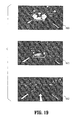
- FIG. 19 shows the stop and go scenario, where the leading vehicle was detected stopped at an intersection and then slowly accelerating and leaving the intersection.
- FIG. 19 has 3 images: 1900 , 1901 and 1902 representing individual frames out of a series of 338 frames.
- Image 1900 shows frame 91 of 338 with a leading vehicle with brake lights turned on at a full stop at an intersection.
- Image 1901 shows frame 112 of 338 with the leading car driving off, still having brake lights on.
- image 1902 is frame 211 of 338 frames with the leading car leaving the intersection.
- Various illumination patterns caused by taillights, brake lights, reflections as well as other light sources such as road lamps, vehicle head lights and reflection on road signs are observed. The method was able to detect and track the leading vehicle in a reasonable distance range.
- a new vision algorithm is provided to detect and track a leading vehicle at night time, which can be applied in a context adaptive approach in vehicle detection under various visibility conditions.
- the detection algorithm follows a hypothesis generation and hypothesis verification approach to identify pairs of taillights and brake lights using multiple constraints learned or derived from vehicle lights and geometry.
- the tracking algorithm tracks the target vehicle through a combination of offline and online models which effectively exploit the general information of all vehicle lights as well as specific information of the particular target obtained online. This method has demonstrated to be effective in detecting and tracking leading vehicles in real scenarios.
Landscapes
- Engineering & Computer Science (AREA)
- Physics & Mathematics (AREA)
- General Physics & Mathematics (AREA)
- Multimedia (AREA)
- Theoretical Computer Science (AREA)
- Image Analysis (AREA)
- Traffic Control Systems (AREA)
Abstract
Description
- Given: N patterns to be clustered
- Choose k cluster seeds, to coincide with k patterns chosen to represent a variety of lighting conditions
- Repeat
-
- Recompute the cluster centers using the current
- cluster membership
- until the convergence criteria is met
- return the k centers from last iteration
where Hi,j denotes the jth bin of the histogram Hi and Nb denotes the number of bins. The distance measure is bounded, i.e. 0≦DB(H1,H2)≦1. Note DB(H1,H2)=1 when there is no overlapping between H1 and H2, and DB(H1,H2)=0 when H1 and H2 are identical. Other alternatives can be considered, such as the Euclidean or Wasserstein distances.
- Cluster 1: Images of Night Condition.
- Cluster 6, cluster 9, cluster 13,
cluster 2, cluster 5, cluster 3: Images of Low Light Condition. They typically include images of dusk, dawn, or in tunnels with low ambient lights. - Cluster 7, cluster 8,
cluster 10, cluster 11, cluster 12: Image of Day Light Condition. They typically include images captured during day time with bright ambient lights. - Cluster 4: Saturated images.
where I denotes an image sample being classified, N denotes the number of boosting rounds performed, hi denotes the i-th weak classifier (hi(I)ε{−1,+1}), and αi denotes its weight. The final decision sign[H(I)] on an image patch depends on the weighted votes from the weak classifiers. The classification label assigned to the image I is sign[H(I)]. AdaBoost is an iterative learning algorithm where training samples are re-weighted and a series of new weak classifiers are learned. In each iteration a weak classifier that best discriminates the weighted samples is chosen. The weight αi of the resulting weak classifier is determined by the classification error. The sample distribution is then modified by increasing the weights of the misclassified samples and decreasing the weights of samples classified correctly. This allows weak classifiers focusing on the previously misclassified examples to be selected.
By varying the size (i.e. width and height) of the masks, one obtains a number of tail-light features.
-
- A Low Light classifier trained with the set of Low Light training samples
- A Daylight classifier trained with the set of Daylight training samples
- A non-specialized classifier trained with the whole set of training samples
In each classifier trained with the AdaBoost algorithm, 250 features were used. The flow of this process is shown inFIG. 6 . To evaluate the performance of the context-adaptive classification, the error rate of the non-specialized classifier (named ALL) were compared with the error rate of the context-adaptive detector over all the testing data. The error rate of the context-adaptive detector is calculated by accumulating the error of the two specialized classifiers in their respective context. The flow of the testing process is shown inFIG. 7 .
| TABLE 1 | ||
| Average Number of False Alarms | ||
| True | ALL | LL | DL |
| Det. | non- | non- | non- | |||
| Rates | adapt. | adapt. | adapt. | adapt. | adapt. | adapt. |
| 1.000 | 311.5 | 274.4 | 368.4 | 331.8 | 27.4 | 5.4 |
| 0.999 | 196.8 | 166.0 | 224.0 | 199.2 | 13.4 | 1.6 |
| 0.998 | 119.8 | 84.6 | 158.0 | 140.8 | 7.2 | 1.2 |
| 0.997 | 89.8 | 58.0 | 85.6 | 77.8 | 5.4 | 0.8 |
| 0.996 | 70.2 | 47.6 | 76.0 | 66.4 | 3.2 | 0.8 |
| 0.995 | 53.2 | 34.4 | 63.4 | 48.6 | 2.6 | 0.8 |
| 0.990 | 23.0 | 10.8 | 27.4 | 20.8 | 0.6 | 0.6 |
| 0.985 | 15.2 | 5.8 | 16.6 | 9.2 | 0.4 | 0.6 |
| 0.980 | 10.8 | 3.6 | 12.4 | 6.2 | 0.2 | 0.6 |
| 0.970 | 5.6 | 2.2 | 5.8 | 2.8 | 0.2 | 0.4 |
| TABLE 2 | ||
| Average Number | ||
| of Test Samples | ||
| LL | DL | ALL | ||
| vehicles | 754.8 | 492.4 | 1247.2 | ||
| non-vehicles | 1713.6 | 1544.2 | 3257.8 | ||
In
| TABLE 3 | |||||||
| Low Light | Daylight | Combined | |||||
| Threshold | Fa/Fr | Td | Fa/Fr | Td | Fa/Fr | Td |
| −0.04 | 1.30 | 1.00 | 1.80 | 1.00 | 1.55 | 1.00 |
| −0.02 | 0.40 | 1.00 | 1.00 | 1.00 | 0.70 | 1.00 |
| 0.00 | 0.10 | 1.00 | 0.50 | 1.00 | 0.30 | 1.00 |
| 0.02 | 0.10 | 0.94 | 0.20 | 1.00 | 0.15 | 0.97 |
| 0.04 | 0.10 | 0.89 | 0.00 | 1.00 | 0.05 | 0.94 |
| 0.06 | 0.00 | 0.78 | 0.00 | 0.94 | 0.00 | 0.86 |
T≦I(x 0)≦I(x 0+1)≦ . . . ≦I(x 0 +m)
I(x 0 +m)≧(x 0 +m+1)≧ . . . ≧I(x 0 +N)≧T
with m<N.
The median operator is used for robustness against short and fragmented illumination lines.
{I(x,y):x=1, . . . M,y=1, . . . N;I(x,y)=0 or 1}.
The probabilistic template is defined as a naïve Bayes
The probability term P(I(x,y)=1) is learned from vehicle examples.
where I(u,v) denotes a pixel value in the testing image, T(u,v) denotes a pixel value in a static template, |.| denotes the number of elements, and τ(u,v) denotes the transformation (scaling and translation) that maps an image region to the size of the template. A hypothesis is accepted if the matching score is above a threshold and rejected otherwise.
are the minimal and maximal image width of a vehicle whose vertical location in the image plane is
These parameters can be pre-calculated through perspective transformations. The first constraint on |yr−yl| states that the two taillights should be vertically aligned. The constraints on the horizontal spacing between two taillights |xr−xl| comply with the perspective geometry.
Claims (21)
Priority Applications (1)
| Application Number | Priority Date | Filing Date | Title |
|---|---|---|---|
| US11/825,619 US7724962B2 (en) | 2006-07-07 | 2007-07-05 | Context adaptive approach in vehicle detection under various visibility conditions |
Applications Claiming Priority (2)
| Application Number | Priority Date | Filing Date | Title |
|---|---|---|---|
| US81942306P | 2006-07-07 | 2006-07-07 | |
| US11/825,619 US7724962B2 (en) | 2006-07-07 | 2007-07-05 | Context adaptive approach in vehicle detection under various visibility conditions |
Publications (2)
| Publication Number | Publication Date |
|---|---|
| US20080069400A1 US20080069400A1 (en) | 2008-03-20 |
| US7724962B2 true US7724962B2 (en) | 2010-05-25 |
Family
ID=39188654
Family Applications (1)
| Application Number | Title | Priority Date | Filing Date |
|---|---|---|---|
| US11/825,619 Expired - Fee Related US7724962B2 (en) | 2006-07-07 | 2007-07-05 | Context adaptive approach in vehicle detection under various visibility conditions |
Country Status (1)
| Country | Link |
|---|---|
| US (1) | US7724962B2 (en) |
Cited By (42)
| Publication number | Priority date | Publication date | Assignee | Title |
|---|---|---|---|---|
| US20100202662A1 (en) * | 2009-02-12 | 2010-08-12 | Laser Technology, Inc. | Vehicle classification by image processing with laser range finder |
| US20100278392A1 (en) * | 2008-02-13 | 2010-11-04 | Honda Motor Co., Ltd. | Vehicle periphery monitoring device, vehicle, and vehicle periphery monitoring program |
| US20100295705A1 (en) * | 2007-10-25 | 2010-11-25 | Adc Automotive Distance Control Systems Gmbh | Method for distinguishing between reflectors arranged on the roadside and vehicle lights in the dark |
| US20100329544A1 (en) * | 2009-06-30 | 2010-12-30 | Sony Corporation | Information processing apparatus, information processing method, and program |
| US20110093416A1 (en) * | 2008-10-03 | 2011-04-21 | Pelossof Raphael A | Systems, Methods, and Media for Performing Classification |
| US20110211071A1 (en) * | 2007-08-28 | 2011-09-01 | Valeo Schalter Und Sensoren Gmbh | Method and system for evaluating brightness values in sensor images of image-evaluating adaptive cruise control systems, especially with respect to day/night distinction |
| US20110293140A1 (en) * | 2010-05-28 | 2011-12-01 | Qualcomm Incorporated | Dataset Creation For Tracking Targets With Dynamically Changing Portions |
| US20120201436A1 (en) * | 2011-02-03 | 2012-08-09 | Jonathan Oakley | Method and system for image analysis and interpretation |
| US20140379233A1 (en) * | 2013-06-19 | 2014-12-25 | Magna Electronics Inc. | Vehicle vision system with collision mitigation |
| US20150098616A1 (en) * | 2013-10-03 | 2015-04-09 | Qualcomm Incorporated | Object recognition and map generation with environment references |
| DE102014106506A1 (en) | 2014-05-08 | 2015-11-12 | Valeo Schalter Und Sensoren Gmbh | Method for carrying out a diagnosis of a camera system of a motor vehicle, camera system and motor vehicle |
| US9327693B2 (en) | 2013-04-10 | 2016-05-03 | Magna Electronics Inc. | Rear collision avoidance system for vehicle |
| US9481301B2 (en) | 2012-12-05 | 2016-11-01 | Magna Electronics Inc. | Vehicle vision system utilizing camera synchronization |
| US9547795B2 (en) | 2011-04-25 | 2017-01-17 | Magna Electronics Inc. | Image processing method for detecting objects using relative motion |
| US9619716B2 (en) | 2013-08-12 | 2017-04-11 | Magna Electronics Inc. | Vehicle vision system with image classification |
| US9623878B2 (en) | 2014-04-02 | 2017-04-18 | Magna Electronics Inc. | Personalized driver assistance system for vehicle |
| US9681062B2 (en) | 2011-09-26 | 2017-06-13 | Magna Electronics Inc. | Vehicle camera image quality improvement in poor visibility conditions by contrast amplification |
| US9686451B2 (en) | 2015-01-21 | 2017-06-20 | Toyota Jidosha Kabushiki Kaisha | Real time driving difficulty categorization |
| US9743002B2 (en) | 2012-11-19 | 2017-08-22 | Magna Electronics Inc. | Vehicle vision system with enhanced display functions |
| US9751465B2 (en) | 2012-04-16 | 2017-09-05 | Magna Electronics Inc. | Vehicle vision system with reduced image color data processing by use of dithering |
| US9900490B2 (en) | 2011-09-21 | 2018-02-20 | Magna Electronics Inc. | Vehicle vision system using image data transmission and power supply via a coaxial cable |
| US9925980B2 (en) | 2014-09-17 | 2018-03-27 | Magna Electronics Inc. | Vehicle collision avoidance system with enhanced pedestrian avoidance |
| US9988047B2 (en) | 2013-12-12 | 2018-06-05 | Magna Electronics Inc. | Vehicle control system with traffic driving control |
| US10025994B2 (en) | 2012-12-04 | 2018-07-17 | Magna Electronics Inc. | Vehicle vision system utilizing corner detection |
| US10027930B2 (en) | 2013-03-29 | 2018-07-17 | Magna Electronics Inc. | Spectral filtering for vehicular driver assistance systems |
| US10081308B2 (en) | 2011-07-08 | 2018-09-25 | Bendix Commercial Vehicle Systems Llc | Image-based vehicle detection and distance measuring method and apparatus |
| US10089537B2 (en) | 2012-05-18 | 2018-10-02 | Magna Electronics Inc. | Vehicle vision system with front and rear camera integration |
| US10144419B2 (en) | 2015-11-23 | 2018-12-04 | Magna Electronics Inc. | Vehicle dynamic control system for emergency handling |
| US10232797B2 (en) | 2013-04-29 | 2019-03-19 | Magna Electronics Inc. | Rear vision system for vehicle with dual purpose signal lines |
| US10248874B2 (en) | 2016-11-22 | 2019-04-02 | Ford Global Technologies, Llc | Brake light detection |
| US10286855B2 (en) | 2015-03-23 | 2019-05-14 | Magna Electronics Inc. | Vehicle vision system with video compression |
| US10326969B2 (en) | 2013-08-12 | 2019-06-18 | Magna Electronics Inc. | Vehicle vision system with reduction of temporal noise in images |
| US10523904B2 (en) | 2013-02-04 | 2019-12-31 | Magna Electronics Inc. | Vehicle data recording system |
| US10567705B2 (en) | 2013-06-10 | 2020-02-18 | Magna Electronics Inc. | Coaxial cable with bidirectional data transmission |
| US10609335B2 (en) | 2012-03-23 | 2020-03-31 | Magna Electronics Inc. | Vehicle vision system with accelerated object confirmation |
| US10607094B2 (en) | 2017-02-06 | 2020-03-31 | Magna Electronics Inc. | Vehicle vision system with traffic sign recognition |
| US10640040B2 (en) | 2011-11-28 | 2020-05-05 | Magna Electronics Inc. | Vision system for vehicle |
| US10819943B2 (en) | 2015-05-07 | 2020-10-27 | Magna Electronics Inc. | Vehicle vision system with incident recording function |
| US11507779B1 (en) * | 2020-07-24 | 2022-11-22 | Norfolk Southern Corporation | Two-stage deep learning framework for detecting the condition of rail car coupler systems |
| US20220392247A1 (en) * | 2019-11-18 | 2022-12-08 | Positive One Corporation | Assignment control apparatus, assignment control system, and assignment control method |
| US11816842B2 (en) | 2020-03-05 | 2023-11-14 | Alibaba Group Holding Limited | Image processing method, apparatus, electronic device, and storage medium |
| US11968639B2 (en) | 2020-11-11 | 2024-04-23 | Magna Electronics Inc. | Vehicular control system with synchronized communication between control units |
Families Citing this family (56)
| Publication number | Priority date | Publication date | Assignee | Title |
|---|---|---|---|---|
| US7466841B2 (en) * | 2004-08-16 | 2008-12-16 | Siemens Corporate Research, Inc. | Method for traffic sign detection |
| US9569531B2 (en) * | 2008-06-23 | 2017-02-14 | Sri International | System and method for multi-agent event detection and recognition |
| US8452599B2 (en) * | 2009-06-10 | 2013-05-28 | Toyota Motor Engineering & Manufacturing North America, Inc. | Method and system for extracting messages |
| US8269616B2 (en) * | 2009-07-16 | 2012-09-18 | Toyota Motor Engineering & Manufacturing North America, Inc. | Method and system for detecting gaps between objects |
| EP2306366A1 (en) | 2009-10-01 | 2011-04-06 | Autoliv Development AB | Vision system and method for a motor vehicle |
| US8337160B2 (en) * | 2009-10-19 | 2012-12-25 | Toyota Motor Engineering & Manufacturing North America, Inc. | High efficiency turbine system |
| US8237792B2 (en) * | 2009-12-18 | 2012-08-07 | Toyota Motor Engineering & Manufacturing North America, Inc. | Method and system for describing and organizing image data |
| EP2385482B1 (en) * | 2010-05-05 | 2016-04-20 | Autoliv Development AB | A driver assisting system and method for a motor vehicle |
| US8494808B2 (en) | 2010-05-17 | 2013-07-23 | The Johns Hopkins University | Method for optimizing parameters for detection systems |
| US8424621B2 (en) | 2010-07-23 | 2013-04-23 | Toyota Motor Engineering & Manufacturing North America, Inc. | Omni traction wheel system and methods of operating the same |
| JP5591613B2 (en) * | 2010-07-27 | 2014-09-17 | 株式会社小糸製作所 | Vehicle detection device |
| JP2014515847A (en) * | 2011-03-25 | 2014-07-03 | ティーケー ホールディングス インク. | Driver alertness determination system and method |
| US20150035979A1 (en) * | 2011-05-26 | 2015-02-05 | Conti Temic Microelectronic Gmbh | Method for deriving environmental information from detecting the rear lights of preceding vehicles |
| CA2780595A1 (en) * | 2011-06-22 | 2012-12-22 | Roman Palenychka | Method and multi-scale attention system for spatiotemporal change determination and object detection |
| JP5518007B2 (en) | 2011-07-11 | 2014-06-11 | クラリオン株式会社 | Vehicle external recognition device and vehicle control system using the same |
| JP5690688B2 (en) * | 2011-09-15 | 2015-03-25 | クラリオン株式会社 | Outside world recognition method, apparatus, and vehicle system |
| US9635271B2 (en) * | 2011-11-17 | 2017-04-25 | GM Global Technology Operations LLC | Vision-based scene detection |
| JP2013200603A (en) * | 2012-03-23 | 2013-10-03 | Hitachi Automotive Systems Ltd | In-vehicle image processing device and method |
| US9129159B2 (en) | 2012-06-05 | 2015-09-08 | Xerox Corporation | Vehicle headlight state monitoring methods, systems and processor-readable media |
| KR101382873B1 (en) * | 2012-06-29 | 2014-04-08 | 엘지이노텍 주식회사 | Forward Collision Warning System and Forward Collision Warning Method |
| US8971573B2 (en) * | 2012-09-12 | 2015-03-03 | Xerox Corporation | Video-tracking for video-based speed enforcement |
| US10678259B1 (en) * | 2012-09-13 | 2020-06-09 | Waymo Llc | Use of a reference image to detect a road obstacle |
| US9445011B2 (en) * | 2012-10-22 | 2016-09-13 | GM Global Technology Operations LLC | Dynamic rearview mirror adaptive dimming overlay through scene brightness estimation |
| US10013477B2 (en) * | 2012-11-19 | 2018-07-03 | The Penn State Research Foundation | Accelerated discrete distribution clustering under wasserstein distance |
| CN104182958B (en) * | 2013-05-21 | 2019-01-08 | 索尼公司 | Object detection method and device |
| DE102013012781A1 (en) * | 2013-07-31 | 2015-02-05 | Connaught Electronics Ltd. | Method for training an algorithm for recognizing predetermined patterns in image data, camera system and motor vehicle |
| KR101498975B1 (en) * | 2013-11-29 | 2015-03-05 | 현대모비스(주) | Lane Departure Warning System |
| CN105981042B (en) * | 2014-01-17 | 2019-12-06 | Kpit技术有限责任公司 | Vehicle detection system and method |
| EP2913993B1 (en) | 2014-02-26 | 2016-02-17 | Axis AB | Method and control unit for controlling exposure of a camera |
| CN103942541A (en) * | 2014-04-11 | 2014-07-23 | 浙江大学 | Electric vehicle automatic detection method based on vehicle-mounted vision within blind zone |
| US9568611B2 (en) * | 2014-08-20 | 2017-02-14 | Nec Corporation | Detecting objects obstructing a driver's view of a road |
| US9443320B1 (en) * | 2015-05-18 | 2016-09-13 | Xerox Corporation | Multi-object tracking with generic object proposals |
| US9669833B2 (en) * | 2015-07-21 | 2017-06-06 | GM Global Technology Operations LLC | Method and system for operating adaptive cruise control system |
| US9946951B2 (en) * | 2015-08-12 | 2018-04-17 | International Business Machines Corporation | Self-optimized object detection using online detector selection |
| ITUB20154942A1 (en) * | 2015-10-23 | 2017-04-23 | Magneti Marelli Spa | Method to detect an incoming vehicle and its system |
| CN105718893B (en) * | 2016-01-22 | 2019-01-08 | 江苏大学 | A kind of light for vehicle for night-environment is to detection method |
| US9911055B2 (en) * | 2016-03-08 | 2018-03-06 | Conduent Business Services, Llc | Method and system for detection and classification of license plates |
| US20190122059A1 (en) * | 2016-03-31 | 2019-04-25 | Agency For Science, Technology And Research | Signal light detection |
| CN106529424B (en) * | 2016-10-20 | 2019-01-04 | 中山大学 | A kind of logo detection recognition method and system based on selective search algorithm |
| JP2018081404A (en) * | 2016-11-15 | 2018-05-24 | パナソニック インテレクチュアル プロパティ コーポレーション オブ アメリカPanasonic Intellectual Property Corporation of America | Discrimination method, discrimination device, discriminator generation method and discriminator generation device |
| US10185881B2 (en) * | 2016-11-23 | 2019-01-22 | Ford Global Technologies, Llc | Traffic-light detection and classification using computer vision and deep learning |
| WO2018183221A1 (en) | 2017-03-28 | 2018-10-04 | Hrl Laboratories, Llc | Machine-vision method to classify input data based on object components |
| DE102017215051A1 (en) * | 2017-08-29 | 2019-02-28 | Conti Temic Microelectronic Gmbh | Apparatus and method for reducing the influence of stray light and reflections on optical image recognition |
| DE102017215050A1 (en) * | 2017-08-29 | 2019-02-28 | Conti Temic Microelectronic Gmbh | Apparatus and method for reducing the influence of shadows and low contrast on optical image recognition |
| US10733465B2 (en) | 2017-09-20 | 2020-08-04 | Tusimple, Inc. | System and method for vehicle taillight state recognition |
| US10908614B2 (en) | 2017-12-19 | 2021-02-02 | Here Global B.V. | Method and apparatus for providing unknown moving object detection |
| US10467486B2 (en) * | 2017-12-29 | 2019-11-05 | Automotive Research & Testing Center | Method for evaluating credibility of obstacle detection |
| JP7316731B2 (en) * | 2018-06-06 | 2023-07-28 | コグネックス・コーポレイション | Systems and methods for detecting and classifying patterns in images in vision systems |
| CN110930429B (en) * | 2018-09-19 | 2023-03-31 | 杭州海康威视数字技术股份有限公司 | Target tracking processing method, device and equipment and readable medium |
| IN201921008342A (en) * | 2019-03-04 | 2019-03-15 | ||
| WO2020178667A1 (en) * | 2019-03-04 | 2020-09-10 | Kpit Technologies Limited | System and method for day and night time vehicle detection |
| GB2585005B (en) * | 2019-06-24 | 2021-06-23 | Roadmetric Ltd | Training a machine to recognize a motor vehicle driver using a mobile device |
| KR102319650B1 (en) * | 2020-07-28 | 2021-10-29 | 숭실대학교산학협력단 | Apparatus and method for pairing vehicle light |
| CN111931745B (en) * | 2020-10-09 | 2021-01-12 | 蘑菇车联信息科技有限公司 | Vehicle detection method and device, electronic equipment and storage medium |
| CN112287808B (en) * | 2020-10-27 | 2021-08-10 | 江苏云从曦和人工智能有限公司 | Motion trajectory analysis warning method, device, system and storage medium |
| CN112348116B (en) * | 2020-11-30 | 2024-02-02 | 长沙理工大学 | Target detection method and device using space context and computer equipment |
Citations (5)
| Publication number | Priority date | Publication date | Assignee | Title |
|---|---|---|---|---|
| US5809161A (en) * | 1992-03-20 | 1998-09-15 | Commonwealth Scientific And Industrial Research Organisation | Vehicle monitoring system |
| US20060088207A1 (en) * | 2004-10-22 | 2006-04-27 | Henry Schneiderman | Object recognizer and detector for two-dimensional images using bayesian network based classifier |
| US20070005356A1 (en) * | 2005-06-30 | 2007-01-04 | Florent Perronnin | Generic visual categorization method and system |
| US20070014480A1 (en) * | 2005-07-13 | 2007-01-18 | General Electric Company | Method and apparatus for creating a multi-resolution framework for improving medical imaging workflow |
| US20070291984A1 (en) * | 2006-06-15 | 2007-12-20 | Omron Corporation | Robust object tracking system |
-
2007
- 2007-07-05 US US11/825,619 patent/US7724962B2/en not_active Expired - Fee Related
Patent Citations (5)
| Publication number | Priority date | Publication date | Assignee | Title |
|---|---|---|---|---|
| US5809161A (en) * | 1992-03-20 | 1998-09-15 | Commonwealth Scientific And Industrial Research Organisation | Vehicle monitoring system |
| US20060088207A1 (en) * | 2004-10-22 | 2006-04-27 | Henry Schneiderman | Object recognizer and detector for two-dimensional images using bayesian network based classifier |
| US20070005356A1 (en) * | 2005-06-30 | 2007-01-04 | Florent Perronnin | Generic visual categorization method and system |
| US20070014480A1 (en) * | 2005-07-13 | 2007-01-18 | General Electric Company | Method and apparatus for creating a multi-resolution framework for improving medical imaging workflow |
| US20070291984A1 (en) * | 2006-06-15 | 2007-12-20 | Omron Corporation | Robust object tracking system |
Non-Patent Citations (11)
| Title |
|---|
| Cabani, Iyadh et al., "Color-Based Detection of Vehicle Lights", Intelligent Vehicles Symposium, 2005. Proceedings. IEEE, (Jun. 2005),278-283. |
| Cucchiara, Rita et al., "Image Analysis and Rule-Based Reasoning for a Traffic Monitoring System", IEEE Transactions on Intelligent Transportation Systems, vol. 1, No. 2, (Jun. 2000),119-130. |
| Deselaers, Features for image retrieval, Dec. 2003, Lehrstuhlf'ur Informatik VI, RWTH Aachen University, Aachen, Germany, pp. 35,37. * |
| Jain, A. K., et al., "Data Clustering: A Review", ACM Computing Surveys, vol. 31, No. 3, (1999),264-323. |
| Kim, Samyong et al., "Front and Rear Vehicle Detection and Tracking in the Day and Night Times Using Vision and Sonar Sensor Fusion", Intelligent Robots and Systems, 2005. (IROS 2005). IEEE/RSJ International Conference, (Aug. 2-6, 2007),2173-2178. |
| Schapire, Robert E., et al., "Improved Boosting Algorithms Using Confidence-rated Predictions", Machine Learning, 37(3):297-336, (1999),1-40. |
| Song, Kai-Tai et al., "Front Vehicle Tracking Using Scene Analysis", Mechatronics and Automation, 2005 IEEE International Conference vol. 3, (2005), 1323-1328. |
| Sun, Zehang et al., "On-Road Vehicle Detection: A Review", IEEE Transactions on Pattern Analysis and Machine Intelligence, vol. 28, No. 5, (May 2005),694-711. |
| Viola, Paul et al., "Rapid Object Detection using a Boosted Cascade of Simple Features", Accepted Conference on Computer Vision and Pattern Recognition, (2001),1-9. |
| Zhu, Ying et al., "An Integrated Framework of Vision-Based Vehicle With Knowledge of Fusion", Intelligent Vehicles Symposium, 2005. Proceedings. IEEE(Jun. 6-8, 2005), 199-204. |
| Zhu, Ying et al., "Reliable Detection of Overtaking Vehicles Using Robust Information Fusion", IEEE Transactions on Intelligent Transportation Systems, vol. 7, No. 4, (Dec. 2006),401-414. |
Cited By (107)
| Publication number | Priority date | Publication date | Assignee | Title |
|---|---|---|---|---|
| US8823799B2 (en) | 2007-08-28 | 2014-09-02 | Bendix Commercial Vehicle Systems Llc | Method and system for evaluating brightness values in sensor images of image-evaluating adaptive cruise control systems, especially with respect to day/night distinction |
| US20110211071A1 (en) * | 2007-08-28 | 2011-09-01 | Valeo Schalter Und Sensoren Gmbh | Method and system for evaluating brightness values in sensor images of image-evaluating adaptive cruise control systems, especially with respect to day/night distinction |
| US20100295705A1 (en) * | 2007-10-25 | 2010-11-25 | Adc Automotive Distance Control Systems Gmbh | Method for distinguishing between reflectors arranged on the roadside and vehicle lights in the dark |
| US8587456B2 (en) * | 2007-10-25 | 2013-11-19 | Adc Automotive Distance Control Systems Gmbh | Method for distinguishing between reflectors arranged on the roadside and vehicle lights in the dark |
| US20100278392A1 (en) * | 2008-02-13 | 2010-11-04 | Honda Motor Co., Ltd. | Vehicle periphery monitoring device, vehicle, and vehicle periphery monitoring program |
| US7974445B2 (en) * | 2008-02-13 | 2011-07-05 | Honda Motor Co., Ltd. | Vehicle periphery monitoring device, vehicle, and vehicle periphery monitoring program |
| US20110093416A1 (en) * | 2008-10-03 | 2011-04-21 | Pelossof Raphael A | Systems, Methods, and Media for Performing Classification |
| US8909572B2 (en) | 2008-10-03 | 2014-12-09 | The Trustees Of Columbia University In The City Of New York | Systems, methods, and media for performing classification using a boosted classifier |
| US20100202662A1 (en) * | 2009-02-12 | 2010-08-12 | Laser Technology, Inc. | Vehicle classification by image processing with laser range finder |
| US8311343B2 (en) * | 2009-02-12 | 2012-11-13 | Laser Technology, Inc. | Vehicle classification by image processing with laser range finder |
| US20100329544A1 (en) * | 2009-06-30 | 2010-12-30 | Sony Corporation | Information processing apparatus, information processing method, and program |
| US8401283B2 (en) * | 2009-06-30 | 2013-03-19 | Sony Corporation | Information processing apparatus, information processing method, and program |
| US20160098600A1 (en) * | 2010-05-28 | 2016-04-07 | Qualcomm Incorporated | Dataset creation for tracking targets with dynamically changing portions |
| US20110293140A1 (en) * | 2010-05-28 | 2011-12-01 | Qualcomm Incorporated | Dataset Creation For Tracking Targets With Dynamically Changing Portions |
| US9256956B2 (en) * | 2010-05-28 | 2016-02-09 | Qualcomm Incorporated | Dataset creation for tracking targets with dynamically changing portions |
| US9785836B2 (en) * | 2010-05-28 | 2017-10-10 | Qualcomm Incorporated | Dataset creation for tracking targets with dynamically changing portions |
| US8989514B2 (en) * | 2011-02-03 | 2015-03-24 | Voxeleron Llc | Method and system for image analysis and interpretation |
| US20120201436A1 (en) * | 2011-02-03 | 2012-08-09 | Jonathan Oakley | Method and system for image analysis and interpretation |
| US9710888B2 (en) | 2011-02-03 | 2017-07-18 | Voxeleron Llc | Method and system for image analysis and interpretation |
| US9547795B2 (en) | 2011-04-25 | 2017-01-17 | Magna Electronics Inc. | Image processing method for detecting objects using relative motion |
| US10043082B2 (en) | 2011-04-25 | 2018-08-07 | Magna Electronics Inc. | Image processing method for detecting objects using relative motion |
| US10452931B2 (en) | 2011-04-25 | 2019-10-22 | Magna Electronics Inc. | Processing method for distinguishing a three dimensional object from a two dimensional object using a vehicular system |
| US10081308B2 (en) | 2011-07-08 | 2018-09-25 | Bendix Commercial Vehicle Systems Llc | Image-based vehicle detection and distance measuring method and apparatus |
| US10284764B2 (en) | 2011-09-21 | 2019-05-07 | Magna Electronics Inc. | Vehicle vision using image data transmission and power supply via a coaxial cable |
| US10567633B2 (en) | 2011-09-21 | 2020-02-18 | Magna Electronics Inc. | Vehicle vision system using image data transmission and power supply via a coaxial cable |
| US11877054B2 (en) | 2011-09-21 | 2024-01-16 | Magna Electronics Inc. | Vehicular vision system using image data transmission and power supply via a coaxial cable |
| US11201994B2 (en) | 2011-09-21 | 2021-12-14 | Magna Electronics Inc. | Vehicular multi-camera surround view system using image data transmission and power supply via coaxial cables |
| US9900490B2 (en) | 2011-09-21 | 2018-02-20 | Magna Electronics Inc. | Vehicle vision system using image data transmission and power supply via a coaxial cable |
| US10827108B2 (en) | 2011-09-21 | 2020-11-03 | Magna Electronics Inc. | Vehicular vision system using image data transmission and power supply via a coaxial cable |
| US11638070B2 (en) | 2011-09-21 | 2023-04-25 | Magna Electronics Inc. | Vehicular vision system using image data transmission and power supply via a coaxial cable |
| US9774790B1 (en) | 2011-09-26 | 2017-09-26 | Magna Electronics Inc. | Method for enhancing vehicle camera image quality |
| US10257432B2 (en) | 2011-09-26 | 2019-04-09 | Magna Electronics Inc. | Method for enhancing vehicle camera image quality |
| US9681062B2 (en) | 2011-09-26 | 2017-06-13 | Magna Electronics Inc. | Vehicle camera image quality improvement in poor visibility conditions by contrast amplification |
| US10640040B2 (en) | 2011-11-28 | 2020-05-05 | Magna Electronics Inc. | Vision system for vehicle |
| US11142123B2 (en) | 2011-11-28 | 2021-10-12 | Magna Electronics Inc. | Multi-camera vehicular vision system |
| US11634073B2 (en) | 2011-11-28 | 2023-04-25 | Magna Electronics Inc. | Multi-camera vehicular vision system |
| US10911721B2 (en) | 2012-03-23 | 2021-02-02 | Magna Electronics Inc. | Vehicle vision system with accelerated determination of an object of interest |
| US10609335B2 (en) | 2012-03-23 | 2020-03-31 | Magna Electronics Inc. | Vehicle vision system with accelerated object confirmation |
| US11627286B2 (en) | 2012-03-23 | 2023-04-11 | Magna Electronics Inc. | Vehicular vision system with accelerated determination of another vehicle |
| US11184585B2 (en) | 2012-03-23 | 2021-11-23 | Magna Electronics Inc. | Vehicular vision system with accelerated determination of an object of interest |
| US9751465B2 (en) | 2012-04-16 | 2017-09-05 | Magna Electronics Inc. | Vehicle vision system with reduced image color data processing by use of dithering |
| US10434944B2 (en) | 2012-04-16 | 2019-10-08 | Magna Electronics Inc. | Vehicle vision system with reduced image color data processing by use of dithering |
| US11769335B2 (en) | 2012-05-18 | 2023-09-26 | Magna Electronics Inc. | Vehicular rear backup system |
| US10922563B2 (en) | 2012-05-18 | 2021-02-16 | Magna Electronics Inc. | Vehicular control system |
| US10515279B2 (en) | 2012-05-18 | 2019-12-24 | Magna Electronics Inc. | Vehicle vision system with front and rear camera integration |
| US10089537B2 (en) | 2012-05-18 | 2018-10-02 | Magna Electronics Inc. | Vehicle vision system with front and rear camera integration |
| US11508160B2 (en) | 2012-05-18 | 2022-11-22 | Magna Electronics Inc. | Vehicular vision system |
| US11308718B2 (en) | 2012-05-18 | 2022-04-19 | Magna Electronics Inc. | Vehicular vision system |
| US10104298B2 (en) | 2012-11-19 | 2018-10-16 | Magna Electronics Inc. | Vehicle vision system with enhanced display functions |
| US9743002B2 (en) | 2012-11-19 | 2017-08-22 | Magna Electronics Inc. | Vehicle vision system with enhanced display functions |
| US10321064B2 (en) | 2012-11-19 | 2019-06-11 | Magna Electronics Inc. | Vehicular vision system with enhanced display functions |
| US10025994B2 (en) | 2012-12-04 | 2018-07-17 | Magna Electronics Inc. | Vehicle vision system utilizing corner detection |
| US10873682B2 (en) | 2012-12-05 | 2020-12-22 | Magna Electronics Inc. | Method of synchronizing multiple vehicular cameras with an ECU |
| US9481301B2 (en) | 2012-12-05 | 2016-11-01 | Magna Electronics Inc. | Vehicle vision system utilizing camera synchronization |
| US9912841B2 (en) | 2012-12-05 | 2018-03-06 | Magna Electronics Inc. | Vehicle vision system utilizing camera synchronization |
| US10171709B2 (en) | 2012-12-05 | 2019-01-01 | Magna Electronics Inc. | Vehicle vision system utilizing multiple cameras and ethernet links |
| US10560610B2 (en) | 2012-12-05 | 2020-02-11 | Magna Electronics Inc. | Method of synchronizing multiple vehicular cameras with an ECU |
| US11012668B2 (en) | 2013-02-04 | 2021-05-18 | Magna Electronics Inc. | Vehicular security system that limits vehicle access responsive to signal jamming detection |
| US10523904B2 (en) | 2013-02-04 | 2019-12-31 | Magna Electronics Inc. | Vehicle data recording system |
| US10027930B2 (en) | 2013-03-29 | 2018-07-17 | Magna Electronics Inc. | Spectral filtering for vehicular driver assistance systems |
| US10875527B2 (en) | 2013-04-10 | 2020-12-29 | Magna Electronics Inc. | Collision avoidance system for vehicle |
| US9545921B2 (en) | 2013-04-10 | 2017-01-17 | Magna Electronics Inc. | Collision avoidance system for vehicle |
| US9802609B2 (en) | 2013-04-10 | 2017-10-31 | Magna Electronics Inc. | Collision avoidance system for vehicle |
| US11485358B2 (en) | 2013-04-10 | 2022-11-01 | Magna Electronics Inc. | Vehicular collision avoidance system |
| US10207705B2 (en) | 2013-04-10 | 2019-02-19 | Magna Electronics Inc. | Collision avoidance system for vehicle |
| US9327693B2 (en) | 2013-04-10 | 2016-05-03 | Magna Electronics Inc. | Rear collision avoidance system for vehicle |
| US11718291B2 (en) | 2013-04-10 | 2023-08-08 | Magna Electronics Inc. | Vehicular collision avoidance system |
| US10232797B2 (en) | 2013-04-29 | 2019-03-19 | Magna Electronics Inc. | Rear vision system for vehicle with dual purpose signal lines |
| US11533452B2 (en) | 2013-06-10 | 2022-12-20 | Magna Electronics Inc. | Vehicular multi-camera vision system using coaxial cables with bidirectional data transmission |
| US11290679B2 (en) | 2013-06-10 | 2022-03-29 | Magna Electronics Inc. | Vehicular multi-camera vision system using coaxial cables with bidirectional data transmission |
| US11025859B2 (en) | 2013-06-10 | 2021-06-01 | Magna Electronics Inc. | Vehicular multi-camera vision system using coaxial cables with bidirectional data transmission |
| US10567705B2 (en) | 2013-06-10 | 2020-02-18 | Magna Electronics Inc. | Coaxial cable with bidirectional data transmission |
| US11792360B2 (en) | 2013-06-10 | 2023-10-17 | Magna Electronics Inc. | Vehicular vision system using cable with bidirectional data transmission |
| US10692380B2 (en) | 2013-06-19 | 2020-06-23 | Magna Electronics Inc. | Vehicle vision system with collision mitigation |
| US20140379233A1 (en) * | 2013-06-19 | 2014-12-25 | Magna Electronics Inc. | Vehicle vision system with collision mitigation |
| US9260095B2 (en) * | 2013-06-19 | 2016-02-16 | Magna Electronics Inc. | Vehicle vision system with collision mitigation |
| US9824587B2 (en) | 2013-06-19 | 2017-11-21 | Magna Electronics Inc. | Vehicle vision system with collision mitigation |
| US10326969B2 (en) | 2013-08-12 | 2019-06-18 | Magna Electronics Inc. | Vehicle vision system with reduction of temporal noise in images |
| US9619716B2 (en) | 2013-08-12 | 2017-04-11 | Magna Electronics Inc. | Vehicle vision system with image classification |
| US20150098616A1 (en) * | 2013-10-03 | 2015-04-09 | Qualcomm Incorporated | Object recognition and map generation with environment references |
| US9988047B2 (en) | 2013-12-12 | 2018-06-05 | Magna Electronics Inc. | Vehicle control system with traffic driving control |
| US10688993B2 (en) | 2013-12-12 | 2020-06-23 | Magna Electronics Inc. | Vehicle control system with traffic driving control |
| US11130487B2 (en) | 2014-04-02 | 2021-09-28 | Magna Electronics Inc. | Method for controlling a vehicle in accordance with parameters preferred by an identified driver |
| US9950707B2 (en) | 2014-04-02 | 2018-04-24 | Magna Electronics Inc. | Method for controlling a vehicle in accordance with parameters preferred by an identified driver |
| US9623878B2 (en) | 2014-04-02 | 2017-04-18 | Magna Electronics Inc. | Personalized driver assistance system for vehicle |
| US11565690B2 (en) | 2014-04-02 | 2023-01-31 | Magna Electronics Inc. | Vehicular driving assistance system that controls a vehicle in accordance with parameters preferred by an identified driver |
| DE102014106506A1 (en) | 2014-05-08 | 2015-11-12 | Valeo Schalter Und Sensoren Gmbh | Method for carrying out a diagnosis of a camera system of a motor vehicle, camera system and motor vehicle |
| US10178382B2 (en) | 2014-05-08 | 2019-01-08 | Valeo Schalter Und Sensoren Gmbh | Method for performing diagnosis of a camera system of a motor vehicle, camera system and motor vehicle |
| US11787402B2 (en) | 2014-09-17 | 2023-10-17 | Magna Electronics Inc. | Vehicle collision avoidance system with enhanced pedestrian avoidance |
| US9925980B2 (en) | 2014-09-17 | 2018-03-27 | Magna Electronics Inc. | Vehicle collision avoidance system with enhanced pedestrian avoidance |
| US11198432B2 (en) | 2014-09-17 | 2021-12-14 | Magna Electronics Inc. | Vehicle collision avoidance system with enhanced pedestrian avoidance |
| US11572065B2 (en) | 2014-09-17 | 2023-02-07 | Magna Electronics Inc. | Vehicle collision avoidance system with enhanced pedestrian avoidance |
| US9686451B2 (en) | 2015-01-21 | 2017-06-20 | Toyota Jidosha Kabushiki Kaisha | Real time driving difficulty categorization |
| US10286855B2 (en) | 2015-03-23 | 2019-05-14 | Magna Electronics Inc. | Vehicle vision system with video compression |
| US11483514B2 (en) | 2015-05-07 | 2022-10-25 | Magna Electronics Inc. | Vehicular vision system with incident recording function |
| US10819943B2 (en) | 2015-05-07 | 2020-10-27 | Magna Electronics Inc. | Vehicle vision system with incident recording function |
| US11618442B2 (en) | 2015-11-23 | 2023-04-04 | Magna Electronics Inc. | Vehicle control system for emergency handling |
| US10144419B2 (en) | 2015-11-23 | 2018-12-04 | Magna Electronics Inc. | Vehicle dynamic control system for emergency handling |
| US10889293B2 (en) | 2015-11-23 | 2021-01-12 | Magna Electronics Inc. | Vehicular control system for emergency handling |
| US10248874B2 (en) | 2016-11-22 | 2019-04-02 | Ford Global Technologies, Llc | Brake light detection |
| US10853673B2 (en) | 2016-11-22 | 2020-12-01 | Ford Global Technologies, Llc | Brake light detection |
| US10607094B2 (en) | 2017-02-06 | 2020-03-31 | Magna Electronics Inc. | Vehicle vision system with traffic sign recognition |
| US20220392247A1 (en) * | 2019-11-18 | 2022-12-08 | Positive One Corporation | Assignment control apparatus, assignment control system, and assignment control method |
| US11842557B2 (en) * | 2019-11-18 | 2023-12-12 | Positive One Corporation | Assignment control apparatus, assignment control system, and assignment control method |
| US11816842B2 (en) | 2020-03-05 | 2023-11-14 | Alibaba Group Holding Limited | Image processing method, apparatus, electronic device, and storage medium |
| US11507779B1 (en) * | 2020-07-24 | 2022-11-22 | Norfolk Southern Corporation | Two-stage deep learning framework for detecting the condition of rail car coupler systems |
| US11968639B2 (en) | 2020-11-11 | 2024-04-23 | Magna Electronics Inc. | Vehicular control system with synchronized communication between control units |
Also Published As
| Publication number | Publication date |
|---|---|
| US20080069400A1 (en) | 2008-03-20 |
Similar Documents
| Publication | Publication Date | Title |
|---|---|---|
| US7724962B2 (en) | Context adaptive approach in vehicle detection under various visibility conditions | |
| Ellahyani et al. | Traffic sign detection and recognition based on random forests | |
| Diaz-Cabrera et al. | Robust real-time traffic light detection and distance estimation using a single camera | |
| Anagnostopoulos et al. | A license plate-recognition algorithm for intelligent transportation system applications | |
| Prieto et al. | Using self-organising maps in the detection and recognition of road signs | |
| Alefs et al. | Road sign detection from edge orientation histograms | |
| Romdhane et al. | An improved traffic signs recognition and tracking method for driver assistance system | |
| Enzweiler et al. | Monocular pedestrian recognition using motion parallax | |
| Ruta et al. | Detection, tracking and recognition of traffic signs from video input | |
| Hechri et al. | Robust road lanes and traffic signs recognition for driver assistance system | |
| Liu et al. | Multi-type road marking recognition using adaboost detection and extreme learning machine classification | |
| Wang et al. | Simultaneous multi-vehicle detection and tracking framework with pavement constraints based on machine learning and particle filter algorithm | |
| Li et al. | Multi-view vehicle detection based on fusion part model with active learning | |
| Gao et al. | On‐line vehicle detection at nighttime‐based tail‐light pairing with saliency detection in the multi‐lane intersection | |
| Dewangan et al. | Towards the design of vision-based intelligent vehicle system: methodologies and challenges | |
| Asgarian Dehkordi et al. | Vehicle type recognition based on dimension estimation and bag of word classification | |
| Barodi et al. | An enhanced artificial intelligence-based approach applied to vehicular traffic signs detection and road safety enhancement | |
| Chau et al. | Object tracking in videos: Approaches and issues | |
| Acunzo et al. | Context-adaptive approach for vehicle detection under varying lighting conditions | |
| Arthi et al. | Object detection of autonomous vehicles under adverse weather conditions | |
| Sarker et al. | A fast and robust license plate detection algorithm based on two-stage cascade adaboost | |
| Chen et al. | Research on vehicle detection and tracking algorithm for intelligent driving | |
| Slimani et al. | Traffic Monitoring System for Vehicle Detection in Day and Night Conditions | |
| EP3392797B1 (en) | Device for determining vehicle navigation information | |
| Chang et al. | Real-time vehicle detection and tracking algorithm for forward vehicle collision warning |
Legal Events
| Date | Code | Title | Description |
|---|---|---|---|
| AS | Assignment |
Owner name: SIEMENS CORPORATE RESEARCH, INC., NEW JERSEY Free format text: ASSIGNMENT OF ASSIGNORS INTEREST;ASSIGNORS:ACUNZO, DAVID JEAN PASCAL;ZHU, YING;REEL/FRAME:019831/0778;SIGNING DATES FROM 20070817 TO 20070819 Owner name: SIEMENS AKTIENGESELLSCHAFT, GERMANY Free format text: ASSIGNMENT OF ASSIGNORS INTEREST;ASSIGNOR:BARATOFF, GREGORY;REEL/FRAME:019831/0904 Effective date: 20070814 Owner name: SIEMENS CORPORATE RESEARCH, INC.,NEW JERSEY Free format text: ASSIGNMENT OF ASSIGNORS INTEREST;ASSIGNORS:ACUNZO, DAVID JEAN PASCAL;ZHU, YING;SIGNING DATES FROM 20070817 TO 20070819;REEL/FRAME:019831/0778 Owner name: SIEMENS AKTIENGESELLSCHAFT,GERMANY Free format text: ASSIGNMENT OF ASSIGNORS INTEREST;ASSIGNOR:BARATOFF, GREGORY;REEL/FRAME:019831/0904 Effective date: 20070814 |
|
| AS | Assignment |
Owner name: SIEMENS CORPORATION,NEW JERSEY Free format text: MERGER;ASSIGNOR:SIEMENS CORPORATE RESEARCH, INC.;REEL/FRAME:024216/0434 Effective date: 20090902 Owner name: SIEMENS CORPORATION, NEW JERSEY Free format text: MERGER;ASSIGNOR:SIEMENS CORPORATE RESEARCH, INC.;REEL/FRAME:024216/0434 Effective date: 20090902 |
|
| STCF | Information on status: patent grant |
Free format text: PATENTED CASE |
|
| AS | Assignment |
Owner name: SIEMENS CORPORATION (REMAINING AS CO-OWNER), NEW J Free format text: ASSIGNMENT OF ASSIGNORS INTEREST;ASSIGNOR:SIEMENS AKTIENGESELLSCHAFT;REEL/FRAME:028403/0077 Effective date: 20120613 Owner name: CONTINENTAL AUTOMOTIVE GMBH, GERMANY Free format text: ASSIGNMENT OF ASSIGNORS INTEREST;ASSIGNOR:SIEMENS AKTIENGESELLSCHAFT;REEL/FRAME:028403/0077 Effective date: 20120613 |
|
| FPAY | Fee payment |
Year of fee payment: 4 |
|
| MAFP | Maintenance fee payment |
Free format text: PAYMENT OF MAINTENANCE FEE, 8TH YEAR, LARGE ENTITY (ORIGINAL EVENT CODE: M1552) Year of fee payment: 8 |
|
| AS | Assignment |
Owner name: CONTINENTAL AUTOMOTIVE GMBH, GERMANY Free format text: NUNC PRO TUNC ASSIGNMENT;ASSIGNOR:SIEMENS CORPORATION;REEL/FRAME:051780/0781 Effective date: 20191028 |
|
| FEPP | Fee payment procedure |
Free format text: MAINTENANCE FEE REMINDER MAILED (ORIGINAL EVENT CODE: REM.); ENTITY STATUS OF PATENT OWNER: LARGE ENTITY |
|
| LAPS | Lapse for failure to pay maintenance fees |
Free format text: PATENT EXPIRED FOR FAILURE TO PAY MAINTENANCE FEES (ORIGINAL EVENT CODE: EXP.); ENTITY STATUS OF PATENT OWNER: LARGE ENTITY |
|
| STCH | Information on status: patent discontinuation |
Free format text: PATENT EXPIRED DUE TO NONPAYMENT OF MAINTENANCE FEES UNDER 37 CFR 1.362 |
|
| FP | Lapsed due to failure to pay maintenance fee |
Effective date: 20220525 |