US7729770B2 - Isolation circuitry and method for gradient field safety in an implantable medical device - Google Patents
Isolation circuitry and method for gradient field safety in an implantable medical device Download PDFInfo
- Publication number
- US7729770B2 US7729770B2 US11/380,241 US38024106A US7729770B2 US 7729770 B2 US7729770 B2 US 7729770B2 US 38024106 A US38024106 A US 38024106A US 7729770 B2 US7729770 B2 US 7729770B2
- Authority
- US
- United States
- Prior art keywords
- gradient field
- switches
- operative state
- implantable medical
- medical device
- Prior art date
- Legal status (The legal status is an assumption and is not a legal conclusion. Google has not performed a legal analysis and makes no representation as to the accuracy of the status listed.)
- Expired - Fee Related, expires
Links
Images


Classifications
-
- A—HUMAN NECESSITIES
- A61—MEDICAL OR VETERINARY SCIENCE; HYGIENE
- A61N—ELECTROTHERAPY; MAGNETOTHERAPY; RADIATION THERAPY; ULTRASOUND THERAPY
- A61N1/00—Electrotherapy; Circuits therefor
- A61N1/18—Applying electric currents by contact electrodes
- A61N1/32—Applying electric currents by contact electrodes alternating or intermittent currents
- A61N1/36—Applying electric currents by contact electrodes alternating or intermittent currents for stimulation
- A61N1/372—Arrangements in connection with the implantation of stimulators
- A61N1/375—Constructional arrangements, e.g. casings
- A61N1/3752—Details of casing-lead connections
-
- A—HUMAN NECESSITIES
- A61—MEDICAL OR VETERINARY SCIENCE; HYGIENE
- A61N—ELECTROTHERAPY; MAGNETOTHERAPY; RADIATION THERAPY; ULTRASOUND THERAPY
- A61N1/00—Electrotherapy; Circuits therefor
- A61N1/18—Applying electric currents by contact electrodes
- A61N1/32—Applying electric currents by contact electrodes alternating or intermittent currents
- A61N1/36—Applying electric currents by contact electrodes alternating or intermittent currents for stimulation
- A61N1/362—Heart stimulators
- A61N1/37—Monitoring; Protecting
- A61N1/3718—Monitoring of or protection against external electromagnetic fields or currents
Definitions
- the invention relates generally to implantable medical devices, and, in particular, to a method and apparatus for electrically isolating leads coupled to an implantable medical device from circuitry in the implantable medical device.
- IMDs implantable medical devices
- ICDs implantable cardiovertor defibrillators
- neurostimulators operate to deliver electrical stimulation therapies to excitable body tissue via associated electrodes.
- the electrodes are disposed at a targeted therapy delivery site and are commonly coupled to the IMD via conductors extending through elongated leads.
- Patients implanted with such IMDs are generally contraindicated for undergoing MRI procedures.
- the gradient magnetic fields that may be applied during an MRI procedure can induce current on the elongated lead conductors, which can be large enough to cause undesired stimulation of the excitable tissue in contact with the electrode(s) carried by the lead.
- FIG. 1 is a schematic diagram of an IMD coupled to a patient's heart via a cardiac lead.
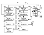
- FIG. 2 is a functional block diagram of an IMD including isolation circuitry.
- FIG. 3 is a timing diagram illustrating IMD function during a gradient field operating mode.
- FIG. 4 is a flow chart summarizing one method for controlling isolation circuitry included in an IMD.
- the invention is generally directed toward providing an IMD and an associated method for protecting a patient from unwanted tissue stimulation due to current induced on implanted leads in the presence of time-varying magnetic or electrical fields, such as during MRI procedures involving gradient magnetic fields or in the presence of time-varying electrical fields associated with electronic article surveillance systems (EAS).
- EAS electronic article surveillance systems
- gradient field refers to any time varying magnetic or electrical field that is strong enough to induce current on an implanted lead and potentially cause tissue stimulation.
- module refers to an application specific integrated circuit (ASIC), an electronic circuit, a processor (shared, dedicated, or group) and memory that execute one or more software or firmware programs, a combinational logic circuit, or other suitable components that provide the described functionality.
- ASIC application specific integrated circuit
- processor shared, dedicated, or group
- memory that execute one or more software or firmware programs, a combinational logic circuit, or other suitable components that provide the described functionality.
- FIG. 1 is a schematic diagram of an IMD coupled to a patient's heart via a cardiac lead.
- IMD 10 is shown as a single chamber cardiac device, however it is recognized that various embodiments of the present invention may be implemented in single, dual, or multi-chamber cardiac devices or single or multi-channel neurostimulators.
- Embodiments of the present invention include IMDs provided as monitoring devices without therapy delivery capabilities.
- IMDs provided with therapy delivery capabilities may include, for example, cardiac pacemakers, cardioverter/defibrillators, drug delivery devices, and neurostimulators.
- IMD 10 is embodied as an implantable cardioverter defibrillator (ICD) and is coupled to lead 30 for sensing cardiac signals and delivering electrical stimulation pulses to the heart in the form of cardiac pacing pulses and cardioversion/defibrillation shock pulses.
- Lead 30 is provided with a tip electrode 42 and ring electrode 44 which are generally used together for bipolar sensing and/or pacing functions or in combination with IMD housing 12 for unipolar sensing and/or pacing functions.
- Lead 30 also includes a right ventricular coil electrode 46 and a superior vena cava coil electrode 48 used in delivering high-voltage cardioversion and defibrillation shocks.
- Each of the electrodes 42 , 44 , 46 and 48 are coupled to individual connectors 34 , 36 , 38 and 40 included in a proximal lead connector assembly 32 via conductors extending through elongated lead body 31 .
- the lead connector assembly 32 is adapted for insertion into a connector bore provided in connector header 14 of IMD 10 .
- Electrode terminals 50 , 52 , 54 and 56 included in connector header 14 are electrically coupled to lead connectors 34 , 36 , 38 and 40 when lead connector assembly 32 is fully inserted in the connector header bore.
- Electrode terminals 50 , 52 , 54 and 56 are electrically coupled to internal IMD circuitry 16 , enclosed in hermetically sealed IMD housing 12 . Electrode terminals 50 , 52 , 54 and 56 are coupled to internal circuitry 16 via isolation circuitry 60 and protection circuitry 18 , shown schematically in FIG. 1 .
- the actual physical location of isolation circuitry 60 and protection circuitry 18 may be anywhere between electrode terminals 50 , 52 , 54 , and 56 and any portion of the internal circuitry 16 .
- the functionality of isolation circuitry 60 may be implemented using dedicated components or providing dual functionality of existing switching devices included in IMD 10 .
- Isolation circuitry 60 provides protection to the patient against unwanted tissue stimulation due to current induced on conductors carried by lead body 31 .
- current induced on lead conductors can be carried along a circuit path that includes lead 30 , the IMD housing 12 , and body tissue.
- Isolation circuitry 60 interrupts this circuit path by introducing a high-impedance element as will be described in greater detail herein.
- Protection circuitry 18 is generally grounded to IMD housing 12 thereby providing a path from electrode terminals 50 , 52 , 54 , and 56 to the IMD housing 12 , completing the circuit pathway through the patient's body along which induced currents may be conducted.
- Isolation circuitry 60 is provided to open that circuit pathway to prevent unwanted tissue stimulation in an MRI or other gradient field environment.
- Protection circuitry 18 is provided for eliminating or minimizing electromagnetic interference (EMI) that may be encountered in normal operating environments.
- EMI can produce a potential between any of electrodes 42 , 44 , 46 and 48 and housing 12 . Circuit elements and parasitic effects provide paths for current to flow as a result of these potentials.
- Protection circuitry 18 prevents EMI from being coupled to the internal circuitry 16 , which may otherwise cause inappropriate IMD function.
- Protection circuitry 18 typically includes electrically insulated, filtered feedthroughs such that electrical connections made between electrode terminals 50 , 52 , 54 , and 56 and internal circuitry 16 are electrically isolated from IMD housing 12 .
- the filtered feedthroughs typically include capacitive elements for filtering EMI. Examples of protection circuitry included in IMDs are generally disclosed in U.S. Pat. No.
- Protection circuitry 18 may include other noise-reduction and protection networks for static discharge and other transient voltages that may arise due to EMI.
- FIG. 2 is a functional block diagram of an IMD including isolation circuitry.
- IMD 10 generally includes timing and control circuitry 152 and an operating system that may employ microprocessor 154 or a digital state machine for timing sensing and therapy delivery functions in accordance with a programmed operating mode.
- Microprocessor 154 and associated memory 156 are coupled to the various components of IMD 10 via a data/address bus 155 .
- IMD 10 includes therapy delivery unit 150 for delivering an electrical stimulation therapy, such as cardiac pacing therapies, under the control of timing and control 152 .
- Therapy delivery unit 150 is typically coupled to two or more electrode terminals 168 via switch/multiplexer 158 .
- Switch/MUX 158 is used for selecting which electrodes and corresponding polarities are used for delivering electrical stimulation pulses.
- Electrode terminals 168 may also be used for receiving electrical signals from the body, such as cardiac signals or other electromyogram (EGM) signals, or for measuring impedance. In the case of cardiac stimulation devices, cardiac electrical signals are sensed for determining when an electrical stimulation therapy is needed and in controlling the timing of stimulation pulses.
- EMG electromyogram
- Electrode terminals 168 are typically included in a connector header as described in conjunction with FIG. 1 . Electrode terminals 168 may be electrically coupled to switch/MUX 158 via the isolation circuit 180 and any EMI protection circuitry 182 . The remaining functional blocks shown in FIG. 2 are typically implemented on a hybrid circuit board having contact pads for making electrical connections to protection circuitry 182 . Isolation circuitry 180 may be implemented anywhere between electrode terminals 168 and the connections to the various components included on a hybrid circuit board.
- Isolation circuitry 180 may include switching elements physically located at separate locations relative to the hybrid circuit board and IMD housing. If isolation of an associated lead from all IMD circuitry is desired, isolation circuitry 180 could be located outside the IMD housing or contained within a separate Faraday shield within the IMD housing. In other embodiments, isolation circuitry 180 may include switches used to isolate only portions of the hybrid circuitry from an associated lead and might include switching elements incorporated on the hybrid circuit board.
- IMD 10 may be provided with switches used for protecting IMD circuitry from voltages produced by external defibrillation.
- Switches 185 a through 185 d may include such switches.
- any of switches 185 a through 185 d serving functionally as a part of isolation circuit 180 for protecting the patient from induced current in the presence of time-varying EM fields may be embodied as a switch already provided in IMD 10 for protecting the IMD circuitry from voltages produced by external defibrillation.
- Electrodes used for sensing and electrodes used for stimulation may be selected via switch matrix 158 .
- electrode terminals 168 are coupled to signal processing circuitry 160 via switch matrix 158 .
- Signal processor 160 includes sense amplifiers and may include other signal conditioning circuitry and an analog to digital converter. Electrical signals may then be used by microprocessor 154 for detecting physiological events, such as detecting and discriminating cardiac arrhythmias.
- microprocessor 154 uses signals received at electrode terminals 168 for automatically detecting induced signals associated with a gradient field, such as a time-varying magnetic field associated with MRI.
- a gradient field sensor circuit 186 may be provided for sensing external signals corresponding to a time-varying MRI or other gradient field environment.
- Gradient field sensor circuit 186 may be embodied according to the sensor circuit generally disclosed in U.S. Pat. No. 6,198,972 (Hartlaub et al.), hereby incorporated herein by reference in its entirety.
- Gradient field sensor circuit 186 may be located anywhere in a patient's body and may therefore alternatively be coupled to IMD circuitry via a sensor terminal 170 .
- microprocessor 154 In response to a gradient field detection signal generated by gradient field sensor circuit 186 , microprocessor 154 causes timing and control circuitry 152 to generate a signal on signal line 184 that opens switches 185 a through 185 d included in isolation circuitry 180 .
- the circuit path through the IMD housing and the patient's body is effectively opened thereby preventing unwanted tissue stimulation due to induced currents on implanted leads coupled to IMD 10 .
- a sensor that detects the very strong static magnetic field may be used alone or in conjunction with other sensors to activate isolation circuitry 180
- IMD 10 may additionally or alternatively be coupled to one or more physiological sensors.
- physiological sensor terminals 170 are provided and are electrically coupled to a sensor interface 160 via protection circuitry 182 .
- Sensor terminals 170 may also be electrically coupled to IMD circuitry, or portions of IMD circuitry, through isolation circuitry 180 when terminals 170 are coupled to elongated leads that could carry induced currents to body tissue.
- Physiological sensors may include pressure sensors, accelerometers, flow sensors, blood chemistry sensors, activity sensors or other physiological sensors known for use with IMDs.
- Signals received at sensor terminals 170 are received by a sensor interface 162 which provides sensor signals to signal processing circuitry 160 .
- Sensor signals are used by microprocessor 154 for detecting physiological events or conditions.
- IMD 10 may monitor heart wall motion, blood pressure, blood chemistry, respiration, or patient activity. Monitored signals may be used for sensing the need for delivering a therapy under control of the operating system.
- the operating system includes associated memory 156 for storing a variety of programmed-in operating mode and parameter values that are used by microprocessor 154 .
- the memory 156 may also be used for storing data compiled from sensed physiological signals and/or relating to device operating history for telemetry out on receipt of a retrieval or interrogation instruction. All of these functions and operations are known in the art, and many are generally employed to store operating commands and data for controlling device operation and for later retrieval to diagnose device function or patient condition.
- IMD 10 further includes telemetry circuitry 164 and antenna 128 .
- Programming commands or data are transmitted during uplink or downlink telemetry between IMD telemetry circuitry 164 and external telemetry circuitry included in a programmer or monitoring unit.
- Telemetry circuitry 164 and antenna 128 may correspond to telemetry systems known in the art.
- a gradient field mode command is transmitted to IMD telemetry circuitry 164 by a clinician or other user using an external programmer.
- microprocessor 154 causes timing and control circuitry 152 to generate a signal on signal line 184 to open switches included in isolation circuitry 180 .
- Isolation circuitry 180 generally includes switches 185 a through 185 d which may be embodied as electro-mechanical relays, semiconductor devices, or MEMS relays. Switches 185 included in isolation circuitry 180 may be implemented as generally described in the above-incorporated Hartlaub patent. It is recognized that each of switches 185 a through 185 d may include one or more electronic switches coupled in series to form a high-impedance element through isolation circuitry 180 .
- the number of switches 185 included in isolation circuitry 180 will vary between applications and will correspond to the number of electrode terminals 168 and sensor terminals 170 that need to be electrically disconnected from the IMD ground path to prevent conduction of currents induced on elongated lead conductors during MRI procedures or in the presence of other gradient EM fields.
- timing and control circuitry 152 When microprocessor 156 determines that an electrical stimulation therapy is needed, or if an electrical stimulation therapy is in process upon initiation of the gradient field operating mode, timing and control circuitry 152 generates a transient “close” signal on signal line 184 .
- the “close” signal is generated just prior to or contemporaneously with the generation of an electrical stimulation pulse by therapy delivery unit 150 .
- a stimulation pulse generated by therapy delivery unit 150 is delivered to electrode terminals 168 across isolation circuitry 180 .
- the “close” signal causes at least one switch included in isolation circuitry 180 that corresponds to a selected stimulation electrode to briefly close so that the stimulation pulse can be delivered. Other switches included in isolation circuitry 180 may remain open during stimulation pulse delivery.
- signal line 184 may carry a multiplexed signal for operating multiple switches included in isolation circuitry 180 individually.
- a switch coupled to electrode terminal 56 corresponding to tip electrode 42 may be controlled separately from a switch coupled to electrode terminal 54 , corresponding to ring electrode 44 to allow unipolar stimulation using tip electrode 42 during a gradient field operating mode.
- IMD 10 may optionally be equipped with patient alarm circuitry 166 for generating audible tones, a perceptible vibration, muscle stimulation or other sensory stimulation for notifying the patient that a patient alert condition has been detected by IMD 10 .
- an alarm signal may be generated upon detection of a gradient field or upon initiating a gradient field mode of operation.
- FIG. 3 is a timing diagram illustrating IMD function during a gradient field operating mode.
- a gradient field mode is initiated in response to a gradient field operating mode command or the automatic detection of gradient field signals, corresponding to a time-varying MRI field or other gradient EM field, by a gradient field sensor circuit.
- Two biasing signals 205 and 215 are provided to individual switches, for example MOSFETs, included in isolation circuitry.
- the MOSFET switches are biased with high signals 208 and 214 that maintain the switches in a closed or ON operative state.
- a MOSFET may be biased to 5.0 volts relative to circuit common to hold the transistor in the ON state to allow normal sensing and therapy delivery functions.
- biasing signals 205 and 215 are switched to low signals 210 and 216 to open the corresponding MOSFETs to an OFF operative state.
- the MOSFETs may be biased to 0.0 volts relative to circuit common to hold the transistor in the OFF state to prevent conduction of induced currents to excitable body tissue.
- a feedback or bootstrap network could be used to maintain the correct state of the MOSFET.
- Pacing pulses 206 a , 206 b , 206 c through 206 n are delivered after the initiation of gradient field mode at time 202 .
- Pacing therapy may have been in progress at the time of initiating the gradient field mode or a need for pacing therapy may be detected during the gradient field mode using other sensors or circuits that are not opened by isolation circuitry.
- initiation of the gradient field mode may include maintaining a predetermined pacing rate.
- Intrinsic cardiac signals may be sensed during the gradient field operating mode through high impedance signal path sensing channels or utilize a gradient energy cancellation sensing method.
- At least one switch (for unipolar pacing) included in isolation circuitry is transiently closed by generating a high biasing signal 212 a , 212 b , 212 c , 212 n at appropriate times relative to pacing pulses 206 a through 206 n .
- two switches may be transiently closed during pacing pulse delivery.
- Timing and control module 152 FIG. 2 ) controls the alternation between high and low bias signal levels applied to isolation circuit switches to control the operative state of the switches.
- a switch is closed to close a pacing or electrical stimulation circuit at appropriate times during the gradient field mode to allow therapeutic stimulation to be performed, for example during MRI procedures.
- the switch(es) included in a pacing or electrical stimulation circuit are briefly closed for an interval of time starting just prior to or approximately the same time as a stimulation pulse and extending for a time at least equal to the stimulation pulse width. While the timing diagram shown in FIG. 3 illustrates the delivery of cardiac pacing pulses, it is recognized that any type of electrical stimulation pulses may be delivered during a gradient field mode by controlling the opening and closing of switches included in isolation circuitry. For example the need for high-voltage cardioversion/defibrillation shocks may be detected based on sensing intrinsic signals using a gradient energy cancellation method and high energy therapies may be delivered based on determining a reliable sensing signal for arrhythmia detection.
- FIG. 4 is a flow chart summarizing one method for controlling isolation circuitry included in an IMD.
- Flow chart 300 is intended to illustrate the functional operation of the device, and should not be construed as reflective of a specific form of software or hardware necessary to practice the invention. It is believed that the particular form of software will be determined primarily by the particular system architecture employed in the device and by the particular detection and therapy delivery methodologies employed by the device. Providing software and/or hardware to accomplish the present invention in the context of any modern IMD, given the disclosure herein, is within the abilities of one of skill in the art.
- the IMD microprocessor initiates a gradient field operating mode at block 306 .
- the gradient field operating mode is initiated in response to receipt of an external command provided to the IMD using a programmer or other device enabled for telemetric communication with the IMD (block 304 ).
- the gradient field operating mode is alternatively initiated in response to the detection of external or internal high level signals corresponding to an MRI or other time-varying EM environment by gradient field sensor circuit at block 302 .
- switches included in isolation circuitry are opened at block 310 .
- a gradient magnetic field may induce currents on implanted lead conductors large enough to cause tissue stimulation. Opening of isolation circuitry switches opens the circuit path through the capacitive feedthrough elements and the IMD housing and patient's body, preventing conduction of induced currents and unwanted tissue stimulation.
- timing and control module 152 determines if a therapeutic stimulation pulse is needed based on programmed therapy delivery mode. Upon triggering the generation of a therapy stimulation pulse, timing and control 152 generates a signal to transiently close one or more isolation circuitry switches included in a stimulation circuit path in order to allow stimulation pulse delivery at block 318 .
- the IMD microprocessor monitors for receipt of an external command indicating that a normal operating mode should be restored at decision block 322 . Additionally or alternatively, the IMD microprocessor automatically monitors for an end to the detection of gradient signals by a gradient field sensor.
- the gradient field mode may be maintained for a fixed interval of time after gradient field mode initiation. For example, the gradient field mode may be maintained for 30 minutes, one hour, or another interval of time that is expected to extend safely beyond the completion of an MRI procedure. As long as the gradient field mode is maintained, timing and control module 152 continues to control transient closure of stimulation circuit path switches included in isolation circuitry contemporaneously with the generation of therapeutic stimulation pulses at block 318 .
- isolation circuitry switches are closed at block 326 . Closure of isolation switches restores normally closed sensing and stimulation circuit paths for normal IMD operation. The gradient field operation mode is then terminated at block 330 .
Abstract
Description
Claims (20)
Priority Applications (3)
| Application Number | Priority Date | Filing Date | Title |
|---|---|---|---|
| US11/380,241 US7729770B2 (en) | 2006-04-26 | 2006-04-26 | Isolation circuitry and method for gradient field safety in an implantable medical device |
| PCT/US2007/067254 WO2007127705A1 (en) | 2006-04-26 | 2007-04-24 | Isolation circuitry and method for gradient field safety in an implantable medical device |
| US12/759,228 US8050763B2 (en) | 2006-04-26 | 2010-04-13 | Isolation circuitry and method for gradient field safety in an implantable medical device |
Applications Claiming Priority (1)
| Application Number | Priority Date | Filing Date | Title |
|---|---|---|---|
| US11/380,241 US7729770B2 (en) | 2006-04-26 | 2006-04-26 | Isolation circuitry and method for gradient field safety in an implantable medical device |
Related Child Applications (1)
| Application Number | Title | Priority Date | Filing Date |
|---|---|---|---|
| US12/759,228 Continuation US8050763B2 (en) | 2006-04-26 | 2010-04-13 | Isolation circuitry and method for gradient field safety in an implantable medical device |
Publications (2)
| Publication Number | Publication Date |
|---|---|
| US20070255332A1 US20070255332A1 (en) | 2007-11-01 |
| US7729770B2 true US7729770B2 (en) | 2010-06-01 |
Family
ID=38370357
Family Applications (2)
| Application Number | Title | Priority Date | Filing Date |
|---|---|---|---|
| US11/380,241 Expired - Fee Related US7729770B2 (en) | 2006-04-26 | 2006-04-26 | Isolation circuitry and method for gradient field safety in an implantable medical device |
| US12/759,228 Expired - Fee Related US8050763B2 (en) | 2006-04-26 | 2010-04-13 | Isolation circuitry and method for gradient field safety in an implantable medical device |
Family Applications After (1)
| Application Number | Title | Priority Date | Filing Date |
|---|---|---|---|
| US12/759,228 Expired - Fee Related US8050763B2 (en) | 2006-04-26 | 2010-04-13 | Isolation circuitry and method for gradient field safety in an implantable medical device |
Country Status (2)
| Country | Link |
|---|---|
| US (2) | US7729770B2 (en) |
| WO (1) | WO2007127705A1 (en) |
Cited By (31)
| Publication number | Priority date | Publication date | Assignee | Title |
|---|---|---|---|---|
| US20080071168A1 (en) * | 2006-07-26 | 2008-03-20 | Karl Gauglitz | Systems and methods for sensing external magnetic fields in implantable medical devices |
| US20090234405A1 (en) * | 2008-03-12 | 2009-09-17 | Medtronic, Inc. | System and method for cardiac lead switching |
| US20090259265A1 (en) * | 2002-02-28 | 2009-10-15 | Greatbatch Ltd. | Electronic network components utilizing biocompatible conductive adhesives for direct body fluid exposure |
| US20100106227A1 (en) * | 2008-10-23 | 2010-04-29 | Pacesetter, Inc. | Systems and Methods for Disconnecting Electrodes of Leads of Implantable Medical Devices During an MRI to Reduce Lead Heating |
| US20100106214A1 (en) * | 2008-10-23 | 2010-04-29 | Pacesetter, Inc. | Systems and Methods for Exploiting the Tip or Ring Conductor of an Implantable Medical Device Lead During an MRI to Reduce Lead Heating and the Risks of MRI-Induced Stimulation |
| US20110015713A1 (en) * | 2008-10-23 | 2011-01-20 | Pacesetter, Inc. | Systems and methods for reducing lead heating and the risks of mri-induced stimulation |
| US20110152972A1 (en) * | 2009-12-22 | 2011-06-23 | Biotronik Crm Patent Ag | Switched protective device against electromagnetic interference |
| US8200334B1 (en) * | 2007-11-09 | 2012-06-12 | Pacesetter, Inc. | Systems and methods for remote monitoring of signals sensed by an implantable medical device during an MRI |
| US20120265263A1 (en) * | 2006-03-30 | 2012-10-18 | Medtronic, Inc. | Medical Device Sensing and Detection During MRI |
| US20130253297A1 (en) * | 2001-04-13 | 2013-09-26 | Greatbatch Ltd. | Switched diverter circuits for minimizing heating of an implanted lead and/or providing emi protection in a high power electromagnetic field environment |
| US8897887B2 (en) | 2006-06-08 | 2014-11-25 | Greatbatch Ltd. | Band stop filter employing a capacitor and an inductor tank circuit to enhance MRI compatibility of active medical devices |
| US9037258B2 (en) * | 2008-12-17 | 2015-05-19 | Greatbatch Ltd. | Switched safety protection circuit for an AIMD system during exposure to high power electromagnetic fields |
| US9108066B2 (en) | 2008-03-20 | 2015-08-18 | Greatbatch Ltd. | Low impedance oxide resistant grounded capacitor for an AIMD |
| US9248283B2 (en) | 2001-04-13 | 2016-02-02 | Greatbatch Ltd. | Band stop filter comprising an inductive component disposed in a lead wire in series with an electrode |
| US9295828B2 (en) | 2001-04-13 | 2016-03-29 | Greatbatch Ltd. | Self-resonant inductor wound portion of an implantable lead for enhanced MRI compatibility of active implantable medical devices |
| US9427596B2 (en) | 2013-01-16 | 2016-08-30 | Greatbatch Ltd. | Low impedance oxide resistant grounded capacitor for an AIMD |
| US9433782B2 (en) | 2012-12-04 | 2016-09-06 | Boston Scientific Neuromodulation Corporation | Implantable medical device having electromagnetic interference filter device to reduce pocket tissue heating |
| US9724520B2 (en) | 2014-01-30 | 2017-08-08 | Medtronic, Inc. | Methods, implantable medical devices, and systems to continue implementing a special mode of operation after experiencing a device reset |
| USRE46699E1 (en) | 2013-01-16 | 2018-02-06 | Greatbatch Ltd. | Low impedance oxide resistant grounded capacitor for an AIMD |
| US9931514B2 (en) | 2013-06-30 | 2018-04-03 | Greatbatch Ltd. | Low impedance oxide resistant grounded capacitor for an AIMD |
| US10080889B2 (en) | 2009-03-19 | 2018-09-25 | Greatbatch Ltd. | Low inductance and low resistance hermetically sealed filtered feedthrough for an AIMD |
| US10350421B2 (en) | 2013-06-30 | 2019-07-16 | Greatbatch Ltd. | Metallurgically bonded gold pocket pad for grounding an EMI filter to a hermetic terminal for an active implantable medical device |
| US10559409B2 (en) | 2017-01-06 | 2020-02-11 | Greatbatch Ltd. | Process for manufacturing a leadless feedthrough for an active implantable medical device |
| US10561837B2 (en) | 2011-03-01 | 2020-02-18 | Greatbatch Ltd. | Low equivalent series resistance RF filter for an active implantable medical device utilizing a ceramic reinforced metal composite filled via |
| US10589107B2 (en) | 2016-11-08 | 2020-03-17 | Greatbatch Ltd. | Circuit board mounted filtered feedthrough assembly having a composite conductive lead for an AIMD |
| US10905888B2 (en) | 2018-03-22 | 2021-02-02 | Greatbatch Ltd. | Electrical connection for an AIMD EMI filter utilizing an anisotropic conductive layer |
| US10912945B2 (en) | 2018-03-22 | 2021-02-09 | Greatbatch Ltd. | Hermetic terminal for an active implantable medical device having a feedthrough capacitor partially overhanging a ferrule for high effective capacitance area |
| US10953234B2 (en) | 2015-08-26 | 2021-03-23 | Element Science, Inc. | Wearable devices |
| US11185709B2 (en) | 2014-02-24 | 2021-11-30 | Element Science, Inc. | External defibrillator |
| US11198014B2 (en) | 2011-03-01 | 2021-12-14 | Greatbatch Ltd. | Hermetically sealed filtered feedthrough assembly having a capacitor with an oxide resistant electrical connection to an active implantable medical device housing |
| US11253715B2 (en) | 2018-10-10 | 2022-02-22 | Element Science, Inc. | Wearable medical device with disposable and reusable components |
Families Citing this family (38)
| Publication number | Priority date | Publication date | Assignee | Title |
|---|---|---|---|---|
| US20090163980A1 (en) * | 2007-12-21 | 2009-06-25 | Greatbatch Ltd. | Switch for turning off therapy delivery of an active implantable medical device during mri scans |
| US8989870B2 (en) | 2001-04-13 | 2015-03-24 | Greatbatch Ltd. | Tuned energy balanced system for minimizing heating and/or to provide EMI protection of implanted leads in a high power electromagnetic field environment |
| US8509913B2 (en) | 2001-04-13 | 2013-08-13 | Greatbatch Ltd. | Switched diverter circuits for minimizing heating of an implanted lead and/or providing EMI protection in a high power electromagnetic field environment |
| US20090163981A1 (en) | 2007-12-21 | 2009-06-25 | Greatbatch Ltd. | Multiplexer for selection of an mri compatible band stop filter or switch placed in series with a particular therapy electrode of an active implantable medical device |
| US7071307B2 (en) * | 2001-05-04 | 2006-07-04 | Syngenta Participations Ag | Nucleic acids and proteins with thioredoxin reductase activity |
| US8014867B2 (en) | 2004-12-17 | 2011-09-06 | Cardiac Pacemakers, Inc. | MRI operation modes for implantable medical devices |
| US8903505B2 (en) | 2006-06-08 | 2014-12-02 | Greatbatch Ltd. | Implantable lead bandstop filter employing an inductive coil with parasitic capacitance to enhance MRI compatibility of active medical devices |
| US7962224B1 (en) * | 2007-02-05 | 2011-06-14 | Advanced Neuromodulation Systems, Inc. | Stimulation lead, stimulation system, and method for limiting MRI-induced current in a stimulation lead |
| US7693576B1 (en) * | 2007-04-11 | 2010-04-06 | Pacesetter, Inc. | Capacitor-integrated feedthrough assembly for an implantable medical device |
| US8160708B2 (en) * | 2007-04-11 | 2012-04-17 | Pacesetter, Inc. | Capacitor-integrated feedthrough assembly with improved grounding for an implantable medical device |
| US8373384B2 (en) * | 2007-04-11 | 2013-02-12 | Pacesetter, Inc. | Capacitor-integrated feedthrough assembly with improved grounding for an implantable medical device |
| US8032228B2 (en) * | 2007-12-06 | 2011-10-04 | Cardiac Pacemakers, Inc. | Method and apparatus for disconnecting the tip electrode during MRI |
| US8086321B2 (en) | 2007-12-06 | 2011-12-27 | Cardiac Pacemakers, Inc. | Selectively connecting the tip electrode during therapy for MRI shielding |
| US8311637B2 (en) * | 2008-02-11 | 2012-11-13 | Cardiac Pacemakers, Inc. | Magnetic core flux canceling of ferrites in MRI |
| US8160717B2 (en) * | 2008-02-19 | 2012-04-17 | Cardiac Pacemakers, Inc. | Model reference identification and cancellation of magnetically-induced voltages in a gradient magnetic field |
| US8364279B2 (en) | 2008-09-25 | 2013-01-29 | Boston Scientific Neuromodulation Corporation | Electrical stimulation leads having RF compatibility and methods of use and manufacture |
| US8571661B2 (en) | 2008-10-02 | 2013-10-29 | Cardiac Pacemakers, Inc. | Implantable medical device responsive to MRI induced capture threshold changes |
| US8498698B2 (en) * | 2008-10-31 | 2013-07-30 | Medtronic, Inc. | Isolation of sensing and stimulation circuitry |
| US8560060B2 (en) * | 2008-10-31 | 2013-10-15 | Medtronic, Inc. | Isolation of sensing and stimulation circuitry |
| EP2367596A1 (en) | 2008-10-31 | 2011-09-28 | Medtronic, Inc. | Shunt-current reduction housing for an implantable therapy system |
| US9192769B2 (en) * | 2008-10-31 | 2015-11-24 | Medtronic, Inc. | Shunt-current reduction techniques for an implantable therapy system |
| US8712540B2 (en) * | 2008-11-26 | 2014-04-29 | Medtronic, Inc. | Patient programmer with automated MRI compatibility verification for active implantable medical device |
| EP2198917B1 (en) | 2008-12-19 | 2016-03-30 | Ela Medical | Generator for an implantable pacemaker, comprising means for commuting in safety mode during MRI tests |
| WO2010096138A1 (en) | 2009-02-19 | 2010-08-26 | Cardiac Pacemakers, Inc. | Systems and methods for providing arrhythmia therapy in mri environments |
| US8099173B2 (en) * | 2009-02-26 | 2012-01-17 | Pacesetter, Inc. | Implantable medical lead circuitry and methods for reducing heating and/or induced current |
| EP2329860B1 (en) * | 2009-12-03 | 2015-09-02 | Biotronik CRM Patent AG | Connection housing and manufacture of same |
| US8565874B2 (en) | 2009-12-08 | 2013-10-22 | Cardiac Pacemakers, Inc. | Implantable medical device with automatic tachycardia detection and control in MRI environments |
| US8855784B2 (en) * | 2009-12-31 | 2014-10-07 | Cardiac Pacemakers, Inc. | Implantable medical device including controllably isolated housing |
| US9008788B2 (en) * | 2010-02-10 | 2015-04-14 | Medtronic, Inc. | Enablement and/or disablement of an exposure mode of an implantable medical device |
| US8437862B2 (en) | 2011-03-29 | 2013-05-07 | Medtronic, Inc. | Magnetic field detection using magnetohydrodynamic effect |
| US8467882B2 (en) | 2011-03-29 | 2013-06-18 | Medtronic, Inc. | Magnetic field detection using magnetohydrodynamic effect |
| WO2012134603A1 (en) * | 2011-03-29 | 2012-10-04 | Medtronic, Inc. | Magnetic field detection using magnetohydrodynamic effect |
| EP2537553B1 (en) | 2011-06-21 | 2013-08-28 | Sorin CRM SAS | Probe for implantable cardiac prosthesis, comprising a built-in means for protection against the effects of MRI fields |
| EP2545958B1 (en) | 2011-07-12 | 2014-05-14 | Sorin CRM SAS | Probe for implantable cardiac prosthesis, comprising a means for protection against the thermal effects of MRI fields |
| EP2674193A1 (en) * | 2012-06-11 | 2013-12-18 | Sapiens Steering Brain Stimulation B.V. | Synchronization of the operation of an implantable medical device with the application of RF and/or gradient fields in an MRI system |
| US10286209B2 (en) * | 2016-04-29 | 2019-05-14 | Medtronic, Inc. | Methods and implantable medical devices for automatic entry to an exposure mode of operation upon exposure to a magnetic disturbance |
| WO2019023067A1 (en) * | 2017-07-25 | 2019-01-31 | Boston Scientific Neuromodulation Corporation | Systems and methods for making and using an enhanced connector of an electrical stimulation system |
| JP2023524630A (en) * | 2020-05-06 | 2023-06-13 | バイオトロニック エスエー アンド カンパニー カーゲー | A medical system that performs therapeutic functions on a patient |
Citations (18)
| Publication number | Priority date | Publication date | Assignee | Title |
|---|---|---|---|---|
| US4320763A (en) | 1979-10-10 | 1982-03-23 | Telectronics Pty. Limited | Protection device for pacemaker implantees |
| US4745923A (en) | 1985-11-20 | 1988-05-24 | Intermedics, Inc. | Protection apparatus for patient-implantable device |
| EP0773449A2 (en) * | 1995-11-09 | 1997-05-14 | Research Development Corporation Of Japan | Magnetic field sensor |
| US5649965A (en) | 1994-12-30 | 1997-07-22 | Ela Medical S.A. | Protection against electromagnetic perturbations of external origin for a active implantable device |
| US5759197A (en) | 1994-10-04 | 1998-06-02 | Medtronic, Inc. | Protective feedthrough |
| US6198972B1 (en) | 1997-04-30 | 2001-03-06 | Medtronic, Inc. | Control of externally induced current in implantable medical devices |
| US6414835B1 (en) | 2000-03-01 | 2002-07-02 | Medtronic, Inc. | Capacitive filtered feedthrough array for an implantable medical device |
| US20030036776A1 (en) | 2000-04-20 | 2003-02-20 | Foster Thomas H. | MRI-compatible implantable device |
| US6580947B1 (en) * | 2000-03-10 | 2003-06-17 | Medtronic, Inc. | Magnetic field sensor for an implantable medical device |
| US20030144705A1 (en) | 2002-01-29 | 2003-07-31 | Medtronic, Inc. | Methods and apparatus for controlling a pacing system in the presence of EMI |
| US20040088012A1 (en) * | 2002-10-30 | 2004-05-06 | Kroll Mark W. | Implantable stimulation device with isolating system for minimizing magnetic induction |
| US6804552B2 (en) * | 2000-11-03 | 2004-10-12 | Medtronic, Inc. | MEMs switching circuit and method for an implantable medical device |
| US20040267233A1 (en) | 2003-06-30 | 2004-12-30 | Codman Neuro Sciences Sarl | System and method for controlling an implantable medical device subject to magnetic field or radio frequency exposure |
| US20050070975A1 (en) * | 2003-09-30 | 2005-03-31 | Zeijlemaker Volkert A. | Controlling telemetry during magnetic resonance imaging |
| US6901292B2 (en) | 2001-03-19 | 2005-05-31 | Medtronic, Inc. | Control of externally induced current in an implantable pulse generator |
| US20060064149A1 (en) | 2004-09-23 | 2006-03-23 | Belacazar Hugo A | Implantable medical lead |
| US20070191914A1 (en) * | 2006-02-16 | 2007-08-16 | Stessman Nicholas J | Mri detector for implantable medical device |
| US20070255352A1 (en) * | 2006-04-27 | 2007-11-01 | Roline Glen M | Implantable sensors having current-based switches for improved fault tolerance |
Family Cites Families (2)
| Publication number | Priority date | Publication date | Assignee | Title |
|---|---|---|---|---|
| US5694965A (en) * | 1996-03-04 | 1997-12-09 | Maverick International, Inc. | Pneumatic pressure regulator |
| EP1776040A4 (en) * | 2004-08-09 | 2012-02-15 | Univ Johns Hopkins | Implantable mri compatible stimulation leads and antennas and related systems and methods |
-
2006
- 2006-04-26 US US11/380,241 patent/US7729770B2/en not_active Expired - Fee Related
-
2007
- 2007-04-24 WO PCT/US2007/067254 patent/WO2007127705A1/en active Application Filing
-
2010
- 2010-04-13 US US12/759,228 patent/US8050763B2/en not_active Expired - Fee Related
Patent Citations (18)
| Publication number | Priority date | Publication date | Assignee | Title |
|---|---|---|---|---|
| US4320763A (en) | 1979-10-10 | 1982-03-23 | Telectronics Pty. Limited | Protection device for pacemaker implantees |
| US4745923A (en) | 1985-11-20 | 1988-05-24 | Intermedics, Inc. | Protection apparatus for patient-implantable device |
| US5759197A (en) | 1994-10-04 | 1998-06-02 | Medtronic, Inc. | Protective feedthrough |
| US5649965A (en) | 1994-12-30 | 1997-07-22 | Ela Medical S.A. | Protection against electromagnetic perturbations of external origin for a active implantable device |
| EP0773449A2 (en) * | 1995-11-09 | 1997-05-14 | Research Development Corporation Of Japan | Magnetic field sensor |
| US6198972B1 (en) | 1997-04-30 | 2001-03-06 | Medtronic, Inc. | Control of externally induced current in implantable medical devices |
| US6414835B1 (en) | 2000-03-01 | 2002-07-02 | Medtronic, Inc. | Capacitive filtered feedthrough array for an implantable medical device |
| US6580947B1 (en) * | 2000-03-10 | 2003-06-17 | Medtronic, Inc. | Magnetic field sensor for an implantable medical device |
| US20030036776A1 (en) | 2000-04-20 | 2003-02-20 | Foster Thomas H. | MRI-compatible implantable device |
| US6804552B2 (en) * | 2000-11-03 | 2004-10-12 | Medtronic, Inc. | MEMs switching circuit and method for an implantable medical device |
| US6901292B2 (en) | 2001-03-19 | 2005-05-31 | Medtronic, Inc. | Control of externally induced current in an implantable pulse generator |
| US20030144705A1 (en) | 2002-01-29 | 2003-07-31 | Medtronic, Inc. | Methods and apparatus for controlling a pacing system in the presence of EMI |
| US20040088012A1 (en) * | 2002-10-30 | 2004-05-06 | Kroll Mark W. | Implantable stimulation device with isolating system for minimizing magnetic induction |
| US20040267233A1 (en) | 2003-06-30 | 2004-12-30 | Codman Neuro Sciences Sarl | System and method for controlling an implantable medical device subject to magnetic field or radio frequency exposure |
| US20050070975A1 (en) * | 2003-09-30 | 2005-03-31 | Zeijlemaker Volkert A. | Controlling telemetry during magnetic resonance imaging |
| US20060064149A1 (en) | 2004-09-23 | 2006-03-23 | Belacazar Hugo A | Implantable medical lead |
| US20070191914A1 (en) * | 2006-02-16 | 2007-08-16 | Stessman Nicholas J | Mri detector for implantable medical device |
| US20070255352A1 (en) * | 2006-04-27 | 2007-11-01 | Roline Glen M | Implantable sensors having current-based switches for improved fault tolerance |
Cited By (50)
| Publication number | Priority date | Publication date | Assignee | Title |
|---|---|---|---|---|
| US8855785B1 (en) | 2001-04-13 | 2014-10-07 | Greatbatch Ltd. | Circuits for minimizing heating of an implanted lead and/or providing EMI protection in a high power electromagnetic field environment |
| US20130253297A1 (en) * | 2001-04-13 | 2013-09-26 | Greatbatch Ltd. | Switched diverter circuits for minimizing heating of an implanted lead and/or providing emi protection in a high power electromagnetic field environment |
| US9295828B2 (en) | 2001-04-13 | 2016-03-29 | Greatbatch Ltd. | Self-resonant inductor wound portion of an implantable lead for enhanced MRI compatibility of active implantable medical devices |
| US9248283B2 (en) | 2001-04-13 | 2016-02-02 | Greatbatch Ltd. | Band stop filter comprising an inductive component disposed in a lead wire in series with an electrode |
| US8751013B2 (en) * | 2001-04-13 | 2014-06-10 | Greatbatch Ltd. | Switched diverter circuits for minimizing heating of an implanted lead and/or providing EMI protection in a high power electromagnetic field environment |
| US8660645B2 (en) * | 2002-02-28 | 2014-02-25 | Greatbatch Ltd. | Electronic network components utilizing biocompatible conductive adhesives for direct body fluid exposure |
| US20090259265A1 (en) * | 2002-02-28 | 2009-10-15 | Greatbatch Ltd. | Electronic network components utilizing biocompatible conductive adhesives for direct body fluid exposure |
| US8818489B2 (en) * | 2006-03-30 | 2014-08-26 | Medtronic, Inc. | Medical device sensing and detection during MRI |
| US20120265263A1 (en) * | 2006-03-30 | 2012-10-18 | Medtronic, Inc. | Medical Device Sensing and Detection During MRI |
| US8897887B2 (en) | 2006-06-08 | 2014-11-25 | Greatbatch Ltd. | Band stop filter employing a capacitor and an inductor tank circuit to enhance MRI compatibility of active medical devices |
| US8049489B2 (en) * | 2006-07-26 | 2011-11-01 | Cardiac Pacemakers, Inc. | Systems and methods for sensing external magnetic fields in implantable medical devices |
| US20080071168A1 (en) * | 2006-07-26 | 2008-03-20 | Karl Gauglitz | Systems and methods for sensing external magnetic fields in implantable medical devices |
| US9766307B2 (en) | 2006-07-26 | 2017-09-19 | Cardiac Pacemakers, Inc. | Systems and methods for sensing external magnetic fields in implantable medical devices |
| US10921396B2 (en) | 2006-07-26 | 2021-02-16 | Cardiac Pacemakers, Inc. | Systems and methods for sensing external magnetic fields in implantable medical devices |
| US8710826B2 (en) | 2006-07-26 | 2014-04-29 | Cardiac Pacemakers, Inc. | Systems and methods for sensing external magnetic fields in implantable medical devices |
| US8200334B1 (en) * | 2007-11-09 | 2012-06-12 | Pacesetter, Inc. | Systems and methods for remote monitoring of signals sensed by an implantable medical device during an MRI |
| US8620446B2 (en) | 2007-11-09 | 2013-12-31 | Pacesetter, Inc. | Systems and methods for remote monitoring of signals sensed by an implantable medical device during an MRI |
| US8332045B2 (en) | 2008-03-12 | 2012-12-11 | Medtronic, Inc. | System and method for cardiac lead switching |
| US20090234405A1 (en) * | 2008-03-12 | 2009-09-17 | Medtronic, Inc. | System and method for cardiac lead switching |
| US9108066B2 (en) | 2008-03-20 | 2015-08-18 | Greatbatch Ltd. | Low impedance oxide resistant grounded capacitor for an AIMD |
| US20100106227A1 (en) * | 2008-10-23 | 2010-04-29 | Pacesetter, Inc. | Systems and Methods for Disconnecting Electrodes of Leads of Implantable Medical Devices During an MRI to Reduce Lead Heating |
| US8301249B2 (en) | 2008-10-23 | 2012-10-30 | Pacesetter, Inc. | Systems and methods for exploiting the tip or ring conductor of an implantable medical device lead during an MRI to reduce lead heating and the risks of MRI-induced stimulation |
| US20110015713A1 (en) * | 2008-10-23 | 2011-01-20 | Pacesetter, Inc. | Systems and methods for reducing lead heating and the risks of mri-induced stimulation |
| US20100106214A1 (en) * | 2008-10-23 | 2010-04-29 | Pacesetter, Inc. | Systems and Methods for Exploiting the Tip or Ring Conductor of an Implantable Medical Device Lead During an MRI to Reduce Lead Heating and the Risks of MRI-Induced Stimulation |
| US9037258B2 (en) * | 2008-12-17 | 2015-05-19 | Greatbatch Ltd. | Switched safety protection circuit for an AIMD system during exposure to high power electromagnetic fields |
| US10080889B2 (en) | 2009-03-19 | 2018-09-25 | Greatbatch Ltd. | Low inductance and low resistance hermetically sealed filtered feedthrough for an AIMD |
| US20110152972A1 (en) * | 2009-12-22 | 2011-06-23 | Biotronik Crm Patent Ag | Switched protective device against electromagnetic interference |
| US8423133B2 (en) * | 2009-12-22 | 2013-04-16 | Biotronik Crm Patent Ag | Switched protective device against electromagnetic interference |
| US11198014B2 (en) | 2011-03-01 | 2021-12-14 | Greatbatch Ltd. | Hermetically sealed filtered feedthrough assembly having a capacitor with an oxide resistant electrical connection to an active implantable medical device housing |
| US11071858B2 (en) | 2011-03-01 | 2021-07-27 | Greatbatch Ltd. | Hermetically sealed filtered feedthrough having platinum sealed directly to the insulator in a via hole |
| US10561837B2 (en) | 2011-03-01 | 2020-02-18 | Greatbatch Ltd. | Low equivalent series resistance RF filter for an active implantable medical device utilizing a ceramic reinforced metal composite filled via |
| US10596369B2 (en) | 2011-03-01 | 2020-03-24 | Greatbatch Ltd. | Low equivalent series resistance RF filter for an active implantable medical device |
| US10016593B2 (en) | 2012-12-04 | 2018-07-10 | Boston Scientific Neuromodulation Corporation | Implantable medical device having electromagnetic interference filter device to reduce pocket tissue heating |
| US9433782B2 (en) | 2012-12-04 | 2016-09-06 | Boston Scientific Neuromodulation Corporation | Implantable medical device having electromagnetic interference filter device to reduce pocket tissue heating |
| USRE46699E1 (en) | 2013-01-16 | 2018-02-06 | Greatbatch Ltd. | Low impedance oxide resistant grounded capacitor for an AIMD |
| US9427596B2 (en) | 2013-01-16 | 2016-08-30 | Greatbatch Ltd. | Low impedance oxide resistant grounded capacitor for an AIMD |
| US9931514B2 (en) | 2013-06-30 | 2018-04-03 | Greatbatch Ltd. | Low impedance oxide resistant grounded capacitor for an AIMD |
| US10350421B2 (en) | 2013-06-30 | 2019-07-16 | Greatbatch Ltd. | Metallurgically bonded gold pocket pad for grounding an EMI filter to a hermetic terminal for an active implantable medical device |
| US9724520B2 (en) | 2014-01-30 | 2017-08-08 | Medtronic, Inc. | Methods, implantable medical devices, and systems to continue implementing a special mode of operation after experiencing a device reset |
| US10653887B2 (en) | 2014-01-30 | 2020-05-19 | Medtronic, Inc. | Methods, implantable medical devices, and systems to continue implementing a special mode of operation after experiencing a device reset |
| US11413464B2 (en) | 2014-01-30 | 2022-08-16 | Medtronic, Inc. | Methods, implantable medical devices, and systems to continue implementing a special mode of operation after experiencing a device reset |
| US11185709B2 (en) | 2014-02-24 | 2021-11-30 | Element Science, Inc. | External defibrillator |
| US10953234B2 (en) | 2015-08-26 | 2021-03-23 | Element Science, Inc. | Wearable devices |
| US11701521B2 (en) | 2015-08-26 | 2023-07-18 | Element Science, Inc. | Wearable devices |
| US10589107B2 (en) | 2016-11-08 | 2020-03-17 | Greatbatch Ltd. | Circuit board mounted filtered feedthrough assembly having a composite conductive lead for an AIMD |
| US10559409B2 (en) | 2017-01-06 | 2020-02-11 | Greatbatch Ltd. | Process for manufacturing a leadless feedthrough for an active implantable medical device |
| US10912945B2 (en) | 2018-03-22 | 2021-02-09 | Greatbatch Ltd. | Hermetic terminal for an active implantable medical device having a feedthrough capacitor partially overhanging a ferrule for high effective capacitance area |
| US10905888B2 (en) | 2018-03-22 | 2021-02-02 | Greatbatch Ltd. | Electrical connection for an AIMD EMI filter utilizing an anisotropic conductive layer |
| US11712571B2 (en) | 2018-03-22 | 2023-08-01 | Greatbatch Ltd. | Electrical connection for a hermetic terminal for an active implantable medical device utilizing a ferrule pocket |
| US11253715B2 (en) | 2018-10-10 | 2022-02-22 | Element Science, Inc. | Wearable medical device with disposable and reusable components |
Also Published As
| Publication number | Publication date |
|---|---|
| US8050763B2 (en) | 2011-11-01 |
| US20100198309A1 (en) | 2010-08-05 |
| US20070255332A1 (en) | 2007-11-01 |
| WO2007127705A1 (en) | 2007-11-08 |
Similar Documents
| Publication | Publication Date | Title |
|---|---|---|
| US7729770B2 (en) | Isolation circuitry and method for gradient field safety in an implantable medical device | |
| EP0715866B1 (en) | Implantable cardiac stimulating device with periodic lead integrity testing | |
| US6580948B2 (en) | Interface devices for instruments in communication with implantable medical devices | |
| US8818489B2 (en) | Medical device sensing and detection during MRI | |
| EP1469907B1 (en) | Medical implantable system for reducing magnetic resonance effects | |
| US8583255B2 (en) | Implantable cardiac prosthesis generator having protection from an MRI examination | |
| JP2805214B2 (en) | Method and apparatus for reliably programming a pacemaker | |
| US7113827B2 (en) | Determining the presence and type of probe associated with an active implantable medical device, in particular a cardiac pacemaker | |
| CN103517733B (en) | There is pace-making during electromagnetic interference | |
| US7233825B2 (en) | Impedance measurement in implanted device | |
| US20110245888A1 (en) | Medical device with charge leakage detection | |
| US8554318B2 (en) | Detection of strong static magnetic fields and MRI examination safekeeping for an implantable cardiac prosthesis | |
| WO1996037258A1 (en) | Method and apparatus for automatic shock electrode enabling | |
| WO2012115723A1 (en) | Emergency mode switching for non-pacing modes | |
| US9302100B2 (en) | Lead monitoring frequency based on lead and patient characteristics | |
| US9409026B2 (en) | Lead monitoring frequency based on lead and patient characteristics | |
| US9399141B2 (en) | Lead monitoring frequency based on lead and patient characteristics | |
| WO1997043003A1 (en) | Implantable medical device with confirmation of patient activation | |
| WO2015123483A1 (en) | Lead monitoring frequency based on lead and patient characteristics |
Legal Events
| Date | Code | Title | Description |
|---|---|---|---|
| AS | Assignment |
Owner name: MEDTRONIC, INC., MINNESOTA Free format text: ASSIGNMENT OF ASSIGNORS INTEREST;ASSIGNORS:CABELKA, LONNY V.;MANAHAN, DAVID E.;PAPE, FORREST C.M.;AND OTHERS;REEL/FRAME:017529/0236;SIGNING DATES FROM 20060419 TO 20060424 Owner name: MEDTRONIC, INC.,MINNESOTA Free format text: ASSIGNMENT OF ASSIGNORS INTEREST;ASSIGNORS:CABELKA, LONNY V.;MANAHAN, DAVID E.;PAPE, FORREST C.M.;AND OTHERS;SIGNING DATES FROM 20060419 TO 20060424;REEL/FRAME:017529/0236 |
|
| FEPP | Fee payment procedure |
Free format text: PAYOR NUMBER ASSIGNED (ORIGINAL EVENT CODE: ASPN); ENTITY STATUS OF PATENT OWNER: LARGE ENTITY |
|
| FPAY | Fee payment |
Year of fee payment: 4 |
|
| FEPP | Fee payment procedure |
Free format text: MAINTENANCE FEE REMINDER MAILED (ORIGINAL EVENT CODE: REM.) |
|
| LAPS | Lapse for failure to pay maintenance fees |
Free format text: PATENT EXPIRED FOR FAILURE TO PAY MAINTENANCE FEES (ORIGINAL EVENT CODE: EXP.) |
|
| STCH | Information on status: patent discontinuation |
Free format text: PATENT EXPIRED DUE TO NONPAYMENT OF MAINTENANCE FEES UNDER 37 CFR 1.362 |
|
| FP | Lapsed due to failure to pay maintenance fee |
Effective date: 20180601 |