US7730202B1 - Dynamic interrupt timer - Google Patents
Dynamic interrupt timer Download PDFInfo
- Publication number
- US7730202B1 US7730202B1 US09/906,589 US90658901A US7730202B1 US 7730202 B1 US7730202 B1 US 7730202B1 US 90658901 A US90658901 A US 90658901A US 7730202 B1 US7730202 B1 US 7730202B1
- Authority
- US
- United States
- Prior art keywords
- timer
- network
- memory buffer
- timer activation
- activation period
- Prior art date
- Legal status (The legal status is an assumption and is not a legal conclusion. Google has not performed a legal analysis and makes no representation as to the accuracy of the status listed.)
- Expired - Fee Related, expires
Links
Images


Classifications
-
- H—ELECTRICITY
- H04—ELECTRIC COMMUNICATION TECHNIQUE
- H04L—TRANSMISSION OF DIGITAL INFORMATION, e.g. TELEGRAPHIC COMMUNICATION
- H04L47/00—Traffic control in data switching networks
- H04L47/10—Flow control; Congestion control
-
- H—ELECTRICITY
- H04—ELECTRIC COMMUNICATION TECHNIQUE
- H04L—TRANSMISSION OF DIGITAL INFORMATION, e.g. TELEGRAPHIC COMMUNICATION
- H04L47/00—Traffic control in data switching networks
- H04L47/10—Flow control; Congestion control
- H04L47/11—Identifying congestion
-
- H—ELECTRICITY
- H04—ELECTRIC COMMUNICATION TECHNIQUE
- H04L—TRANSMISSION OF DIGITAL INFORMATION, e.g. TELEGRAPHIC COMMUNICATION
- H04L47/00—Traffic control in data switching networks
- H04L47/10—Flow control; Congestion control
- H04L47/19—Flow control; Congestion control at layers above the network layer
- H04L47/193—Flow control; Congestion control at layers above the network layer at the transport layer, e.g. TCP related
-
- H—ELECTRICITY
- H04—ELECTRIC COMMUNICATION TECHNIQUE
- H04L—TRANSMISSION OF DIGITAL INFORMATION, e.g. TELEGRAPHIC COMMUNICATION
- H04L47/00—Traffic control in data switching networks
- H04L47/10—Flow control; Congestion control
- H04L47/28—Flow control; Congestion control in relation to timing considerations
- H04L47/283—Flow control; Congestion control in relation to timing considerations in response to processing delays, e.g. caused by jitter or round trip time [RTT]
Definitions
- This invention relates to timers in digital systems that have adjustable granularity, granularity which dynamically adjusts to communication conditions.
- TCP transmission control protocol
- a flow is a series of frames exchanged between two connection endpoints defined by a network address and a port number pair for each end of the connection.
- a flow is initiated by a request at one of the endpoints for content which is accessible through the other connection endpoint.
- the flow that is created in response to the request consist of packets containing the requested content and control messages exchanged between the two endpoints.
- Examples of exchanges of information include requests and transmission of data to and from client entities (client) and server entities (server).
- client is the requesting endpoint; however, the server at times also requests information from a client.
- Applications of digital systems include transactions on the Internet, where the client is an individual connecting to a host's site and the host's site is considered the server. The individual requests information from the host site. Information is then transmitted along the Internet from the host site to the individual.
- the individual and the host site exchange various information packets with one another. The individual browses the host's site for specific products and/or services. The host site responds with availability and price of the goods and services. The individual responds with an order, which can include credit card information and shipping information.
- Protocols allow efficient management of information and exchange over communication networks such as the Internet. Protocols are able to decide how to break up the transmission of information.
- a receiver e.g., server
- the receiver sends an acknowledge packet back to the sender (e.g., client). If the sender does not receive an acknowledge packet after an allotted amount of time, TCP requires that the sender retransmit the packet.
- Other features of TCP allow for flow control; a receiver allows the sender to send only as much information at a time that the receiver's data buffers can store.
- TCP and other communication protocols implement the use of timers. Timers are used to acknowledge control, and initiate and request (or re-initiate) transmission of information and information packets. Timers can also be implemented to control and monitor events. TCP includes, among other timers, an acknowledge timer, a round trip timer, a persist timer, and a keep alive timer. In TCP, timers can have a range of 200 milliseconds (ms) to several seconds.
- Granularity relates to the number of interrupts over a defined time period. An interrupt is when a timer activates. The fewer number of interrupts over the defined time period, the lesser the granularity. In other words, if a timer activates (interrupts) 10 times over the defined time period, the granularity is lesser than if the timer activates (interrupts) 20 times over the same defined time period.
- the retransmitted packets are packets containing information that has yet to be processed. Situations in which packets can be retransmitted are when an entity does not receive an acknowledge packet, the timer is started and after the set time the packet is retransmitted. Received packets that are yet to be processed, can be stored in memory buffers of devices; however, memory buffers are a limited resource that can be quickly filled during periods of peak network traffic. If memory buffers fill up, a retransmit can be requested, or transmission can be ceased.
- Traffic related to information flows over networks varies depending on various factors.
- a simplistic example of congestion takes place when numerous clients are attempting to access a particular server.
- Factors that affect information (data) flows include the current data stream bandwidth, the number of data flows (TCP flows), the number of requests for memory access, the current network traffic, network congestion, the time of day, the season of the year, or a combination of any of the factors.
- a method of adjusting a timer includes adjusting a timer activation period based on a characteristic of a network and setting the timer using the timer activation period.
- the timer is used in communicating information over the network.
- a timing unit for a network includes a timer and a timing control unit.
- the timing control unit is coupled to the timer, and is configured to adjust a timer activation period based on a characteristic of the network.
- the timing control unit is also configured to provide the timer activation period to the timer.
- FIG. 1 illustrates a transmission flow between a client and server.
- FIG. 2 illustrates a transmission flow between a client and server with a router intermediary.
- FIG. 3 is a flow chart illustrating detecting congestion and modifying timer granularity.
- FIG. 4 is a flow chart illustrating detecting various flows and modifying timer granularity.
- FIG. 5 is a block diagram illustrating a router.
- FIG. 6 is a block diagram illustrating a router with timer memories.
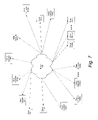
- FIG. 7 is a block diagram illustrating a network environment in which a system according to the present invention may be practiced.
- FIG. 8 depicts a block diagram of a computer system suitable for implementing the present invention, and example of one or more of client computers.
- FIG. 9 is a block diagram depicting a network in which a computer system is coupled to an internetwork, which is coupled, in turn, to client systems, as well as a server.
- FIG. 1 is a block diagram illustrating transmission between a client 100 and a server 110 .
- Client 100 transmits a synchronize (SYN) packet 102 to server 110 .
- Server 110 acknowledges packet 102 by transmitting a SYN-ACK packet 104 to client 100 .
- Client 100 responds to server 110 by transmitting an acknowledge (ACK) packet 106 .
- Information is transmitted in the form of packets DATA 1 108 and DATA 2 112 from client 100 to server 110 .
- Server 110 acknowledges receipt of this information by transmitting an ACK packet 114 .
- information such as DATA 3 116 can be transmitted to client 100 .
- Client 100 acknowledges receipt of DATA 3 116 by transmitting an ACK packet 118 .
- Client 100 terminates transmission flow made by client 100 by transmitting a FIN packet 120 to server 110 .
- a FIN-ACK packet 122 is sent to client 100 to acknowledge that server 110 recognizes that transmission is ended.
- Client 100 in turn transmits an ACK packet 124 to complete transmission.
- timers can be used to control when retransmission of packets is performed, if retransmission is required.
- Client 100 and server 110 can incorporate memory buffers to store packet information.
- FIG. 2 is a block diagram illustrating transmission between client 100 and server 110 , with the use of an intermediary device.
- a router 205 is illustrated as the intermediary device.
- Router 205 intercepts the flows from client 100 and generates a new flow between itself and server 110 . Therefore, two flows exist, with one flow between client 100 and router 205 , and a second flow between router 205 and server 110 .
- router 205 controls information that passes between client 100 and server 110 . Communication paths are established from router 205 , namely between client 100 and server 110 .
- congestion and constrained resources are greater at server 110 , at other times at client 100 , and at certain times resources are equally congested and constrained for both server 110 and client 100 .
- Client 100 , server 110 , and router 205 can make use of memory buffers to store packet information with the memory buffer storing excess data.
- client 100 When client 100 desires to transmit information, client 100 transmits a SYN 1 packet 202 to router 205 .
- Router 205 acknowledges receipt of SYN 1 packet 202 , by transmitting a SYN-ACK 1 packet 204 to client 100 .
- Client 100 sends an ACK 1 packet 206 to router 205 .
- Information from client 100 is transmitted to router 205 in the form of packets DATA 1 210 and DATA 2 216 .
- Router 205 establishes communication with server 110 by transmitting a SYN 1 ′ packet 208 .
- Server 110 replies to router 205 with a SYN-ACK 1 ′ packet 212 .
- Router 205 transmits an ACK 2 packet 214 to server 110 recognizing SYN-ACK 1 ′ packet 212 .
- Router 205 is then authorized to transmit packets DATA 1 ′ 218 and DATA 2 ′ 222 to server 110 .
- Server 110 has the ability to transmit information back to client 100 . This process is illustrated by server 110 sending a DATA 3 packet 226 to router 205 . Router 205 passes DATA 3 ′ packet 228 along to client 100 . Router 205 also sends an ACK 5 packet 230 back to server 110 , acknowledging receipt of DATA 3 packet 226 from server 110 . The client 100 transmits an ACK 6 232 packet to router 205 acknowledging receipt of DATA 3 ′ packet 228 from router 205 . ACK 3 packet 220 is sent from router 205 to recognize receipt of DATA 1 210 and DATA 2 216 packets. ACK 4 packet 224 is sent from server 110 to recognize receipt of DATA 1 ′ 218 and DATA 2 ′ 222 packets.
- client 100 wishes to terminate communication, and sends a FIN packet 234 to router 205 .
- Router 205 advises server 110 that client 100 desires to end communication by sending a FIN′ packet 236 to server 110 .
- Server 110 acknowledges FIN′ packet 236 by transmitting a FIN-ACK packet 240 to router 205 .
- Router 205 acknowledges FIN-ACK packet 240 by transmitting an ACK 7 packet 242 to server 110 .
- Router 205 sends a FIN-ACK′ packet 238 to client 100 .
- Client 100 in turn, acknowledges FIN-ACK′ packet 238 by transmitting an ACK 8 packet 244 back to router 205 .
- timer granularity is a predetermined and set value for each timer.
- timer granularity can be altered (e.g., decreased or increased).
- time between timer interrupts or timer activation can be decreased or increased.
- a decrease in granularity allows processors, specifically processors in transmitting and receiving devices, to limit the computing that the processors are requested to perform.
- granularity can be increased. In other words, a shorter period is seen for timer activation (i.e., interrupts).
- An increase in granularity allows transmission between devices to occur more rapidly.
- processors responsible for receiving and transmitting packets are able to keep up with processing during situations in which congestion exists or is anticipated.
- An example of events or situations in which congestion exists includes peak shopping seasons where a multitude of individuals are attempting to access shopping sites. Another situation is a busy time of day in which individuals are checking their stock portfolios at their respective Internet brokerage sites.
- An example of an expected event that can cause congestion is when equipment is being repaired or maintained, limiting the capabilities of the network. Decrease or increase changes in granularity can be based on several metrics, metrics that are actually seen in the communication network or are anticipated in the communication network.
- granularity is decreased in order to alleviate the tasks imposed on processors that are handling the communication transfers of transmitted and received information.
- granularity is increased to allow for quicker transmission of packets.
- FIG. 3 illustrates a flow chart of a process that determines congestion in a network.
- a device that contains a timer receives a flow of transmission packets. Packets can be placed in a memory buffer if processors cannot immediately handle the transmitted packet, and the process may wait a set amount of time, step 310 .
- a determination is made as to whether an option to receive flows is terminated, step 320 . If the option is terminated, the process ends. If flows continue to be received, a device (e.g., a receiving or a sending device) determines congestion in the network, step 340 . If congestion is seen, granularity is decreased, step 350 . If congestion is not seen, granularity is increased, step 330 .
- the process pauses for an amount of time, step 310 , and then continues until transmission of the received or transmitted packet is complete, step 320 .
- a counter can be associated with each timer.
- the counter is increased whenever congestion flow is experienced.
- An increase in the counter relates to a decrease in the granularity of the timer.
- the counter measures delay or lack of transmission (processing) of a packet.
- the counter sets optimal granularity conditions by experienced flow or congestion. Examples of congestion include network congestion (i.e., congestion with a client network, such as the Internet, and between a client and a router); server network congestion (i.e., between router and server, or both); processor congestion (i.e., processor has more tasks to perform than time to perform the tasks); and memory congestion (i.e., the memory bandwidth is close to fully utilized, and additional requests for data from the memory adversely affects performance).
- network congestion i.e., congestion with a client network, such as the Internet, and between a client and a router
- server network congestion i.e., between router and server, or both
- processor congestion i.e., processor has more tasks to perform than time to
- Each incremental counter increase decreases the granularity of the timer.
- an 8 bit binary counter can be used. For the first increase of the counter or the value of 00000001, granularity is decreased and the timer is set to activate every ten seconds. For the next counter increase or value of 00000010, granularity is changed so the timer activates every 20 seconds. The next counter increase or value of 00000011 decreases granularity and sets the timer activation to 30 seconds. The counter progressively increases as the delay of the packet transmission is experienced, the delay relating to network congestion. In this particular example, a maximum timer activation time is set to 160 seconds. With the 8 bit counter, only the first four bits need be used. The maximum value of 160 seconds is reached when the counter has the value of 00001111. Once the set maximum timer value (or minimum granularity) is reached, the granularity stays at the minimum value until congestion flow conditions favorably change.
- a master counter can be employed, which increments at a continuous rate. Normally, the rate at which the master counter is incremented does not change.
- the processor is interrupted and all of the timer values stored in memory are read. If any of them expire, the corresponding event is scheduled for that TCP flow. If congestion is detected, the interrupts can be generated every other time (i.e., every two times) the counter changes values. Likewise, if congestion continues or increases, the interrupts can be generated every fourth time the counter changes values. This can continue (i.e., every eighth time, every sixteenth time, and so on). This is referred to herein as decreasing granularity.
- a decrease in granularity goes from many interrupts spaced closely that may cause a small number of events per interrupt to be executed, to few interrupts spaced further apart that usually causes a larger number of events to be executed per interrupt.
- a change in granularity is based on powers of two.
- the least significant bit of the counter can be examined for changes. As congestion increases, the second least significant bit is examined for changes; as the congestion further increases, the third significant bit can be examined for changes, and so on.
- FIG. 4 is a flowchart illustrating a process of detecting various flows and modifying timer granularity.
- a particular device can receive up to 128K flows per second. After such number of flows is exceeded, the memory buffers become full, and no more flows can be received. To allow continued transmission, granularity can be adjusted depending on the number of flows. Values that affect data flows include current data stream bandwidth; number of TCP flows; number of arbiter requests for memory access; current network traffic; network congestion; time of day (peak traffic expected or actually experienced); estimated traffic (season of the year); and a combination of the above. A determination can be made on actual or anticipated number of flows or congestion. A factor in estimating congestion is estimating data stream bandwidth. Data stream bandwidth estimates are derived by factors including the number of flows; arbiter device requests; network congestion (historical values); current time of delay (anticipated peak); and estimated traffic (related to event or season).
- granularity change can correspond directly to a preset value for the number of flows encountered.
- the receiving device controls the granularity change and measures the flow; however, a sending device can address the task of detecting flow and modifying granularity.
- a wait is performed for a predetermined amount of time, step 410 .
- a determination is made as to whether the transmission is complete or if a memory buffer has accepted the transmission, step 420 . If transmission is complete, the process ends. If continued transmission is seen, the number of flows is compared to the value A, step 430 . If flows are not greater than A, the granularity remains the same, step 440 .
- a wait is performed for the predetermined set of time, step 410 , and a determination is made as to whether transmission is completed 420 . If flows are greater than A, a determination is made to see if the flows are greater than B, step 450 . If the flows are greater than A, but less than B, granularity is decreased by two, step 460 . A wait is performed for the predetermined set of time, step 410 , and a determination is made as to whether transmission is completed 420 . A determination is made as to whether the flows are greater than B, but less than C, step 470 . If flows are less than C, then granularity is decreased by four, step 480 .
- the value of C is an upper limit value; if flows are greater than C, then granularity is decreased by eight, step 490 .
- a wait is performed for the predetermined set of time, step 410 , and a determination is made as to whether transmission is completed 420 .
- Flow control can also be measured by high and low watermarks.
- the status of the watermark determines flow, is used to determine flow control, and in turn determines the granularity of the timer.
- Flows can be assigned a high watermark and a low watermark.
- the high watermark value indicates the upper limit related to the number of frames contained in the flow.
- granularity can be increased.
- granularity can be decreased.
- Memory buffers can also make use of the high and low watermark concept, and adjust the granularity of the respective timers accordingly.
- FIG. 5 is a block diagram illustrating a router.
- a router can include a memory 500 that is directly interfaced to a processor 505 .
- Processor 505 communicates to an internal bus 510 .
- Router bus communicates to a packet memory 515 .
- Packet memory can be used to store flows prior to processing by the processor 505 .
- An interface or interfaces 520 provides connection to an external network from the router. Interfaces 520 communicates to the other devices in the router by way of bus 510 .
- FIG. 6 is a block diagram illustrating a router with timer memories.
- Timer memories can have timers based on timer length, priority, content, and/or a combination of the three.
- the memories include a timer memory A 600 , a timer memory B 605 , and a timer memory C 610 .
- each of the memories are independently connected to bus 510 .
- Timers e.g., TCP timers
- Timer memory A 600 , timer memory B 605 , and/or timer memory C 610 can be accessed at a predetermined time interval (e.g., N ms, where N is a predetermined number) to verify each timer. If the timer has expired, the process related to the timer is executed by the digital system (e.g., communication network) and the associated timer event is removed from memory. If the timer has not expired, the timer remains in memory until a future verification is made to determine if the timer has expired.
- a predetermined time interval e.g., N ms, where N is a predetermined number
- timer memory A 600 As the system, processor 505 , timer memory A 600 , timer memory B 605 , or timer memory C 610 become congested, the memory containing the timer is verified (i.e., inspected) at twice the predetermined time interval (i.e., two times N ms).
- the increase in time interval slows down the protocol process (e.g., TCP) while allowing a congested router added time to operate on flows that the router currently is processing. Further additional processing times can be provided to allow the router to handle added flows.
- protocol process e.g., TCP
- Timer memory A 600 , timer memory B 605 , and timer memory C 610 can be sorted to provide for different priorities. In particular, as congestion increases, reading of the timer memories 600 , 605 , or 610 , memory (or memories) containing voice and/or video packets is not affected (i.e., the time interval remains at N ms). However, during the same time, memory that contains other content (e.g., email content) is accessed at twice the predetermined time interval (i.e., two times X ms). With additional congestion, the time intervals can be increased accordingly.
- voice content stored in a particular memory would continue to be accessed at the predetermined time interval (i.e., N ms); video content in a particular memory would be accessed at two times the predetermined time interval (i.e., two times N ms); and other content would be accessed at four times the predetermined time interval (i.e., four times N ms).
- the predetermined time interval i.e., N ms
- video content in a particular memory would be accessed at two times the predetermined time interval (i.e., two times N ms)
- other content would be accessed at four times the predetermined time interval (i.e., four times N ms).
- Determining content in a particular memory and setting priority can be based on any of the following: contents of the packet, Media Access Control (MAC) address, Internet Protocol (IP) address, the type of service, the class of service type, quality of service metric, service level agreement, or virtual local area network (VLAN) information. Any or all of the preceding data provides information on content type. Determining content based on the preceding data avoids the need to inspect the actual content of the flows or packets stored in memory.
- MAC Media Access Control
- IP Internet Protocol
- VLAN virtual local area network
- FIG. 7 is a block diagram illustrating a network environment in which a system according to the present invention may be practiced.
- network 700 such as a private wide area network (WAN) or the Internet, includes a number of networked servers 710 ( 1 )-(N) that are accessible by client computers 720 ( 1 )-(N).
- Communication between client computers 720 ( 1 )-(N) and servers 710 ( 1 )-(N) typically occurs over a publicly accessible network, such as a public switched telephone network (PSTN), a DSL connection, a cable modem connection or large bandwidth trunks (e.g., communications channels providing T 1 or 0 C 3 service).
- PSTN public switched telephone network
- DSL connection a DSL connection
- cable modem connection or large bandwidth trunks
- Client computers 720 ( 1 )-(N) access servers 710 ( 1 )-(N) through, for example, a service provider.
- a service provider This might be, for example, an Internet Service Provider (ISP) such as America On-LineTM, ProdigyTM, CompuServeTM or the like. Access is typically had by executing application specific software (e.g., network connection software and a browser) on the given one of client computers 720 ( 1 )-(N).
- ISP Internet Service Provider
- application specific software e.g., network connection software and a browser
- One or more of client computers 720 ( 1 )-(N) and/or one or more of servers 710 ( 1 )-(N) may be, for example, a computer system of any appropriate design, in general, including a mainframe, a mini-computer or a personal computer system.
- a computer system typically includes a system unit having a system processor and associated volatile and non-volatile memory, one or more display monitors and keyboards, one or more diskette drives, one or more fixed disk storage devices and one or more printers.
- These computer systems are typically information handling systems which are designed to provide computing power to one or more users, either locally or remotely.
- Such a computer system may also include one or a plurality of I/O devices (i.e., peripheral devices) which are coupled to the system processor and which perforin specialized functions.
- I/O devices include modems, sound and video devices and specialized communication devices.
- Mass storage devices such as hard disks, CD-ROM drives and magneto-optical drives may also be provided, either as an integrated or peripheral device.
- client computers 720 ( 1 )-(N) is shown in detail in FIG. 8 .
- FIG. 8 depicts a block diagram of a computer system 810 suitable for implementing the present invention, and example of one or more of client computers 720 ( 1 )-(N).
- Computer system 810 includes a bus 812 which interconnects major subsystems of computer system 810 such as a central processor 814 , a system memory 816 (typically RAM, but which may also include ROM, flash RAM, or the like), an input/output controller 818 , an external audio device such as a speaker system 820 via an audio output interface 822 , an external device such as a display screen 824 via display adapter 826 , serial ports 828 and 830 , a keyboard 832 (interfaced with a keyboard controller 833 ), a storage interface 834 , a floppy disk drive 836 operative to receive a floppy disk 838 , and a CD-ROM drive 840 operative to receive a CD-ROM 842 .
- a bus 812 which interconnects major subsystems of computer system 810
- mouse 846 or other point-and-click device, coupled to bus 812 via serial port 828
- modem 847 coupled to bus 812 via serial port 830
- network interface 848 coupled directly to bus 812 .
- Bus 812 allows data communication between central processor 814 and system memory 816 , which may include both read only memory (ROM) or flash memory (neither shown), and random access memory (RAM) (not shown), as previously noted.
- the RAM is generally the main memory into which the operating system and application programs are loaded and typically affords at least 64 megabytes of memory space.
- the ROM or flash memory may contain, among other code, the Basic Input-Output system (BIOS) which controls basic hardware operation such as the interaction with peripheral components.
- BIOS Basic Input-Output system
- Applications resident with computer system 810 are generally stored on and accessed via a computer readable medium, such as a hard disk drive (e.g., fixed disk 844 ), an optical drive (e.g., CD-ROM drive 840 ), floppy disk unit 836 or other storage medium. Additionally, applications may be in the form of electronic packets modulated in accordance with the application and data communication technology when accessed via network modem 847 or interface 848 .
- Storage interface 834 may connect to a standard computer readable medium for storage and/or retrieval of information, such as a fixed disk drive 844 .
- Fixed disk drive 844 may be a part of computer system 810 or may be separate and accessed through other interface systems.
- Many other devices can be connected such as a mouse 846 connected to bus 812 via serial port 828 , a modem 847 connected to bus 812 via serial port 830 and a network interface 848 connected directly to bus 812 .
- Modem 847 may provide a direct connection to a remote server via a telephone link or to the Internet via an internet service provider (ISP).
- ISP internet service provider
- Network interface 848 may provide a direct connection to a remote server via a direct network link to the Internet via a POP (point of presence).
- Network interface 848 may provide such connection using wireless techniques, including digital cellular telephone connection, Cellular Digital Packet Data (CDPD) connection, digital satellite data connection or the like.
- CDPD Cellular Digital Packet Data
- computer system 810 may be any kind of computing device, and so includes personal data assistants (PDAs), network appliance, X-window terminal or other such computing device.
- PDAs personal data assistants
- the operating system provided on computer system 810 may be MS-DOS®, MS-WINDOWS®, OS/2®, UNIX®, Linux®, Cisco IOS®, CATOS® or other known operating system.
- Computer system 810 also supports a number of Internet access tools, including, for example, an HTTP-compliant web browser having a JavaScript interpreter, such as Netscape Navigator® 8.0, Microsoft Explorer® 8.0 and the like.
- a packet may be directly transmitted from a first block to a second block, or a packet may be modified (e.g., amplified, attenuated, delayed, latched, buffered, inverted, filtered, encoded or otherwise modified) between the blocks.
- modified packets e.g., amplified, attenuated, delayed, latched, buffered, inverted, filtered, encoded or otherwise modified
- a packet input at a second block may be conceptualized as a second packet derived from a first packet output from a first block due to physical limitations of the circuitry involved (e.g., there will inevitably be some attenuation and delay). Therefore, as used herein, a second packet derived from a first packet includes the first packet or any modifications to the first packet, whether due to circuit limitations or due to passage through other circuit elements which do not change the informational and/or final functional aspect of the first packet.
- any two components herein combined to achieve a particular functionality can be seen as “associated with” each other such that the desired functionality is achieved, irrespective of architectures or intermediate components.
- any two components so associated can also be viewed as being “operably connected”, or “operably coupled”, to each other to achieve the desired functionality.
- FIG. 9 is a block diagram depicting a network 900 in which computer system 810 is coupled to an internetwork 910 , which is coupled, in turn, to client systems 920 and 930 , as well as a server 940 .
- Internetwork 910 e.g., the Internet
- client systems 920 and 930 are also capable of coupling client systems 920 and 930 , and server 940 to one another.
- modem 847 , network interface 848 or some other method can be used to provide connectivity from computer system 810 to internetwork 910 .
- Computer system 810 , client system 920 and client system 930 are able to access information on server 940 using, for example, a web browser (not shown).
- Such a web browser allows computer system 810 , as well as client systems 920 and 930 , to access data on server 940 representing the pages of a website hosted on server 940 .
- Protocols for exchanging data via the Internet are well known to those skilled in the art.
- FIG. 9 depicts the use of the Internet for exchanging data, the present invention is not limited to the Internet or any particular network-based environment.
- a browser running on computer system 810 employs a TCP/IP connection to pass a request to server 940 , which can run an HTTP “service” (e.g., under the WINDOWS® operating system) or a “daemon” (e.g., under the UNIX® operating system), for example.
- HTTP HyperText Transfer Protocol
- daemon e.g., under the UNIX® operating system
- Such a request can be processed, for example, by contacting an HTTP server employing a protocol that can be used to communicate between the HTTP server and the client computer.
- the HTTP server responds to the protocol, typically by sending a “web page” formatted as an HTML file.
- the browser interprets the HTML file and may form a visual representation of the same using local resources (e.g., fonts and colors).
Abstract
Description
Claims (48)
Priority Applications (1)
| Application Number | Priority Date | Filing Date | Title |
|---|---|---|---|
| US09/906,589 US7730202B1 (en) | 2001-07-16 | 2001-07-16 | Dynamic interrupt timer |
Applications Claiming Priority (1)
| Application Number | Priority Date | Filing Date | Title |
|---|---|---|---|
| US09/906,589 US7730202B1 (en) | 2001-07-16 | 2001-07-16 | Dynamic interrupt timer |
Publications (1)
| Publication Number | Publication Date |
|---|---|
| US7730202B1 true US7730202B1 (en) | 2010-06-01 |
Family
ID=42200312
Family Applications (1)
| Application Number | Title | Priority Date | Filing Date |
|---|---|---|---|
| US09/906,589 Expired - Fee Related US7730202B1 (en) | 2001-07-16 | 2001-07-16 | Dynamic interrupt timer |
Country Status (1)
| Country | Link |
|---|---|
| US (1) | US7730202B1 (en) |
Cited By (12)
| Publication number | Priority date | Publication date | Assignee | Title |
|---|---|---|---|---|
| US20100254411A1 (en) * | 2009-04-06 | 2010-10-07 | Avaya Inc. | Network synchronization over ip networks |
| US20100254499A1 (en) * | 2009-04-06 | 2010-10-07 | Avaya Inc. | Network synchronization over ip networks |
| US20110078313A1 (en) * | 2009-09-30 | 2011-03-31 | St-Ericsson Sa | Method and system for managing a connection in a connection oriented in-order delivery environment |
| US20110078255A1 (en) * | 2009-09-30 | 2011-03-31 | Andrei Radulescu | Method and system for managing a connection in a connection oriented in-order delivery environment |
| US20120120848A1 (en) * | 2010-11-11 | 2012-05-17 | International Business Machines Corporation | Configurable network socket retransmission timeout parameters |
| US8335857B1 (en) * | 2009-05-21 | 2012-12-18 | Sprint Communications Company L.P. | System and methods of data transmission to devices |
| US20140006667A1 (en) * | 2012-06-27 | 2014-01-02 | Broadcom Corporation | Adaptive hardware interrupt moderation |
| US20140181818A1 (en) * | 2011-09-07 | 2014-06-26 | Amazon Technologies, Inc. | Optimization of packet processing by delaying a processor from entering an idle state |
| US20140281653A1 (en) * | 2013-03-15 | 2014-09-18 | International Business Machines Corporation | Reestablishing synchronization in a memory system |
| US9318171B2 (en) | 2013-03-15 | 2016-04-19 | International Business Machines Corporation | Dual asynchronous and synchronous memory system |
| US9430418B2 (en) | 2013-03-15 | 2016-08-30 | International Business Machines Corporation | Synchronization and order detection in a memory system |
| TWI732411B (en) * | 2015-03-27 | 2021-07-01 | 美商無限傳感有限公司 | Laser designator pulse detectors, laser detection systems, and methods of identifying at least one target |
Citations (21)
| Publication number | Priority date | Publication date | Assignee | Title |
|---|---|---|---|---|
| US5359593A (en) | 1993-08-26 | 1994-10-25 | International Business Machines Corporation | Dynamic bandwidth estimation and adaptation for packet communications networks |
| US5613129A (en) * | 1994-05-02 | 1997-03-18 | Digital Equipment Corporation | Adaptive mechanism for efficient interrupt processing |
| US5784554A (en) | 1993-05-28 | 1998-07-21 | Apple Computer, Inc. | Dynamic sampling profiler |
| US5808952A (en) | 1996-10-28 | 1998-09-15 | Silicon Magic Corporation | Adaptive auto refresh |
| US5815492A (en) | 1996-06-20 | 1998-09-29 | International Business Machines Corporation | Dynamic bandwidth estimation and adaptation in high speed packet switching networks |
| US6006019A (en) * | 1995-08-10 | 1999-12-21 | Nec Corporation | Network system capable of managing a network unit from an agent |
| US6011776A (en) | 1996-06-20 | 2000-01-04 | International Business Machines Corporation | Dynamic bandwidth estimation and adaptation in high speed packet switching networks |
| US6115776A (en) * | 1996-12-05 | 2000-09-05 | 3Com Corporation | Network and adaptor with time-based and packet number based interrupt combinations |
| US6118791A (en) | 1995-12-20 | 2000-09-12 | Cisco Technology, Inc. | Adaptive bandwidth allocation method for non-reserved traffic in a high-speed data transmission network, and system for implementing said method |
| US6304900B1 (en) * | 1999-02-18 | 2001-10-16 | International Business Machines Corporation | Data processing system and method for permitting a server computer system to remotely modify operation of a client system's network hardware |
| US6310892B1 (en) * | 1994-11-21 | 2001-10-30 | Oracle Corporation | Reliable connectionless network protocol |
| US6405337B1 (en) * | 1999-06-21 | 2002-06-11 | Ericsson Inc. | Systems, methods and computer program products for adjusting a timeout for message retransmission based on measured round-trip communications delays |
| US6438105B1 (en) * | 1999-02-08 | 2002-08-20 | 3Com Corporation | Reliable internet facsimile protocol |
| US6467008B1 (en) * | 1999-03-01 | 2002-10-15 | Sun Microsystems, Inc. | Method and apparatus for indicating an interrupt in a network interface |
| US20020188749A1 (en) * | 2001-06-06 | 2002-12-12 | Gaur Daniel R. | Receive performance of a network adapter by dynamically tuning its interrupt delay |
| US20030012222A1 (en) * | 2001-02-01 | 2003-01-16 | Motorola, Inc. | method and apparatus for adjusting a communication timer in a communication network |
| US6606661B1 (en) * | 1998-12-23 | 2003-08-12 | At&T Corp. | Method for dynamic connection closing time selection |
| US6609151B1 (en) * | 1999-08-31 | 2003-08-19 | Intel Corporation | System for configuring a computer with or without an operating system to allow another computer to remotely exchange data and control the computer |
| US6724732B1 (en) * | 1999-01-05 | 2004-04-20 | Lucent Technologies Inc. | Dynamic adjustment of timers in a communication network |
| US6968392B1 (en) * | 2000-06-29 | 2005-11-22 | Cisco Technology, Inc. | Method and apparatus providing improved statistics collection for high bandwidth interfaces supporting multiple connections |
| US7065598B2 (en) * | 2002-12-20 | 2006-06-20 | Intel Corporation | Method, system, and article of manufacture for adjusting interrupt levels |
-
2001
- 2001-07-16 US US09/906,589 patent/US7730202B1/en not_active Expired - Fee Related
Patent Citations (22)
| Publication number | Priority date | Publication date | Assignee | Title |
|---|---|---|---|---|
| US5784554A (en) | 1993-05-28 | 1998-07-21 | Apple Computer, Inc. | Dynamic sampling profiler |
| US5359593A (en) | 1993-08-26 | 1994-10-25 | International Business Machines Corporation | Dynamic bandwidth estimation and adaptation for packet communications networks |
| US5613129A (en) * | 1994-05-02 | 1997-03-18 | Digital Equipment Corporation | Adaptive mechanism for efficient interrupt processing |
| US6310892B1 (en) * | 1994-11-21 | 2001-10-30 | Oracle Corporation | Reliable connectionless network protocol |
| US6006019A (en) * | 1995-08-10 | 1999-12-21 | Nec Corporation | Network system capable of managing a network unit from an agent |
| US6118791A (en) | 1995-12-20 | 2000-09-12 | Cisco Technology, Inc. | Adaptive bandwidth allocation method for non-reserved traffic in a high-speed data transmission network, and system for implementing said method |
| US6011776A (en) | 1996-06-20 | 2000-01-04 | International Business Machines Corporation | Dynamic bandwidth estimation and adaptation in high speed packet switching networks |
| US5815492A (en) | 1996-06-20 | 1998-09-29 | International Business Machines Corporation | Dynamic bandwidth estimation and adaptation in high speed packet switching networks |
| US5808952A (en) | 1996-10-28 | 1998-09-15 | Silicon Magic Corporation | Adaptive auto refresh |
| US6115776A (en) * | 1996-12-05 | 2000-09-05 | 3Com Corporation | Network and adaptor with time-based and packet number based interrupt combinations |
| US6606661B1 (en) * | 1998-12-23 | 2003-08-12 | At&T Corp. | Method for dynamic connection closing time selection |
| US6724732B1 (en) * | 1999-01-05 | 2004-04-20 | Lucent Technologies Inc. | Dynamic adjustment of timers in a communication network |
| US6438105B1 (en) * | 1999-02-08 | 2002-08-20 | 3Com Corporation | Reliable internet facsimile protocol |
| US6304900B1 (en) * | 1999-02-18 | 2001-10-16 | International Business Machines Corporation | Data processing system and method for permitting a server computer system to remotely modify operation of a client system's network hardware |
| US6467008B1 (en) * | 1999-03-01 | 2002-10-15 | Sun Microsystems, Inc. | Method and apparatus for indicating an interrupt in a network interface |
| US6405337B1 (en) * | 1999-06-21 | 2002-06-11 | Ericsson Inc. | Systems, methods and computer program products for adjusting a timeout for message retransmission based on measured round-trip communications delays |
| US6609151B1 (en) * | 1999-08-31 | 2003-08-19 | Intel Corporation | System for configuring a computer with or without an operating system to allow another computer to remotely exchange data and control the computer |
| US7203767B2 (en) * | 1999-08-31 | 2007-04-10 | Intel Corporation | System processing data packets received from remote host to control system operation according to adjustable timer interrupts based on data flow rate |
| US6968392B1 (en) * | 2000-06-29 | 2005-11-22 | Cisco Technology, Inc. | Method and apparatus providing improved statistics collection for high bandwidth interfaces supporting multiple connections |
| US20030012222A1 (en) * | 2001-02-01 | 2003-01-16 | Motorola, Inc. | method and apparatus for adjusting a communication timer in a communication network |
| US20020188749A1 (en) * | 2001-06-06 | 2002-12-12 | Gaur Daniel R. | Receive performance of a network adapter by dynamically tuning its interrupt delay |
| US7065598B2 (en) * | 2002-12-20 | 2006-06-20 | Intel Corporation | Method, system, and article of manufacture for adjusting interrupt levels |
Cited By (21)
| Publication number | Priority date | Publication date | Assignee | Title |
|---|---|---|---|---|
| US20100254411A1 (en) * | 2009-04-06 | 2010-10-07 | Avaya Inc. | Network synchronization over ip networks |
| US20100254499A1 (en) * | 2009-04-06 | 2010-10-07 | Avaya Inc. | Network synchronization over ip networks |
| JP2010246084A (en) * | 2009-04-06 | 2010-10-28 | Avaya Inc | Synchronization of network in ip network |
| US8238377B2 (en) | 2009-04-06 | 2012-08-07 | Avaya Inc. | Network synchronization over IP networks |
| US8401007B2 (en) * | 2009-04-06 | 2013-03-19 | Avaya Inc. | Network synchronization over IP networks |
| US8335857B1 (en) * | 2009-05-21 | 2012-12-18 | Sprint Communications Company L.P. | System and methods of data transmission to devices |
| US20110078313A1 (en) * | 2009-09-30 | 2011-03-31 | St-Ericsson Sa | Method and system for managing a connection in a connection oriented in-order delivery environment |
| US20110078255A1 (en) * | 2009-09-30 | 2011-03-31 | Andrei Radulescu | Method and system for managing a connection in a connection oriented in-order delivery environment |
| CN102648612B (en) * | 2009-09-30 | 2015-01-14 | 意法爱立信有限公司 | Method and system for managing a connection in a connection oriented in-order delivery environment |
| CN102648612A (en) * | 2009-09-30 | 2012-08-22 | 意法爱立信有限公司 | Method and system for managing a connection in a connection oriented in-order delivery environment |
| US8483095B2 (en) * | 2010-11-11 | 2013-07-09 | International Business Machines Corporation | Configurable network socket retransmission timeout parameters |
| US20120120848A1 (en) * | 2010-11-11 | 2012-05-17 | International Business Machines Corporation | Configurable network socket retransmission timeout parameters |
| US20140181818A1 (en) * | 2011-09-07 | 2014-06-26 | Amazon Technologies, Inc. | Optimization of packet processing by delaying a processor from entering an idle state |
| US9396010B2 (en) * | 2011-09-07 | 2016-07-19 | Amazon Technologies, Inc. | Optimization of packet processing by delaying a processor from entering an idle state |
| US10169060B1 (en) | 2011-09-07 | 2019-01-01 | Amazon Technologies, Inc. | Optimization of packet processing by delaying a processor from entering an idle state |
| US20140006667A1 (en) * | 2012-06-27 | 2014-01-02 | Broadcom Corporation | Adaptive hardware interrupt moderation |
| US20140281653A1 (en) * | 2013-03-15 | 2014-09-18 | International Business Machines Corporation | Reestablishing synchronization in a memory system |
| US9318171B2 (en) | 2013-03-15 | 2016-04-19 | International Business Machines Corporation | Dual asynchronous and synchronous memory system |
| US9430418B2 (en) | 2013-03-15 | 2016-08-30 | International Business Machines Corporation | Synchronization and order detection in a memory system |
| US9535778B2 (en) * | 2013-03-15 | 2017-01-03 | International Business Machines Corporation | Reestablishing synchronization in a memory system |
| TWI732411B (en) * | 2015-03-27 | 2021-07-01 | 美商無限傳感有限公司 | Laser designator pulse detectors, laser detection systems, and methods of identifying at least one target |
Similar Documents
| Publication | Publication Date | Title |
|---|---|---|
| US8799502B2 (en) | Systems and methods for controlling the number of connections established with a server | |
| US8130647B2 (en) | Method and apparatus for managing aggregate bandwidth at a server | |
| US6560243B1 (en) | System and method for receiver based allocation of network bandwidth | |
| Eggert et al. | Effects of ensemble-TCP | |
| US9485184B2 (en) | Congestion control for delay sensitive applications | |
| US11582163B2 (en) | System for early system resource constraint detection and recovery | |
| US7055028B2 (en) | HTTP multiplexor/demultiplexor system for use in secure transactions | |
| US6119235A (en) | Method and apparatus for quality of service management | |
| US6842783B1 (en) | System and method for enforcing communications bandwidth based service level agreements to plurality of customers hosted on a clustered web server | |
| US6341309B1 (en) | Firewall system for quality of service management | |
| TW412685B (en) | System and method for managing client requests in client-server networks | |
| US7139815B2 (en) | System and method for transferring data over a network | |
| US20100005178A1 (en) | Method and system for firewall friendly real-time communication | |
| US7730202B1 (en) | Dynamic interrupt timer | |
| JP2019523582A (en) | System and method for improving total throughput of simultaneous connections | |
| US20080212474A1 (en) | Method for synchronous traffic shaping | |
| WO2007125942A1 (en) | Load control device and its method | |
| Mogul et al. | Rethinking the TCP Nagle algorithm | |
| US20120117245A1 (en) | Group based allocation of network bandwidth | |
| JP2007013449A (en) | Shaper control method, data communication system, network interface device and network repeating device | |
| EP1653684B1 (en) | System and method for providing differentiated quality of service | |
| EP1172738A2 (en) | A web server request classification system that classifies requests based on users'behaviors and expectations | |
| US20040085915A1 (en) | Protocol performance using ACK priority | |
| Charzinski | Problems of elastic traffic admission control in an HTTP scenario | |
| Iyengar et al. | Dealing with short TCP flows: A survey of mice in elephant shoes |
Legal Events
| Date | Code | Title | Description |
|---|---|---|---|
| AS | Assignment |
Owner name: CISCO TECHNOLOGY, INC.,CALIFORNIA Free format text: ASSIGNMENT OF ASSIGNORS INTEREST;ASSIGNORS:BIEDERMAN, DANIEL C.;CHOU, JEFFREY P.;SETHURAMAN, MALATHY;REEL/FRAME:012016/0744 Effective date: 20010713 |
|
| STCF | Information on status: patent grant |
Free format text: PATENTED CASE |
|
| FPAY | Fee payment |
Year of fee payment: 4 |
|
| MAFP | Maintenance fee payment |
Free format text: PAYMENT OF MAINTENANCE FEE, 8TH YEAR, LARGE ENTITY (ORIGINAL EVENT CODE: M1552) Year of fee payment: 8 |
|
| FEPP | Fee payment procedure |
Free format text: MAINTENANCE FEE REMINDER MAILED (ORIGINAL EVENT CODE: REM.); ENTITY STATUS OF PATENT OWNER: LARGE ENTITY |
|
| LAPS | Lapse for failure to pay maintenance fees |
Free format text: PATENT EXPIRED FOR FAILURE TO PAY MAINTENANCE FEES (ORIGINAL EVENT CODE: EXP.); ENTITY STATUS OF PATENT OWNER: LARGE ENTITY |
|
| STCH | Information on status: patent discontinuation |
Free format text: PATENT EXPIRED DUE TO NONPAYMENT OF MAINTENANCE FEES UNDER 37 CFR 1.362 |
|
| FP | Lapsed due to failure to pay maintenance fee |
Effective date: 20220601 |