US7732368B2 - Low cost quick response catalyst system - Google Patents
Low cost quick response catalyst system Download PDFInfo
- Publication number
- US7732368B2 US7732368B2 US11/413,855 US41385506A US7732368B2 US 7732368 B2 US7732368 B2 US 7732368B2 US 41385506 A US41385506 A US 41385506A US 7732368 B2 US7732368 B2 US 7732368B2
- Authority
- US
- United States
- Prior art keywords
- binder layer
- substrate
- catalyst
- catalyst structures
- structures
- Prior art date
- Legal status (The legal status is an assumption and is not a legal conclusion. Google has not performed a legal analysis and makes no representation as to the accuracy of the status listed.)
- Expired - Fee Related, expires
Links
Images


Classifications
-
- F—MECHANICAL ENGINEERING; LIGHTING; HEATING; WEAPONS; BLASTING
- F01—MACHINES OR ENGINES IN GENERAL; ENGINE PLANTS IN GENERAL; STEAM ENGINES
- F01N—GAS-FLOW SILENCERS OR EXHAUST APPARATUS FOR MACHINES OR ENGINES IN GENERAL; GAS-FLOW SILENCERS OR EXHAUST APPARATUS FOR INTERNAL COMBUSTION ENGINES
- F01N3/00—Exhaust or silencing apparatus having means for purifying, rendering innocuous, or otherwise treating exhaust
- F01N3/08—Exhaust or silencing apparatus having means for purifying, rendering innocuous, or otherwise treating exhaust for rendering innocuous
- F01N3/10—Exhaust or silencing apparatus having means for purifying, rendering innocuous, or otherwise treating exhaust for rendering innocuous by thermal or catalytic conversion of noxious components of exhaust
- F01N3/24—Exhaust or silencing apparatus having means for purifying, rendering innocuous, or otherwise treating exhaust for rendering innocuous by thermal or catalytic conversion of noxious components of exhaust characterised by constructional aspects of converting apparatus
- F01N3/28—Construction of catalytic reactors
- F01N3/2803—Construction of catalytic reactors characterised by structure, by material or by manufacturing of catalyst support
-
- B—PERFORMING OPERATIONS; TRANSPORTING
- B01—PHYSICAL OR CHEMICAL PROCESSES OR APPARATUS IN GENERAL
- B01D—SEPARATION
- B01D53/00—Separation of gases or vapours; Recovering vapours of volatile solvents from gases; Chemical or biological purification of waste gases, e.g. engine exhaust gases, smoke, fumes, flue gases, aerosols
- B01D53/34—Chemical or biological purification of waste gases
- B01D53/74—General processes for purification of waste gases; Apparatus or devices specially adapted therefor
- B01D53/86—Catalytic processes
- B01D53/88—Handling or mounting catalysts
- B01D53/885—Devices in general for catalytic purification of waste gases
-
- B—PERFORMING OPERATIONS; TRANSPORTING
- B01—PHYSICAL OR CHEMICAL PROCESSES OR APPARATUS IN GENERAL
- B01D—SEPARATION
- B01D53/00—Separation of gases or vapours; Recovering vapours of volatile solvents from gases; Chemical or biological purification of waste gases, e.g. engine exhaust gases, smoke, fumes, flue gases, aerosols
- B01D53/34—Chemical or biological purification of waste gases
- B01D53/92—Chemical or biological purification of waste gases of engine exhaust gases
- B01D53/94—Chemical or biological purification of waste gases of engine exhaust gases by catalytic processes
-
- B—PERFORMING OPERATIONS; TRANSPORTING
- B01—PHYSICAL OR CHEMICAL PROCESSES OR APPARATUS IN GENERAL
- B01J—CHEMICAL OR PHYSICAL PROCESSES, e.g. CATALYSIS OR COLLOID CHEMISTRY; THEIR RELEVANT APPARATUS
- B01J23/00—Catalysts comprising metals or metal oxides or hydroxides, not provided for in group B01J21/00
- B01J23/70—Catalysts comprising metals or metal oxides or hydroxides, not provided for in group B01J21/00 of the iron group metals or copper
- B01J23/72—Copper
-
- B—PERFORMING OPERATIONS; TRANSPORTING
- B01—PHYSICAL OR CHEMICAL PROCESSES OR APPARATUS IN GENERAL
- B01J—CHEMICAL OR PHYSICAL PROCESSES, e.g. CATALYSIS OR COLLOID CHEMISTRY; THEIR RELEVANT APPARATUS
- B01J37/00—Processes, in general, for preparing catalysts; Processes, in general, for activation of catalysts
- B01J37/02—Impregnation, coating or precipitation
- B01J37/0215—Coating
- B01J37/0217—Pretreatment of the substrate before coating
-
- B—PERFORMING OPERATIONS; TRANSPORTING
- B01—PHYSICAL OR CHEMICAL PROCESSES OR APPARATUS IN GENERAL
- B01J—CHEMICAL OR PHYSICAL PROCESSES, e.g. CATALYSIS OR COLLOID CHEMISTRY; THEIR RELEVANT APPARATUS
- B01J37/00—Processes, in general, for preparing catalysts; Processes, in general, for activation of catalysts
- B01J37/02—Impregnation, coating or precipitation
- B01J37/0215—Coating
- B01J37/0225—Coating of metal substrates
-
- B—PERFORMING OPERATIONS; TRANSPORTING
- B01—PHYSICAL OR CHEMICAL PROCESSES OR APPARATUS IN GENERAL
- B01J—CHEMICAL OR PHYSICAL PROCESSES, e.g. CATALYSIS OR COLLOID CHEMISTRY; THEIR RELEVANT APPARATUS
- B01J37/00—Processes, in general, for preparing catalysts; Processes, in general, for activation of catalysts
- B01J37/02—Impregnation, coating or precipitation
- B01J37/024—Multiple impregnation or coating
- B01J37/0244—Coatings comprising several layers
-
- B—PERFORMING OPERATIONS; TRANSPORTING
- B01—PHYSICAL OR CHEMICAL PROCESSES OR APPARATUS IN GENERAL
- B01J—CHEMICAL OR PHYSICAL PROCESSES, e.g. CATALYSIS OR COLLOID CHEMISTRY; THEIR RELEVANT APPARATUS
- B01J37/00—Processes, in general, for preparing catalysts; Processes, in general, for activation of catalysts
- B01J37/02—Impregnation, coating or precipitation
- B01J37/03—Precipitation; Co-precipitation
- B01J37/031—Precipitation
- B01J37/033—Using Hydrolysis
-
- B—PERFORMING OPERATIONS; TRANSPORTING
- B01—PHYSICAL OR CHEMICAL PROCESSES OR APPARATUS IN GENERAL
- B01J—CHEMICAL OR PHYSICAL PROCESSES, e.g. CATALYSIS OR COLLOID CHEMISTRY; THEIR RELEVANT APPARATUS
- B01J37/00—Processes, in general, for preparing catalysts; Processes, in general, for activation of catalysts
- B01J37/08—Heat treatment
- B01J37/10—Heat treatment in the presence of water, e.g. steam
-
- B—PERFORMING OPERATIONS; TRANSPORTING
- B64—AIRCRAFT; AVIATION; COSMONAUTICS
- B64D—EQUIPMENT FOR FITTING IN OR TO AIRCRAFT; FLIGHT SUITS; PARACHUTES; ARRANGEMENTS OR MOUNTING OF POWER PLANTS OR PROPULSION TRANSMISSIONS IN AIRCRAFT
- B64D13/00—Arrangements or adaptations of air-treatment apparatus for aircraft crew or passengers, or freight space, or structural parts of the aircraft
- B64D13/06—Arrangements or adaptations of air-treatment apparatus for aircraft crew or passengers, or freight space, or structural parts of the aircraft the air being conditioned
- B64D2013/0603—Environmental Control Systems
- B64D2013/0685—Environmental Control Systems with ozone control
-
- Y—GENERAL TAGGING OF NEW TECHNOLOGICAL DEVELOPMENTS; GENERAL TAGGING OF CROSS-SECTIONAL TECHNOLOGIES SPANNING OVER SEVERAL SECTIONS OF THE IPC; TECHNICAL SUBJECTS COVERED BY FORMER USPC CROSS-REFERENCE ART COLLECTIONS [XRACs] AND DIGESTS
- Y10—TECHNICAL SUBJECTS COVERED BY FORMER USPC
- Y10T—TECHNICAL SUBJECTS COVERED BY FORMER US CLASSIFICATION
- Y10T428/00—Stock material or miscellaneous articles
- Y10T428/29—Coated or structually defined flake, particle, cell, strand, strand portion, rod, filament, macroscopic fiber or mass thereof
- Y10T428/2982—Particulate matter [e.g., sphere, flake, etc.]
- Y10T428/2991—Coated
Definitions
- the present invention generally relates to a catalyst system and methods for making a catalyst system.
- the present invention also relates to apparatus, compositions, and methods for selectively removing one or more components from a fluid stream via a catalyst system.
- catalyst-matrix mixtures have been applied to various substrates to provide catalyst systems of the prior art.
- catalyst-matrix mixtures When a fluid stream is passed within, or over, such catalyst-matrix mixtures, the catalytically active materials are protected from the fluid stream by the surrounding matrix, thereby limiting the effectiveness and efficiency of the catalyst in removing components from the fluid stream.
- catalyst-matrix mixtures have been applied to a substrate as a paste, which tends to clog the catalyst system, thereby impeding flow of the fluid stream and causing a substantial pressure drop within the system.
- catalyst-matrix mixtures tend to crack and lack continuity on the substrate after the mixture has dried.
- catalyst-matrix mixtures of the prior art have been deposited as relatively thick layers, such that the mixture substantially decreases the thermal efficiency of heat exchangers of a fluid circulation system.
- a catalyst system for the passage of a fluid stream therethrough, the catalyst system including at least one catalytically active material, wherein the at least one catalytically active material is directly exposed to the fluid stream as the fluid stream is passed with respect to the catalyst system.
- a catalyst system which provides for the efficient removal of components from a fluid stream using a relatively small amount of catalytically active material within the system.
- a catalyst system which provides for the efficient removal of components from a fluid stream while having no substantial effect on heat exchanger efficiency or pressure drop across the system.
- a catalyst system including a thermally stable binder layer, wherein at least one catalytically active material rapidly reaches light-off temperature due to direct exposure to the fluid stream.
- a catalyst can be applied only to specific local areas of a component where it is needed and can function, rather than having to apply the catalyst to the entire component, even though it is known that most of the applied catalyst will not be used.
- the present invention provides such systems using low cost materials and manufacturing processes, as will be described in enabling detail hereinbelow.
- a method of preparing a catalyst system including a catalytic laminate for removal of one or more components from a fluid stream comprises: coating a substrate with a binder layer; depositing a plurality of catalyst structures on the binder layer; binding the plurality of catalyst structures to the binder layer, wherein the plurality of catalyst structures protrudes from the binder layer such that at least about 70% of the total surface area of the plurality of catalyst structures is directly exposed to the fluid stream when the fluid stream is passed over the catalytic laminate.
- a method for removing one or more components from a fluid stream comprises providing a catalyst system, the catalyst system having a binder layer and a plurality of catalyst structures affixed to, and protruding from, a surface of the binder layer such that at least about 50% of the total surface area of the plurality of catalyst structures is exposed to the fluid stream; passing the fluid stream over the catalyst system such that the plurality of catalyst structures are directly exposed to the one or more components; and, via the plurality of catalyst structures, removing the one or more components from the fluid stream as the fluid stream passes over the catalyst system.
- an exhaust system for an internal combustion engine comprises an exhaust gas conduit in communication with the engine, the exhaust gas conduit for passing a stream of exhaust gases from the engine; and a catalyst system in communication with the exhaust gas conduit, the catalyst system including a binder layer and a plurality of catalyst structures protruding from the binder layer, such that the plurality of catalyst structures are directly exposed to the stream of exhaust gases when the stream of exhaust gases passes over the catalyst system.
- an air purification system for an interior space comprises a source of an airstream; a catalyst system in communication with the airstream, the catalyst system comprising a catalytic laminate including a binder layer and a plurality of catalyst structures disposed on the binder layer, wherein the plurality of catalyst structures protrude from the binder layer such that at least about 70% of the total surface area of the plurality of catalyst structures is directly exposed to the airstream when the airstream is passed over the catalytic laminate.
- FIG. 1 shows a cross-section of a catalytic laminate of a catalyst system, schematically representing a catalytic layer of the catalyst system, according to one embodiment of the invention
- FIG. 2 shows a cross-section of a catalytic laminate of a catalyst system, schematically representing a plurality of catalyst structures of the catalyst system, according to the invention
- FIG. 3A is a perspective view
- FIG. 3B is a side view, of a portion of a catalytic laminate having a single layer of catalyst structures affixed to, and protruding from, a binder layer, according to one embodiment of the invention
- FIG. 3C is a side view of a portion of a catalytic laminate having more than one layer of catalyst structures disposed on a binder layer, according to another embodiment of the invention.
- FIG. 4A is a side view
- FIG. 4B is a plan view, of a portion of a catalytic laminate for a catalyst system having a plurality of different catalyst structures located within a corresponding plurality of zones of the catalyst system, according to another embodiment of the invention
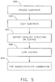
- FIG. 5 schematically represents a series of steps involved in a method for preparing a catalytic laminate for a catalyst system, according to another embodiment of the invention
- FIG. 6 is a block diagram schematically representing an air purification system incorporating a catalyst system, according to another embodiment of the invention.
- FIG. 7 is a block diagram schematically representing an exhaust system incorporating a catalyst system, according to another embodiment of the invention.
- FIG. 8 is a scanning electron micrograph showing metal particles bonded to, and protruding from, the surface of a binder layer, according to one aspect of the invention.
- the present invention provides apparatus, compositions, and methods for the catalytic removal of one or more components from a fluid stream, such as a stream of gaseous material.
- the present invention may be used for removal of contaminants from an airstream of an air circulation, or environmental control, system for providing a supply of conditioned air to an interior space of a building or an interior of a vehicle.
- a catalyst system of the invention may be used for the removal of ozone, hydrocarbons, etc., from air to be circulated to an aircraft cabin or cockpit.
- the present invention may find application in the removal of one or more components from an exhaust gas stream of an internal combustion engine. It is to be understood that the above are merely examples, and the invention is by no means limited to these applications.
- a catalyst system of the invention may comprise a catalytic laminate having a plurality of catalyst structures affixed to, and protruding from, a binder layer, wherein the catalyst structures are directly exposed to a fluid stream as the fluid stream is passed with respect to the catalyst system. Due to the direct exposure of the catalyst structures to the fluid stream, the selective removal of components from the fluid stream is more efficient, as compared with prior art catalyst systems that have catalytic material embedded or impregnated within a paste, matrix, or other supporting material. Greater efficiency of catalyst systems of the invention allow the use of lesser quantities of catalytically active material, thereby decreasing production costs. Furthermore, in catalyst systems of the invention the catalyst structures may be selectively located only at zones of the system which have optimum operating temperatures for catalytic activity, thereby further reducing production costs.
- the binder layer of the invention may be a thin, substantially uniform layer of a low thermal conductivity material.
- the direct exposure of the catalyst structures of the invention to the fluid stream, in concert with the low thermal conductivity of the binder layer, allows catalyst systems of the invention to quickly attain operating (e.g., light-off) temperature, thereby greatly reducing emissions at start up.
- the binder layer of the invention does not cause a substantial pressure drop across the system.
- the binder layer of the invention may be made sufficiently thin so as to cause substantially no decrease in thermal efficiency of a heat exchanger coated with the binder layer.
- the binder layer of the invention may be tightly bound to a metal substrate to form a protective coating which prevents oxidation of the metal.
- FIG. 1 is a cross-section of a portion of a catalytic laminate 200 of a catalyst system, according to one embodiment of the invention.
- catalytic laminate 200 includes a substrate 210 , a binder layer 220 disposed on substrate 210 , and a catalytic layer 230 disposed on binder layer 220 .
- substrate 210 may be a ceramic or a metal.
- substrate 210 may be substantially planar, or may be formed to provide various configurations. In some embodiments, substrate 210 may be configured prior to application of binder layer 220 thereto.
- Binder layer 220 may be applied to substrate 210 as a solution to provide, initially, a liquid film which may be subsequently dried and cured to form a solid coating.
- binder layer 220 may be a ceramic coating comprising a material such as zirconia, alumina, silica, or titania.
- Such ceramic coatings may be prepared from a liquid film precursor comprising an alkoxide of zirconium, aluminum, silicon, or titanium.
- Catalytic layer 230 may comprise a plurality of catalyst structures (e.g., FIGS. 2-4A ). Each catalyst structure may be a solid particle, or a filament, or the like, of a catalytically active material.
- the plurality of catalyst structures may be applied to binder layer 220 before binder layer 220 has cured, such that the catalyst structures protrude from the surface of binder layer 220 .
- at least about 50% to 95% of the total surface area of the catalyst structures protrudes from the surface of binder layer 220 , preferably at least about 60% to 95%, and more preferably at least about 70% to 95%.
- Firing of catalytic laminate 200 causes binder layer 220 to strongly bind to substrate 210 , and further causes the catalyst structures (e.g., FIG. 2 ) to be firmly bonded to binder layer 220 .
- Methods for preparing catalytic laminates of the invention will be described in enabling detail hereinbelow (e.g., with reference to FIG. 5 ).
- FIG. 2 is a cross-section of a catalytic laminate 200 schematically representing a plurality of catalyst structures 232 of a catalyst system.
- Each of catalyst structures 232 is affixed to binder layer 220 , and protrudes from binder layer surface 222 . Accordingly, catalyst structures 232 are directly exposed to a fluid stream, represented by solid arrows in FIG. 2 , to be treated by the catalyst system.
- catalytic laminate 200 may line an inner surface of airsteam ducting, a heat exchanger, etc. of an air purification system for an interior space of a vehicle or building.
- catalytic laminate 200 may be located within an exhaust system of an internal combustion engine, e.g., within an exhaust manifold and/or within a catalytic unit downstream from the exhaust manifold.
- the size, shape, and composition of catalyst structures 232 is, at least to some extent, a matter of design choice.
- Catalyst structures 232 may have a diameter in the range of from about 5 ⁇ to 200 ⁇ , preferably from about 5 ⁇ to 100 ⁇ , and more preferably from about 10 ⁇ to 50 ⁇ . As shown in FIG. 2 , catalyst structures 232 may have roughened or pitted surface to increase the surface area, and hence to provide increased exposure of catalyst structures 232 to the fluid stream to be treated. Although, catalyst structures 232 are shown in FIG. 2 as being substantially spherical, other shapes are also contemplated under the invention. For example, according to various embodiments, catalyst structures 232 may be in the form of fibers, filaments, hollow tubes, and the like (see, e.g., FIG. 4A ).
- Binder layer 220 may be a substantially uniform layer, having a fairly smooth binder layer surface 222 , and a thickness in the range of from about 0.2 ⁇ to 100 ⁇ , preferably from about 0.5 ⁇ to 10 ⁇ , and more preferably from about 0.5 ⁇ to 5 ⁇ . Binder layer 220 may be impermeable, or essentially impermeable, to the fluid stream. That is to say, binder layer 220 does not generally permit the passage therethrough of the fluid comprising the fluid stream.
- FIG. 3A is a perspective view
- FIG. 3B is a side view, of a portion of a catalytic laminate 200 showing the arrangement of catalyst structures 232 as a single layer protruding from binder layer surface 222 , according to one embodiment of the invention.
- catalyst structures 232 are schematically represented as spheres, it being understood that such structures may have various configurations and surface textures.
- the concentration, or number, of catalyst structures 232 per unit area of binder layer 220 may vary, e.g., depending on factors such as the volume or surface area of each catalyst structure 232 , the nature of the catalytic material comprising catalyst structures 232 , the intended use of the catalyst system, etc.
- catalytic laminate 200 may comprise from about 50 to 40,000 structures per mm 2 of binder layer 220 , preferably from about 100 to 15,000 structures per mm 2 , and more preferably from about 400 to 10,000 structures per mm 2 .
- catalyst structures 232 may be arranged on binder layer 220 as a substantially uniform single layer with adjacent catalyst structures 232 spaced apart from each other on binder layer 220 . In other embodiments, catalyst structures 232 may be contiguous with each other, or almost contiguous with each other.
- FIG. 3C is a side view of a portion of a catalytic laminate 200 ′, having a second layer of catalyst structures 232 ′ disposed on a first layer of catalyst structures 232 , according to another embodiment of the invention.
- Catalyst structures 232 may be affixed to binder layer 220 (e.g., as described hereinabove with reference to FIGS. 2 , 3 A-B). While not being bound by theory, applicant believes that catalyst structures 232 ′ may be bonded to a liquid precursor of binder material drawn onto portions of catalyst structures 232 prior to solidification of binder layer 220 . Catalyst structures 232 ′ may also be bonded or sintered to portions of catalyst structures 232 during firing of laminate 200 ′.
- Catalyst structures 232 ′ may be quantitatively and qualitatively the same as, or similar to, catalyst structures 232 .
- catalyst structures 232 ′ may be dissimilar to catalyst structures 232 with respect to their dimensions, configuration, chemical composition, catalytic activity, etc. In this manner, a multifunctional catalyst unit can be prepared within a single zone of a catalyst system.
- a plurality of different catalytic materials may be restricted to certain zones of a catalyst system.
- catalyst structures 232 ′, 232 are shown in FIGS. 3A-C as being substantially spherical, it is to be understood that the invention is by no means limited to substantially spherical catalyst structures.
- FIG. 4A is a side view schematically representing a portion of a catalyst system 300 having a plurality of different catalyst structures located within different zones of the catalyst system, according to another embodiment of the invention.
- FIG. 4B is a macroscopic plan view schematically representing a portion of catalyst system 300 .
- Catalyst system 300 includes first and second catalytic zones 302 a , 302 b , wherein each zone comprises a different catalytic laminate composition.
- First catalytic zone 302 a comprises a plurality of first catalyst structures 332 a affixed to, and protruding from, a binder layer surface 322 of a binder layer 320 .
- second catalytic zone 302 b comprises a plurality of second catalyst structures 332 b affixed to, and protruding from, binder layer surface 322 of binder layer 320 .
- First and second catalytic zones 302 a , 302 b may be separated by a distance, d within a catalytic unit or system (as shown).
- first and second zones 302 a , 302 b may be contiguous.
- the catalytic unit may exhibit an operating temperature gradient (represented in FIG. 4B by arrow T), such that first and second catalyst structures 332 a , 332 b are respectively located within an optimal working temperature range consistent with maximum efficiency of each catalytic zone, 302 a , 302 b .
- two catalytic zones 302 a , 302 b are shown in FIGS. 4A-B , other numbers of zones are also possible under the invention.
- FIG. 5 schematically represents a series of steps involved in a method for preparing a catalytic laminate for a catalyst system, according to another embodiment of the invention.
- Step 400 involves providing a substrate.
- the substrate may be, for example, a ceramic or a metal.
- a metal substrate may comprise, for example, stainless steel, aluminum, tin, molybdenum, platinum, tungsten, titanium, or their alloys, and the like.
- the substrate may be formed or shaped to provide various configurations according to the intended application of the catalytic laminate or catalyst system.
- Step 402 involves coating the substrate with a binder layer adapted, inter alia, for accepting, and affixing thereto, a plurality of catalyst structures.
- coating the substrate involves forming a film of a solution on the substrate, and subsequently curing the film to form a solid coating.
- a film comprises a solution of an alkoxide of silicon, titanium, aluminum, or zirconium, or mixtures thereof, in a suitable organic solvent.
- Exemplary alkoxides include zirconium butoxide and aluminum butoxide.
- Exemplary solvents include ethanol and toluene.
- Such solutions may comprise from about 5% to 95% solvent, usually from about 10% to 90% solvent, and typically from about 30% to 70% solvent, by weight/volume.
- composition and concentration of the solution may be varied to carefully control the viscosity of the solution. While not being bound by theory, applicant has observed that the viscosity of the solution may be critical in permitting appropriate coverage of the substrate with a thin, uniform layer or film of the solution. Thus, the viscosity of the solution may be critical in determining the thickness of the film formed on the substrate, and accordingly in determining the thickness of the binder layer. Solutions having relatively high viscosity tend to form relatively thick, uneven layers on a substrate, leading to problems encountered in the prior art, such as clogging of channels within heat exchangers and similar components, as well as substantial pressure drop across such components, and decreased thermal efficiency of heat exchangers.
- the solution with which the substrate is coated may have a viscosity typically less than about 200 centipoise, preferably from about 0.5 to 100 centipoise, and more preferably from about 0.5 to 50 centipoise.
- the substrate may be coated by a solution comprising an incipient or precursor binder layer, by dip coating the substrate to provide a film of the solution on the surface(s) of the substrate.
- the thickness of such a film may be controlled by varying the speed of removal of the substrate from the solution, as well as by adjusting the viscosity of the solution.
- the thickness of the coating or binder layer may be controlled by multiple dip coating of the substrate. In the latter situation, the film may be dried, cured or fired between dips.
- Step 402 may involve coating the entire surface of the substrate with the binder layer.
- the binder layer may be selectively applied to certain portions of the substrate, e.g., using a mask, or the like.
- Step 404 involves depositing a plurality of catalyst structures on the binder layer or coating.
- the catalyst structures are deposited on the coating while the film (i.e., incipient binder layer) provided in step 402 is still wet.
- the catalyst structures deposited on the coating may be particulate catalytically active materials, e.g., in the form of a powder.
- the catalyst structures may be substantially spherical, or may have elongated, e.g., ovoid, filamentous, or tubular structures. In the case of substantially spherical catalyst structures, each particle may have a rough, pitted or irregular surface so as to increase the surface area of the catalyst structure that can be exposed to a fluid stream, thereby increasing the efficiency of the catalyst system.
- the structures may be oriented with respect to the binder layer to promote exposure to the fluid stream to be treated.
- Step 404 may involve depositing the catalyst structures on the coating or binder layer by gravitational deposition, or by propelling the catalyst structures against the binder layer surface.
- Techniques for depositing solid particles on a surface are known in the art.
- Each of the plurality of catalyst structures deposited according to step 404 may comprise a catalytically active material.
- the catalyst structures may comprise a precious metal catalyst, a metal oxide catalyst, or a perovskite-type oxide catalyst.
- precious metal catalysts include: platinum, palladium, gold, silver, and ruthenium.
- metal oxide catalysts include: antimony oxide, magnesium oxide, oxides of iron (e.g., iron(III) oxide), cerium (e.g., cerium(IV) oxide), niobia, vanadia, a mixed metal oxide, or a combination of the above.
- perovskite-type catalysts are described in U.S. Pat. Nos. 5,977,017 and 5,939,354, the disclosures of which are incorporated by reference herein in their entirety.
- Step 404 typically involves depositing the catalyst structures on the binder layer in such a manner that the catalyst structures protrude from a surface of the binder layer.
- Protrusion of catalyst structures from the binder layer is associated with a number of advantages exhibited by catalyst systems of the invention, as described hereinabove.
- protrusion of catalyst structures from the binder layer allows direct exposure of a fluid stream to the catalytically active material, thereby greatly increasing efficiency of the catalyst system, and/or decreasing the required amount of catalyst material, as compared with many prior art systems.
- Direct exposure to the fluid stream also promotes more rapid attainment of light-off temperature of the catalyst structures, as compared with prior art systems in which catalytically active material is isolated and insulated from the fluid stream by a supporting matrix.
- Step 406 involves curing the coating or film of solution applied to the substrate in step 402 .
- the solution comprises an alkoxide of zirconium, silicon, titanium, or aluminum
- step 406 comprises reacting the coating with water vapor in a controlled atmosphere such that solvent is removed, and the film is transformed to a solid ceramic layer in which oxide particles are polymerized or cross-linked.
- the relative humidity of the controlled atmosphere is in the range of from about 0 (zero) % to 90%, often in the range of from about 10% to 90%, and usually in the range of from about 20% to 80%.
- Curing of the binder layer according to the invention may take from a few seconds to about 24 hours, usually from about 1 minute to 12 hours, and more typically from about 5 minutes to 4 hours.
- Factors determining the rate of curing of the binder layer include the composition of the coating solution, as well as the humidity and temperature of the atmosphere, and the rate of air flow over the coating.
- the curing stage may be performed at a temperature typically in the range of from about 15° C. to 500° C., preferably from about 100° C. to 400° C., and more preferably at a temperature greater than 100° C. to about 400° C.
- the rate of curing of the binder layer may be controlled by manipulating the composition of the solution, the temperature, and relative humidity, in order to facilitate deposition of the catalyst structures (step 404 ) before curing is complete.
- the relative humidity may initially be kept fairly low, e.g., in the range of from about 20% to 40%, in order to delay curing of the binder layer until after the catalyst structures have been deposited thereon. Thereafter, the relative humidity may be increased, e.g., to a value in the range of from about 40% to 80%, to accelerate curing of the binder layer.
- Step 408 involves firing the substrate/binder layer/catalyst structure combination to form a catalytic laminate of the invention.
- firing may be performed at a temperature in the range of from about 300° F. to 1200° F., and more typically from about 500° F. to 1000° F., and for a period in the range of from about 10 to 100 minutes, usually from about 15 to 90 minutes, and more typically from about 15 to 60 minutes.
- Firing also serves to sinter the catalyst structures to the binder layer to provide a catalytic layer in which the catalyst structures are firmly affixed to the binder layer, and at the same time the catalyst structures protrude from the binder layer.
- firing can be performed rapidly by placement in a pre-heated furnace, holding the temperature for the desired time period, and immediately thereafter removal to ambient conditions, i.e., no temperature ramp up/ramp down is required.
- a catalytic laminate prepared according to the invention has a binder layer which may withstand thermal cycling to a temperature of 1300° F. for at least 4,000 cycles.
- Air purification system 500 may include a source of an airstream 520 which may be in communication with a heat exchanger 530 and a catalyst system 540 .
- Catalyst system 540 is capable of efficiently removing one or more components from a stream of air emanating from source of airstream 520 .
- Such components may include various contaminants or pollutants, such as volatile organic compounds (VOCs), NO x , CO, O 3 , and the like.
- Catalyst system 540 may include a catalytic laminate, wherein the catalytic laminate has a plurality of catalyst structures affixed to, and protruding from, a relatively thin binder layer.
- the plurality of catalyst structures may comprise one or more catalytically active materials, as described hereinabove.
- Catalytic laminates of catalyst system 540 may have various elements, features, and characteristics as described herein for various embodiments of the invention (e.g., with reference to FIGS. 1-5 ).
- FIG. 7 is a block diagram schematically representing an exhaust system 600 , according to another embodiment of the invention.
- exhaust system 600 may be used in conjunction with an internal combustion engine, e.g., an engine of a wheeled vehicle.
- Exhaust system 600 may include an exhaust manifold 610 for receiving a stream of exhaust gases from the engine.
- Exhaust manifold 610 may be in communication with an exhaust gas conduit 620 for passage of the stream of exhaust gases therethrough.
- Exhaust system 600 may include a catalyst system 640 , which may be housed within exhaust manifold 610 .
- Exhaust system 600 may alternatively, or additionally, include a second catalyst system 640 ′. Second catalyst system 640 ′ may be housed within exhaust gas conduit 620 .
- Exhaust system 600 may further include a catalytic unit or converter 630 , and second catalyst system 640 ′ may be housed within catalytic unit 630 .
- Catalyst systems 640 , 640 ′ are capable of efficiently removing one or more components from an exhaust gas stream of an internal combustion engine. Such components may include various pollutants, such as NO x , CO, VOC's, hydrocarbons, and the like.
- Each of catalyst systems 640 , 640 ′ may include a catalytic laminate having a plurality of catalytically active solid structures protruding from the surface of a binder layer. In this manner, the catalytically active solid structures are directly exposed to the exhaust gas stream, thereby not only increasing efficiency of pollutant removal per unit of catalytically active material, but also decreasing the time required to achieve light-off temperature. As a result, emissions at start up are greatly reduced.
- a catalytic laminate of the invention may be selectively applied to key areas of exhaust manifold 610 , e.g., at key areas next to the engine. Locating the catalytic laminate very close to the engine significantly decreases the time to achieve “light-off”.
- the catalytic laminate may also be applied locally to key parts of exhaust gas conduit 620 . Since the catalytic laminate applied to exhaust gas conduit 620 will see lower temperatures, the catalytically active material applied to exhaust gas conduit 620 may be different from that applied to exhaust manifold 610 . Embodiments of catalyst laminates suitable for use in conjunction with catalyst system 600 are described hereinabove, for example, with respect to FIGS. 1-5 .
- FIG. 8 is a scanning electron micrograph (SEM) of metal particles (copper powder) bonded to a zirconia coating, clearly showing protrusion of the particles from the surface of the binder layer.
- the zirconia coating/binder layer was prepared, and the copper powder deposited thereon, generally as described with reference to FIG. 5 .
- Smooth particles of solid copper were used to demonstrate the effectiveness of the invention in affixing micro-particulate structures to the surface of a binder layer or coating.
- the binder layer was cured and fired as described hereinabove. Even at relatively high concentrations of powder per unit area of binder layer, the smooth copper particles were firmly attached to the binder layer (Example 2).
- a metal substrate was coated with a zirconia binder layer, and the binder layer bonded to the substrate, generally according to the method described hereinabove with reference to FIG. 5 .
- the binder layer exhibited no signs of flaking.
- microscopic examination of the binder layer showed no change in the appearance of the binder layer after the above thermal cycling regime.
- a substrate comprising a stainless steel plate was coated with a zirconia binder layer, generally according to the method described hereinabove with reference to FIG. 5 .
- copper powder comprising substantially spherical, smooth particles having a diameter in the range of from about 20 ⁇ to 150 ⁇ was deposited on the binder layer.
- the copper powder was found to be firmly attached to the binder layer.
- Scanning electron micrographs (SEM, at a magnification of 200 ⁇ ) showed the particles of copper as protruding from the binder layer surface having at least about 90% of their surface areas exposed ( FIG. 8 ).
- Energy dispersive X-ray (EDX) analysis of the surface of the copper particles found them to be free from traces of zirconia, the binder layer, thereby confirming that the particles would be directly exposed to fluid flow.
- EDX Energy dispersive X-ray
Abstract
A catalyst system for removing one or more components from a fluid stream includes a binder layer and a plurality of catalyst structures affixed to, and protruding from, the binder layer such that the catalyst structure surface is directly exposed to the fluid stream. Methods for preparing a catalyst system, and for selectively removing components from a fluid stream via a catalyst system are also disclosed.
Description
This is a divisional application of U.S. application Ser. No. 10/410,831 filed on Apr. 9, 2003, now U.S. Pat. No. 7,067,454, which is hereby incorporated by reference in its entirety.
The present invention generally relates to a catalyst system and methods for making a catalyst system. The present invention also relates to apparatus, compositions, and methods for selectively removing one or more components from a fluid stream via a catalyst system.
Many conventional catalyst systems and apparatus have used catalyst materials embedded or impregnated within a support matrix to form a catalyst-matrix mixture. Such mixtures have been applied to various substrates to provide catalyst systems of the prior art. When a fluid stream is passed within, or over, such catalyst-matrix mixtures, the catalytically active materials are protected from the fluid stream by the surrounding matrix, thereby limiting the effectiveness and efficiency of the catalyst in removing components from the fluid stream. Further, such catalyst-matrix mixtures have been applied to a substrate as a paste, which tends to clog the catalyst system, thereby impeding flow of the fluid stream and causing a substantial pressure drop within the system. In addition, many prior art catalyst-matrix mixtures tend to crack and lack continuity on the substrate after the mixture has dried. Furthermore, catalyst-matrix mixtures of the prior art have been deposited as relatively thick layers, such that the mixture substantially decreases the thermal efficiency of heat exchangers of a fluid circulation system.
As can be seen, there is a need for a catalyst system for the passage of a fluid stream therethrough, the catalyst system including at least one catalytically active material, wherein the at least one catalytically active material is directly exposed to the fluid stream as the fluid stream is passed with respect to the catalyst system. There is a further need for a catalyst system which provides for the efficient removal of components from a fluid stream using a relatively small amount of catalytically active material within the system. There is also a need for a catalyst system which provides for the efficient removal of components from a fluid stream while having no substantial effect on heat exchanger efficiency or pressure drop across the system. There is a further need for a catalyst system including a thermally stable binder layer, wherein at least one catalytically active material rapidly reaches light-off temperature due to direct exposure to the fluid stream. There is also a need for a system wherein a catalyst can be applied only to specific local areas of a component where it is needed and can function, rather than having to apply the catalyst to the entire component, even though it is known that most of the applied catalyst will not be used. The present invention provides such systems using low cost materials and manufacturing processes, as will be described in enabling detail hereinbelow.
In one aspect of the present invention, a catalyst system including a catalytic laminate for passage of a fluid stream thereover comprises a binder layer; and a plurality of catalyst structures disposed on the binder layer, wherein the plurality of catalyst structures protrude from a surface of the binder layer such that the plurality of catalyst structures are directly exposed to the fluid stream when the fluid stream is passed over the catalytic laminate.
In another aspect of the present invention, there is provided a method of preparing a catalyst system including a catalytic laminate for removal of one or more components from a fluid stream, wherein the method comprises: coating a substrate with a binder layer; depositing a plurality of catalyst structures on the binder layer; binding the plurality of catalyst structures to the binder layer, wherein the plurality of catalyst structures protrudes from the binder layer such that at least about 70% of the total surface area of the plurality of catalyst structures is directly exposed to the fluid stream when the fluid stream is passed over the catalytic laminate.
In another aspect of the present invention, a method for removing one or more components from a fluid stream comprises providing a catalyst system, the catalyst system having a binder layer and a plurality of catalyst structures affixed to, and protruding from, a surface of the binder layer such that at least about 50% of the total surface area of the plurality of catalyst structures is exposed to the fluid stream; passing the fluid stream over the catalyst system such that the plurality of catalyst structures are directly exposed to the one or more components; and, via the plurality of catalyst structures, removing the one or more components from the fluid stream as the fluid stream passes over the catalyst system.
In another aspect of the present invention, an exhaust system for an internal combustion engine comprises an exhaust gas conduit in communication with the engine, the exhaust gas conduit for passing a stream of exhaust gases from the engine; and a catalyst system in communication with the exhaust gas conduit, the catalyst system including a binder layer and a plurality of catalyst structures protruding from the binder layer, such that the plurality of catalyst structures are directly exposed to the stream of exhaust gases when the stream of exhaust gases passes over the catalyst system.
In another aspect of the present invention, an air purification system for an interior space comprises a source of an airstream; a catalyst system in communication with the airstream, the catalyst system comprising a catalytic laminate including a binder layer and a plurality of catalyst structures disposed on the binder layer, wherein the plurality of catalyst structures protrude from the binder layer such that at least about 70% of the total surface area of the plurality of catalyst structures is directly exposed to the airstream when the airstream is passed over the catalytic laminate.
These and other features, aspects and advantages of the present invention will become better understood with reference to the following drawings, description and claims.
The following detailed description is of the best currently contemplated modes of carrying out the invention. The description is not to be taken in a limiting sense, but is made merely for the purpose of illustrating the general principles of the invention, since the scope of the invention is best defined by the appended claims.
The present invention provides apparatus, compositions, and methods for the catalytic removal of one or more components from a fluid stream, such as a stream of gaseous material. As an example, the present invention may be used for removal of contaminants from an airstream of an air circulation, or environmental control, system for providing a supply of conditioned air to an interior space of a building or an interior of a vehicle. Thus, a catalyst system of the invention may be used for the removal of ozone, hydrocarbons, etc., from air to be circulated to an aircraft cabin or cockpit. As another example, the present invention may find application in the removal of one or more components from an exhaust gas stream of an internal combustion engine. It is to be understood that the above are merely examples, and the invention is by no means limited to these applications.
According to one embodiment, a catalyst system of the invention may comprise a catalytic laminate having a plurality of catalyst structures affixed to, and protruding from, a binder layer, wherein the catalyst structures are directly exposed to a fluid stream as the fluid stream is passed with respect to the catalyst system. Due to the direct exposure of the catalyst structures to the fluid stream, the selective removal of components from the fluid stream is more efficient, as compared with prior art catalyst systems that have catalytic material embedded or impregnated within a paste, matrix, or other supporting material. Greater efficiency of catalyst systems of the invention allow the use of lesser quantities of catalytically active material, thereby decreasing production costs. Furthermore, in catalyst systems of the invention the catalyst structures may be selectively located only at zones of the system which have optimum operating temperatures for catalytic activity, thereby further reducing production costs.
The binder layer of the invention may be a thin, substantially uniform layer of a low thermal conductivity material. The direct exposure of the catalyst structures of the invention to the fluid stream, in concert with the low thermal conductivity of the binder layer, allows catalyst systems of the invention to quickly attain operating (e.g., light-off) temperature, thereby greatly reducing emissions at start up. Unlike many prior art catalyst systems, the binder layer of the invention does not cause a substantial pressure drop across the system. In addition, the binder layer of the invention may be made sufficiently thin so as to cause substantially no decrease in thermal efficiency of a heat exchanger coated with the binder layer. Furthermore, the binder layer of the invention may be tightly bound to a metal substrate to form a protective coating which prevents oxidation of the metal.
With reference to the drawings, FIG. 1 is a cross-section of a portion of a catalytic laminate 200 of a catalyst system, according to one embodiment of the invention. As shown, catalytic laminate 200 includes a substrate 210, a binder layer 220 disposed on substrate 210, and a catalytic layer 230 disposed on binder layer 220. As an example, substrate 210 may be a ceramic or a metal. Substrate 210 may be substantially planar, or may be formed to provide various configurations. In some embodiments, substrate 210 may be configured prior to application of binder layer 220 thereto.
Step 402 involves coating the substrate with a binder layer adapted, inter alia, for accepting, and affixing thereto, a plurality of catalyst structures. In one embodiment, coating the substrate involves forming a film of a solution on the substrate, and subsequently curing the film to form a solid coating. In one embodiment, such a film comprises a solution of an alkoxide of silicon, titanium, aluminum, or zirconium, or mixtures thereof, in a suitable organic solvent. Exemplary alkoxides include zirconium butoxide and aluminum butoxide. Exemplary solvents include ethanol and toluene. Such solutions may comprise from about 5% to 95% solvent, usually from about 10% to 90% solvent, and typically from about 30% to 70% solvent, by weight/volume.
The composition and concentration of the solution may be varied to carefully control the viscosity of the solution. While not being bound by theory, applicant has observed that the viscosity of the solution may be critical in permitting appropriate coverage of the substrate with a thin, uniform layer or film of the solution. Thus, the viscosity of the solution may be critical in determining the thickness of the film formed on the substrate, and accordingly in determining the thickness of the binder layer. Solutions having relatively high viscosity tend to form relatively thick, uneven layers on a substrate, leading to problems encountered in the prior art, such as clogging of channels within heat exchangers and similar components, as well as substantial pressure drop across such components, and decreased thermal efficiency of heat exchangers. Therefore, according to the invention, the solution with which the substrate is coated may have a viscosity typically less than about 200 centipoise, preferably from about 0.5 to 100 centipoise, and more preferably from about 0.5 to 50 centipoise.
In one embodiment of the invention, the substrate may be coated by a solution comprising an incipient or precursor binder layer, by dip coating the substrate to provide a film of the solution on the surface(s) of the substrate. The thickness of such a film may be controlled by varying the speed of removal of the substrate from the solution, as well as by adjusting the viscosity of the solution. In one embodiment, the thickness of the coating or binder layer may be controlled by multiple dip coating of the substrate. In the latter situation, the film may be dried, cured or fired between dips. Step 402 may involve coating the entire surface of the substrate with the binder layer. Alternatively, the binder layer may be selectively applied to certain portions of the substrate, e.g., using a mask, or the like.
Step 404 involves depositing a plurality of catalyst structures on the binder layer or coating. Typically, the catalyst structures are deposited on the coating while the film (i.e., incipient binder layer) provided in step 402 is still wet. The catalyst structures deposited on the coating may be particulate catalytically active materials, e.g., in the form of a powder. The catalyst structures may be substantially spherical, or may have elongated, e.g., ovoid, filamentous, or tubular structures. In the case of substantially spherical catalyst structures, each particle may have a rough, pitted or irregular surface so as to increase the surface area of the catalyst structure that can be exposed to a fluid stream, thereby increasing the efficiency of the catalyst system. In the case of elongate filamentous or tubular catalyst structures, the structures may be oriented with respect to the binder layer to promote exposure to the fluid stream to be treated.
Step 404 may involve depositing the catalyst structures on the coating or binder layer by gravitational deposition, or by propelling the catalyst structures against the binder layer surface. Techniques for depositing solid particles on a surface are known in the art.
Each of the plurality of catalyst structures deposited according to step 404 may comprise a catalytically active material. As an example, the catalyst structures may comprise a precious metal catalyst, a metal oxide catalyst, or a perovskite-type oxide catalyst. Such metal and metal oxide catalysts are well known in the art. Exemplary precious metal catalysts include: platinum, palladium, gold, silver, and ruthenium. Exemplary metal oxide catalysts include: antimony oxide, magnesium oxide, oxides of iron (e.g., iron(III) oxide), cerium (e.g., cerium(IV) oxide), niobia, vanadia, a mixed metal oxide, or a combination of the above. As an example only, perovskite-type catalysts are described in U.S. Pat. Nos. 5,977,017 and 5,939,354, the disclosures of which are incorporated by reference herein in their entirety.
Step 404 typically involves depositing the catalyst structures on the binder layer in such a manner that the catalyst structures protrude from a surface of the binder layer. Protrusion of catalyst structures from the binder layer is associated with a number of advantages exhibited by catalyst systems of the invention, as described hereinabove. For example, protrusion of catalyst structures from the binder layer allows direct exposure of a fluid stream to the catalytically active material, thereby greatly increasing efficiency of the catalyst system, and/or decreasing the required amount of catalyst material, as compared with many prior art systems. Direct exposure to the fluid stream also promotes more rapid attainment of light-off temperature of the catalyst structures, as compared with prior art systems in which catalytically active material is isolated and insulated from the fluid stream by a supporting matrix.
Step 406 involves curing the coating or film of solution applied to the substrate in step 402. In embodiments in which the solution comprises an alkoxide of zirconium, silicon, titanium, or aluminum, step 406 comprises reacting the coating with water vapor in a controlled atmosphere such that solvent is removed, and the film is transformed to a solid ceramic layer in which oxide particles are polymerized or cross-linked. Typically, the relative humidity of the controlled atmosphere is in the range of from about 0 (zero) % to 90%, often in the range of from about 10% to 90%, and usually in the range of from about 20% to 80%.
Curing of the binder layer according to the invention may take from a few seconds to about 24 hours, usually from about 1 minute to 12 hours, and more typically from about 5 minutes to 4 hours. Factors determining the rate of curing of the binder layer include the composition of the coating solution, as well as the humidity and temperature of the atmosphere, and the rate of air flow over the coating. The curing stage may be performed at a temperature typically in the range of from about 15° C. to 500° C., preferably from about 100° C. to 400° C., and more preferably at a temperature greater than 100° C. to about 400° C. The rate of curing of the binder layer may be controlled by manipulating the composition of the solution, the temperature, and relative humidity, in order to facilitate deposition of the catalyst structures (step 404) before curing is complete. For example, the relative humidity may initially be kept fairly low, e.g., in the range of from about 20% to 40%, in order to delay curing of the binder layer until after the catalyst structures have been deposited thereon. Thereafter, the relative humidity may be increased, e.g., to a value in the range of from about 40% to 80%, to accelerate curing of the binder layer.
Step 408 involves firing the substrate/binder layer/catalyst structure combination to form a catalytic laminate of the invention. Typically, firing may be performed at a temperature in the range of from about 300° F. to 1200° F., and more typically from about 500° F. to 1000° F., and for a period in the range of from about 10 to 100 minutes, usually from about 15 to 90 minutes, and more typically from about 15 to 60 minutes.
During the firing stage, the binder layer undergoes densification and is bound strongly to the substrate. Firing also serves to sinter the catalyst structures to the binder layer to provide a catalytic layer in which the catalyst structures are firmly affixed to the binder layer, and at the same time the catalyst structures protrude from the binder layer. Typically, at least about 50% to 95% of the total surface area of the catalyst structures protrudes from the surface of the binder layer, preferably at least about 60% to 95%, and more preferably at least about 70% to 95%. In some embodiments, firing can be performed rapidly by placement in a pre-heated furnace, holding the temperature for the desired time period, and immediately thereafter removal to ambient conditions, i.e., no temperature ramp up/ramp down is required. A catalytic laminate prepared according to the invention has a binder layer which may withstand thermal cycling to a temperature of 1300° F. for at least 4,000 cycles.
With reference to FIG. 6 , there is shown a block diagram schematically representing an air purification or air circulation system, according to one aspect of the instant invention. Air purification system 500 may include a source of an airstream 520 which may be in communication with a heat exchanger 530 and a catalyst system 540. Catalyst system 540 is capable of efficiently removing one or more components from a stream of air emanating from source of airstream 520. Such components may include various contaminants or pollutants, such as volatile organic compounds (VOCs), NOx, CO, O3, and the like. Catalyst system 540 may include a catalytic laminate, wherein the catalytic laminate has a plurality of catalyst structures affixed to, and protruding from, a relatively thin binder layer. The plurality of catalyst structures may comprise one or more catalytically active materials, as described hereinabove. Catalytic laminates of catalyst system 540 may have various elements, features, and characteristics as described herein for various embodiments of the invention (e.g., with reference to FIGS. 1-5 ).
Each of catalyst systems 640, 640′ may include a catalytic laminate having a plurality of catalytically active solid structures protruding from the surface of a binder layer. In this manner, the catalytically active solid structures are directly exposed to the exhaust gas stream, thereby not only increasing efficiency of pollutant removal per unit of catalytically active material, but also decreasing the time required to achieve light-off temperature. As a result, emissions at start up are greatly reduced. A catalytic laminate of the invention may be selectively applied to key areas of exhaust manifold 610, e.g., at key areas next to the engine. Locating the catalytic laminate very close to the engine significantly decreases the time to achieve “light-off”. The catalytic laminate may also be applied locally to key parts of exhaust gas conduit 620. Since the catalytic laminate applied to exhaust gas conduit 620 will see lower temperatures, the catalytically active material applied to exhaust gas conduit 620 may be different from that applied to exhaust manifold 610. Embodiments of catalyst laminates suitable for use in conjunction with catalyst system 600 are described hereinabove, for example, with respect to FIGS. 1-5 .
A metal substrate was coated with a zirconia binder layer, and the binder layer bonded to the substrate, generally according to the method described hereinabove with reference to FIG. 5 . After thermal cycling of the substrate/binder layer combination to a temperature of 1300° F. every 30 minutes for 4,000 hours, the binder layer exhibited no signs of flaking. Furthermore, microscopic examination of the binder layer showed no change in the appearance of the binder layer after the above thermal cycling regime.
A substrate comprising a stainless steel plate was coated with a zirconia binder layer, generally according to the method described hereinabove with reference to FIG. 5 . Prior to curing the binder layer, copper powder comprising substantially spherical, smooth particles having a diameter in the range of from about 20μ to 150μ was deposited on the binder layer. After firing the substrate/binder/powder combination, the copper powder was found to be firmly attached to the binder layer. Scanning electron micrographs (SEM, at a magnification of 200×) showed the particles of copper as protruding from the binder layer surface having at least about 90% of their surface areas exposed (FIG. 8 ). Energy dispersive X-ray (EDX) analysis of the surface of the copper particles found them to be free from traces of zirconia, the binder layer, thereby confirming that the particles would be directly exposed to fluid flow.
It should be understood, of course, that the foregoing relates to preferred embodiments of the invention and that modifications may be made without departing from the spirit and scope of the invention as set forth in the following claims.
Claims (6)
1. An exhaust system for an internal combustion engine, comprising:
an exhaust gas conduit in communication with said engine, said exhaust gas conduit for passing a stream of exhaust gases from said engine; and
a catalyst system in communication with said exhaust gas conduit, said catalyst system comprising:
a substrate;
a binder layer formed on the substrate; and
a plurality of particulate catalyst structures affixed to a surface of said binder layer wherein:
the binder layer is interposed between the substrate and the particulate catalyst structures;
said plurality of particulate catalyst structures protrude from said surface of said binder layer such that at least about 70% of the surface area of said plurality of particulate catalyst structures is directly exposed to said stream of exhaust gases when said stream of exhaust gases passes over said catalyst system;
said particulate catalyst structures have diameters of from about 5μ to 100μ and said particulate catalyst structures are arranged as a substantially uniform layer with adjacent particulate catalyst structures spaced apart from each other on said binder layer;
said binder layer comprises a ceramic coating bound to said substrate, said binder layer having a thickness in the range of from about 0.5 to 10 microns;
said binder layer being impervious to the exhaust gases so that the substrate is not in contact with the exhaust gases; and
said particulate catalyst structures form a catalytic layer that does not contain components other than said particulate catalyst structures.
2. The exhaust system of claim 1 ;
wherein said exhaust system comprises a catalytic converter in communication with said exhaust gas conduit, and said catalytic converter comprises said catalyst system; and.
wherein the substrate is ceramic.
3. The exhaust system of claim 1 , further comprising an exhaust manifold for receiving said stream of exhaust gases from said engine, said catalyst system comprising a catalytic laminate including said substrate, said binder layer and said plurality of particulate catalyst structures, and said catalytic laminate housed within said exhaust manifold; and
wherein the substrate is stainless steel and the particulate catalyst structures are comprised of a material that is softer than stainless steel.
4. An air purification system for an interior space, comprising:
a source of an airstream;
a catalyst system in communication with said airstream, said catalyst system comprising a catalytic laminate including a substrate, a binder layer interposed between the substrate and a plurality of particulate catalyst structures disposed on said binder layer, wherein said plurality of catalyst structures protrude from said binder layer such that at least about 70% of the total surface area of said plurality of catalyst structures is directly exposed to said airstream when said airstream is passed over said catalytic laminate;
wherein said air purification system includes a heat exchanger, and said catalyst system is housed within said heat exchanger; and
wherein said particulate catalyst structures are arranged as a substantially uniform layer with adjacent particulate catalyst structures spaced apart from each other on said binder layer so that heat transfer through the binder layer and the substrate is not impeded by the particulate catalyst structures;
wherein said binder layer comprises a ceramic coating bound to said substrate, said binder layer having a thickness in the range of from about 0.5 to 10 microns; and
wherein said binder layer is impervious to the airstream so that the substrate is not exposed to oxidation by the airstream.
5. The air purification system of claim 4 , wherein said plurality of particulate catalyst structures comprises a catalytically active material that is softer than the substrate.
6. The air purification system of claim 4 , wherein said interior space is selected from the group consisting of a building interior and a vehicle interior.
Priority Applications (1)
| Application Number | Priority Date | Filing Date | Title |
|---|---|---|---|
| US11/413,855 US7732368B2 (en) | 2003-04-09 | 2006-04-27 | Low cost quick response catalyst system |
Applications Claiming Priority (2)
| Application Number | Priority Date | Filing Date | Title |
|---|---|---|---|
| US10/410,831 US7067454B2 (en) | 2003-04-09 | 2003-04-09 | Low cost quick response catalyst system |
| US11/413,855 US7732368B2 (en) | 2003-04-09 | 2006-04-27 | Low cost quick response catalyst system |
Related Parent Applications (1)
| Application Number | Title | Priority Date | Filing Date |
|---|---|---|---|
| US10/410,831 Division US7067454B2 (en) | 2003-04-09 | 2003-04-09 | Low cost quick response catalyst system |
Publications (2)
| Publication Number | Publication Date |
|---|---|
| US20060194697A1 US20060194697A1 (en) | 2006-08-31 |
| US7732368B2 true US7732368B2 (en) | 2010-06-08 |
Family
ID=33130853
Family Applications (2)
| Application Number | Title | Priority Date | Filing Date |
|---|---|---|---|
| US10/410,831 Expired - Fee Related US7067454B2 (en) | 2003-04-09 | 2003-04-09 | Low cost quick response catalyst system |
| US11/413,855 Expired - Fee Related US7732368B2 (en) | 2003-04-09 | 2006-04-27 | Low cost quick response catalyst system |
Family Applications Before (1)
| Application Number | Title | Priority Date | Filing Date |
|---|---|---|---|
| US10/410,831 Expired - Fee Related US7067454B2 (en) | 2003-04-09 | 2003-04-09 | Low cost quick response catalyst system |
Country Status (1)
| Country | Link |
|---|---|
| US (2) | US7067454B2 (en) |
Families Citing this family (12)
| Publication number | Priority date | Publication date | Assignee | Title |
|---|---|---|---|---|
| US20060030481A1 (en) * | 2004-08-04 | 2006-02-09 | Labarge William J | Exhaust treatment device and methods of making the same |
| US7735224B2 (en) * | 2004-09-01 | 2010-06-15 | Jw Aluminum Company | Methods of applying ozone-depleting catalysts to air stream components |
| US7669327B2 (en) * | 2004-09-01 | 2010-03-02 | Jw Aluminum Company | Methods of applying ozone-depleting catalysts to heat exchangers |
| KR100696622B1 (en) * | 2005-10-19 | 2007-03-19 | 삼성에스디아이 주식회사 | Micro reforming reactor for fuel cell and method for preparating the same |
| US8043658B2 (en) * | 2007-10-08 | 2011-10-25 | GM Global Technology Operations LLC | Resistive heater geometry and regeneration method for a diesel particulate filter |
| US8304366B2 (en) * | 2010-11-24 | 2012-11-06 | Ford Global Technologies, Llc | System for remediating emissions and method of use |
| US10573610B2 (en) * | 2014-05-19 | 2020-02-25 | Catlam, Llc | Method for wafer level packaging |
| US10849233B2 (en) | 2017-07-10 | 2020-11-24 | Catlam, Llc | Process for forming traces on a catalytic laminate |
| US10349520B2 (en) | 2017-06-28 | 2019-07-09 | Catlam, Llc | Multi-layer circuit board using interposer layer and conductive paste |
| US10765012B2 (en) | 2017-07-10 | 2020-09-01 | Catlam, Llc | Process for printed circuit boards using backing foil |
| US10827624B2 (en) | 2018-03-05 | 2020-11-03 | Catlam, Llc | Catalytic laminate with conductive traces formed during lamination |
| CN114432878B (en) * | 2020-11-06 | 2023-06-16 | 佛山市顺德区美的电热电器制造有限公司 | Air purifying assembly, preparation method thereof and electric appliance |
Citations (17)
| Publication number | Priority date | Publication date | Assignee | Title |
|---|---|---|---|---|
| US3900429A (en) * | 1973-02-14 | 1975-08-19 | Toyoda Chuo Kenkyusho Kk | Catalyst for purifying exhaust gases |
| US3900602A (en) | 1970-05-15 | 1975-08-19 | Siemens Ag | Method and device for the manufacture of catalytic layers for electrodes in electrochemical cells, particularly fuel cells |
| US3966645A (en) * | 1974-02-22 | 1976-06-29 | United Kingdom Atomic Energy Authority | Catalyst |
| US4207291A (en) | 1978-04-03 | 1980-06-10 | Mcdonnell Douglas Corporation | Ozone removal filter having manganese dioxide coated thereon |
| US4665973A (en) * | 1984-12-21 | 1987-05-19 | The Garrett Corporation | Environmental control system |
| US5080882A (en) | 1989-03-10 | 1992-01-14 | Sakai Chemical Industry Co., Ltd. | Methods of ozone decomposition and catalyst structures used therein |
| US5158654A (en) | 1989-05-19 | 1992-10-27 | Sakai Chemical Industry Co., Ltd. | Ozone decomposing reactor and regeneration thereof |
| US5187137A (en) * | 1990-09-29 | 1993-02-16 | Nippon Shokubai Co., Ltd. | Catalyst and method of preparing the catalyst |
| US5422331A (en) | 1994-02-25 | 1995-06-06 | Engelhard Corporation | Layered catalyst composition |
| US5939354A (en) | 1996-04-10 | 1999-08-17 | Catalytic Solutions, Inc. | Perovskite-type metal oxide compounds and method for preparing the compounds |
| US5977017A (en) | 1996-04-10 | 1999-11-02 | Catalytic Solutions, Inc. | Perovskite-type metal oxide compounds |
| US5979157A (en) * | 1996-08-15 | 1999-11-09 | Toyota Jidosha Kabushiki Kaisha | Method and a device for purifying exhaust gas of an internal combustion engine |
| US6281159B1 (en) * | 2000-06-08 | 2001-08-28 | Howard A. Fromson | Method of forming catalyst structure with catalyst particles forged into substrate surface |
| US6280691B1 (en) * | 1997-03-31 | 2001-08-28 | Alliedsignal Inc. | Indoor air purification system |
| US6330947B1 (en) | 1999-03-30 | 2001-12-18 | Ultra-Sun Technologies, Inc | Method of manufacturing a filter |
| US20020004455A1 (en) * | 2000-06-05 | 2002-01-10 | Tomohiko Nakanishi | Ceramic carrier and ceramic catalyst body |
| US20020068025A1 (en) * | 2000-12-04 | 2002-06-06 | Foster Michael Ralph | Catalytic converter |
Family Cites Families (25)
| Publication number | Priority date | Publication date | Assignee | Title |
|---|---|---|---|---|
| US3507644A (en) * | 1966-04-04 | 1970-04-21 | Miller & Co | Titanium additive and method of use thereof |
| US4130452A (en) * | 1977-05-10 | 1978-12-19 | Indri John L | Process of constructing a ceramic catalyst support |
| DE3033194A1 (en) * | 1980-09-03 | 1982-04-01 | Werner Keßl, Gießereibedarf GmbH, 8481 Bärnwinkel | METHOD FOR THE HOMOGENIZATION OF CAST IRON MELT AND PRESSELS FOR ITS IMPLEMENTATION |
| FR2501065B1 (en) * | 1981-03-09 | 1986-02-07 | Pro Catalyse | IMPROVED CATALYST AND METHOD FOR THE TREATMENT OF EXHAUST GASES FROM INTERNAL COMBUSTION ENGINES |
| FR2530489B1 (en) * | 1982-07-26 | 1987-02-27 | Pro Catalyse | PROCESS FOR THE MANUFACTURE OF CATALYSTS FOR THE TREATMENT OF EXHAUST GASES FROM INTERNAL COMBUSTION ENGINES |
| US5097843A (en) * | 1990-04-10 | 1992-03-24 | Siemens-Pacesetter, Inc. | Porous electrode for a pacemaker |
| US5525570A (en) * | 1991-03-09 | 1996-06-11 | Forschungszentrum Julich Gmbh | Process for producing a catalyst layer on a carrier and a catalyst produced therefrom |
| DE4236727C2 (en) * | 1992-10-30 | 1997-02-06 | Sueddeutsche Kalkstickstoff | Melting agent and its use |
| JPH10111660A (en) * | 1996-10-01 | 1998-04-28 | Minnesota Mining & Mfg Co <3M> | Retroreflective sheet and its production |
| JPH10189909A (en) * | 1996-12-27 | 1998-07-21 | Texas Instr Japan Ltd | Dielectric capacitor and dielectric memory and manufacture thereof |
| US6022825A (en) * | 1998-01-08 | 2000-02-08 | Johnson Matthey Public Limited Company | Thermally durable low H2 S three-way catalysts |
| US6015285A (en) * | 1998-01-30 | 2000-01-18 | Gas Research Institute | Catalytic combustion process |
| US6583022B1 (en) * | 1998-08-27 | 2003-06-24 | Micron Technology, Inc. | Methods of forming roughened layers of platinum and methods of forming capacitors |
| DE19847008A1 (en) * | 1998-10-13 | 2000-04-20 | Degussa | Nitrogen oxide storage catalytic converter |
| DE60043522D1 (en) * | 1999-08-20 | 2010-01-28 | Mitsubishi Motors Corp | Catalyst for the purification of exhaust gases |
| US6214765B1 (en) * | 1999-11-02 | 2001-04-10 | Howard A. Fromson | Catalyst product and method of manufacture |
| ES2242673T3 (en) * | 2000-03-28 | 2005-11-16 | UMICORE AG & CO. KG | SINGLE LAYER HIGH PERFORMANCE CATALYST. |
| JP3443656B2 (en) * | 2000-05-09 | 2003-09-08 | 独立行政法人産業技術総合研究所 | Photocatalyst coloring member and method of manufacturing the same |
| JP4573993B2 (en) * | 2000-11-09 | 2010-11-04 | 日産自動車株式会社 | Exhaust gas purification catalyst and method for producing the same |
| US7276212B2 (en) * | 2001-10-01 | 2007-10-02 | Engelhard Corporation | Exhaust articles for internal combustion engines |
| US6793708B1 (en) * | 2001-10-16 | 2004-09-21 | Jeremy A. T. Jones | Slag composition |
| US6764665B2 (en) * | 2001-10-26 | 2004-07-20 | Engelhard Corporation | Layered catalyst composite |
| FR2832995B1 (en) * | 2001-12-04 | 2004-02-27 | Thales Sa | CATALYTIC GROWTH PROCESS OF NANOTUBES OR NANOFIBERS COMPRISING A DIFFUSION BARRIER OF THE NISI ALLOY TYPE |
| US20040037972A1 (en) * | 2002-08-22 | 2004-02-26 | Kang Simon | Patterned granulized catalyst layer suitable for electron-emitting device, and associated fabrication method |
| KR100527943B1 (en) * | 2003-06-04 | 2005-11-09 | 현대자동차주식회사 | Method for manufacturing double layer coated Pd only three way catalyst |
-
2003
- 2003-04-09 US US10/410,831 patent/US7067454B2/en not_active Expired - Fee Related
-
2006
- 2006-04-27 US US11/413,855 patent/US7732368B2/en not_active Expired - Fee Related
Patent Citations (18)
| Publication number | Priority date | Publication date | Assignee | Title |
|---|---|---|---|---|
| US3900602A (en) | 1970-05-15 | 1975-08-19 | Siemens Ag | Method and device for the manufacture of catalytic layers for electrodes in electrochemical cells, particularly fuel cells |
| US3900429A (en) * | 1973-02-14 | 1975-08-19 | Toyoda Chuo Kenkyusho Kk | Catalyst for purifying exhaust gases |
| US3966645A (en) * | 1974-02-22 | 1976-06-29 | United Kingdom Atomic Energy Authority | Catalyst |
| US4207291A (en) | 1978-04-03 | 1980-06-10 | Mcdonnell Douglas Corporation | Ozone removal filter having manganese dioxide coated thereon |
| US4665973A (en) * | 1984-12-21 | 1987-05-19 | The Garrett Corporation | Environmental control system |
| US5080882A (en) | 1989-03-10 | 1992-01-14 | Sakai Chemical Industry Co., Ltd. | Methods of ozone decomposition and catalyst structures used therein |
| US5158654A (en) | 1989-05-19 | 1992-10-27 | Sakai Chemical Industry Co., Ltd. | Ozone decomposing reactor and regeneration thereof |
| US5187137A (en) * | 1990-09-29 | 1993-02-16 | Nippon Shokubai Co., Ltd. | Catalyst and method of preparing the catalyst |
| US5422331A (en) | 1994-02-25 | 1995-06-06 | Engelhard Corporation | Layered catalyst composition |
| US5620672A (en) | 1994-02-25 | 1997-04-15 | Engelhard Corporation | Layered catalyst composition |
| US5939354A (en) | 1996-04-10 | 1999-08-17 | Catalytic Solutions, Inc. | Perovskite-type metal oxide compounds and method for preparing the compounds |
| US5977017A (en) | 1996-04-10 | 1999-11-02 | Catalytic Solutions, Inc. | Perovskite-type metal oxide compounds |
| US5979157A (en) * | 1996-08-15 | 1999-11-09 | Toyota Jidosha Kabushiki Kaisha | Method and a device for purifying exhaust gas of an internal combustion engine |
| US6280691B1 (en) * | 1997-03-31 | 2001-08-28 | Alliedsignal Inc. | Indoor air purification system |
| US6330947B1 (en) | 1999-03-30 | 2001-12-18 | Ultra-Sun Technologies, Inc | Method of manufacturing a filter |
| US20020004455A1 (en) * | 2000-06-05 | 2002-01-10 | Tomohiko Nakanishi | Ceramic carrier and ceramic catalyst body |
| US6281159B1 (en) * | 2000-06-08 | 2001-08-28 | Howard A. Fromson | Method of forming catalyst structure with catalyst particles forged into substrate surface |
| US20020068025A1 (en) * | 2000-12-04 | 2002-06-06 | Foster Michael Ralph | Catalytic converter |
Also Published As
| Publication number | Publication date |
|---|---|
| US20060194697A1 (en) | 2006-08-31 |
| US20040202589A1 (en) | 2004-10-14 |
| US7067454B2 (en) | 2006-06-27 |
Similar Documents
| Publication | Publication Date | Title |
|---|---|---|
| US7732368B2 (en) | Low cost quick response catalyst system | |
| EP1089820B1 (en) | Monolithic catalysts and related process for manufacture | |
| US7476417B2 (en) | Method of manufacturing monolithic catalysts | |
| US5620672A (en) | Layered catalyst composition | |
| US5510086A (en) | Adcat exhaust treatment device | |
| DE69733302T2 (en) | Catalyst for exhaust gas purification and exhaust gas purification system | |
| KR20060105737A (en) | Honeycomb structure | |
| WO2001036097A1 (en) | Catalyst and method for preparation thereof | |
| CA1137876A (en) | Catalyst supports | |
| HU212759B (en) | Method for purifying exhaust gas by means of catalysts with improved cold starting characteristics | |
| WO2014067186A1 (en) | Noble metal-integrated catalyst and preparation method therefor | |
| CN101053736B (en) | Treating method of air containing organic solvent | |
| US20220203337A1 (en) | Exhaust gas-purification catalyst having multi-layer structure including precious metal thin layer as top layer, and method for producing same | |
| JP4758081B2 (en) | Catalyst body, catalyst body for exhaust gas purification, and method for producing catalyst body | |
| JP4269665B2 (en) | Exhaust gas purification catalyst manufacturing method and exhaust gas purification catalyst | |
| WO1998011978A1 (en) | Catalytic method | |
| JP4259253B2 (en) | Exhaust gas purification catalyst and method for producing the same | |
| JP5412104B2 (en) | Exhaust gas purification catalyst | |
| WO2004067171A1 (en) | Petrol engine exhaust catalyst | |
| JP2004167460A (en) | Production method of catalyst for exhaust gas cleaning | |
| US11801491B1 (en) | Three-way catalyst with reduced palladium loading and method of making the three-way catalyst | |
| JPH10151357A (en) | Production of catalyst | |
| JPH04110045A (en) | Catalyst body for purification of exhaust gas and its production | |
| EP4355485A1 (en) | A catalytically active product and a method of producing such a catalytically active product | |
| JP2005349293A (en) | Method of manufacturing catalyst for purification of exhaust gas |
Legal Events
| Date | Code | Title | Description |
|---|---|---|---|
| REMI | Maintenance fee reminder mailed | ||
| LAPS | Lapse for failure to pay maintenance fees | ||
| STCH | Information on status: patent discontinuation |
Free format text: PATENT EXPIRED DUE TO NONPAYMENT OF MAINTENANCE FEES UNDER 37 CFR 1.362 |
|
| FP | Expired due to failure to pay maintenance fee |
Effective date: 20140608 |