US7734856B2 - Method for operating a plurality of arbiters and arbiter system - Google Patents
Method for operating a plurality of arbiters and arbiter system Download PDFInfo
- Publication number
- US7734856B2 US7734856B2 US11/842,965 US84296507A US7734856B2 US 7734856 B2 US7734856 B2 US 7734856B2 US 84296507 A US84296507 A US 84296507A US 7734856 B2 US7734856 B2 US 7734856B2
- Authority
- US
- United States
- Prior art keywords
- arbiter
- arbiters
- arbitration
- request
- signal
- Prior art date
- Legal status (The legal status is an assumption and is not a legal conclusion. Google has not performed a legal analysis and makes no representation as to the accuracy of the status listed.)
- Active, expires
Links
Images


Classifications
-
- G—PHYSICS
- G06—COMPUTING; CALCULATING OR COUNTING
- G06F—ELECTRIC DIGITAL DATA PROCESSING
- G06F13/00—Interconnection of, or transfer of information or other signals between, memories, input/output devices or central processing units
- G06F13/14—Handling requests for interconnection or transfer
- G06F13/36—Handling requests for interconnection or transfer for access to common bus or bus system
-
- G—PHYSICS
- G06—COMPUTING; CALCULATING OR COUNTING
- G06F—ELECTRIC DIGITAL DATA PROCESSING
- G06F13/00—Interconnection of, or transfer of information or other signals between, memories, input/output devices or central processing units
- G06F13/14—Handling requests for interconnection or transfer
- G06F13/16—Handling requests for interconnection or transfer for access to memory bus
- G06F13/1605—Handling requests for interconnection or transfer for access to memory bus based on arbitration
- G06F13/161—Handling requests for interconnection or transfer for access to memory bus based on arbitration with latency improvement
- G06F13/1615—Handling requests for interconnection or transfer for access to memory bus based on arbitration with latency improvement using a concurrent pipeline structrure
Definitions
- resources are shared by more than one units or devices.
- a plurality of masters may share a common slave
- a plurality of units may share a common bus
- a plurality of processors may share a common memory or pieces of information such as data packets may be transferred over a common data channel.
- Arbitration is a process, where a unit is given priority over another unit (or a plurality of other units).
- Many arbitration techniques with different degrees of fairness for the requesters and different degrees of complexity are known. Arbitration may take for example into account the number of previous requests by a given unit or the identity of the unit (i.e. the identity of the port.
- fair arbitration techniques may take into consideration that requesters are handled fair and one requester is for example not blocked by another requester. Fair arbitration techniques include for example round robin arbitration (RR), weighted round robin (WRR) or deficit round robin (DRR).
- RR round robin arbitration
- WRR weighted round robin
- DRR deficit round robin
- FIG. 1 shows a block diagram according to an embodiment of the present invention
- FIG. 2 shows a block diagram according to an embodiment of the present invention
- FIG. 3 shows a block diagram according to an embodiment of the present invention
- FIGS. 4 a and 4 b show block diagrams according to an embodiment of the present invention.
- FIGS. 5 a to 5 f shows exemplary block diagrams to illustrate an operation according to an embodiment of the present invention
- FIGS. 6 a to 6 f shows exemplary block diagrams to illustrate an operation according to an embodiment of the present invention
- FIG. 7 shows a block diagram according to an embodiment of the present invention.
- FIGS. 8 a to 8 f shows exemplary block diagrams to illustrate an operation according to an embodiment of the present invention
- FIGS. 9 a to 9 f shows exemplary block diagrams to illustrate an operation according to an embodiment of the present invention.
- FIG. 10 shows a block diagram according to an embodiment of the present invention.
- embodiments of the present invention provide for arbitration by using a plurality of arbiters or sub-arbiters.
- the plurality of sub-arbiters may be arranged in a hierarchical architecture and may be operated in pipelined or non-pipelined operation as will become clearer by the appended figures and the description explained below.
- a basic block diagram of embodiments of the present invention includes a plurality of requesters 100 which are coupled to a plurality of inputs 102 a of an arbitration system 102 to transfer requests to the arbitration system 102 .
- An output 102 b of the arbitration system 102 is coupled to a shared resource 104 to allow data transfer from the requester granted for access to the shared resource.
- arbitration system 102 may according to embodiments be comprised of a plurality of arbiters or sub-arbiters which may be operated in both, a pipelined operation and non-pipelined operation.
- the plurality of arbiters may be implemented in a hierarchical architecture.
- the plurality of requesters 100 may include any device, unit, circuit etc. which shares the resource 104 with one or more other devices, units, circuits etc.
- the plurality of requesters 100 may for example include but is not limited to memory controllers, processors and processing resources including dedicated processors, bus controllers, network controller including but not limited to wired network controller, wireless network controller, Ethernet network controllers etc, shared bus, shared memory resources including caches, DRAM etc, application accelerators, data acquisition devices etc.
- the plurality of requesters may comprise only one type of requesters, for example only a plurality of processors of a same type or may include different types of requesters, for example processors and dedicated processors.
- the shared resource 104 may be any device, unit, circuit etc. which can be shared by more than one device, unit or circuit, etc.
- the shared resource may for example be a memory, a bus, a data port, a data channel etc.
- the plurality of requesters and the shared resource may form a master-slave system, wherein the plurality of requesters are masters of a same or different type and the shared resource is a slave.
- FIG. 2 shows an exemplary implementation of the arbitration system 102 in hierarchical arbitration architecture according to an embodiment of the present invention.
- the hierarchical arbitration architecture comprises a plurality of arbitration nodes 200 .
- the plurality of arbitration nodes 200 is arranged in different hierarchical stages such that each of the arbitration nodes 200 is assigned to one stage of the hierarchical arbitration architecture.
- An arbitration node assigned to a stage is connected downwards in the hierarchy to the outputs of one or more arbitration nodes of a lower-level stage and upwards in the hierarchy to an arbitration node of a higher-level stage.
- the arbitration nodes of the lowest-level stage are connected to the requesters.
- the arbitration nodes form a tree-like structure wherein each node is coupled to a node of a higher stage except that the arbitration node at the highest level, i.e. the arbitration node at the top of the hierarchical architecture is coupled to the output 102 b of the arbitration system 102 .
- the arbitration nodes 200 at the lowest level stage (Stage 1 ) are coupled to the inputs 102 a of the arbitration system 102 .
- Each of the arbitration nodes 200 at the lowest-level stage can be coupled to one or more of the requesters 100 to receive request signals from each of requesters 100 .
- FIG. 2 shows an exemplary implementation with three stages wherein the first stage comprises five arbitration nodes and the second stage comprises two arbitration nodes
- the number of stages and the number of arbitration nodes within one stage may be varied in other embodiments.
- the number of arbitration nodes which are assigned or coupled to an arbitration node of a higher level stage may be varied in other embodiments.
- the number of arbitration nodes assigned to an arbitration node at a higher level may be the same or may be different for each arbitration node of a particular stage. For example, as shown in FIG. 2 , one of the arbitration nodes at stage 2 has assigned three arbitration nodes of stage 1 while the other arbitration node has assigned only two arbitration nodes of stage 1 .
- the hierarchical arbitration system 102 may include hierarchical arbitration request architecture and hierarchical data path architecture.
- each of the arbitration nodes 200 comprises an arbitration request node implemented by an arbiter (or arbiter circuit) 300 and a data path request node implemented in an embodiment by a multiplexer 302 shown in FIG. 3 .
- the arbiter 300 comprises a plurality of inputs 300 a corresponding to the number of arbitration nodes at the next lower stage assigned to the respective arbitration node such that each input 300 a is connected to a corresponding output of the arbiter 300 at the next lower-level stage.
- an output 300 b of the arbiter 300 is connected to an input of an arbiter 300 corresponding to an arbitration node at a higher-level stage.
- the multiplexer 302 comprises a plurality of data path inputs 302 a coupled to outputs of multiplexers at lower-level stages and an output 302 b coupled to an input of a multiplexer at a higher-level stage.
- the arbiter 300 is coupled to a register 304 to store information identifying which of the input ports competing in an arbitration process of the arbiter 300 has been granted.
- the register 304 is further coupled to a control input of the multiplexer 302 to switch the data path corresponding to information stored in the register. According to embodiments, the multiplexers are switched according to the information stored in the register 304 .
- a hierarchical arbitration request architecture for making grant decisions in arbitration processes and a hierarchical data path architecture for transferring data from granted requesters to the shared resource is obtained.
- FIGS. 4 a and 4 b show an exemplary embodiment of hierarchical arbitration request architecture and hierarchical data path architecture.
- FIGS. 4 a and 4 b correspond to a system with three arbitration nodes at stage 1 and two arbitration nodes at stage 2 .
- Each of the arbitration nodes at stage 1 has four inputs corresponding to the number of requesters M 1 . . . M 12 assigned to a respective one of the arbitration nodes.
- the plurality of arbiters, the plurality of requesters and the plurality of multiplexers of the arbitration system may according to embodiments provided on a same chip. Furthermore, according to embodiments, the arbitration system may be clocked synchronously.
- the arbiter 300 may be provided fully in hardware (hardware circuits on chip), or partially in hardware and software/firmware. Furthermore, any known arbitration technique may be implemented by the arbiter 300 in order to provide arbitration among its inputs. For example, fair arbitration techniques such as round robin arbitration (RR), weighted round robin (WRR) or deficit round robin (DRR) may be implemented by arbiter 300 . According to embodiments, the arbiter 300 may comprise a “memory” to take into account “older” active requests which have not yet been granted by the arbiter 300 .
- RR round robin arbitration
- WRR weighted round robin
- DRR deficit round robin
- the arbiter 300 may comprise a “memory” to take into account “older” active requests which have not yet been granted by the arbiter 300 .
- FIGS. 5 a to 5 f and FIGS. 6 a to 6 f A first exemplary operation of the arbitration system of FIGS. 4 a and 4 b corresponding to a pipelined operation mode will now be described with reference to FIGS. 5 a to 5 f and FIGS. 6 a to 6 f.
- the pipelined operation mode or pipelining operation or pipeline mode corresponds to an operation wherein the process to provide grant for a given requester is split into a plurality of sub-processes each performed at one of the arbiters in the arbitration system.
- Each sub-process receives as input the result from a previous stage and performs its dedicated sub process.
- the process is handed in the pipeline from one stage to another such that by the last sub-process the total process, i.e. the overall arbitration for the request reaching the top-level, is finished.
- Pipelining operation is performed in a hierarchical arbitration system in that at a given cycle at each stage of the hierarchical arbitration system, arbitration is processed among the inputs of the arbiters. Based on a grant given by an arbiter to one of the inputs, a signal, i.e. pipeline request, is then transferred as input signal to an arbiter of the next higher stage where it may compete with other input signals from other arbiters. In the next cycle, the arbiter at the next higher-level stage then arbitrates based on the requests which are active at this arbiter, i.e. which have been received and/or stored by the arbiter. The branch which has been granted by the arbiter is stored in the corresponding register.
- FIGS. 5 a to 5 f and 6 a to 6 f showing an exemplary pipelined operation.
- FIG. 5 a shows the arbitration request architecture at a cycle 0 when all of the plurality of arbiters are idle, for example after a start-up.
- the inputs of arbiter A 11 , A 12 and A 13 at the first stage are labeled and referred to according to the number of the requester coupled to the input, i.e. arbiter A 11 has inputs 1 to 4 , arbiter has inputs 5 to 8 and arbiter A 13 has inputs 9 to 12 .
- arbiters A 21 , A 22 and A 31 all containing in the described embodiment two inputs, the first input is referred to as 1 and the second is referred to 2 , as seen in FIG. 5 a.
- requester M 2 and requester M 7 both output a request signal to corresponding inputs of arbiters A 11 and A 12 at stage 1 of the arbitration system.
- arbiter A 11 performs an arbitration process and grants the request at the second input corresponding to M 2 as no other request is active for arbiter A 11 in cycle 1 .
- arbiter A 12 performs an arbitration process and grants the request at the second input corresponding to M 7 as no other request is active for arbiter A 12 in cycle 1 .
- the result indicating which input has been granted i.e.
- each of the arbiters A 11 and A 12 output a request signal to arbiter A 21 of the next higher stage which will be arbitrated in the next cycle.
- the request granted thereby drops one stage further in the hierarchical system.
- arbiter 21 has two requests active corresponding to the inputs coupled to arbiters A 11 and A 12 . Transfers of requests from arbiters are indicated in the Figures also by arrows. As can be seen in FIGS. 5 a and 5 b , due to the pipeline operation, an “intercycle” arrow is shown indicating the transfer from arbiter A 11 to arbiter A 21 .
- arbiter A 21 In the arbitration process of cycle 2 , arbiter A 21 then grants the request coming from arbiter A 11 and the information corresponding to the granted input, i.e. 1, is stored in the register of A 21 after the arbitration is finished, for example at the end of the cycle. A request signal is then output by arbiter A 21 to the arbiter A 31 at the next higher-level stage. Furthermore, in cycle 2 new requests are output by requesters M 1 , M 6 and M 9 to arbiters A 11 , A 12 and A 13 , respectively, and are granted in the arbitration process at the respective arbiters. At the end of cycle 2 , information regarding the granted requests is transferred to the corresponding registers.
- both inputs corresponding to A 11 and A 12 have active requests.
- the active request at the input corresponding to A 12 is the old request already active at cycle 2 which has not been granted in the arbitration process of cycle 2 at arbiter A 21 while the request at the input corresponding to A 11 is the new request transferred from A 11 .
- Arbiter A 21 arbitrates among the requests and gives grant to the input corresponding to A 12 , thereby removing the active request initiated from A 12 .
- arbiter A 22 processes arbitration and grants the only active request from A 13 . As described above, after granting, each of the arbiters outputs a request signal to the next higher stage unless there is an old request blocking the output of the request to the next stage as will be described below.
- cycle 3 new requests are output by requesters M 1 , M 6 to arbiters A 11 and A 12 .
- arbiter A 11 performs in cycle 3 arbitration while arbiter A 12 is blocked for arbitration in this cycle which is indicated by a gray color of arbiter A 12 .
- Arbiter A 12 is blocked because only one request can be active at a given time (cycle O at one input).
- the request granted by arbiter A 12 in the previous cycle 2 can not be transferred to arbiter A 21 because arbiter A 21 did not grant the request active at the input corresponding to arbiter A 12 in the previous cycle and this old request is therefore still active at arbiter A 12 .
- the request is therefore maintained at the output of arbiter A 12 in cycle 3 as indicated in FIG. 5 d .
- the information stored in the register of A 12 is not changed.
- the information stored in the corresponding registers are updated at the end of the cycle according to the inputs granted in the respective arbiters.
- arbiter A 11 has not been able to transfer the request from A 11 to A 21 and therefore the request is maintained at the output of arbiter A 11 as outlined in FIG. 5 e and arbiter A 11 is blocked in this cycle.
- FIG. 6 a shows the data path system at cycle 1 . It is to be noted here that FIG. 6 a starts at cycle 1 while FIG. 5 a shows the arbitration request system at cycle 0 which takes into account that data can be processed after a grant by the overall system only one cycle later.
- all of the multiplexer are in an idle or indefinite state as at the beginning of cycle 1 no information is stored in the registers which would allow the multiplexers to make corresponding switchings.
- the register associated with A 11 contains at the beginning of cycle 2 the information identifying input 2 as the granted input, compare for the information stored in the registers shown FIG. 5 b .
- multiplexer D 11 sets its second input active.
- the register corresponding to A 12 contains at the beginning of cycle 2 the information identifying input 7 as the granted input and multiplexer D 12 sets the input corresponding to M 7 active.
- the setting of the multiplexer D 11 allows data from M 2 to be transferred one stage further in the system, i.e. to the input of multiplexer D 21 as shown in FIG. 6 b .
- the setting of multiplexer D 12 allows data from M 7 to be transferred to the corresponding input of multiplexer D 21 .
- multiplexer D 11 sets the input corresponding to M 1 active
- multiplexer D 12 sets the input corresponding to M 6 active
- multiplexer D 21 sets the input coupled to D 11 active in correspondence with the information stored in the registers, compare for FIG. 5 c .
- multiplexer D 13 sets its input corresponding to M 9 active.
- the data from M 2 is then transferred in accordance with the setting of multiplexer D 21 one stage further in the hierarchical data system, i.e. from the input of multiplexer D 21 to the input of multiplexer D 31 , as outlined in FIG. 6 c .
- data from M 1 is transferred to the input of multiplexer D 21 according to the setting of multiplexer D 11 . It is to be noted that no data is transferred from D 12 to D 21 as the old data M 7 is still active at the input of multiplexer D 21 .
- cycle 4 shown in FIG. 6 d , the multiplexers are set in correspondence with the information stored in its register (see FIG. 5 c ). It can be seen from FIG. 6 d that with the setting of the top-level multiplexer a data path corresponding to a branch through the hierarchical data path system, i.e. a data path from requester M 2 to the shared source has finally been completed. Data from requester M 2 are therefore transferred in this cycle to the shared source.
- data from M 7 is transferred from multiplexer D 21 to multiplexer D 31 in accordance with the setting of multiplexer D 21 while data from M 6 is transferred to the input of multiplexer D 21 and data from M 9 is transferred to the input of multiplexer D 22 .
- cycle 5 shown in FIG. 6 e , the data from M 7 is finally transferred to the shared source while the data from M 1 , M 4 , M 9 and M 10 each advance one stage further in the data path system.
- data from M 9 is transferred to the shared source while data from M 10 and M 9 is transferred one stage further in the pipeline, i.e. from multiplexer D 22 to the input of multiplexer D 31 and from multiplexer D 13 to the input of multiplexer M 22 .
- the arbitration system may not only be capable of providing pipelined operation but also to provide a fast arbitration when needed.
- the arbitration system may provide a selective non-pipelined arbitration of a request in at least a part of the arbiters when needed.
- the non-pipelined arbitration may be a parallel arbitration and may be selected when arbiters have been idle as will be described below.
- parallel arbitration a specific request of a requester or a specific request of an arbiter of a lower stage is concurrently present at more than one stage, i.e. more than one of the arbiters of the branch corresponding to the request (the branch, the request has to take) are deciding within one clock cycle (in parallel) whether this request can be given grant or whether another request is given grant.
- the grant for a request is at a given time or cycle always decided at only one stage of the system and, if grant is given to the request, the request advances one stage further where it is decided in the next cycle.
- the arbitration system is operated in a parallel mode when one or more arbiters have been idle in the cycle before, i.e. did not arbitrate in a pipelined operation on requests.
- the arbitration nodes 200 shown in FIG. 3 are modified to include circuitry allowing the parallel or almost parallel feeding of different stages with requests.
- Parallel may be interpreted broadly such that the feeding of the requests to different stages may not be exactly at the same time but within a time period short compared to the cycle period or at least smaller than the cycle period.
- the circuitry may be build from combinatorial circuitry such as OR-logic components, AND-logic components etc allowing the forwarding of request signals in short time as will be outlined below.
- FIG. 7 shows one exemplary implementation to provide a parallel feeding of requests to multiple stages.
- the arbitration node 200 comprises an OR-logic component 306 .
- the OR-logic component 306 has a plurality of inputs, wherein each input is associated with one of the arbitration nodes of the next lower level stage assigned to the arbitration node 200 .
- the arbitration node 200 comprises now in addition to the inputs 300 a which are connected to outputs of arbiters of lower-level stages second inputs 300 c .
- the inputs 300 c are connected to nodes which are connected to the inputs of the OR-logic component 306 and to second inputs of the arbiter. Signals which are applied to the second inputs 300 c are provided parallel to the second inputs of the arbiter 300 and to the inputs of the OR-logic component 306 .
- the arbitration node shown in FIG. 7 two signals are transferred in the hierarchical arbitration request system.
- the first signal which is transferred from one stage to the direct next higher stage based on an arbitration process at the lower-level stage as has been already described with respect to FIGS. 3 , 4 , 5 a - 5 f and 6 a - 6 f .
- the first signal therefore corresponds to a pipelined operation and will be referred in the following as pipeline signal or pipeline request.
- the second signal is a signal which is also feed into the arbiter 300 , however it is transferred by combinatorial circuitry in “parallel”, i.e. within a short time period, to at least one further stage.
- the second signal can therefore be regarded and will be referred in the following as a look-ahead signal or look-ahead request.
- the second signal which provides an OR-function of all inputs and is therefore provided when one or more signals are received at the input, can be regarded as a signal which indicates in a fast way to the higher stage that activity will be coming on this branch, thereby allowing the higher stage already to start to arbitrate on this request ahead of the receiving of the pipeline request.
- the arbitration node 200 therefore comprises two nodes in the arbitration request section.
- a first node being implemented by the plurality of first inputs 300 a of the arbiter 300 to receive the first signals from lower-level arbitration nodes and being implemented by the output 300 b of the arbiter 300 to transfer a signal to an arbitration node of a higher level.
- a second node being implemented by the plurality of inputs 300 c which receive the second signals from second nodes of lower-level arbitration nodes and being implemented by the output 300 d provided to transfer the look-ahead request to a higher-level arbitration node.
- the arbiter 300 receives according to FIG. 7 for each lower-level arbitration node assigned to the arbitration node two signals, i.e. the pipeline request and the look-ahead request, the arbiter decides in operation which of the requests are valid requests or which of the requests are taken into consideration for arbitration.
- the pipeline requests are absolutely prioritized over the look-ahead requests.
- the look-ahead signal may be taking into consideration at other stages, where no pipeline request is active.
- arbitration of pipeline requests is absolutely prioritized over arbitration of look-ahead requests and such that can be arbitrated only amongst other pipeline requests but not amongst look-ahead request and look-ahead requests can only arbitrated amongst each other, if they are allowed for arbitration.
- look-ahead requests are discarded when a pipeline request is applied at one of the inputs of a respective arbiter. This ensures, that the hierarchical system works in a pipelined operation mode when the pipeline is filled with pipeline requests and works in a parallel operation mode, when some or all of the arbiters are idle or have no active pipeline request.
- look-ahead requests and pipeline requests may be mixed together in arbitration, by for example giving the look-ahead requests a weak priority.
- pipeline requests are always generated at the output 300 b of arbiter 300 when arbitration has been performed in the arbiter and the pipeline request is then transferred to the arbiter of the next higher-level as previously described herein.
- the pipeline request will be discarded in the next cycle, in order to avoid arbitration of doubled requests.
- Arbiters of the lowest-level stage receive directly requests from the requesters. Therefore, instead of coupling the output 300 a to the requester, for the arbiters of the lowest-level stage the input 300 b is coupled to the requesters to receive the requests and generate look-ahead signals and to provide same in parallel to the arbiter for arbitrating the requests. Consequently, for the lowest-level arbiters, the input 300 a may not be provided or may be clamped.
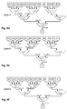
- FIGS. 5 a - 5 f and 6 a - 6 f are applied in FIGS. 8 a - f and 9 a - f to the above described look-ahead implementation.
- FIG. 8 a starts at cycle 0 with the system being in an idle state.
- requests from requester M 2 and M 7 are received at arbiters A 11 and A 12 .
- look-ahead signals are transferred from arbiters A 11 and A 12 to A 21 and from arbiter A 21 to arbiter A 31 .
- the look-ahead signals are transferred to all stages of the hierarchical system at cycle 1 . It is to be noted here that in the figures look-ahead signals (look-ahead requests) are indicated by circles while pipeline requests are indicated by a rhomb.
- the requests from requesters M 2 and M 7 are the only requests active and are therefore granted.
- the requests from requesters M 2 and M 7 are the only requests active and are therefore granted.
- two look-ahead requests from A 11 and A 12 are active. As no other pipeline request is active, the two look-ahead requests are arbitrated and the request at input 1 corresponding to A 11 is granted.
- the look-ahead request from A 21 is the only active request and therefore the first input corresponding to A 21 is granted.
- requests from requesters M 1 , M 6 and M 9 are received at arbiters A 11 , A 12 and A 13 and are granted as no other requests are active at the respective arbiters.
- Look-ahead requests are generated for each requester M 1 , M 6 and M 9 and are provided down the respective branches, i.e. to arbiters A 21 and A 31 for M 1 and M 6 and to arbiters A 22 and A 31 for M 9 .
- arbiter A 21 in cycle 2 three requests are now active. Two look-ahead requests and one pipeline request.
- the pipeline request at arbiter A 21 is a request corresponding to the request of requester M 7 in the previous cycle.
- requests are received from requesters M 4 and M 8 at arbiters A 11 and A 12 , respectively.
- Look-ahead requests are transferred to arbiters A 21 and A 31 .
- Arbiter A 21 has in cycle 3 four requests, two look-ahead requests and 2 pipeline request from A 11 and A 21 , respectively.
- pipeline requests are prioritized, and therefore arbitration is performed between the two pipeline requests and grant is given to the first input.
- Arbiter A 31 has in cycle 3 two pipeline requests from arbiters A 21 and A 22 and one look-ahead request. Arbitration is performed among the pipeline requests and grant is given to the second input. It is to be noted at this point that in cycle 3 an only-pipelined operation is performed as each of the arbiters performing in cycle 3 arbitration is arbitrating among pipeline requests.
- cycle 4 new requests are received at arbiters A 11 , A 12 and A 13 from requesters M 2 , M 7 and M 10 , respectively.
- Look-ahead requests are transferred to arbiters A 21 and A 31 for requests from M 2 and M 7 and look-ahead requests are transferred to arbiters A 22 and A 31 for the request from M 10 .
- the arbiters A 21 and A 31 all have active pipeline requests and therefore the look-ahead requests from M 2 and M 7 will not be taken into account.
- the look-ahead requests based on the request from M 10 allow this request to get granted by arbiters A 13 and A 22 in one cycle.
- the look-ahead request from M 10 at arbiter A 31 is discarded as there is an active pipeline request at input 1 . Since the look-ahead requests from M 10 was granted by arbiters A 13 and A 22 , the request has advanced in one cycle two stages down the pipeline. Thus, the arbiters A 13 and A 22 are performing a parallel operation on the request from M 10 . Comparing to pure pipeline operation, where grant would have been given only from arbiter A 13 for this request within this cycle, the request has “gained” one stage further in the pipeline.
- arbiters A 21 it is to be noted that the pipeline request resulting from the arbitration in the previous cycle (cycle 3 ) could not be transferred to the corresponding input of arbiter A 31 as the request in arbiter A 31 is still active because the input was not granted in the previous cycle.
- Arbiter A 11 which has received a new request from requester M 2 performs normal arbitration and grants this request as indicated in FIG. 8 e.
- arbiters A 11 and A 12 are blocked since arbiter A 21 was blocked in the previous cycle and therefore active pipeline requests at the input of arbiter A 21 could not be removed in the previous cycle to allow new requests to advance. Therefore, the pipeline request maintained at cycle 4 at the output of arbiter A 21 is still not allowed to be transferred to arbiter A 21 . Furthermore, the request from M 2 granted in cycle 4 could not be transferred at the end of cycle 4 to arbiter A 21 as the old request is still pending at input 1 of arbiter A 21 due to the blocking of arbiter A 21 in the previous cycle.
- Arbiter A 21 performs during cycle 5 normal arbitration among the pending pipeline requests and grants input 2 corresponding to A 12 in the arbitration process.
- FIGS. 9 a to 9 f show now the data path system for the above described operation.
- the multiplexer are idle or indefinite since no information of granted inputs are stored in the registers.
- the multiplexer are set according to the stored information in the respective registers (compare for the information stored in the register at the end of the previous cycle, i.e. in cycle 1 shown in FIG. 8 b ) and data transfer is allowed for requester M 2 to be transferred throughout all stages to the shared resource within one cycle.
- data from M 7 can be transferred from requester M 7 to the input of multiplexer D 21 during cycle 2 .
- cycle 3 the multiplexers are switched according to the actual information of each of the registers (see FIG. 8 c ).
- data from M 7 is transferred from the input of multiplexer D 21 to the shared resource during this cycle.
- data form M 1 and data from M 6 is allowed to advance down the pipeline until the respective inputs of multiplexer D 21 during this cycle.
- data from M 9 is transferred during cycle 3 from the requester M 9 to the input of multiplexer D 31 .
- the multiplexer D 31 is switched to input 2 allowing the data from M 9 available at this input to be transferred to the shared resource. Furthermore, data from M 1 advances down the pipeline from the input of multiplexer D 21 to the input of multiplexer D 31 and data from M 4 advances from the requester M 4 to the input of multiplexer D 21 . The data from M 6 is not transferred in this cycle and is still available at the input 2 of multiplexer D 21 .
- the data from M 1 is transferred from the input of D 31 to the shared resource and the data from M 4 is transferred from the input of multiplexer D 21 to the input of multiplexer D 31 .
- data from M 2 is transferred from requester M 2 to the input of multiplexer D 21 .
- the data from M 6 is not transferred.
- data from M 10 is transferred from requester M 10 to the input of multiplexer D 31 . Again it is to be noted here that data from M 10 is transferred more than one stage in the hierarchical system.
- the data from M 4 is transferred from the input from D 31 to the shared source and the data from M 6 is transferred from the input of multiplexer D 21 to the input of multiplexer D 31 . Furthermore data from M 9 are transferred from the requester M 9 to the input of multiplexer D 22 .
- the above described embodiment overcomes therefore dead-times of the pipeline due to idle arbiters by generating look-ahead requests along the corresponding branch of the hierarchical system for each request received from a requester.
- a further modification may according to one embodiment be obtained by providing look-ahead requests for each request from a requester and for each pipeline request. This allows to “bridge gaps” (idle states) of the pipeline in the middle of the pipeline.
- the above operation may according to one embodiment provided by providing a further input to the plurality of inputs 300 c for the OR-component, wherein the further input is connected to the output 300 b as shown in FIG. 10 .
- each of the requester is coupled to an arbiter of the first stage
- other embodiments may be provided where some of the requesters are coupled to an arbiter of a higher stage, for example a second stage or even to the top-level stage.
- inventive subject matter may be referred to herein, individually and/or collectively, by the term “invention” merely for convenience and without intending to voluntarily limit the scope of this application to any single invention or inventive concept if more than one is in fact disclosed.
- inventive concept merely for convenience and without intending to voluntarily limit the scope of this application to any single invention or inventive concept if more than one is in fact disclosed.
- circuit or circuitry
- circuitry or any combinations thereof.
- coupled or “connected” may be interpreted in a broad sense not only covering direct but also indirect coupling.
Abstract
Description
Claims (18)
Priority Applications (2)
| Application Number | Priority Date | Filing Date | Title |
|---|---|---|---|
| US11/842,965 US7734856B2 (en) | 2007-08-22 | 2007-08-22 | Method for operating a plurality of arbiters and arbiter system |
| DE102008034500.8A DE102008034500B4 (en) | 2007-08-22 | 2008-07-24 | arbitration |
Applications Claiming Priority (1)
| Application Number | Priority Date | Filing Date | Title |
|---|---|---|---|
| US11/842,965 US7734856B2 (en) | 2007-08-22 | 2007-08-22 | Method for operating a plurality of arbiters and arbiter system |
Publications (2)
| Publication Number | Publication Date |
|---|---|
| US20090055566A1 US20090055566A1 (en) | 2009-02-26 |
| US7734856B2 true US7734856B2 (en) | 2010-06-08 |
Family
ID=40280371
Family Applications (1)
| Application Number | Title | Priority Date | Filing Date |
|---|---|---|---|
| US11/842,965 Active 2028-04-27 US7734856B2 (en) | 2007-08-22 | 2007-08-22 | Method for operating a plurality of arbiters and arbiter system |
Country Status (2)
| Country | Link |
|---|---|
| US (1) | US7734856B2 (en) |
| DE (1) | DE102008034500B4 (en) |
Cited By (14)
| Publication number | Priority date | Publication date | Assignee | Title |
|---|---|---|---|---|
| US20110238877A1 (en) * | 2008-11-28 | 2011-09-29 | Telefonaktiebolaget Lm Ericsson (Publ) | Arbitration in Multiprocessor Device |
| US8270335B1 (en) * | 2008-02-28 | 2012-09-18 | Xilinx, Inc. | Arbitration for time division multiple access using delta sigma modulation |
| WO2013032715A1 (en) * | 2011-08-31 | 2013-03-07 | Intel Corporation | Providing adaptive bandwidth allocation for a fixed priority arbiter |
| US8711875B2 (en) | 2011-09-29 | 2014-04-29 | Intel Corporation | Aggregating completion messages in a sideband interface |
| US8713240B2 (en) | 2011-09-29 | 2014-04-29 | Intel Corporation | Providing multiple decode options for a system-on-chip (SoC) fabric |
| US8713234B2 (en) | 2011-09-29 | 2014-04-29 | Intel Corporation | Supporting multiple channels of a single interface |
| US8775700B2 (en) | 2011-09-29 | 2014-07-08 | Intel Corporation | Issuing requests to a fabric |
| US8805926B2 (en) | 2011-09-29 | 2014-08-12 | Intel Corporation | Common idle state, active state and credit management for an interface |
| US8874976B2 (en) | 2011-09-29 | 2014-10-28 | Intel Corporation | Providing error handling support to legacy devices |
| US8929373B2 (en) | 2011-09-29 | 2015-01-06 | Intel Corporation | Sending packets with expanded headers |
| US9021156B2 (en) | 2011-08-31 | 2015-04-28 | Prashanth Nimmala | Integrating intellectual property (IP) blocks into a processor |
| US9053251B2 (en) | 2011-11-29 | 2015-06-09 | Intel Corporation | Providing a sideband message interface for system on a chip (SoC) |
| US10846126B2 (en) | 2016-12-28 | 2020-11-24 | Intel Corporation | Method, apparatus and system for handling non-posted memory write transactions in a fabric |
| US10911261B2 (en) | 2016-12-19 | 2021-02-02 | Intel Corporation | Method, apparatus and system for hierarchical network on chip routing |
Families Citing this family (17)
| Publication number | Priority date | Publication date | Assignee | Title |
|---|---|---|---|---|
| US8595394B1 (en) * | 2003-06-26 | 2013-11-26 | Nvidia Corporation | Method and system for dynamic buffering of disk I/O command chains |
| US8683132B1 (en) | 2003-09-29 | 2014-03-25 | Nvidia Corporation | Memory controller for sequentially prefetching data for a processor of a computer system |
| US8356142B1 (en) | 2003-11-12 | 2013-01-15 | Nvidia Corporation | Memory controller for non-sequentially prefetching data for a processor of a computer system |
| US8700808B2 (en) * | 2003-12-01 | 2014-04-15 | Nvidia Corporation | Hardware support system for accelerated disk I/O |
| US8356143B1 (en) | 2004-10-22 | 2013-01-15 | NVIDIA Corporatin | Prefetch mechanism for bus master memory access |
| US8356128B2 (en) * | 2008-09-16 | 2013-01-15 | Nvidia Corporation | Method and system of reducing latencies associated with resource allocation by using multiple arbiters |
| US8370552B2 (en) | 2008-10-14 | 2013-02-05 | Nvidia Corporation | Priority based bus arbiters avoiding deadlock and starvation on buses that support retrying of transactions |
| US8698823B2 (en) | 2009-04-08 | 2014-04-15 | Nvidia Corporation | System and method for deadlock-free pipelining |
| US8904115B2 (en) * | 2010-09-28 | 2014-12-02 | Texas Instruments Incorporated | Cache with multiple access pipelines |
| US9569385B2 (en) | 2013-09-09 | 2017-02-14 | Nvidia Corporation | Memory transaction ordering |
| GB2528071B (en) * | 2014-07-08 | 2021-04-07 | Advanced Risc Mach Ltd | Arbitrating and multiplexing circuitry |
| JP6481427B2 (en) * | 2015-03-10 | 2019-03-13 | 富士通株式会社 | Arithmetic processing device, information processing device, and control method for information processing device |
| US10684969B2 (en) * | 2016-07-15 | 2020-06-16 | Advanced Micro Devices, Inc. | Command arbitration for high speed memory interfaces |
| EP3270294B1 (en) * | 2016-07-15 | 2018-09-26 | Advanced Micro Devices, Inc. | Command arbitration for high-speed memory interfaces |
| CN110729006B (en) | 2018-07-16 | 2022-07-05 | 超威半导体(上海)有限公司 | Refresh scheme in a memory controller |
| JP7401050B2 (en) * | 2018-09-18 | 2023-12-19 | キヤノン株式会社 | bus control circuit |
| KR20210103836A (en) * | 2020-02-14 | 2021-08-24 | 에스케이하이닉스 주식회사 | Data Processing Apparatus and Operation Method Thereof |
Citations (18)
| Publication number | Priority date | Publication date | Assignee | Title |
|---|---|---|---|---|
| US5280591A (en) | 1991-07-22 | 1994-01-18 | International Business Machines, Corporation | Centralized backplane bus arbiter for multiprocessor systems |
| US5301333A (en) | 1990-06-14 | 1994-04-05 | Bell Communications Research, Inc. | Tree structured variable priority arbitration implementing a round-robin scheduling policy |
| US6032218A (en) | 1998-05-28 | 2000-02-29 | 3Com Corporation | Configurable weighted round robin arbiter |
| US6148002A (en) | 1996-12-30 | 2000-11-14 | 3Com Corporation | Shared auto-negotiation logic for multiple port network devices |
| US6311249B1 (en) * | 1997-03-12 | 2001-10-30 | Hyundai Electronics Industries Co., Ltd. | Bus arbitration system having both round robin and daisy chain arbiters |
| US6338121B1 (en) * | 1999-05-20 | 2002-01-08 | International Business Machines Corporation | Data source arbitration in a multiprocessor system |
| US6487213B1 (en) | 1998-01-05 | 2002-11-26 | Polytechnic University | Methods and apparatus for fairly arbitrating contention for an output port |
| JP2003256358A (en) | 2002-02-28 | 2003-09-12 | Sony Corp | Arbiter apparatus and method therefor as well as resource sharing system |
| US20030223453A1 (en) | 2002-05-31 | 2003-12-04 | Gil Stoler | Round-robin arbiter with low jitter |
| US20040103231A1 (en) * | 2002-11-22 | 2004-05-27 | Divio, Inc. | Hierarchical bus arbitration |
| US20040133724A1 (en) | 2002-11-27 | 2004-07-08 | Samsung Electronics Co., Ltd | Programmable fixed priority and round robin arbiter for providing high-speed arbitration and bus control method therein |
| US6763418B1 (en) | 2001-09-07 | 2004-07-13 | Agilent Technologies, Inc. | Request bus arbitration |
| US20040210696A1 (en) * | 2003-04-18 | 2004-10-21 | Meyer Michael J. | Method and apparatus for round robin resource arbitration |
| US20040250003A1 (en) | 2003-06-04 | 2004-12-09 | Christopher Chang | Bus bandwidth control system |
| US6954812B2 (en) * | 2002-03-05 | 2005-10-11 | Hewlett-Packard Development Company, L.P. | Two-stage round robin arbitration system |
| US20060236010A1 (en) * | 2003-05-27 | 2006-10-19 | Intel Corporation | High-speed starvation-free arbiter system, rotating-priority arbiter, and two-stage arbitration method |
| US7143219B1 (en) * | 2002-12-31 | 2006-11-28 | Intel Corporation | Multilevel fair priority round robin arbiter |
| US20090006693A1 (en) * | 2007-06-27 | 2009-01-01 | International Business Machiness Corporation | Apparatus and Method for Fairness Arbitration for a Shared Pipeline in a Large SMP Computer System |
-
2007
- 2007-08-22 US US11/842,965 patent/US7734856B2/en active Active
-
2008
- 2008-07-24 DE DE102008034500.8A patent/DE102008034500B4/en active Active
Patent Citations (18)
| Publication number | Priority date | Publication date | Assignee | Title |
|---|---|---|---|---|
| US5301333A (en) | 1990-06-14 | 1994-04-05 | Bell Communications Research, Inc. | Tree structured variable priority arbitration implementing a round-robin scheduling policy |
| US5280591A (en) | 1991-07-22 | 1994-01-18 | International Business Machines, Corporation | Centralized backplane bus arbiter for multiprocessor systems |
| US6148002A (en) | 1996-12-30 | 2000-11-14 | 3Com Corporation | Shared auto-negotiation logic for multiple port network devices |
| US6311249B1 (en) * | 1997-03-12 | 2001-10-30 | Hyundai Electronics Industries Co., Ltd. | Bus arbitration system having both round robin and daisy chain arbiters |
| US6487213B1 (en) | 1998-01-05 | 2002-11-26 | Polytechnic University | Methods and apparatus for fairly arbitrating contention for an output port |
| US6032218A (en) | 1998-05-28 | 2000-02-29 | 3Com Corporation | Configurable weighted round robin arbiter |
| US6338121B1 (en) * | 1999-05-20 | 2002-01-08 | International Business Machines Corporation | Data source arbitration in a multiprocessor system |
| US6763418B1 (en) | 2001-09-07 | 2004-07-13 | Agilent Technologies, Inc. | Request bus arbitration |
| JP2003256358A (en) | 2002-02-28 | 2003-09-12 | Sony Corp | Arbiter apparatus and method therefor as well as resource sharing system |
| US6954812B2 (en) * | 2002-03-05 | 2005-10-11 | Hewlett-Packard Development Company, L.P. | Two-stage round robin arbitration system |
| US20030223453A1 (en) | 2002-05-31 | 2003-12-04 | Gil Stoler | Round-robin arbiter with low jitter |
| US20040103231A1 (en) * | 2002-11-22 | 2004-05-27 | Divio, Inc. | Hierarchical bus arbitration |
| US20040133724A1 (en) | 2002-11-27 | 2004-07-08 | Samsung Electronics Co., Ltd | Programmable fixed priority and round robin arbiter for providing high-speed arbitration and bus control method therein |
| US7143219B1 (en) * | 2002-12-31 | 2006-11-28 | Intel Corporation | Multilevel fair priority round robin arbiter |
| US20040210696A1 (en) * | 2003-04-18 | 2004-10-21 | Meyer Michael J. | Method and apparatus for round robin resource arbitration |
| US20060236010A1 (en) * | 2003-05-27 | 2006-10-19 | Intel Corporation | High-speed starvation-free arbiter system, rotating-priority arbiter, and two-stage arbitration method |
| US20040250003A1 (en) | 2003-06-04 | 2004-12-09 | Christopher Chang | Bus bandwidth control system |
| US20090006693A1 (en) * | 2007-06-27 | 2009-01-01 | International Business Machiness Corporation | Apparatus and Method for Fairness Arbitration for a Shared Pipeline in a Large SMP Computer System |
Non-Patent Citations (3)
| Title |
|---|
| Dr. phil. Georg Pflug, 3.1.2.1. Die Round-Robin (Rr-) Regel, Stochastische Modelle in der Informatik, 1986, pp. No. 102-104, B. G. Teubner, Stuttgart, DE. |
| Francis Cottet et.al.:, 1.2.2 Scheduling: definitions, algorithms and properties (pages No. 13-17) and 1.2.3 Scheduling in classical operating systems (pages No. 17-19), Scheduling in Real-Time Systems, 2002, John Wiley & Sons Ltd., West Sussex, GB. |
| John L. Hennessy and David A. Patterson, 7.3 Buses-Connecting I/O Devices to CPU/Memory, Computer Architecture A Quantitative Apporach, Published 1990. Third edition 2003, pages No. 692-702, Morgan Kaufmann Publishers, San Francisco, CA (US). |
Cited By (21)
| Publication number | Priority date | Publication date | Assignee | Title |
|---|---|---|---|---|
| US8270335B1 (en) * | 2008-02-28 | 2012-09-18 | Xilinx, Inc. | Arbitration for time division multiple access using delta sigma modulation |
| US8688881B2 (en) * | 2008-11-28 | 2014-04-01 | Telefonaktiebolaget L M Ericsson (Publ) | Arbitration in multiprocessor device |
| US20110238877A1 (en) * | 2008-11-28 | 2011-09-29 | Telefonaktiebolaget Lm Ericsson (Publ) | Arbitration in Multiprocessor Device |
| US8930602B2 (en) | 2011-08-31 | 2015-01-06 | Intel Corporation | Providing adaptive bandwidth allocation for a fixed priority arbiter |
| WO2013032715A1 (en) * | 2011-08-31 | 2013-03-07 | Intel Corporation | Providing adaptive bandwidth allocation for a fixed priority arbiter |
| US9021156B2 (en) | 2011-08-31 | 2015-04-28 | Prashanth Nimmala | Integrating intellectual property (IP) blocks into a processor |
| US8713240B2 (en) | 2011-09-29 | 2014-04-29 | Intel Corporation | Providing multiple decode options for a system-on-chip (SoC) fabric |
| US9658978B2 (en) | 2011-09-29 | 2017-05-23 | Intel Corporation | Providing multiple decode options for a system-on-chip (SoC) fabric |
| US8805926B2 (en) | 2011-09-29 | 2014-08-12 | Intel Corporation | Common idle state, active state and credit management for an interface |
| US8874976B2 (en) | 2011-09-29 | 2014-10-28 | Intel Corporation | Providing error handling support to legacy devices |
| US8713234B2 (en) | 2011-09-29 | 2014-04-29 | Intel Corporation | Supporting multiple channels of a single interface |
| US8929373B2 (en) | 2011-09-29 | 2015-01-06 | Intel Corporation | Sending packets with expanded headers |
| US8711875B2 (en) | 2011-09-29 | 2014-04-29 | Intel Corporation | Aggregating completion messages in a sideband interface |
| US10164880B2 (en) | 2011-09-29 | 2018-12-25 | Intel Corporation | Sending packets with expanded headers |
| US8775700B2 (en) | 2011-09-29 | 2014-07-08 | Intel Corporation | Issuing requests to a fabric |
| US9448870B2 (en) | 2011-09-29 | 2016-09-20 | Intel Corporation | Providing error handling support to legacy devices |
| US9213666B2 (en) | 2011-11-29 | 2015-12-15 | Intel Corporation | Providing a sideband message interface for system on a chip (SoC) |
| US9053251B2 (en) | 2011-11-29 | 2015-06-09 | Intel Corporation | Providing a sideband message interface for system on a chip (SoC) |
| US10911261B2 (en) | 2016-12-19 | 2021-02-02 | Intel Corporation | Method, apparatus and system for hierarchical network on chip routing |
| US10846126B2 (en) | 2016-12-28 | 2020-11-24 | Intel Corporation | Method, apparatus and system for handling non-posted memory write transactions in a fabric |
| US11372674B2 (en) | 2016-12-28 | 2022-06-28 | Intel Corporation | Method, apparatus and system for handling non-posted memory write transactions in a fabric |
Also Published As
| Publication number | Publication date |
|---|---|
| DE102008034500B4 (en) | 2014-10-02 |
| DE102008034500A1 (en) | 2009-02-26 |
| US20090055566A1 (en) | 2009-02-26 |
Similar Documents
| Publication | Publication Date | Title |
|---|---|---|
| US7734856B2 (en) | Method for operating a plurality of arbiters and arbiter system | |
| US8452907B2 (en) | Data processing apparatus and method for arbitrating access to a shared resource | |
| EP1403773B1 (en) | Resource management device | |
| US7673087B1 (en) | Arbitration for an embedded processor block core in an integrated circuit | |
| JPH0210979B2 (en) | ||
| US20080082707A1 (en) | Non-blocking bus controller for a pipelined, variable latency, hierarchical bus with point-to-point first-in first-out ordering | |
| KR100252752B1 (en) | Multi stage control bus arbitration apparatus | |
| US8688881B2 (en) | Arbitration in multiprocessor device | |
| JP2009508247A (en) | Method and system for bus arbitration | |
| US20060282588A1 (en) | Processor system that allows for simultaneous access by multiple requestors to a target with multiple ports | |
| JP2010282405A (en) | Data processing system | |
| EP1164493B1 (en) | Variable priority arbitration method, for instance for interconnect buses, and respective system | |
| US7664901B2 (en) | Data processing apparatus and method for arbitrating access to a shared resource | |
| US7512729B2 (en) | Method and apparatus for a high efficiency two-stage rotating priority arbiter with predictable arbitration latency | |
| EP1439467B1 (en) | System and method for allocating a plurality of sources to a plurality of channels | |
| EP2442231A1 (en) | Reordering arrangement | |
| US7395360B1 (en) | Programmable chip bus arbitration logic | |
| WO2016203240A1 (en) | Integrated circuit inputs and outputs | |
| US7487276B2 (en) | Bus arbitration system | |
| KR100486247B1 (en) | Apparatus and method for controlling | |
| US20080235707A1 (en) | Data processing apparatus and method for performing multi-cycle arbitration | |
| US10838892B1 (en) | Multistage round robin arbitration | |
| EP1207457A1 (en) | External bus arbitration technique for multicore DSP device | |
| US7930456B1 (en) | Data packet arbitration system | |
| US10949258B1 (en) | Multistage round robin arbitration in a multiuser system |
Legal Events
| Date | Code | Title | Description |
|---|---|---|---|
| AS | Assignment |
Owner name: INFINEON TECHNOLOGIES AG, GERMANY Free format text: ASSIGNMENT OF ASSIGNORS INTEREST;ASSIGNORS:REINIG, HELMUT;SONNTAG, SOEREN;REEL/FRAME:019928/0618;SIGNING DATES FROM 20070802 TO 20070810 Owner name: INFINEON TECHNOLOGIES AG,GERMANY Free format text: ASSIGNMENT OF ASSIGNORS INTEREST;ASSIGNORS:REINIG, HELMUT;SONNTAG, SOEREN;SIGNING DATES FROM 20070802 TO 20070810;REEL/FRAME:019928/0618 |
|
| FEPP | Fee payment procedure |
Free format text: PAYOR NUMBER ASSIGNED (ORIGINAL EVENT CODE: ASPN); ENTITY STATUS OF PATENT OWNER: LARGE ENTITY |
|
| STCF | Information on status: patent grant |
Free format text: PATENTED CASE |
|
| AS | Assignment |
Owner name: INFINEON TECHNOLOGIES WIRELESS SOLUTIONS GMBH,GERM Free format text: ASSIGNMENT OF ASSIGNORS INTEREST;ASSIGNOR:INFINEON TECHNOLOGIES AG;REEL/FRAME:024483/0001 Effective date: 20090703 Owner name: INFINEON TECHNOLOGIES WIRELESS SOLUTIONS GMBH, GER Free format text: ASSIGNMENT OF ASSIGNORS INTEREST;ASSIGNOR:INFINEON TECHNOLOGIES AG;REEL/FRAME:024483/0001 Effective date: 20090703 |
|
| AS | Assignment |
Owner name: LANTIQ DEUTSCHLAND GMBH,GERMANY Free format text: ASSIGNMENT OF ASSIGNORS INTEREST;ASSIGNOR:INFINEON TECHNOLOGIES WIRELESS SOLUTIONS GMBH;REEL/FRAME:024529/0656 Effective date: 20091106 Owner name: LANTIQ DEUTSCHLAND GMBH, GERMANY Free format text: ASSIGNMENT OF ASSIGNORS INTEREST;ASSIGNOR:INFINEON TECHNOLOGIES WIRELESS SOLUTIONS GMBH;REEL/FRAME:024529/0656 Effective date: 20091106 |
|
| AS | Assignment |
Owner name: DEUTSCHE BANK AG NEW YORK BRANCH, AS COLLATERAL AG Free format text: GRANT OF SECURITY INTEREST IN U.S. PATENTS;ASSIGNOR:LANTIQ DEUTSCHLAND GMBH;REEL/FRAME:025406/0677 Effective date: 20101116 |
|
| FPAY | Fee payment |
Year of fee payment: 4 |
|
| AS | Assignment |
Owner name: LANTIQ BETEILIGUNGS-GMBH & CO. KG, GERMANY Free format text: RELEASE OF SECURITY INTEREST RECORDED AT REEL/FRAME 025413/0340 AND 025406/0677;ASSIGNOR:DEUTSCHE BANK AG NEW YORK BRANCH, AS COLLATERAL AGENT;REEL/FRAME:035453/0712 Effective date: 20150415 |
|
| MAFP | Maintenance fee payment |
Free format text: PAYMENT OF MAINTENANCE FEE, 8TH YEAR, LARGE ENTITY (ORIGINAL EVENT CODE: M1552) Year of fee payment: 8 |
|
| AS | Assignment |
Owner name: LANTIQ BETEILIGUNGS-GMBH & CO. KG, GERMANY Free format text: MERGER;ASSIGNOR:LANTIQ DEUTSCHLAND GMBH;REEL/FRAME:044907/0045 Effective date: 20150303 |
|
| AS | Assignment |
Owner name: LANTIQ BETEILIGUNGS-GMBH & CO. KG, GERMANY Free format text: MERGER AND CHANGE OF NAME;ASSIGNORS:LANTIQ DEUTSCHLAND GMBH;LANTIQ BETEILIGUNGS-GMBH & CO. KG;REEL/FRAME:045085/0292 Effective date: 20150303 |
|
| AS | Assignment |
Owner name: INTEL CORPORATION, CALIFORNIA Free format text: ASSIGNMENT OF ASSIGNORS INTEREST;ASSIGNOR:LANTIQ BETEILIGUNGS-GMBH & CO. KG;REEL/FRAME:053259/0678 Effective date: 20200710 |
|
| AS | Assignment |
Owner name: MAXLINEAR, INC., CALIFORNIA Free format text: ASSIGNMENT OF ASSIGNORS INTEREST;ASSIGNOR:INTEL CORPORATION;REEL/FRAME:053626/0636 Effective date: 20200731 |
|
| AS | Assignment |
Owner name: WELLS FARGO BANK, NATIONAL ASSOCIATION, COLORADO Free format text: SECURITY AGREEMENT;ASSIGNORS:MAXLINEAR, INC.;MAXLINEAR COMMUNICATIONS, LLC;EXAR CORPORATION;REEL/FRAME:056816/0089 Effective date: 20210708 |
|
| MAFP | Maintenance fee payment |
Free format text: PAYMENT OF MAINTENANCE FEE, 12TH YEAR, LARGE ENTITY (ORIGINAL EVENT CODE: M1553); ENTITY STATUS OF PATENT OWNER: LARGE ENTITY Year of fee payment: 12 |