US7741994B2 - Ionospheric error prediction and correction in satellite positioning systems - Google Patents
Ionospheric error prediction and correction in satellite positioning systems Download PDFInfo
- Publication number
- US7741994B2 US7741994B2 US10/504,233 US50423305A US7741994B2 US 7741994 B2 US7741994 B2 US 7741994B2 US 50423305 A US50423305 A US 50423305A US 7741994 B2 US7741994 B2 US 7741994B2
- Authority
- US
- United States
- Prior art keywords
- sps
- ionospheric
- server
- mobile
- errors
- Prior art date
- Legal status (The legal status is an assumption and is not a legal conclusion. Google has not performed a legal analysis and makes no representation as to the accuracy of the status listed.)
- Expired - Lifetime
Links
Images


Classifications
-
- G—PHYSICS
- G01—MEASURING; TESTING
- G01S—RADIO DIRECTION-FINDING; RADIO NAVIGATION; DETERMINING DISTANCE OR VELOCITY BY USE OF RADIO WAVES; LOCATING OR PRESENCE-DETECTING BY USE OF THE REFLECTION OR RERADIATION OF RADIO WAVES; ANALOGOUS ARRANGEMENTS USING OTHER WAVES
- G01S19/00—Satellite radio beacon positioning systems; Determining position, velocity or attitude using signals transmitted by such systems
- G01S19/01—Satellite radio beacon positioning systems transmitting time-stamped messages, e.g. GPS [Global Positioning System], GLONASS [Global Orbiting Navigation Satellite System] or GALILEO
- G01S19/03—Cooperating elements; Interaction or communication between different cooperating elements or between cooperating elements and receivers
- G01S19/07—Cooperating elements; Interaction or communication between different cooperating elements or between cooperating elements and receivers providing data for correcting measured positioning data, e.g. DGPS [differential GPS] or ionosphere corrections
- G01S19/072—Ionosphere corrections
Definitions
- This invention relates generally to satellite positioning systems (“SPS”) devices, and in particular to ionospheric error predication and correction in an SPS.
- SPS satellite positioning systems
- Satellite positioning systems are satellite-based navigation systems.
- SPS include but are not limited to the United States (“U.S.”) Navy Navigation Satellite System (“NNSS”) (also know as TRANSIT), LORAN, Shoran, Decca, TACAN, the Joint Program Office (“JPO”) Global Positioning System (“GPS”) (also known as NAVSTAR, which was developed by the U.S. Department of Defense (“DoD”) in the early 1970s), the Russian counterpart known as Global Navigation Satellite System (“GLONASS”) and any future Western European SPS such the proposed “Galileo” program.
- the NAVSTAR GPS was originally developed as a military system to fulfill the needs of the U.S. military; however, the U.S.
- GPS is now a dual-use system that may be accessed by both U.S. government agencies (such as the military) and civilians.
- the GPS system is described in GPS Theory and Practice , Fifth ed., revised edition by Hofiann-Wellenhof, Lichtenegger and Collins, Springer-Verlag Wien NewYork, 2001, which is fully incorporated herein by reference.
- SPS typically includes identifying precise locations on the Earth and synchronizing telecommunication networks such as military communication networks and the code division multiple access (“CDMA”) cellular telephone networks.
- CDMA code division multiple access
- FCC Federal Communications Commission
- SPS will be employed for both location determination and synchronization in many cellular applications.
- the array of GPS satellites transmit highly accurate, time coded information that permits a GPS receiver to calculate its location in terms of latitude and longitude on Earth as well as the altitude above sea level.
- GPS is designed to provide a base navigation system with accuracy within approximately 100 meters for non-military users and even greater precision for the military and other authorized users (with Selective Availability set to ON).
- the space segment of GPS is a constellation of satellites orbiting above the earth that contain transmitters, which send highly accurate timing information to GPS receivers on earth.
- the implemented GPS constellation includes 21 main operational satellites plus three active spare satellites. These satellites are arranged in six orbits, each orbit containing three or four satellites.
- the orbital planes form a 55° angle with the equator.
- the satellites orbit at a height of approximately 10,898 nautical miles (20,200 kilometers) above the Earth with orbital periods for each satellite of approximately 12 hours.
- each of the orbiting satellites contains four highly accurate atomic clocks (two rubidium and two cesium). These atomic clocks provide precision timing pulses used to generate a unique binary code (also known as a pseudorandom “PRN-code” or pseudo noise “PN-code”) that is transmitted to Earth.
- PRN-code identifies the specific satellite in the constellation.
- the satellite also transmits a set of digitally coded ephemeris data (also known as “ephemerides”) that defines the precise orbit of the satellite.
- the ephemeris data indicates where the satellite is at any given time, and its location may be specified in terms of the satellite ground track in precise latitude and longitude measurements.
- the information in the ephemeris data is coded and transmitted from the satellite providing an accurate indication of the position of the satellite above the Earth at any given time.
- a ground control station updates the ephemeris data of the satellite once per day to ensure accuracy.
- each GPS satellite transmits a microwave radio signal presently composed of two carrier frequencies modulated by two digital codes and a navigation message.
- the two carrier frequencies are generated from a highly accurate fundamental L-band frequency of 10.23 MHz produced by the four atomic clocks.
- the two carrier frequencies known as L 1 and L 2 , are coherently derived from the fundamental frequency by multiplying the fundamental frequency by 154 and 120 to produce L 1 at 1575.42 MHz and L 2 at 1227.60 MHz, respectively. These dual frequencies are utilized to eliminate some of the major sources of error.
- the pseudoranges that are derived from measured travel times of the signal from each satellite to the receiver use two PRN-codes that are modulated onto the two base carriers.
- the first code is the Coarse/Acquisition code (“C/A-code” also known as the “Standard Positioning Service”) that is available for civilian use.
- the C/A-code has an effective wavelength of approximately 300 meters.
- the C/A-code is modulated only on L 1 and is purposely omitted from L 2 . This omission allows DoD to control the information broadcast by the satellite and, thus, denies full system accuracy to non-authorized users.
- the second code is the Precision code (“P-code” also known as the “Precise Positioning Service”) that has been reserved for the U.S. military and other authorized users and has an effective wavelength of approximately 30 meters.
- the P-code is modulated on both the L 1 and L 2 carriers.
- a data message is modulated onto both carriers that include status information, satellite clock bias, and satellite ephemerides. It is appreciated by those skilled in the art that the U.S. intents to improve the above described signal structures in the future.
- DoD has included a number of techniques for denying non-authorized users full access to GPS. These techniques include Selective Availability (“SA”), Anti-spoofing (“A-S”) and Selective Denial (“SD”).
- SA Selective Availability
- A-S Anti-spoofing
- SD Selective Denial
- the goal of SA was to deny navigation accuracy to potential adversaries by dithering the satellite clock and manipulating the ephemerides.
- SA was eventually turned OFF on May 2, 2000.
- A-S has the ability to essentially turn-off the P-code or invoke an encrypted code as a means of denying access to the P-code to all but authorized users.
- A-S is accomplished by the modulo-2 sum of the P-code and an encrypted W-code.
- the resulting code is denoted as the Y-code and when A-S is active the P-code on the L 1 and L 2 carrier is replaced by the unknown Y-code.
- Future plans for signal structure will include a C/A-code on both the L 1 and L 2 carriers and the Y-code will be replaced with a new military split-spectrum signal denoted as the M-code.
- SD denies access to the GPS signal to unauthorized users in regions of interest by utilizing ground-based jammers.
- FIG. 1 illustrates a diagram 100 of an example implementation of an SPS.
- a SPS receiver 102 located on the Earth 104 is designed to pick up signals 106 , 108 , 110 and 112 from several SPS satellites 114 , 116 , 118 and 120 simultaneously.
- the SPS receiver 102 decodes the information and, utilizing the time and ephemeris data, calculates the position of the SPS receiver 102 on the Earth 104 .
- the SPS receiver 102 usually includes a floating-point processor (not shown) that performs the necessary calculations and may output a decimal display of latitude and longitude as well as altitude on a handset (not shown).
- signals 106 , 108 and 110 from at least three satellites 114 , 116 and 118 are needed for latitude and longitude information.
- a fourth satellite 120 signal 112 is needed to compute altitude.
- SPS includes several types of errors that typically degrade the performance of the SPS receiver. These errors include random errors and systematic errors that may originate at the satellites, the SPS receiver or be the result of signal propagation errors.
- the errors originating at the satellites include ephemeris, orbital, satellite clock, and in the case of GPS, the systematic error caused by the SA, S-A and/or SD selections.
- the errors originating at the receiver include; receiver clock errors, multipath error, receiver noise, and antenna phase center variations.
- multipath error correction methods are well known and have been implemented in some GPS chip set architectures.
- the signal propagation errors are the result of atmospheric refraction that includes delays of the SPS signal as it passes through the ionospheric and tropospheric layers of the atmosphere.
- the ionosphere is a dispersive medium, which lies between seventy and one thousand kilometers above the Earth's surface.
- the ionosphere is at the upper part of the atmosphere where the ultraviolet and X-ray radiation from the sun interacts with the gas molecules and atoms of the atmosphere to produce gas ionization.
- the gas ionization results in a large number of free negatively charged electrons and positively charged atoms and molecules.
- the electron density within the ionosphere is not constant and changes with altitude and time as a result of the sun's radiation and the Earth's magnetic field.
- the ionosphere bends SPS radio signals and changes their propagation speed as they passes through the ionosphere. Bending is known to typically cause negligible range errors (particularly if the satellite elevation angle is greater than 5 degrees); however, the change in propagation speed is known to cause significant range errors because the ionosphere speeds up the propagation of the carrier phase beyond the speed of light while slowing down the PRN-code by the same amount.
- the ionospheric delay is proportional to the number of free electrons along the SPS signal path and is known as the Total Electron Content (“TEC”). TEC depends on a number of factors including the time of day, the time of year, the 11-year solar cycle and geographic location of the SPS receiver relative to the SPS satellite.
- the ionosphere causes a delay that is frequency dependent such that the lower the frequency, the greater the delay.
- the L 2 delay is greater than the L 1 delay.
- the ionospheric delay of a transmitted SPS signal may cause an error of approximately ten meters when calculating the position of the SPS receiver.
- DGPS Differential Global Position Systems
- GPS server The stationary SPS receiver is usually known as a “GPS server” and is typically located at a reference site that has known coordinates. If the GPS server and mobile GPS receiver are located within an acceptable proximity of each other, the GPS server and mobile GPS receiver will receive the GPS satellite signals simultaneously. Therefore, most of the errors in the GPS satellite signals will be received equally by both the GPS server and mobile GPS receiver.
- the GPS server calculates any needed error corrections by comparing the difference between its calculated coordinates from the received GPS satellite signal and its known coordinates. These calculated error corrections are transmitted to the mobile GPS receiver, which may then compensate for the received errors in its received GPS satellite signal.
- DGPS is not always available and even when it is it may still take a relatively long time to determine an acceptable position accuracy at the mobile SPS receiver because the mobile SPS receiver needs to receive the differential data from the SPS server.
- this differential data is only the error information observed at the SPS server not the mobile SPS receiver. As the distance between the mobile SPS receiver and SPS server increases, the error information observed at the SPS server becomes less useful.
- ionospheric error includes using models of the ionosphere to predict the ionospheric errors.
- the model approach is most often utilized in non-DGPS standalone GPS applications.
- the Klobuchar model also known as the TEC model
- ICD-GPS-200 Revision C, Initial Release, Oct. 10, 1993, which is fully incorporated herein by reference.
- the ionospheric error may be modeled as a shell (also known as a “half-cosine” curve) that is described by the following physical relationship
- T iono ⁇ F ⁇ [ DC + A ⁇ cos ⁇ ( 2 ⁇ ⁇ ⁇ ( t - ⁇ ) P ) ] , if ⁇
- ⁇ ⁇ x 2 ⁇ ⁇ ⁇ ( t - ⁇ ) / P ⁇ ⁇
- ⁇ ⁇ T iono also known as T zenith
- FIG. 2 illustrates an example graph 200 of T zenith 202 in nanoseconds versus local time 204 in hours.
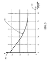
- FIG. 3 illustrates an example graph 300 of F 302 versus elevation angle 304 in degrees.
- the second part of the T iono formula represents the error effect caused by the change to the TEC.
- Reference paragraph 20.3.3.5.1.9 defines parameters that allow the L 1 only, or L 2 only, user to utilize the ionospheric model (reference paragraph 20.3.3.5.2.5) for computation of the ionospheric delay and are contained in page 18 of subframe 4.
- the bit lengths, scale factors, ranges and units of these parameters are given in Table 20-X of the ICD-GPS-200.
- ICD-GPS-200 treats both DC and ⁇ as constant values while the actual TEC values of the ionosphere is difficult to model.
- DC has a constant value of 5 nanoseconds though it is known to vary from location to location and the phase term ⁇ has a constant value of 14 hours (i.e., 50,400 seconds) although it is also known to vary from 11 to 17 hours for a certain season, location and condition of solar activity.
- the ICD-GPS-200 model is known to correct for no more than about 50% of the ionospheric transmission delays.
- This invention provides a way for satellite positioning systems (“SPS”) to more accurately determine a SPS receiver's position with less frequent message transmission compared to conventional way of SPS receivers.
- SPS satellite positioning systems
- a SPS system having a GPS receiver and a GPS server compensates for ionospheric errors by receiving ionospheric information at periodic times coinciding with ionospheric events such as sunrise, noon and sun set. The compensation information is sent to a GPS receiver at predetermined events, such as power up, sunrise, noon, and sun set. The GPS receiver then may use other error correction methods in addition to ionospheric error correction when determining the position of the GPS receiver.
- FIG. 1 illustrates a block diagram of an example implementation of a satellite positioning system (“SPS”).
- SPS satellite positioning system
- FIG. 2 illustrates an example graph of T zenith in nanoseconds versus local time in hours.
- FIG. 3 illustrates an example graph of F versus elevation angle in degrees.
- FIG. 4 is block diagram of an example implementation of a SPS for predicting and compensating for ionospheric errors (“SPSPC”).
- SPSPC ionospheric errors
- FIG. 5 is a block diagram of an example implementation of the Server Position Calculation Module shown in FIG. 4 .
- FIG. 6 is a block diagram of another example implementation of the Server Position Calculation Module shown in FIG. 4 .
- FIG. 7 is a block diagram of an example implementation of the Mobile Position Calculation Module shown in FIG. 4 .
- FIG. 8 is a flowchart diagram illustrating an example process preformed by the SPS Server shown in FIG. 4 in determining the ionospheric error correction.
- FIG. 9 is a flowchart diagram illustrating an example process preformed by the mobile SPS receiver shown in FIG. 4 in compensating for ionospheric error.
- a satellite positioning system (“SPS”) for predicting and compensating for ionospheric errors (“SPSPC”) 400 is shown having a SPS server 402 and a mobile SPS receiver 404 .
- SPS server 402 and mobile SPS receiver 404 are in signal communication with various SPS satellites 406 , 408 and 410 via signal paths 412 , 414 , 416 , 418 , 420 and 422 , respectively.
- the SPS server 402 is in signal communication with the mobile SPS receiver 404 via signal path 424 .
- the SPS server 402 may include a server radio frequency (“RF”) front-end. 426 , a SPS Server Module 428 , a Server Communication module 430 and a SPS server bus 432 .
- the SPS Server Module 428 may include a Server Position Calculation Module 434 in signal communication with the RF front-end 426 , via signal path 436 , a Server Ionospheric Error Modeling Module 438 , Server Processor and/or Controller 440 and Server Storage Module 442 .
- the Server Ionospheric Error Modeling Module 438 , Server Processor and/or Controller 440 and Server Storage Module 442 and Server Communication Module 430 are all in signal communication via the SPS server bus 432 .
- the mobile SPS receiver 404 may include a Mobile RF front-end 444 , a Mobile SPS Receiver Module 446 , a Mobile communication module 448 and a Mobile SPS receiver bus 450 .
- the Mobile SPS Receiver Module 446 may include a Mobile Position Calculation Module 452 in signal communication with the Mobile RF front-end 444 , via signal path 454 , a Mobile Ionospheric Error Modeling Module 456 , Mobile Processor and/or Controller 458 and Mobile Storage Module 460 .
- the Mobile Ionospheric Error Modeling Module 456 , Mobile Processor and/or Controller 458 and Mobile Storage Module 460 and Mobile Communication Module 448 are all in signal communication via the Mobile SPS bus 450 .
- Server RF Front-End 426 and Mobile RF Front-End may include the following GPS and radio chipsets: Conexant 6732, third generation Gemini/Pisces solutions, owned by SiRF Technology, Inc., San Jose, Calif., GPS architectures utilizing Colossus RF ASIC by Trimble, PVT-6 receiver and RF chip MRFIC 1504, by Motorola; Inc. Schaumburg, Ill., BT1575A GPS receiver by BethelTronix Inc, Cerritos, Calif., PCS and GPS receiver RFR3300 and IRF 3300 by Qualconun, Inc., San Diego, Calif., UPB1005GS by NEC, Corp., Japan, and CXA1951AQ by Sony, Inc., Japan.
- Examples of the Server Communication Module 430 and Mobile Communication Module 448 may be any radio and/or cellular communication device that is capable of transmitting and receiving analog and/or digital communication data.
- Examples of the SPS Server Module 428 and Mobile SPS Module 446 may include any baseband SPS circuitry that is capable of modeling ionospheric errors.
- the Server Processor/Controller 440 and Mobile Processor/Controller 458 may include any microcontroller or microcomputer capable of controlling the operations of the sub-modules of either the SPS Server Module 428 or Mobile SPS Receiver 404 , processing the data produced by the Server Position Calculation Module 434 or Mobile Position Calculation Module 452 and generating the ionospheric error data to create and utilize an ionospheric error model.
- the Server Storage Module 442 and Mobile Storage Module 460 may include any type of storage device and/or memory capable of storing data values or software logic and code.
- the Server Processor/Controller 440 and/or Mobile Processor/Controller 458 may be any type of control device that may be selectively implemented in software, hardware (such as a computer, processor, microcontroller or the equivalent), or a combination of hardware and software.
- the Server Processor/Controller 440 and/or Mobile Processor/Controller 458 may utilize optional software (not shown) residing in software memory (not shown) in Server Storage Module 442 and/or Mobile Storage Module 460 .
- Any software in Server Storage Module 442 and/or Mobile Storage Module 460 may include an ordered listing of executable instructions for implementing logical functions, may selectively be embodied in any computer-readable (or signal-bearing) medium for use by or in connection with an instruction execution system, apparatus, or device, such as a computer-based system, processor-containing system, or other system that may selectively fetch the instructions from the instruction execution system, apparatus, or device and execute the instructions.
- a “computer-readable medium” and/or “signal-bearing medium” is any means that may contain, store, communicate, propagate, or transport the program for use by or in connection with the instruction execution system, apparatus, or device.
- the computer readable medium may selectively be, for example but not limited to, an electronic, magnetic, optical, electromagnetic, infrared, or semiconductor system, apparatus, device, or propagation medium. More specific examples “a non-exhaustive list” of the computer-readable medium would include the following: an electrical connection “electronic” having one or more wires, a portable computer diskette (magnetic), a RAM (electronic), a read-only memory “ROM” (electronic), an erasable programmable read-only memory (EPROM or Flash memory) (electronic), an optical fiber (optical), and a portable compact disc read-only memory “CDROM” (optical).
- the computer-readable medium may even be paper or another suitable medium upon which the program is printed, as the program can be electronically captured, via for instance optical scanning of the paper or other medium, then compiled, interpreted or otherwise processed in a suitable manner if necessary, and then stored in a computer memory.
- the Server Position Calculation Module 434 and the Mobile Position Calculation Module 452 may be implemented to operate on either or both the carrier frequencies L 1 and L 2 .
- FIGS. 5-7 describe example implementations of the Server Position Calculation Module 434 and the Mobile Position Calculation Module 452 operating on various carrier frequencies.
- the Server Position Calculation Module 500 may include a carrier frequency mixer 502 , C/A-code mixer 504 and a Data Decoder 506 .
- the Server RF Front-End 426 FIG. 4
- the Server Position Calculation Module 500 first removes the L 1 carrier from the received GPS signal 436 by mixing, in the carrier frequency mixer 502 , the received GPS signal 436 with a signal produced by a L 1 carrier frequency source 508 .
- the resultant demodulated signal 510 is then input into the C/A-code mixer 504 where the demodulated signal 510 is mixed with a signal produced by a C/A-code generator 512 .
- the output 514 of the C/A-code mixer 504 is then input to the data decoder 506 where the signal is decoded and later processed.
- the C/A-code mixer 504 may be implemented with a bank of correlators or a matched filter network.
- the Server Position Calculation Module 600 may include a L 1 carrier frequency mixer 602 , a L 2 carrier frequency mixer 604 , a C/A-code mixer 606 , a P-code mixer 608 , and a L 1 Data Decoder 610 and a L 2 Data Decoder 612 .
- the Server RF Front-End 426 FIG. 4 , provides a received GPS signal, via signal path 436 , to the Server Position Calculation Module 600 , FIG. 6 .
- the Server Position Calculation Module 600 first removes the L 1 carrier from the received GPS signal 436 by mixing, in the L 1 carrier frequency mixer 602 , the received GPS signal 436 with a signal produced by a L 1 carrier frequency source 614 .
- the Server Position Calculation Module 600 also simultaneously removes the L 2 carrier from the received GPS signal 436 by mixing, in the L 2 carrier frequency mixer 604 , the received GPS signal 436 with a signal produced by a L 2 carrier frequency source 616 .
- the resultant demodulated signals 618 and 620 are then input into the C/A-code mixer 606 and P-code mixer 608 , respectively, where the demodulated signal 618 is mixed with a signal produced by a C/A-code generator 622 and the demodulated signal 620 is mixed with a signal produced by a P-code generator 624 .
- the output 626 of the C/A-code mixer 606 is then input to the L 1 data decoder 610 and the output 628 of the P-code mixer 608 is then input to the L 2 data decoder 612 , where the signals are decoded and later processed.
- Both the C/A-code mixer 606 and P-code mixer 628 may be implemented with a bank of correlators or a matched filter network.
- the Mobile Position Calculation Module 700 may include a carrier frequency mixer 702 , C/A-code mixer 704 and a Mobile Data Decoder 706 .
- the Mobile RF Front-End 444 FIG. 4
- the Mobile Position Calculation Module 700 first removes the L 1 carrier from the received GPS signal 454 by mixing, in the carrier frequency mixer 702 , the received GPS signal 454 with a signal produced by a Mobile L 1 carrier frequency source 708 .
- the resultant demodulated signal 710 is then input into the C/A-code mixer 704 where the demodulated signal 710 is mixed with a signal produced by a Mobile C/A-code generator 712 .
- the output 714 of the C/A-code mixer 704 is then input to the Mobile Data Decoder 706 where the signal is decoded and later processed.
- the Mobile C/A-code mixer 704 may be implemented with a bank of correlators or a matched filter network.
- FIG. 7 only illustrates an example implementation of the Mobile Position Calculation Module 700 operated on carrier frequency L 1
- the Mobile Position Calculation Module 700 may also be designed to operate on both the L 1 and L 2 carrier frequencies.
- design modifications, similar those illustrated in FIG. 6 may also be implemented for the Mobile Position Calculation Module 700 to operate on both the L 1 and L 2 carrier frequencies.
- a flowchart 800 is shown that describes an example process performed by the SPS Server 402 , FIG. 4 , to determine the ionospheric error correction and create an ionoshpheric error model for predicting further ionospheric errors.
- the process starts in step 802 when the SPS server 402 receives a SPS signal in step 804 .
- the SPS Positional Calculation module 434 then, in step 806 , determines the calculated positional coordinates of the SPS server 402 from the received SPS signal.
- the SPS Positional Calculation module 434 compares the calculated positional coordinates of the SPS server 402 obtained from the SPS signal to the actual known positional coordinates of the SPS server 402 . If the values are the same, the ionosphere has not added any error in the measurement and the process ends at step 812 because no correction is necessary.
- step 814 the SPS Positional Calculation module 434 determines the ionospheric error by comparing the calculated positional coordinates from SPS signal to the known positional coordinates of the SPS server 402 .
- step 816 the Server Ionospheric Error Modeling Module 438 then creates an ionospheric model of predicted ionospheric errors from the ionospheric error determined by the SPS Positional Calculation module 434 .
- the Server Ionospheric Error Modeling Module 438 determines the best approach for creating the ionospheric model.
- Various methods may be made available to the Server Ionospheric Error Modeling Module 438 for creating the ionosheric model.
- the various modeling methods may be used alone, or in combination, based upon any number of factors, such as calculation speed, degree of error, or other determining factors.
- Steps 818 and 820 illustrate the availability of a half cosine curve to create the ionospheric model
- steps 822 and 824 illustrate the availability of a triangle shape curve to create the ionospheric model.
- the half cosine curve discussed above, is well known to those skilled in the art.
- the triangle shape curve is a simplified version of the cosine curve and may be utilized in certain conditions when ionospheric errors vary only slightly.
- An example triangle curve relationship may be described by the following equation:
- step 826 illustrates the utilization of a lookup table to create the ionospheric model.
- Look up tables are well known in the art and may include a tabulation of data that was previously created by mathematical relationship, such as a half cosine or triangle curve, in order to simulate or model the process.
- the lookup table may be stored in the Server Storage Module 442 allowing the Server Processor/Controller 440 to access the table as needed.
- step 828 once the Server Ionospheric Error Modeling Module 438 has finished creating the ionospheric model, the Server Ionospheric Error Modeling Module 438 determines the descriptive parameters for the ionospheric model, which are passed to the Server Communication Module 430 via the SPS Server bus 432 .
- step 830 the Server Communication Module 430 transmits the ionospheric model parameters to the Mobile SPS receiver 404 .
- the accuracy of the generated ionospheric error model may be verified and corrected as necessary.
- the SPS Server 402 receives a new or second SPS signal.
- the Server Position Calculation Module 434 and Server Ionospheric Error Modeling Module 434 determine the new or second ionospheric error by comparing calculated position of the SPS server 402 measured by the SPS signal from the actual position of the SPS server 402 .
- the new or second ionospheric error is then compared against the predicted ionospheric error from the ionospheric model generated by the Server Ionospheric Error Modeling Module 434 in step 836 .
- step 838 If second or new ionospheric error falls within the acceptable parameters of the ionospheric model, the process again ends in step 838 because no corrections are need to the ionospheric model. If instead, an error is detected, the process continues to step 840 , where the ionospheric model of predicted ionospheric errors is adjusted in response to the second ionospheric error falling outside the parameters established by the ionospheric model. New ionospheric model parameters from the newly generated ionospheric model may then be determined by the Server Ionospheric Error Modeling Module 438 in step 842 .
- the adjusted ionospheric parameters are then transmitted by the Server Communication Module 430 , via signal path 424 , to the Mobile SPS Receiver 404 in step 844 .
- the process then ends in step 812 .
- the whole process may repeat itself numerous times as needed to properly model errors in SPS signal from the ionosphere.
- a flowchart 900 is shown that describes an example process preformed by the mobile SPS receiver 404 , FIG. 4 , in compensating for ionospheric error.
- the process starts at step 902 , where the Mobile SPS receiver 404 receives a SPS signal from an SPS satellite in step 904 .
- the Mobile Communication Module 448 also receives the ionospheric model parameters from the SPS Server 402 in step 906 .
- the Mobile Position Calculation Module 452 and Mobile Ionosphere Error Modeling Module 456 create a SPS receiver ionospheric model of the predicted error from the received ionospheric model parameters in step 908 .
- the Mobile SPS Module 446 may utilize a half cosine curve in steps 910 and 912 , a triangle curve in steps 922 and 924 or lookup table in step 926 .
- the lookup table may similarly be stored in the mobile storage module 460 .
- the Mobile Position Calculation Module 452 determines the calculated positional coordinates of the SPS receiver 404 from the received SPS signal in step 914 .
- the Mobile SPS Module 446 then, in step 918 , compensates for the ionospheric errors in the calculated positional coordinates with the SPS receiver ionospheric model created by the Mobile Ionospher Error Modeling Module 456 .
- the process then ends in step 920 .
- the Mobile SPS Module 446 may repeat the process if the SPS Server 402 sends a new transmission with new ionospheric model parameters or if it is needed by the Mobile SPS Module 446 .
Abstract
Description
(also known as Tzenith) has the units of seconds and is the error on the zenith direction caused by the ionosphere.
seconds and
seconds where DC=5.0×10⁻⁹ seconds, σ=50,400 seconds and αn and βn are the satellite transmitted data words with n=0, 1, 2 and 3, which are defined by reference paragraph 20.3.3.5.1.9 (“Ionospheric Data”) described in the ICD-GPS-200. Reference paragraph 20.3.3.5.1.9 defines parameters that allow the L1 only, or L2 only, user to utilize the ionospheric model (reference paragraph 20.3.3.5.2.5) for computation of the ionospheric delay and are contained in
Additionally,
Claims (28)
Priority Applications (1)
| Application Number | Priority Date | Filing Date | Title |
|---|---|---|---|
| US10/504,233 US7741994B2 (en) | 2002-02-13 | 2003-02-13 | Ionospheric error prediction and correction in satellite positioning systems |
Applications Claiming Priority (3)
| Application Number | Priority Date | Filing Date | Title |
|---|---|---|---|
| US35715702P | 2002-02-13 | 2002-02-13 | |
| PCT/US2003/004314 WO2003069366A1 (en) | 2002-02-13 | 2003-02-13 | Ionospheric error prediction and correction in satellite positioning systems |
| US10/504,233 US7741994B2 (en) | 2002-02-13 | 2003-02-13 | Ionospheric error prediction and correction in satellite positioning systems |
Publications (2)
| Publication Number | Publication Date |
|---|---|
| US20050146461A1 US20050146461A1 (en) | 2005-07-07 |
| US7741994B2 true US7741994B2 (en) | 2010-06-22 |
Family
ID=27734727
Family Applications (1)
| Application Number | Title | Priority Date | Filing Date |
|---|---|---|---|
| US10/504,233 Expired - Lifetime US7741994B2 (en) | 2002-02-13 | 2003-02-13 | Ionospheric error prediction and correction in satellite positioning systems |
Country Status (5)
| Country | Link |
|---|---|
| US (1) | US7741994B2 (en) |
| JP (1) | JP2005517931A (en) |
| AU (1) | AU2003211014A1 (en) |
| TW (1) | TWI269052B (en) |
| WO (1) | WO2003069366A1 (en) |
Cited By (9)
| Publication number | Priority date | Publication date | Assignee | Title |
|---|---|---|---|---|
| US20100079333A1 (en) * | 2008-09-30 | 2010-04-01 | Janky James M | Method and system for location-dependent time-specific correction data |
| US20130021201A1 (en) * | 2011-07-19 | 2013-01-24 | Broadcom Corporation | Assisted Global Navigation Satellite System (AGNSS) with Precise Ionosphere Model Assistance |
| US8862398B2 (en) * | 2013-03-13 | 2014-10-14 | Lawrence Livermore National Security Llc | Tracking target objects orbiting earth using satellite-based telescopes |
| US20170307761A1 (en) * | 2014-09-05 | 2017-10-26 | Centre National D'etudes Spatiales | Method of collaborative determination of positioning errors of a satellite-based navigation system |
| US20180246217A1 (en) * | 2017-02-24 | 2018-08-30 | Geo++ GmbH | Method for calibrating a GNSS antenna of a vehicle |
| US10534088B2 (en) | 2006-11-10 | 2020-01-14 | Qualcomm Incorporated | Method and apparatus for position determination with extended SPS orbit information |
| WO2021052511A1 (en) * | 2019-09-16 | 2021-03-25 | 中国民航大学 | Method and system for testing raim performance conformance of beidou on-board device |
| US11255976B2 (en) * | 2017-04-12 | 2022-02-22 | Robert Bosch Gmbh | Method for operating a correction service system and correction service system |
| US11333768B2 (en) * | 2018-05-03 | 2022-05-17 | Robert Bosch Gmbh | Method and apparatus for checking ionospheric correction parameters for satellite navigation for a vehicle |
Families Citing this family (26)
| Publication number | Priority date | Publication date | Assignee | Title |
|---|---|---|---|---|
| US7095369B1 (en) * | 2004-06-15 | 2006-08-22 | Lockheed Martin Corporation | Phase step alert signal for GPS integrity monitoring |
| DE102005038391A1 (en) * | 2004-10-01 | 2006-04-06 | Deutsches Zentrum für Luft- und Raumfahrt e.V. | Determination of an atmospheric state |
| KR100685780B1 (en) * | 2004-11-04 | 2007-02-22 | 한국전자통신연구원 | Precise Orbit Determination System and Method Using New Ionosphere Error Correction Method |
| ES2255446B1 (en) * | 2004-12-03 | 2007-07-01 | Universitat Politecnica De Catalunya | PROCEDURE FOR AUTONOMOUS DETERMINATION OF THE ORIENTATION OF A GNSS RECEIVER, WITH A SINGLE ANTENNA, FROM IONOSPHERIC INFORMATION. |
| CN101322158B (en) * | 2005-10-20 | 2015-05-06 | 卡尔泰姆技术股份公司 | Automatic payment and/or registration of traffic related fees |
| JP4745144B2 (en) * | 2006-06-14 | 2011-08-10 | 株式会社東芝 | Ionosphere model correction method |
| JP4861131B2 (en) * | 2006-11-08 | 2012-01-25 | 株式会社東芝 | Ionospheric electron density calculator |
| JP4861130B2 (en) * | 2006-11-08 | 2012-01-25 | 株式会社東芝 | Ionospheric electron density calculator |
| JP4103926B1 (en) * | 2006-12-11 | 2008-06-18 | トヨタ自動車株式会社 | Positioning device for moving objects |
| US9366763B2 (en) | 2009-02-04 | 2016-06-14 | Qualcomm Incorporated | Method and apparatus for position determination with hybrid SPS orbit data |
| US8031111B2 (en) | 2008-10-03 | 2011-10-04 | Trimble Navigation Limited | Compact transmission of GPS information using compressed measurement record format |
| US8207890B2 (en) * | 2008-10-08 | 2012-06-26 | Qualcomm Atheros, Inc. | Providing ephemeris data and clock corrections to a satellite navigation system receiver |
| US20110032147A1 (en) * | 2008-10-08 | 2011-02-10 | Venkatraman Sai | Providing ephemeris data and clock corrections to a satellite navigation system receiver |
| US9354319B2 (en) | 2009-02-20 | 2016-05-31 | Trimble Navigation Limited | Ambiguity windowing in communications among global navigation system satellite receivers |
| US9075140B2 (en) * | 2009-09-23 | 2015-07-07 | Purdue Research Foundation | GNSS ephemeris with graceful degradation and measurement fusion |
| US8094064B2 (en) * | 2010-03-04 | 2012-01-10 | Honeywell International Inc. | Ground-based system and method to monitor for excessive delay gradients |
| US20140043188A1 (en) * | 2012-08-09 | 2014-02-13 | California Institute Of Technology | Global positioning system radiometric evaluation |
| US9405015B2 (en) | 2012-12-18 | 2016-08-02 | Subcarrier Systems Corporation | Method and apparatus for modeling of GNSS pseudorange measurements for interpolation, extrapolation, reduction of measurement errors, and data compression |
| US9250327B2 (en) | 2013-03-05 | 2016-02-02 | Subcarrier Systems Corporation | Method and apparatus for reducing satellite position message payload by adaptive data compression techniques |
| EP2899568B1 (en) | 2014-01-23 | 2017-03-01 | Trimble Inc. | System and method for providing information from reference stations to rover receivers in a satellite navigation system |
| US9581698B2 (en) * | 2014-02-03 | 2017-02-28 | Honeywell International Inc. | Systems and methods to monitor for false alarms from ionosphere gradient monitors |
| US9557418B2 (en) | 2014-04-15 | 2017-01-31 | Honeywell International Inc. | Ground-based system and method to extend the detection of excessive delay gradients using parity corrections |
| US9599716B2 (en) | 2014-04-15 | 2017-03-21 | Honeywell International Inc. | Ground-based system and method to extend the detection of excessive delay gradients using dual processing |
| US10514463B2 (en) * | 2016-01-26 | 2019-12-24 | Honeywell International Inc. | Ground-based system and method to monitor for excessive delay gradients using long reference receiver separation distances |
| WO2017219126A1 (en) * | 2016-06-24 | 2017-12-28 | Rx Networks Inc. | Method and apparatus for reducing tropospheric effects in gnss positioning |
| US11005590B2 (en) * | 2019-07-30 | 2021-05-11 | Ambit Microsystems (Shanghai) Ltd. | Method and system for adjusting packet length and mobile device using the method |
Citations (13)
| Publication number | Priority date | Publication date | Assignee | Title |
|---|---|---|---|---|
| US5323322A (en) * | 1992-03-05 | 1994-06-21 | Trimble Navigation Limited | Networked differential GPS system |
| US5428358A (en) * | 1994-05-03 | 1995-06-27 | The United States Of America As Represented By The Secretary Of The Navy | Apparatus and method for ionospheric mapping |
| US5731786A (en) * | 1994-12-29 | 1998-03-24 | Trimble Navigation Limited | Compaction of SATPS information for subsequent signal processing |
| US5828336A (en) * | 1996-03-29 | 1998-10-27 | The United States Of America As Represented By The Administrator Of The National Aeronautics And Space Administration | Robust real-time wide-area differential GPS navigation |
| US6040798A (en) | 1995-10-24 | 2000-03-21 | International Mobile Satellite Organization | Satellite radiodetermination |
| EP1046924A2 (en) * | 1999-04-19 | 2000-10-25 | Silicon Systems (UK) Limited | Positioning system |
| US6229478B1 (en) * | 1998-11-05 | 2001-05-08 | Trimble Navigation Limited | Near-real time DGPS network and server system |
| US6285315B1 (en) * | 1999-02-16 | 2001-09-04 | Symmetricom, Inc. | Positioning systems |
| US6324473B1 (en) * | 1997-08-04 | 2001-11-27 | Trimble Navigation Limited | Method and apparatus for collecting, processing and distributing differential global positioning system information using the internet |
| US6356232B1 (en) * | 1999-12-17 | 2002-03-12 | University Corporation For Atmospheric Research | High resolution ionospheric technique for regional area high-accuracy global positioning system applications |
| US6397147B1 (en) * | 2000-06-06 | 2002-05-28 | Csi Wireless Inc. | Relative GPS positioning using a single GPS receiver with internally generated differential correction terms |
| US6529830B1 (en) * | 1997-08-04 | 2003-03-04 | Trimble Navigation Ltd. | Method and system for providing wide area augmentation systems (WAAS) like corrections using a server and processor on the internet |
| US6701253B2 (en) * | 2002-02-19 | 2004-03-02 | Eride, Inc. | Total correction strategy |
-
2003
- 2003-02-13 US US10/504,233 patent/US7741994B2/en not_active Expired - Lifetime
- 2003-02-13 TW TW092102991A patent/TWI269052B/en not_active IP Right Cessation
- 2003-02-13 JP JP2003568434A patent/JP2005517931A/en active Pending
- 2003-02-13 WO PCT/US2003/004314 patent/WO2003069366A1/en active Application Filing
- 2003-02-13 AU AU2003211014A patent/AU2003211014A1/en not_active Abandoned
Patent Citations (13)
| Publication number | Priority date | Publication date | Assignee | Title |
|---|---|---|---|---|
| US5323322A (en) * | 1992-03-05 | 1994-06-21 | Trimble Navigation Limited | Networked differential GPS system |
| US5428358A (en) * | 1994-05-03 | 1995-06-27 | The United States Of America As Represented By The Secretary Of The Navy | Apparatus and method for ionospheric mapping |
| US5731786A (en) * | 1994-12-29 | 1998-03-24 | Trimble Navigation Limited | Compaction of SATPS information for subsequent signal processing |
| US6040798A (en) | 1995-10-24 | 2000-03-21 | International Mobile Satellite Organization | Satellite radiodetermination |
| US5828336A (en) * | 1996-03-29 | 1998-10-27 | The United States Of America As Represented By The Administrator Of The National Aeronautics And Space Administration | Robust real-time wide-area differential GPS navigation |
| US6324473B1 (en) * | 1997-08-04 | 2001-11-27 | Trimble Navigation Limited | Method and apparatus for collecting, processing and distributing differential global positioning system information using the internet |
| US6529830B1 (en) * | 1997-08-04 | 2003-03-04 | Trimble Navigation Ltd. | Method and system for providing wide area augmentation systems (WAAS) like corrections using a server and processor on the internet |
| US6229478B1 (en) * | 1998-11-05 | 2001-05-08 | Trimble Navigation Limited | Near-real time DGPS network and server system |
| US6285315B1 (en) * | 1999-02-16 | 2001-09-04 | Symmetricom, Inc. | Positioning systems |
| EP1046924A2 (en) * | 1999-04-19 | 2000-10-25 | Silicon Systems (UK) Limited | Positioning system |
| US6356232B1 (en) * | 1999-12-17 | 2002-03-12 | University Corporation For Atmospheric Research | High resolution ionospheric technique for regional area high-accuracy global positioning system applications |
| US6397147B1 (en) * | 2000-06-06 | 2002-05-28 | Csi Wireless Inc. | Relative GPS positioning using a single GPS receiver with internally generated differential correction terms |
| US6701253B2 (en) * | 2002-02-19 | 2004-03-02 | Eride, Inc. | Total correction strategy |
Non-Patent Citations (4)
| Title |
|---|
| Afraimovich, E.L. et al, "Updating the Ionospheric Delay Model Using GPS Data," 3rd International Symposium SIBSCONVERS'99, May 1999, pp. 385-387. * |
| Batchelor. A. et al, "Ionospheric Delay Estiamtion in the European Global Navigation Overlay," IEEE 1996, pp. 3/1-3/6. * |
| Bishop, Gregory et al, "Algorithms that Use the Ionosphere t Control GPS Errors," IEEE PLANS 1996, Apr. 1996, pp. 145-152. * |
| Komjathy, A. et al, "An Improved High Precicion Ionospheric Total Electron Content Modeling Using GPS," IEEE, 2000, pp. 28582860. * |
Cited By (12)
| Publication number | Priority date | Publication date | Assignee | Title |
|---|---|---|---|---|
| US10534088B2 (en) | 2006-11-10 | 2020-01-14 | Qualcomm Incorporated | Method and apparatus for position determination with extended SPS orbit information |
| US20100079333A1 (en) * | 2008-09-30 | 2010-04-01 | Janky James M | Method and system for location-dependent time-specific correction data |
| US8134497B2 (en) * | 2008-09-30 | 2012-03-13 | Trimble Navigation Limited | Method and system for location-dependent time-specific correction data |
| US10234562B2 (en) | 2008-09-30 | 2019-03-19 | Trimble Inc. | Method and system for location-dependent time-specific correction data |
| US20130021201A1 (en) * | 2011-07-19 | 2013-01-24 | Broadcom Corporation | Assisted Global Navigation Satellite System (AGNSS) with Precise Ionosphere Model Assistance |
| US8862398B2 (en) * | 2013-03-13 | 2014-10-14 | Lawrence Livermore National Security Llc | Tracking target objects orbiting earth using satellite-based telescopes |
| US20170307761A1 (en) * | 2014-09-05 | 2017-10-26 | Centre National D'etudes Spatiales | Method of collaborative determination of positioning errors of a satellite-based navigation system |
| US10641902B2 (en) * | 2014-09-05 | 2020-05-05 | Centre National D'etudes Spatiales | Method of collaborative determination of positioning errors of a satellite-based navigation system |
| US20180246217A1 (en) * | 2017-02-24 | 2018-08-30 | Geo++ GmbH | Method for calibrating a GNSS antenna of a vehicle |
| US11255976B2 (en) * | 2017-04-12 | 2022-02-22 | Robert Bosch Gmbh | Method for operating a correction service system and correction service system |
| US11333768B2 (en) * | 2018-05-03 | 2022-05-17 | Robert Bosch Gmbh | Method and apparatus for checking ionospheric correction parameters for satellite navigation for a vehicle |
| WO2021052511A1 (en) * | 2019-09-16 | 2021-03-25 | 中国民航大学 | Method and system for testing raim performance conformance of beidou on-board device |
Also Published As
| Publication number | Publication date |
|---|---|
| WO2003069366A1 (en) | 2003-08-21 |
| TW200405026A (en) | 2004-04-01 |
| AU2003211014A1 (en) | 2003-09-04 |
| US20050146461A1 (en) | 2005-07-07 |
| JP2005517931A (en) | 2005-06-16 |
| TWI269052B (en) | 2006-12-21 |
Similar Documents
| Publication | Publication Date | Title |
|---|---|---|
| US7741994B2 (en) | Ionospheric error prediction and correction in satellite positioning systems | |
| Karaim et al. | GNSS error sources | |
| US6211819B1 (en) | Mobile station location determination in a radio communication system | |
| US5418538A (en) | Rapid satellite signal acquisition in a satellite positioning system | |
| US6271788B1 (en) | Network of equivalent ground transmitters | |
| Kuusniemi | User-level reliability and quality monitoring in satellite-based personal navigation | |
| US8299961B2 (en) | Method and system for selecting optimal satellites in view | |
| US8044852B2 (en) | Position determination based on hybrid pseudorange solution data | |
| US8085193B2 (en) | System and method for preventing A-GPS devices from searching for specific satellites | |
| US7839331B2 (en) | Satellite clock prediction | |
| US7929928B2 (en) | Frequency phase correction system | |
| US9766339B2 (en) | Global positioning system (GPS) and doppler augmentation (GDAUG) and space location inertial navigation geopositioning system (SPACELINGS) | |
| US7839330B2 (en) | Determining position without current broadcast ephemeris | |
| KR100594123B1 (en) | Apparatus and method for receiving gps signal in mobile telecommunications terminal | |
| US20070132636A1 (en) | Multi-receiver satellite positioning system method and system for improved performance | |
| US8217832B2 (en) | Enhancing location accuracy using multiple satellite measurements based on environment | |
| US20070046532A1 (en) | Satellite positioning system aiding using a secondary satellite receiver | |
| US7362795B1 (en) | Method and apparatus for acquisition and tracking of GPS satellites at low signal to noise levels | |
| Luo et al. | Mathematical models for GPS positioning | |
| US6268823B1 (en) | Unconventional range navigation system with efficient update process | |
| Sairo | Error Detection in Personal Satellite Navigation |
Legal Events
| Date | Code | Title | Description |
|---|---|---|---|
| AS | Assignment |
Owner name: SIRF TECHNOLOGY, INC., CALIFORNIA Free format text: ASSIGNMENT OF ASSIGNORS INTEREST;ASSIGNOR:PANDE, ASHUTOSH;REEL/FRAME:016146/0932 Effective date: 20011212 Owner name: SIRF TECHNOLOGY, INC.,CALIFORNIA Free format text: ASSIGNMENT OF ASSIGNORS INTEREST;ASSIGNOR:PANDE, ASHUTOSH;REEL/FRAME:016146/0932 Effective date: 20011212 |
|
| AS | Assignment |
Owner name: PANASONIC ELECTRIC WORKS CO., LTD., JAPAN Free format text: CHANGE OF NAME;ASSIGNOR:MATSUSHITA ELECTRIC WORKS, LTD.;REEL/FRAME:022206/0574 Effective date: 20081001 Owner name: PANASONIC ELECTRIC WORKS CO., LTD.,JAPAN Free format text: CHANGE OF NAME;ASSIGNOR:MATSUSHITA ELECTRIC WORKS, LTD.;REEL/FRAME:022206/0574 Effective date: 20081001 |
|
| STCF | Information on status: patent grant |
Free format text: PATENTED CASE |
|
| CC | Certificate of correction | ||
| AS | Assignment |
Owner name: CSR TECHNOLOGY INC., CALIFORNIA Free format text: CHANGE OF NAME;ASSIGNOR:SIRF TECHNOLOGY, INC.;REEL/FRAME:027437/0324 Effective date: 20101119 |
|
| FPAY | Fee payment |
Year of fee payment: 4 |
|
| AS | Assignment |
Owner name: MATSUSHITA ELECTRIC WORKS, LTD., JAPAN Free format text: ASSIGNMENT OF ASSIGNORS INTEREST;ASSIGNOR:SUZUKI, JUNICHI;REEL/FRAME:039538/0939 Effective date: 20020212 |
|
| MAFP | Maintenance fee payment |
Free format text: PAYMENT OF MAINTENANCE FEE, 8TH YEAR, LARGE ENTITY (ORIGINAL EVENT CODE: M1552) Year of fee payment: 8 |
|
| MAFP | Maintenance fee payment |
Free format text: PAYMENT OF MAINTENANCE FEE, 12TH YEAR, LARGE ENTITY (ORIGINAL EVENT CODE: M1553); ENTITY STATUS OF PATENT OWNER: LARGE ENTITY Year of fee payment: 12 |