US7745286B2 - Methods of forming semiconductor devices - Google Patents
Methods of forming semiconductor devices Download PDFInfo
- Publication number
- US7745286B2 US7745286B2 US11/879,090 US87909007A US7745286B2 US 7745286 B2 US7745286 B2 US 7745286B2 US 87909007 A US87909007 A US 87909007A US 7745286 B2 US7745286 B2 US 7745286B2
- Authority
- US
- United States
- Prior art keywords
- dielectric
- forming
- regions
- filter
- adjacent
- Prior art date
- Legal status (The legal status is an assumption and is not a legal conclusion. Google has not performed a legal analysis and makes no representation as to the accuracy of the status listed.)
- Expired - Lifetime, expires
Links
- 238000000034 method Methods 0.000 title claims abstract description 126
- 239000004065 semiconductor Substances 0.000 title claims abstract description 53
- 239000012212 insulator Substances 0.000 claims abstract description 126
- 230000015654 memory Effects 0.000 claims abstract description 80
- 238000003860 storage Methods 0.000 claims abstract description 37
- 239000000758 substrate Substances 0.000 claims abstract description 26
- 239000002800 charge carrier Substances 0.000 claims description 106
- 238000001914 filtration Methods 0.000 claims description 86
- 230000006870 function Effects 0.000 claims description 84
- 238000009826 distribution Methods 0.000 claims description 80
- 239000000463 material Substances 0.000 claims description 74
- 239000004020 conductor Substances 0.000 claims description 68
- 239000003989 dielectric material Substances 0.000 claims description 55
- 150000004767 nitrides Chemical class 0.000 claims description 42
- 229910052710 silicon Inorganic materials 0.000 claims description 42
- 229910045601 alloy Inorganic materials 0.000 claims description 27
- 239000000956 alloy Substances 0.000 claims description 27
- MCMNRKCIXSYSNV-UHFFFAOYSA-N Zirconium dioxide Chemical compound O=[Zr]=O MCMNRKCIXSYSNV-UHFFFAOYSA-N 0.000 claims description 24
- GWEVSGVZZGPLCZ-UHFFFAOYSA-N Titan oxide Chemical compound O=[Ti]=O GWEVSGVZZGPLCZ-UHFFFAOYSA-N 0.000 claims description 22
- CJNBYAVZURUTKZ-UHFFFAOYSA-N hafnium(IV) oxide Inorganic materials O=[Hf]=O CJNBYAVZURUTKZ-UHFFFAOYSA-N 0.000 claims description 13
- 239000002105 nanoparticle Substances 0.000 claims description 12
- 229910000577 Silicon-germanium Inorganic materials 0.000 claims description 11
- PNEYBMLMFCGWSK-UHFFFAOYSA-N aluminium oxide Inorganic materials [O-2].[O-2].[O-2].[Al+3].[Al+3] PNEYBMLMFCGWSK-UHFFFAOYSA-N 0.000 claims description 11
- 229910052593 corundum Inorganic materials 0.000 claims description 11
- 239000012535 impurity Substances 0.000 claims description 11
- PBCFLUZVCVVTBY-UHFFFAOYSA-N tantalum pentoxide Inorganic materials O=[Ta](=O)O[Ta](=O)=O PBCFLUZVCVVTBY-UHFFFAOYSA-N 0.000 claims description 11
- 229910001845 yogo sapphire Inorganic materials 0.000 claims description 11
- 238000007254 oxidation reaction Methods 0.000 claims description 8
- 230000003647 oxidation Effects 0.000 claims description 7
- WQJQOUPTWCFRMM-UHFFFAOYSA-N tungsten disilicide Chemical compound [Si]#[W]#[Si] WQJQOUPTWCFRMM-UHFFFAOYSA-N 0.000 claims description 7
- 229910021342 tungsten silicide Inorganic materials 0.000 claims description 7
- BOTDANWDWHJENH-UHFFFAOYSA-N Tetraethyl orthosilicate Chemical compound CCO[Si](OCC)(OCC)OCC BOTDANWDWHJENH-UHFFFAOYSA-N 0.000 claims description 6
- IJGRMHOSHXDMSA-UHFFFAOYSA-N Atomic nitrogen Chemical compound N#N IJGRMHOSHXDMSA-UHFFFAOYSA-N 0.000 claims description 4
- 229910052785 arsenic Inorganic materials 0.000 claims description 4
- 229910052757 nitrogen Inorganic materials 0.000 claims description 4
- 229910021417 amorphous silicon Inorganic materials 0.000 claims description 3
- 238000005268 plasma chemical vapour deposition Methods 0.000 claims description 3
- 238000002230 thermal chemical vapour deposition Methods 0.000 claims description 3
- 229910052732 germanium Inorganic materials 0.000 claims description 2
- ATJFFYVFTNAWJD-UHFFFAOYSA-N Tin Chemical compound [Sn] ATJFFYVFTNAWJD-UHFFFAOYSA-N 0.000 claims 2
- 230000004888 barrier function Effects 0.000 description 246
- 238000002347 injection Methods 0.000 description 119
- 239000007924 injection Substances 0.000 description 119
- 230000000694 effects Effects 0.000 description 102
- 239000010410 layer Substances 0.000 description 73
- 238000005036 potential barrier Methods 0.000 description 61
- 230000007246 mechanism Effects 0.000 description 58
- 239000000969 carrier Substances 0.000 description 48
- 230000032258 transport Effects 0.000 description 48
- XUIMIQQOPSSXEZ-UHFFFAOYSA-N Silicon Chemical compound [Si] XUIMIQQOPSSXEZ-UHFFFAOYSA-N 0.000 description 40
- 239000010703 silicon Substances 0.000 description 40
- 238000010586 diagram Methods 0.000 description 39
- 229910021420 polycrystalline silicon Inorganic materials 0.000 description 39
- 229920005591 polysilicon Polymers 0.000 description 38
- 230000008569 process Effects 0.000 description 32
- 230000005641 tunneling Effects 0.000 description 31
- 238000001228 spectrum Methods 0.000 description 27
- 230000000903 blocking effect Effects 0.000 description 25
- 230000005684 electric field Effects 0.000 description 19
- 230000008901 benefit Effects 0.000 description 16
- 239000002784 hot electron Substances 0.000 description 15
- 238000005530 etching Methods 0.000 description 11
- 230000001965 increasing effect Effects 0.000 description 11
- BASFCYQUMIYNBI-UHFFFAOYSA-N platinum Chemical compound [Pt] BASFCYQUMIYNBI-UHFFFAOYSA-N 0.000 description 10
- PXHVJJICTQNCMI-UHFFFAOYSA-N Nickel Chemical compound [Ni] PXHVJJICTQNCMI-UHFFFAOYSA-N 0.000 description 9
- 239000006185 dispersion Substances 0.000 description 9
- 229910052751 metal Inorganic materials 0.000 description 9
- 239000002184 metal Substances 0.000 description 9
- 238000004519 manufacturing process Methods 0.000 description 8
- VYPSYNLAJGMNEJ-UHFFFAOYSA-N Silicium dioxide Chemical compound O=[Si]=O VYPSYNLAJGMNEJ-UHFFFAOYSA-N 0.000 description 7
- NRTOMJZYCJJWKI-UHFFFAOYSA-N Titanium nitride Chemical compound [Ti]#N NRTOMJZYCJJWKI-UHFFFAOYSA-N 0.000 description 7
- 238000004518 low pressure chemical vapour deposition Methods 0.000 description 7
- 239000000203 mixture Substances 0.000 description 7
- 239000002245 particle Substances 0.000 description 7
- MZLGASXMSKOWSE-UHFFFAOYSA-N tantalum nitride Chemical compound [Ta]#N MZLGASXMSKOWSE-UHFFFAOYSA-N 0.000 description 7
- 230000005689 Fowler Nordheim tunneling Effects 0.000 description 6
- 239000002131 composite material Substances 0.000 description 6
- 230000008878 coupling Effects 0.000 description 6
- 238000010168 coupling process Methods 0.000 description 6
- 238000005859 coupling reaction Methods 0.000 description 6
- 238000005468 ion implantation Methods 0.000 description 6
- 239000002356 single layer Substances 0.000 description 6
- 229910052715 tantalum Inorganic materials 0.000 description 6
- GUVRBAGPIYLISA-UHFFFAOYSA-N tantalum atom Chemical compound [Ta] GUVRBAGPIYLISA-UHFFFAOYSA-N 0.000 description 6
- QGZKDVFQNNGYKY-UHFFFAOYSA-N Ammonia Chemical compound N QGZKDVFQNNGYKY-UHFFFAOYSA-N 0.000 description 5
- 230000015556 catabolic process Effects 0.000 description 5
- 229910052729 chemical element Inorganic materials 0.000 description 5
- 229910052681 coesite Inorganic materials 0.000 description 5
- 229910052906 cristobalite Inorganic materials 0.000 description 5
- 229910021334 nickel silicide Inorganic materials 0.000 description 5
- RUFLMLWJRZAWLJ-UHFFFAOYSA-N nickel silicide Chemical compound [Ni]=[Si]=[Ni] RUFLMLWJRZAWLJ-UHFFFAOYSA-N 0.000 description 5
- 238000012545 processing Methods 0.000 description 5
- 239000000377 silicon dioxide Substances 0.000 description 5
- 229910052682 stishovite Inorganic materials 0.000 description 5
- 238000012876 topography Methods 0.000 description 5
- 229910052905 tridymite Inorganic materials 0.000 description 5
- 229910006990 Si1-xGex Inorganic materials 0.000 description 4
- 229910007020 Si1−xGex Inorganic materials 0.000 description 4
- 230000015572 biosynthetic process Effects 0.000 description 4
- 238000000151 deposition Methods 0.000 description 4
- 238000009792 diffusion process Methods 0.000 description 4
- 238000005516 engineering process Methods 0.000 description 4
- 238000011065 in-situ storage Methods 0.000 description 4
- 150000002500 ions Chemical class 0.000 description 4
- 229910052697 platinum Inorganic materials 0.000 description 4
- 229910052814 silicon oxide Inorganic materials 0.000 description 4
- ZXEYZECDXFPJRJ-UHFFFAOYSA-N $l^{3}-silane;platinum Chemical compound [SiH3].[Pt] ZXEYZECDXFPJRJ-UHFFFAOYSA-N 0.000 description 3
- 229910003855 HfAlO Inorganic materials 0.000 description 3
- ZOKXTWBITQBERF-UHFFFAOYSA-N Molybdenum Chemical compound [Mo] ZOKXTWBITQBERF-UHFFFAOYSA-N 0.000 description 3
- KJTLSVCANCCWHF-UHFFFAOYSA-N Ruthenium Chemical compound [Ru] KJTLSVCANCCWHF-UHFFFAOYSA-N 0.000 description 3
- LEVVHYCKPQWKOP-UHFFFAOYSA-N [Si].[Ge] Chemical compound [Si].[Ge] LEVVHYCKPQWKOP-UHFFFAOYSA-N 0.000 description 3
- 229910052782 aluminium Inorganic materials 0.000 description 3
- XAGFODPZIPBFFR-UHFFFAOYSA-N aluminium Chemical compound [Al] XAGFODPZIPBFFR-UHFFFAOYSA-N 0.000 description 3
- MIQVEZFSDIJTMW-UHFFFAOYSA-N aluminum hafnium(4+) oxygen(2-) Chemical compound [O-2].[Al+3].[Hf+4] MIQVEZFSDIJTMW-UHFFFAOYSA-N 0.000 description 3
- 229940024548 aluminum oxide Drugs 0.000 description 3
- 238000013459 approach Methods 0.000 description 3
- 238000005452 bending Methods 0.000 description 3
- 230000002301 combined effect Effects 0.000 description 3
- 239000013078 crystal Substances 0.000 description 3
- 230000003247 decreasing effect Effects 0.000 description 3
- 238000007667 floating Methods 0.000 description 3
- 229910052735 hafnium Inorganic materials 0.000 description 3
- VBJZVLUMGGDVMO-UHFFFAOYSA-N hafnium atom Chemical compound [Hf] VBJZVLUMGGDVMO-UHFFFAOYSA-N 0.000 description 3
- 229910000449 hafnium oxide Inorganic materials 0.000 description 3
- WIHZLLGSGQNAGK-UHFFFAOYSA-N hafnium(4+);oxygen(2-) Chemical compound [O-2].[O-2].[Hf+4] WIHZLLGSGQNAGK-UHFFFAOYSA-N 0.000 description 3
- 230000003993 interaction Effects 0.000 description 3
- 230000014759 maintenance of location Effects 0.000 description 3
- 230000000873 masking effect Effects 0.000 description 3
- 229910052750 molybdenum Inorganic materials 0.000 description 3
- 239000011733 molybdenum Substances 0.000 description 3
- 229910052759 nickel Inorganic materials 0.000 description 3
- TWNQGVIAIRXVLR-UHFFFAOYSA-N oxo(oxoalumanyloxy)alumane Chemical compound O=[Al]O[Al]=O TWNQGVIAIRXVLR-UHFFFAOYSA-N 0.000 description 3
- RVTZCBVAJQQJTK-UHFFFAOYSA-N oxygen(2-);zirconium(4+) Chemical compound [O-2].[O-2].[Zr+4] RVTZCBVAJQQJTK-UHFFFAOYSA-N 0.000 description 3
- 238000000206 photolithography Methods 0.000 description 3
- 229910021339 platinum silicide Inorganic materials 0.000 description 3
- 230000010287 polarization Effects 0.000 description 3
- 230000002829 reductive effect Effects 0.000 description 3
- 230000002629 repopulating effect Effects 0.000 description 3
- 229910052707 ruthenium Inorganic materials 0.000 description 3
- WFKWXMTUELFFGS-UHFFFAOYSA-N tungsten Chemical compound [W] WFKWXMTUELFFGS-UHFFFAOYSA-N 0.000 description 3
- 229910052721 tungsten Inorganic materials 0.000 description 3
- 239000010937 tungsten Substances 0.000 description 3
- 239000002699 waste material Substances 0.000 description 3
- 229910001928 zirconium oxide Inorganic materials 0.000 description 3
- ZOXJGFHDIHLPTG-UHFFFAOYSA-N Boron Chemical compound [B] ZOXJGFHDIHLPTG-UHFFFAOYSA-N 0.000 description 2
- NBIIXXVUZAFLBC-UHFFFAOYSA-N Phosphoric acid Chemical compound OP(O)(O)=O NBIIXXVUZAFLBC-UHFFFAOYSA-N 0.000 description 2
- 230000002411 adverse Effects 0.000 description 2
- RQNWIZPPADIBDY-UHFFFAOYSA-N arsenic atom Chemical compound [As] RQNWIZPPADIBDY-UHFFFAOYSA-N 0.000 description 2
- 229910052796 boron Inorganic materials 0.000 description 2
- 230000008859 change Effects 0.000 description 2
- 230000007423 decrease Effects 0.000 description 2
- 238000002474 experimental method Methods 0.000 description 2
- 230000005525 hole transport Effects 0.000 description 2
- 239000007943 implant Substances 0.000 description 2
- 150000002739 metals Chemical class 0.000 description 2
- 230000037230 mobility Effects 0.000 description 2
- 229910000069 nitrogen hydride Inorganic materials 0.000 description 2
- 230000003287 optical effect Effects 0.000 description 2
- 230000036961 partial effect Effects 0.000 description 2
- 238000005498 polishing Methods 0.000 description 2
- 230000035945 sensitivity Effects 0.000 description 2
- 239000007787 solid Substances 0.000 description 2
- OGIDPMRJRNCKJF-UHFFFAOYSA-N titanium oxide Inorganic materials [Ti]=O OGIDPMRJRNCKJF-UHFFFAOYSA-N 0.000 description 2
- 108091006149 Electron carriers Proteins 0.000 description 1
- 235000008730 Ficus carica Nutrition 0.000 description 1
- 244000025361 Ficus carica Species 0.000 description 1
- BLRPTPMANUNPDV-UHFFFAOYSA-N Silane Chemical compound [SiH4] BLRPTPMANUNPDV-UHFFFAOYSA-N 0.000 description 1
- 229910000147 aluminium phosphate Inorganic materials 0.000 description 1
- 229910021529 ammonia Inorganic materials 0.000 description 1
- 230000003466 anti-cipated effect Effects 0.000 description 1
- 230000006399 behavior Effects 0.000 description 1
- 238000006243 chemical reaction Methods 0.000 description 1
- 238000005229 chemical vapour deposition Methods 0.000 description 1
- 230000006835 compression Effects 0.000 description 1
- 238000007906 compression Methods 0.000 description 1
- 238000005137 deposition process Methods 0.000 description 1
- 238000013461 design Methods 0.000 description 1
- 230000002708 enhancing effect Effects 0.000 description 1
- 230000002349 favourable effect Effects 0.000 description 1
- 239000011521 glass Substances 0.000 description 1
- 229910052737 gold Inorganic materials 0.000 description 1
- BHEPBYXIRTUNPN-UHFFFAOYSA-N hydridophosphorus(.) (triplet) Chemical compound [PH] BHEPBYXIRTUNPN-UHFFFAOYSA-N 0.000 description 1
- 238000009413 insulation Methods 0.000 description 1
- 238000000691 measurement method Methods 0.000 description 1
- 239000002159 nanocrystal Substances 0.000 description 1
- 230000002093 peripheral effect Effects 0.000 description 1
- 230000000704 physical effect Effects 0.000 description 1
- 230000002265 prevention Effects 0.000 description 1
- 238000004886 process control Methods 0.000 description 1
- 238000003908 quality control method Methods 0.000 description 1
- 230000005610 quantum mechanics Effects 0.000 description 1
- 230000009467 reduction Effects 0.000 description 1
- 230000000717 retained effect Effects 0.000 description 1
- 238000000926 separation method Methods 0.000 description 1
- 238000004904 shortening Methods 0.000 description 1
- 229910000077 silane Inorganic materials 0.000 description 1
- 229910021332 silicide Inorganic materials 0.000 description 1
- 150000003376 silicon Chemical class 0.000 description 1
- 229910052709 silver Inorganic materials 0.000 description 1
- 239000007858 starting material Substances 0.000 description 1
- 230000003068 static effect Effects 0.000 description 1
- 239000011232 storage material Substances 0.000 description 1
- 229910021341 titanium silicide Inorganic materials 0.000 description 1
- 230000007723 transport mechanism Effects 0.000 description 1
- 230000001960 triggered effect Effects 0.000 description 1
Images


Classifications
-
- H—ELECTRICITY
- H01—ELECTRIC ELEMENTS
- H01L—SEMICONDUCTOR DEVICES NOT COVERED BY CLASS H10
- H01L29/00—Semiconductor devices adapted for rectifying, amplifying, oscillating or switching, or capacitors or resistors with at least one potential-jump barrier or surface barrier, e.g. PN junction depletion layer or carrier concentration layer; Details of semiconductor bodies or of electrodes thereof ; Multistep manufacturing processes therefor
- H01L29/40—Electrodes ; Multistep manufacturing processes therefor
- H01L29/401—Multistep manufacturing processes
- H01L29/4011—Multistep manufacturing processes for data storage electrodes
- H01L29/40114—Multistep manufacturing processes for data storage electrodes the electrodes comprising a conductor-insulator-conductor-insulator-semiconductor structure
-
- H—ELECTRICITY
- H01—ELECTRIC ELEMENTS
- H01L—SEMICONDUCTOR DEVICES NOT COVERED BY CLASS H10
- H01L29/00—Semiconductor devices adapted for rectifying, amplifying, oscillating or switching, or capacitors or resistors with at least one potential-jump barrier or surface barrier, e.g. PN junction depletion layer or carrier concentration layer; Details of semiconductor bodies or of electrodes thereof ; Multistep manufacturing processes therefor
- H01L29/40—Electrodes ; Multistep manufacturing processes therefor
- H01L29/41—Electrodes ; Multistep manufacturing processes therefor characterised by their shape, relative sizes or dispositions
- H01L29/423—Electrodes ; Multistep manufacturing processes therefor characterised by their shape, relative sizes or dispositions not carrying the current to be rectified, amplified or switched
- H01L29/42312—Gate electrodes for field effect devices
- H01L29/42316—Gate electrodes for field effect devices for field-effect transistors
- H01L29/4232—Gate electrodes for field effect devices for field-effect transistors with insulated gate
- H01L29/42324—Gate electrodes for transistors with a floating gate
-
- H—ELECTRICITY
- H01—ELECTRIC ELEMENTS
- H01L—SEMICONDUCTOR DEVICES NOT COVERED BY CLASS H10
- H01L29/00—Semiconductor devices adapted for rectifying, amplifying, oscillating or switching, or capacitors or resistors with at least one potential-jump barrier or surface barrier, e.g. PN junction depletion layer or carrier concentration layer; Details of semiconductor bodies or of electrodes thereof ; Multistep manufacturing processes therefor
- H01L29/40—Electrodes ; Multistep manufacturing processes therefor
- H01L29/43—Electrodes ; Multistep manufacturing processes therefor characterised by the materials of which they are formed
- H01L29/49—Metal-insulator-semiconductor electrodes, e.g. gates of MOSFET
- H01L29/51—Insulating materials associated therewith
- H01L29/511—Insulating materials associated therewith with a compositional variation, e.g. multilayer structures
- H01L29/513—Insulating materials associated therewith with a compositional variation, e.g. multilayer structures the variation being perpendicular to the channel plane
-
- H—ELECTRICITY
- H01—ELECTRIC ELEMENTS
- H01L—SEMICONDUCTOR DEVICES NOT COVERED BY CLASS H10
- H01L29/00—Semiconductor devices adapted for rectifying, amplifying, oscillating or switching, or capacitors or resistors with at least one potential-jump barrier or surface barrier, e.g. PN junction depletion layer or carrier concentration layer; Details of semiconductor bodies or of electrodes thereof ; Multistep manufacturing processes therefor
- H01L29/66—Types of semiconductor device ; Multistep manufacturing processes therefor
- H01L29/68—Types of semiconductor device ; Multistep manufacturing processes therefor controllable by only the electric current supplied, or only the electric potential applied, to an electrode which does not carry the current to be rectified, amplified or switched
- H01L29/76—Unipolar devices, e.g. field effect transistors
- H01L29/772—Field effect transistors
- H01L29/78—Field effect transistors with field effect produced by an insulated gate
- H01L29/788—Field effect transistors with field effect produced by an insulated gate with floating gate
- H01L29/7881—Programmable transistors with only two possible levels of programmation
- H01L29/7883—Programmable transistors with only two possible levels of programmation charging by tunnelling of carriers, e.g. Fowler-Nordheim tunnelling
-
- H—ELECTRICITY
- H01—ELECTRIC ELEMENTS
- H01L—SEMICONDUCTOR DEVICES NOT COVERED BY CLASS H10
- H01L29/00—Semiconductor devices adapted for rectifying, amplifying, oscillating or switching, or capacitors or resistors with at least one potential-jump barrier or surface barrier, e.g. PN junction depletion layer or carrier concentration layer; Details of semiconductor bodies or of electrodes thereof ; Multistep manufacturing processes therefor
- H01L29/66—Types of semiconductor device ; Multistep manufacturing processes therefor
- H01L29/68—Types of semiconductor device ; Multistep manufacturing processes therefor controllable by only the electric current supplied, or only the electric potential applied, to an electrode which does not carry the current to be rectified, amplified or switched
- H01L29/76—Unipolar devices, e.g. field effect transistors
- H01L29/772—Field effect transistors
- H01L29/78—Field effect transistors with field effect produced by an insulated gate
- H01L29/788—Field effect transistors with field effect produced by an insulated gate with floating gate
- H01L29/7881—Programmable transistors with only two possible levels of programmation
- H01L29/7884—Programmable transistors with only two possible levels of programmation charging by hot carrier injection
- H01L29/7885—Hot carrier injection from the channel
-
- H—ELECTRICITY
- H01—ELECTRIC ELEMENTS
- H01L—SEMICONDUCTOR DEVICES NOT COVERED BY CLASS H10
- H01L29/00—Semiconductor devices adapted for rectifying, amplifying, oscillating or switching, or capacitors or resistors with at least one potential-jump barrier or surface barrier, e.g. PN junction depletion layer or carrier concentration layer; Details of semiconductor bodies or of electrodes thereof ; Multistep manufacturing processes therefor
- H01L29/66—Types of semiconductor device ; Multistep manufacturing processes therefor
- H01L29/68—Types of semiconductor device ; Multistep manufacturing processes therefor controllable by only the electric current supplied, or only the electric potential applied, to an electrode which does not carry the current to be rectified, amplified or switched
- H01L29/76—Unipolar devices, e.g. field effect transistors
- H01L29/772—Field effect transistors
- H01L29/78—Field effect transistors with field effect produced by an insulated gate
- H01L29/792—Field effect transistors with field effect produced by an insulated gate with charge trapping gate insulator, e.g. MNOS-memory transistors
-
- H—ELECTRICITY
- H10—SEMICONDUCTOR DEVICES; ELECTRIC SOLID-STATE DEVICES NOT OTHERWISE PROVIDED FOR
- H10B—ELECTRONIC MEMORY DEVICES
- H10B41/00—Electrically erasable-and-programmable ROM [EEPROM] devices comprising floating gates
- H10B41/30—Electrically erasable-and-programmable ROM [EEPROM] devices comprising floating gates characterised by the memory core region
-
- H—ELECTRICITY
- H10—SEMICONDUCTOR DEVICES; ELECTRIC SOLID-STATE DEVICES NOT OTHERWISE PROVIDED FOR
- H10B—ELECTRONIC MEMORY DEVICES
- H10B43/00—EEPROM devices comprising charge-trapping gate insulators
- H10B43/30—EEPROM devices comprising charge-trapping gate insulators characterised by the memory core region
-
- H—ELECTRICITY
- H10—SEMICONDUCTOR DEVICES; ELECTRIC SOLID-STATE DEVICES NOT OTHERWISE PROVIDED FOR
- H10B—ELECTRONIC MEMORY DEVICES
- H10B69/00—Erasable-and-programmable ROM [EPROM] devices not provided for in groups H10B41/00 - H10B63/00, e.g. ultraviolet erasable-and-programmable ROM [UVEPROM] devices
-
- G—PHYSICS
- G11—INFORMATION STORAGE
- G11C—STATIC STORES
- G11C16/00—Erasable programmable read-only memories
- G11C16/02—Erasable programmable read-only memories electrically programmable
- G11C16/04—Erasable programmable read-only memories electrically programmable using variable threshold transistors, e.g. FAMOS
- G11C16/0408—Erasable programmable read-only memories electrically programmable using variable threshold transistors, e.g. FAMOS comprising cells containing floating gate transistors
- G11C16/0416—Erasable programmable read-only memories electrically programmable using variable threshold transistors, e.g. FAMOS comprising cells containing floating gate transistors comprising cells containing a single floating gate transistor and no select transistor, e.g. UV EPROM
Definitions
- the present invention relates to semiconductor device and semiconductor memory device. More particularly, the present invention relates to methods and apparatus on transporting charges in these devices.
- Image-Force is a well-known subject such as described in a publication by Sze, entitled “Physics of Semiconductor Devices,” Wiley, New York, 1981, Chapter 5.
- the Image-Force can induce barrier-lowering to cause Image-Force barrier lowering effect and is the main mechanism governing the Schottky Effect for charge carrier emission.
- Image-Force is also discussed in an article by Lenzlinger and Snow entitled “Fowler-Nordheim Tunneling into Thermally Grown SiO 2 ,” J. Appl. Phys., 40, pp. 278-283 (1969), wherein effect of Image-Force is incorporated into Fowler-Nordheim Tunneling mechanism when thermal carriers are tunneled through SiO 2 (“oxide”) via such mechanism.
- Non-volatile semiconductor memory cells permitting charge storage capability are well known in the art.
- the charges are typically stored in a floating gate to define the states of a memory cell.
- the states can be either two levels or more than two levels (for multi-level states storage).
- Mechanisms such as channel hot electron injection (CHEI), source-side injection (SSI), Fowler-Nordheim tunneling (FN), and Band-to-Band Tunneling (BTBT) induced hot-electron-injection can be used to alter the states of such cells in program and/or erase operations. Examples on employing such mechanisms for memory operations can be seen in U.S. Pat. Nos. 4,698,787, 5,029,130, 5,792,670 and 5,966,329 for CHEI, SSI, FN, and BTBT mechanisms, respectively.
- an object of the present invention to provide an insulating barrier in a conductor-insulator system that can be operated to enhance carrier injection efficiency and to reduce operation voltages. It is another object of the present invention to provide charge carriers (electrons or holes) transporting with tight energy distribution and high injection efficiency.
- one embodiment of the present invention is a conductor-filter system.
- the conductor-filter system comprises a conductor supplies thermal charge carriers, and a filter contacting the conductor.
- the filter includes dielectrics for providing a filtering function on the charge carriers of one polarity, wherein the filter includes electrically alterable potential barriers for controlling flow of the charge carriers of one polarity through the filter in one direction.
- the filter further includes another set of electrically alterable potential barriers for controlling the flow of charge carriers of an opposite polarity through the filter in another direction that is substantially opposite to the one direction.
- another embodiment of the present invention is a conductor-insulator system.
- the conductor-insulator system comprises a conductor having energized charge carriers with an energy distribution, and an insulator contacting the conductor at an interface.
- the insulator has an Image-Force potential barrier adjacent to the interface, wherein the Image-Force potential barrier is electrically alterable to permit the energized charge carriers transporting there over.
- the energized charge carriers have an energy distribution with an energy spectrum in the range of about 30 meV to about 300 meV.
- an additional embodiment of the present invention is a charge-injection system.
- the charge-injection system comprises a conductor-filter system having a conductor for supplying thermal charge carriers, and a filter contacting the conductor and including dielectrics for providing a filtering function on the charge carriers of one polarity.
- the filter includes one set of electrically alterable potential barriers for controlling flow of the charge carriers of one polarity through the filter in one direction, and further includes another set of electrically alterable potential barriers for controlling flow of charge carriers of an opposite polarity through the filter in another direction that is substantially opposite to the one direction.
- the charge-injection system further comprises a conductor-insulator system.
- the conductor-insulator system includes a second conductor contacting the filter and having energized charge carriers from the filter, and an insulator contacting the second conductor at an interface and having an Image-Force potential barrier adjacent to the interface.
- the Image-Force potential barrier is electrically alterable to permit the energized charge carriers transporting there over.
- a still additional embodiment of the present invention is a memory cell.
- the memory cell comprises a conductor-filter system having a conductor for supplying thermal charge carriers, and a filter contacting the conductor and including dielectrics for providing a filtering function on the charge carriers of one polarity.
- the filter includes a first set of electrically alterable potential barriers for controlling flow of the charge carriers of one polarity through the filter in one direction, and a second set of electrically alterable potential barriers for controlling flow of charge carriers of an opposite polarity through the filter in another direction that is substantially opposite to the one direction.
- FIG. 1 is an energy band diagram for a conductor-insulator system. The energy-band of the insulator is shown on conduction band for cases with and without the Image-Force effect;
- FIG. 2 is an energy band diagram showing thermal electrons tunneling through potential barrier in the energy-band of conductor-insulator system of FIG. 1 ;
- FIG. 3A is an energy band diagram showing hot electrons transporting through potential barrier in the energy-band of conductor-insulator system of FIG. 1 ;
- FIG. 3B shows barrier height and location of the barrier peak of the potential barrier as a function of the dielectric field applied to the insulator
- FIG. 3C shows barrier heights of the potential barrier as a function of the dielectric field for various dielectrics having different dielectric constants
- FIG. 4 is an energy band diagram showing hot electrons having broad energy spectrum transporting through potential barrier in the energy-band of conductor-insulator system of FIG. 1 ;
- FIG. 5 is an energy band diagram showing hot electrons having narrow energy spectrum transporting through potential barrier in the energy-band of conductor-insulator system of FIG. 1 ;
- FIG. 6 is an energy band diagram showing hot holes having narrow energy spectrum transporting through potential barrier in the valence band of conductor-insulator system
- FIG. 7 is an energy band diagram for a conductor-filter system in accordance with the present invention.
- FIG. 8 shows relative energy level of threshold energy to Fermi-level with the applied voltage Va as the plotting parameter
- FIG. 9 is an energy band diagram in accordance with one embodiment on charge-injection system of the present invention illustrating the filtering and the image-force barrier lowering for ballistic-electrons-injection mechanism;
- FIG. 10 is an energy band diagram in accordance with another embodiment on charge-injection system of the present invention illustrating the filtering and the image-force barrier lowering for ballistic-electrons-injection mechanism;
- FIG. 11 is an energy band diagram in accordance with the present invention illustrating the barrier height engineering for ballistic-electrons-injection mechanism
- FIG. 12A illustrates the effect of the barrier height engineering in accordance with the present invention for ballistic-electrons-injection, wherein the barrier height of the forward transporting electrons and the barrier height of the backward transporting holes can be altered in different degree by voltage between TG and BG;
- FIG. 12B illustrates the effect of the voltage divider function in accordance with the present invention
- FIG. 13 is an energy band diagram in accordance with another embodiment of the present invention illustrating the charge-filtering and the image-force barrier lowering for ballistic-light-holes-injection mechanism;
- FIG. 14 illustrates the effect of the barrier height engineering in accordance with the present invention for ballistic-holes-injection, wherein the barrier height of the forward transporting holes and the barrier height of the backward transporting electrons can be altered in different degree by voltage between TG and BG;
- FIG. 15 shows normalized tunneling probability plotted as a function of reciprocal of voltage across TD for LH and HH
- FIG. 16 is an energy band diagram on band structure of another embodiment on charge-injection system in accordance with the present invention.
- FIG. 17A is a schematic diagram illustrating the dispersion relationship between energy E and momentum vector k for a semiconductor without strain
- FIG. 17B is a schematic diagram illustrating the dispersion relationship between energy E and momentum vector k for a semiconductor under tensile stress
- FIG. 17C is a schematic diagram illustrating the dispersion relationship between energy E and momentum vector k for a semiconductor under compressive stress
- FIG. 18 is a plot illustrating normalized mean-free-path versus stress calculated for compressive strained silicon
- FIG. 19 is a plot illustrating efficiency enhancement versus stress in compressive strained silicon with stress axis as the plotting parameter
- FIG. 20 is a plot illustrating efficiency enhancement versus stress in compressive strained silicon with mean-free-path of unstrained silicon as the plotting parameter
- FIG. 21A is a plot illustrating the injection efficiency versus the BG thickness
- FIG. 21B is a plot illustrating the dependence of sheet resistance of BG on mean-free-path for piezo-electrons injection efficiency at 1 percent;
- FIG. 22 is the cross sectional view of a cell structure in accordance with one embodiment of the present invention.
- FIG. 23 is the cross sectional view of a cell structure in accordance with another embodiment of the present invention.
- FIG. 24 is the cross sectional view of a cell structure in accordance with another embodiment of the present invention.
- FIG. 25 is the schematics showing the array architecture for memory cells in accordance with the present invention.
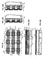
- FIG. 26A is a top view of a semiconductor substrate used in the first step of the method of manufacturing memory cells in present invention.
- FIG. 26B is a cross sectional view of the structure taken along the line CC′ in FIG. 26A ;
- FIGS. 27-32 are top views of the structures showing in sequence the next step(s) in the formation of a memory array and cells in accordance with the present invention.
- FIGS. 27A-32A are cross sectional views taken along the line A-A′ in FIGS. 27-32 illustrating in sequence the next steps in processing to form the memory cells and array in accordance with the present invention
- FIGS. 27B-32B are cross sectional views taken along the line B-B′ in FIGS. 27-32 illustrating in sequence the next steps in processing to form the memory cells and array in accordance with the present invention
- FIGS. 27C-32C are cross sectional views taken along the line C-C′ in FIGS. 27-32 illustrating in sequence the next steps in processing to form the memory cells and array in accordance with the present invention
- FIGS. 27D-32D are cross sectional views taken along the line D-D′ in FIGS. 27-32 illustrating in sequence the next steps in processing to form the memory cells and array in accordance with the present invention.
- n+ indicates a heavily doped n-type semiconductor material typically having a doping level of n-type impurities (e.g. arsenic) on the order of 10 20 atoms/cm 3 .
- p+ indicates a heavily doped p-type semiconductor material typically having a doping level of p-type impurities (e.g. boron) on the order of 10 20 atoms/cm 3 .
- FIG. 1 shows an energy-band diagram for a conductor-insulator system when an electric field is applied.
- the diagram shows a conductor 10 contacting an insulator 12 and having a Fermi-level energy 16 in its energy-band. Further, the energy-band of the insulator 12 is shown on conduction band 18 and 18 ′ for cases with and without the Image-Force effect, respectively. Additionally, there are shown barrier heights ⁇ b 20 and ⁇ bo 22 of potential barriers 24 and 24 ′ formed by the insulator 12 for cases with and without the Image-Force effect, respectively.
- the Image-Force effect is shown to alter the shape of the potential barrier from a triangle barrier 24 ′ having a sharp corner at barrier edge to a triangle barrier 24 having a smooth corner (“Image-Force potential barrier” or “Image-Force barrier”).
- the effect lowers the potential barrier from barrier height 22 to barrier height 20 by a barrier offset ⁇ b 26 , and is termed Image-Force barrier lowering effect.
- a barrier peak 28 is shown at the peak of the Image-Force barrier 24 having a location at a distance X m 30 away from an interface between conductor 10 and insulator 12 .
- the conductor can be a semiconductor, such as n+ polycrystalline Silicon (“polysilicon”), p+ polysilicon, heavily-doped polycrystalline Silicon-Germanium (“poly SiGe”), or a metal, such as aluminum (Al), platinum (Pt), Au, Tungsten (W), Molybdenum (Mo), ruthenium (Ru), tantalum (Ta), nickel (Ni), tantalum nitride (TaN), titanium nitride (TiN) etc, or alloy thereof, such as platinum-silicide, tungsten-silicide, nickel-silicide etc.
- the insulator can be a dielectric or air.
- dielectric When dielectric is considered as the insulator, material such as oxide, nitride, oxynitride (“SiON”) can be used for the dielectric. Additionally, dielectrics having dielectric constant (or permittivity) k lower or higher than that of oxide (“Low-k dielectrics” or “High-k dielectrics”, respectively) can also be considered as the material for the insulator. Such Low-k dielectrics can be fluorinated silicon glass (“FSG”), SiLK, porous oxide, such as nano-porous carbon-doped oxide (“CDO”) etc.
- FSG fluorinated silicon glass
- SiLK silicon-doped oxide
- CDO nano-porous carbon-doped oxide
- Such High-k dielectrics can be aluminum oxide (“Al 2 O 3 ”), hafnium oxide (“HfO 2 ”), titanium oxide (“TiO 2 ”), zirconium oxide (“ZrO 2 ”), tantalum pen-oxide (“Ta 2 O 5 ”) etc.
- any composition of those materials and the alloys formed thereof such as hafnium oxide-oxide alloy (“HfO 2 —SiO 2 ”), hafnium-aluminum-oxide alloy (“HfAlO”), hafnium-oxynitride alloy (“HfSiON”) etc. can be used for the dielectrics.
- insulator need not be of dielectric materials having a uniform chemical element and need not comprising single layer, but rather can be dielectric materials having graded composition on its element, and can comprise more than one layer.
- FIG. 2 shows electrons 31 transporting through the potential barriers of FIG. 1 via quantum mechanical tunneling mechanism (e.g. Fowler-Nordheim tunneling).
- the electrons 31 in the conductor 10 are at thermal temperature before tunneling through barriers 24 or 24 ′, and thus the electrons do not have kinetic energy with respect to the Fermi-level 16 .
- Such type of electrons is termed as “thermal electrons”, and such type of charge carriers is termed as “thermal charge carriers” or “thermal carriers”.
- the thermal electrons 31 are able to transport through insulator 12 in quantum mechanical tunneling when a large electric field (typically greater than 10 MV/cm) is applied in insulator.
- the electrons 31 are shown tunneling through the insulator 12 to enter its conduction band 18 and 18 ′ for cases with and without the Image-Force effect, respectively.
- Such tunneling mechanism is known to have higher tunneling rate on transporting electrons 31 through the barrier 24 than through barrier 24 ′ when barrier height is lowered by the Image-Force effect.
- FIG. 3A shows an energy band diagram for an energized charge carrier (electron 32 ) transporting over potential barrier of the conductor-insulator system of FIG. 1 .
- the energized charge carrier in a region is defined as charge carrier having a kinetic energy with respect to the Fermi-level energy of that region.
- the energized electron 32 in the conductor 10 is shown having a kinetic energy 33 with respect to the Fermi-level energy 16 of the conductor 10 .
- Such electron transports in a different mechanism than that of the thermal electron 31 described in connection with FIG. 2 .
- the kinetic energy 33 is shown at a level slightly higher than the barrier height 20 of the Image-Force barrier 24 and lower than the barrier height 22 .
- the electron 32 is shown moving along a forward direction 34 (shown in arrow) from conductor 10 to insulator 12 .
- a forward direction 34 shown in arrow
- the kinetic energy 33 is insufficient to support hot electron 32 transporting over potential barrier 24 ′, and hence electron can be blocked by the barrier 24 ′ and moving along a returned path 34 ′.
- the lowered barrier height 20 permits the hot electron 32 having same kinetic energy 33 to transport along the forward direction to graze and pass the Image-Force barrier 24 and enter its conduction band 18 .
- This effect is desirable as it can reduce voltage that is required to energize the electrons 32 in order to produce hot electrons for applications in integrated circuit (“IC”) and memory.
- FIG. 3B shows the effect of Image-Force on altering barrier height and location of the barrier peak of the Image-Force potential barrier.
- the barrier height and location of peak barrier are plotted as a function of electric field E D applied to the insulator.
- oxide is assumed as the material for the insulator.
- FIG. 3B shows that the barrier height 20 can be lowered from 3.1 eV to about 2.5 eV when an electric field E D of about 5 MV/cm is applied to the insulator.
- This effect illustrates the Image-Force barrier lowering effect. Further, it illustrates the nature of the Image-Force potential barrier that the Image-Force potential barrier 24 is electrically alterable through electric field.
- FIG. 24 illustrates a means on altering barrier height of the barrier 24 by using an electric field.
- electric field is applied by applying a voltage across the insulator.
- a voltage of about 3.0V across the oxide is required to generate 5 MV/cm.
- This Image-Force effect provides the saving on electron kinetic energy made possible by the applied electric field because the Image-Force and the potential barrier must be combated only to a distance X m , and not to infinity. Once transporting beyond the distance X m , the energized charge carrier 32 is permitted to transport over the Image-Force barrier.
- the dielectric constant of the Image-Force barrier 24 (“Image-Force dielectric constant”) and hence on enhancing the barrier lowering effect.
- Other means such as increasing charge moving velocity (e.g. by increasing its kinetic energy), can also be considered to reduce transit time, and hence reducing the Image-Force dielectric constant. This is considered as another means on altering barrier height of the Image-Force potential barrier.
- the dielectric constant can be lowered from its static value (e.g. about 3.9 for oxide) to a value near the optical one (e.g.
- FIG. 4 is an energy band diagram for one embodiment on the conductor-insulator system of the present invention showing a group of hot electrons 32 transporting through potential barrier 24 of conductor-insulator system of FIG. 1 .
- the conductor-insulator system comprises a conductor 10 having energized charge carriers 32 with an energy distribution 36 and an insulator 12 contacting the conductor 10 at an interface 14 and having an Image-Force potential barrier 24 adjacent to the interface 14 , wherein the Image-Force potential barrier 24 is electrically alterable to permit the energized charge carriers 32 transporting there over.
- the electrons 32 are shown having an energy distribution 36 on population distributed at different energy levels and the distribution is shown in a Gaussian-shape having a broad energy spectrum ⁇ 36 .
- the distribution has a peak population 36 p at the level of the kinetic energy 33 , which is at the same kinetic energy level as described in connection with FIG. 3A .
- FIG. 4 it is further shown that about a half portion (upper half portion) of the electrons have their energy greater than the barrier height 20 , and another half portion (lower half portion) of electrons have their energy lower than the barrier height 20 . Without the Image-Force barrier lowering effect, all the electrons 32 are shown blocked by the potential barrier 24 ′ formed in connection with the conduction band 18 ′.
- the upper half portion of electrons in energy spectrum are shown being able to surmount the Image-Force barrier 24 formed in connection with the conduction band 18 and transport along the forward direction 34 (shown in arrow). These electrons can enter the conduction band 18 to become electrons 32 ′ having a distribution 36 ′ in energy. Due to insufficient kinetic energy of the lower half portion of electrons 32 , these electrons are blocked by the Image-Force barrier 24 . Thus, as shown, the distribution 36 ′ of electrons 32 ′, to a first order, only reflects the distribution of the upper half portion of electrons 32 .
- FIG. 4 another Image-Force effect is worth noted and is provided herein.
- the lower half portion of the electrons 32 have a lower kinetic energy than that of the upper half one. Therefore, their transit time on traversing the distance X m 30 before reaching the peak barrier is longer than that of the upper half portion of electrons. In some situations, their transit time can be longer than the dielectric relaxation time of the insulator, and hence allowing the insulator to fully screen the Image-Force interaction with these electrons. This results in a weaker Image-Force barrier lowering effect due to a larger dielectric constant seen by such type of electrons. Such effect results in a higher barrier height 20 for the lower energy electrons and hence induces a stronger effect on blocking these electrons from surmounting the barrier 24 .
- the Image-Force effects described in FIG. 4 further provide a filtering function on passing high energy charge carriers and blocking the low energy ones.
- the selection on energy level (“threshold energy”) for carriers to be passed can be made by controlling the barrier height 20 through a selection on the electric field of the insulator based on the barrier height ⁇ b dependence on electric field E D as described in connection with FIG. 3B .
- a tunable range on threshold energy can be from 3.1 eV to about 2.5 eV as varying electric field from 0 to 5 MV/cm (or equivalently, by applying voltage from 0 to 3 V across the oxide insulator, assuming an oxide thickness of 6 nm).
- electrons having broad energy spectrum can be originated by employing mechanisms such as CHEI, SSI, and BTBT well-known in the art. Electrons energized by these types of mechanisms typically involve spherical and non-directional scatterings with lattice atoms and the energy spectrum ⁇ 36 can range from about 0.5 eV to about 3 eV.
- FIG. 5 presents an energy band diagram for another embodiment on the conductor-insulator system of the present invention showing energized charge carriers transporting over potential barrier 24 of conductor-insulator system of FIG. 1 .
- the conductor-insulator system comprises a conductor 10 having energized charge carriers 37 with an energy distribution 38 and an insulator 12 contacting the conductor 10 at an interface 14 and having an Image-Force potential barrier 24 adjacent to the interface 14 , wherein the Image-Force potential barrier 24 is electrically alterable to permit the energized charge carriers 37 transporting there over.
- the energized charge carriers (hot electrons 37 ) are shown having energy distribution 38 on population distributed in a narrow energy spectrum ⁇ 38 when transporting over Image-Force barrier 24 of conductor-insulator system.
- the diagram is in all respects except one the same as that of FIG. 4 .
- the difference is that instead of the broad energy spectrum ⁇ 36 for the hot electrons distribution 36 , the diagram is provided with a narrow energy spectrum ⁇ 38 for the hot electrons distribution 38 .
- hot electrons 37 having peak population at same energy level 33 as electrons 32 described in connection with FIG.
- the energy distribution 38 of the energized charge carriers 37 has the energy spectrum ⁇ 38 in the range of about 30 meV to about 300 meV.
- the unique portion of this embodiment is that electrons 37 are packed in a tight energy distribution and the Image-Force barrier 24 functions as a “Full-Pass Filter” permitting all the hot electrons traversing there through at a lower kinetic energy. It thus brings advantages on higher injection efficiency and lower operation voltage to this embodiment.
- FIG. 6 presents an energy band diagram for another embodiment of the present invention with holes as an example for illustration.
- the conductor-insulator system comprises a conductor 10 having energized charge carriers 40 with an energy distribution 48 and an insulator 12 contacting the conductor 10 at an interface 14 and having an Image-Force potential barrier 42 adjacent to the interface 14 , wherein the Image-Force potential barrier 42 is electrically alterable to permit the energized charge carriers 40 transporting there over.
- FIG. 6 The diagram of FIG. 6 is in all respects the same as that of FIG. 5 except few differences.
- One of the differences is that instead of providing hot electrons 37 as the transporting charge carriers, the diagram is provided with energized holes 40 (or “hot holes” 40 ).
- barriers formed by the insulator are now in connection with valence band of the insulator.
- a barrier height 41 ′ of a potential barrier 42 ′ in connection with a valence band 44 ′ for case without the Image-Force effect and a barrier height 41 of an Image-Force barrier 42 at valence band 44 of the conductor-insulator system of FIG. 1 .
- the barrier height 41 is lowered by the Image-Force barrier lowering effect in similar way as described for barrier height 20 in connection with FIGS. 1 , 3 B and 3 C while an electric field is applied to insulator.
- hot holes 40 are shown having an energy distribution 48 on population distributed in a Gaussian-shape profile having a narrow energy spectrum ⁇ 48 .
- the distribution 48 is shown having a peak distribution 48 p and a tail distribution 48 t .
- the holes at the peak distribution 48 p are shown having a kinetic energy 46 with respect to the Fermi-level 16 of the conductor.
- the kinetic energy 46 is shown slightly higher than the Image-Force barrier height 41 and lower than the barrier height 41 ′. Without the Image-Force barrier lowering effect, holes 40 having the distribution 48 are shown having their energy below barrier height 41 ′ and thus are unable to surmount the barrier 42 ′.
- holes 40 are shown having a majority portion (except the tail portion 48 t ) being able to surmount the Image-Force barrier 42 , transporting along the forward direction 34 to become holes 40 ′ having an energy distribution 48 ′ on their population.
- Such holes 40 ′ have energy higher than the valence band 44 and can continue transporting within the insulator along the same direction to reach material adjacent to the other side of the insulator (not shown).
- the high-pass filtering effect that is similar to the effect described in connection with FIG. 4 for electrons. As shown, the holes 40 within the tail distribution 48 t are shown having kinetic energy slightly below the barrier height 41 .
- Such holes are blocked from surmounting Image-Force barrier 42 and are not included in the distribution 48 ′.
- an additional small voltage e.g. about 100 mV.
- hot carriers electrosprays
- the operation voltage can be lowered when employing such effect for operating memory cell or semiconductor devices.
- carriers having tight energy spectrum on energy distribution are provided as the hot carriers and are used along with the Image-Force barrier lowering effect for memory cell operations.
- the present invention is not limited to the illustrated herein and embodiments described above, but encompasses any and all variations falling within the scope of the appended claims.
- the carriers distributions 36 , 38 and 48 of the present invention is illustrated in Gaussian shape, it should be apparent to those having ordinary skill in the art that the distribution can be extended to any other type of shapes, and the shape need not be symmetrical in the energy.
- FIG. 7 provides an energy band diagram for a conductor-filter system in accordance with another embodiment of the present invention.
- a filter 52 contacting a conductor 50 .
- the conductor 50 supplies thermal charge carriers of electrons 56 .
- the filter 52 contacts the conductor 50 and includes dielectrics 53 and 54 for providing a filtering function on the charge carriers 56 of one polarity (negative charge carriers, electrons 56 ), wherein the filter 52 includes electrically alterable potential barriers 24 53 and 24 54 for controlling flow of the charge carriers 56 of one polarity through the filter 52 in one direction (forward direction 34 ).
- FIG. 7 is an example of the filtering function.
- the conductor 50 has Fermi-level energy 16 50 and can be a semiconductor, such as n+ polysilicon, p+ polysilicon, heavily-doped polycrystalline Silicon-Germanium (“poly SiGe”), or a metal, such as aluminum (Al), platinum (Pt), Au, Tungsten (W), Molybdenum (Mo), ruthenium (Ru), tantalum (Ta), nickel (Ni), tantalum nitride (TaN), titanium nitride (TiN) etc, or alloy thereof, such as platinum-silicide, tungsten-silicide, nickel-silicide etc.
- a semiconductor such as n+ polysilicon, p+ polysilicon, heavily-doped polycrystalline Silicon-Germanium (“poly SiGe”)
- a metal such as aluminum (Al), platinum (Pt), Au, Tungsten (W), Molybdenum (Mo), ruthenium (Ru
- the filter 52 is shown comprising a tunneling dielectric TD 53 and a blocking dielectric BD 54 .
- the tunneling dielectric TD 53 is shown having a barrier 24 53 formed in the conduction band 18 53 of TD 53 .
- the blocking dielectric BD 54 is shown having a barrier 24 54 formed in the conduction band 18 54 of BD 54 and the conduction band 18 54 is shown having an offset 55 with the conduction band 18 53 of TD 53 .
- TD 53 is disposed adjacent to the conductor 50
- BD 54 is disposed adjacent to TD 53 .
- BD 54 has an energy band gap narrower than that of TD 53 .
- the filter 52 can have different band bending on conduction bands as a voltage is applied across the filter.
- the conduction band 18 54 of BD 54 is shown having a less band bending than that shown for conduction band 18 53 of TD 53 .
- the conductor 50 supplies thermal electrons 56 having an energy distribution 57 on population.
- the energy distribution 57 of electrons 56 is shown below Fermi-level energy 16 50 and has a peak distribution 57 p and a tail distribution 57 t in its distribution profile.
- the conductor 50 provides charge carriers having energy lower than Fermi-level energy, and hence functions somewhat like a “low-pass” carrier provider. With electric fields applied in the filter 52 , electrons 56 in the peak portion distribution 57 p are shown being able to transport through TD 53 in quantum mechanical tunneling mechanism (e.g.
- the barrier 24 54 of BD 54 provided in the filter 52 forms an additional tunneling barrier for the electrons 56 within the tail distribution 57 t and a blocking effect on these electrons takes place and can be made by keeping barrier 24 54 at an energy level (“threshold energy” 58 ) higher than the energy of these electrons.
- the threshold energy 58 is to first order established by both barriers 24 53 and 24 54 (it's controlled by a voltage drop in barrier 24 53 and the offset 55 between barriers 24 53 and 24 54 ).
- the blocking effect of barrier structure of filter 52 thus provides a filtering mechanism producing a high-pass filtering effect on tunneling charge carriers 56 .
- This filtering effect is unique and is somewhat different than the filtering effect on energized carriers (e.g. hot electrons 32 ) described in connection with FIG. 4 .
- TD 53 and BD 54 are shown in the filter 52 of FIG. 7 , such showing is only by way of example and any additional layers having potential barriers suitable for controlling carrier flow can be employed.
- Such layers can be a semiconductor or a dielectric and can be disposed in between TD 53 and BD 54 or can be disposed adjacent to only one of them.
- the unique portion of the conductor-filter system of FIG. 7 lies on its capability of providing charge carriers transporting in tight energy distribution. Such capability is a result of the “low-pass” carrier provider function of the conductor 50 and the high-pass filter function of the filter 52 . Combing both such functions, the conductor-filter system of FIG. 7 provides a “band-pass” filtering function that permits charge carriers having narrow energy spectrum in their distribution be transported.
- the band-pass filtering function is one embodiment of the filtering function of filter 52 , and permits the conductor-filter system functioning as a “band-pass filter” having a “bandwidth” controlled by the Fermi-level energy 16 50 and the threshold energy 58 .
- the energy spectrum is in the range from about 30 meV to about 300 meV.
- the filter 52 provides filtering effect on passing electrons having energy higher than the threshold energy 58 . This results in passing electrons in the peak distribution 57 p and blocking electrons in the tail distribution 57 t .
- the energy distribution 57 ′ of electrons 56 ′ is shown as an example illustrating the “band-pass” filtering function of the conductor-filter system of FIG. 7 , and the distribution 57 ′ is shown similar to the peak distribution 57 p of the distribution 57 to illustrate this effect.
- the energy spectrum ⁇ 57 ′ of distribution 57 ′ typically can be narrowed or widen by adjusting the threshold energy 58 at a higher or a lower level, respectively, than level shown in FIG. 7 .
- BD 54 having a larger dielectric constant relative to that of TD 53 is usually desirable for following considerations.
- the larger dielectric constant for BD 54 permits a larger portion of the applied voltage appearing across TD 53 . This enhances voltage conversion between applied voltage and voltage across TD, thus has advantages on lowering the applied voltage required for the filtering effect, increasing sensitivity of the applied voltage on the filtering effect, and increasing blocking range in energy spectrum for electrons distributed in the tail distribution.
- the conduction band offset 55 between BD and TD can be tailored at different values to control the threshold energy 58 beyond which electrons 56 in the distribution 57 are permitted to tunnel through the filter 52 . This can be done by properly choosing materials for BD 54 and for TD 53 . In a specific example, when choosing oxide as the material for TD 53 , a dielectric film of oxynitride system (“SiO x N 1-x ”) will be a good candidate for BD 54 because of its well-proven manufacturing-worthy film quality and process control.
- SiO x N 1-x a dielectric film of oxynitride system
- the fractional oxide x is changed from 0 to 1, the conduction band offset 55 can be changed from about 1 eV to 0 eV.
- a tailoring on the fractional oxide x in SiO x N 1-x permits a tailoring on the conduction band offset 55 to a desired range for filter 52 , and hence provide method on adjusting the energy spectrum ⁇ 57 ′ (i.e. the “bandwidth” of the band-pass filter) to range desired for use in practical applications.
- TD 53 and BD 54 and Fermi-level energy 16 50 of conductor 50 can also be used to provide method adjusting the threshold energy level 58 , and its level relative to the Fermi-level energy 16 50 , and hence the “band-width” of the band-pass filter.
- These parameters are considered herein in constructing the conductor-filter system of FIG. 7 .
- polysilicon, oxide, and nitride are assumed as the materials for conductor, TD 53 , and BD 54 , respectively, of the conductor-filter system of FIG. 7 .
- the oxide of TD is assumed having a thickness of 30 ⁇ .
- threshold energy 58 shows the relative energy level of the threshold energy 58 to the Fermi-level 16 50 for two cases illustrated here.
- the range where threshold energy to Fermi-level is in negative value corresponds to situation where threshold energy is at level lower than the Fermi-level, and the difference between them corresponds to the “band-width” of the band-pass filter.
- the two cases have differences on Fermi-level of the polysilicon (n+ vs. p+ polysilicon) and on applied voltage Va across the filter 52 .
- the applied voltage Va can determine the kinetic energy of electrons 56 ′ after tunneling through the filter. Referring to FIG.
- the range where threshold energy is under the Fermi-level ranges from 0 eV to about 0.4 eV as reducing a thickness of BD (“T BD ”) from about 30 ⁇ to about 20 ⁇ .
- T BD thickness of BD
- the threshold energy relative to Fermi-level of conductor can be adjusted by method adjusting thicknesses of TD and BD in the filter and/or by adjusting Fermi-level of conductor. Such method can be used to tailor the band-width of the transporting charge to a desired range for a practical application.
- the kinetic energy of transporting charge carriers can be controlled and targeted to an application by employing this method.
- the conductor-filter system of FIG. 7 can be used to provide band-pass filter function for other type of charge carriers, such as holes (e.g. light-holes (“LH”) or heavy holes (“HH”)). Similar considerations as described in connection with FIGS. 7 and 8 for electrons can be readily applied to these holes by considering the tunneling barriers of filter 52 formed in the valence band of energy band diagram. Due to the opposite charge polarity of holes to electrons, band-pass filtering holes can be done by reversing the voltage polarity across filter 52 from the one shown in FIG. 7 .
- holes e.g. light-holes (“LH”) or heavy holes (“HH”)
- LH light-holes
- HH heavy holes
- the teachings of this disclosure can be applied to modify the dielectrics of filter through which the filtered charge distribution can be tailored for the filtering effect.
- the dielectric constant of BD 54 is illustrated to be greater than that of TD 53 , it should be clear that the teaching of this disclosure can be applied to modify the BD 54 to material having dielectric constant similar to that of TD 53 to effectively pass charge carriers in peak distribution during tunneling transport.
- TD 53 and BD 54 need not be of materials having a uniform chemical element but can be materials having graded composition on its element.
- any appropriate dielectric such as aluminum oxide (“Al 2 O 3 ”), hafnium oxide (“HfO 2 ”), titanium oxide (“TiO 2 ”), zirconium oxide (“ZrO 2 ”), tantalum pen-oxide (“Ta 2 O 5 ”) etc. can be used in place of oxide, nitride, or oxynitride.
- any composition of those materials and the alloys formed thereof such as hafnium oxide-oxide alloy (“HfO 2 —SiO 2 ”), hafnium-aluminum-oxide alloy (“HfAlO”), hafnium-oxynitride alloy (“HfSiON”) etc. can be used in place of oxide, nitride, or oxynitride.
- FIG. 9 provides an energy band diagram of a charge-injection system for one embodiment of the present invention on injecting charges having tight energy distribution.
- the energy band structure of the charge-injection system is illustrated on injecting electrons.
- a conductor-filter system 59 of the type described in connection with FIG. 7 a conductor-insulator system 60 of the type described in connection with FIGS. 1 and 5 , a charge storage region (“CSR”) 66 , a channel dielectric (“CD”) 68 , and a body 70 .
- CSR charge storage region
- CD channel dielectric
- the conductor-filter system 59 comprises a tunneling-gate (“TG”) 61 , and a charge filter 52 .
- the filter 52 includes potential barriers 24 53 and 24 54 , and has a threshold energy 58 established by the barriers for controlling its filtering effect as described in connection with FIG. 7 .
- the filter 52 further comprises the tunneling dielectric (“TD”) 53 and the blocking dielectric (“BD”) 54 as described in connection with FIG. 7 .
- the conductor-insulator system 60 comprises a ballistic gate (“BG”) 62 and a retention dielectric (“RD”) 64 as the conductor and the insulator of the system, respectively.
- the energy band diagram of the charge-injection system in regions from TG 61 to RD 64 is constructed by “contacting” the filter 52 of the conductor-filter system 59 to the conductor (BG 62 ) of the conductor-insulator system 60 .
- TG 61 and BG 62 are of metals having work function with Fermi-levels 16 61 and 16 62 , respectively.
- CSR 66 is shown insulated from BG 62 and body 70 by dielectrics RD 64 and CD 68 , respectively, and comprises semiconductor having a conduction band 18 66 and a valence band 44 66 and of n-type conductivity.
- CSR 66 may comprise semiconductor of other type of conductivity (e.g. p-type), and may comprise metal or any other suitable material (e.g. nano-particles or traps in dielectrics) used for storing charge carriers.
- Body 70 comprises semiconductor having conduction bands 18 70 , and valence band 44 70 , respectively, and can be used to modulate an Image-Force barrier 24 64 of the conductor-Insulator system 60 by coupling voltage into CSR 66 through CD 68 .
- Dielectrics RD 64 and CD 68 are shown in single layer and can generally comprise more than one layer to form a composite layer.
- FIG. 9 further provides illustration on process forming and injecting charges having tight energy distribution.
- thermal electrons 56 having an energy distribution 57 on population be supplied by TG 61 as supplied carriers. These electrons 56 are filtered by filter 52 during their tunneling transport through the filter 52 via mechanisms described in connection with FIG. 7 . After filtered, thermal electrons become electrons 56 ′ having a tighter energy distribution 57 ′ than the distribution 57 before filtered. Such electrons 56 ′ are fed to the conductor-insulator system 60 .
- a portion of the electrons 56 ′ can transport through BG 62 without scattering (“ballistic transport”) at a kinetic energy 33 higher than the Fermi-level 16 62 of BG 62 to become energized electrons 37 at the interface of BG 62 and RD 64 .
- Such electrons 37 (termed “ballistic electrons”) do not experience scattering with other particles (e.g. electrons, phonons etc.), and hence can conserve their kinetic directional energy and momentum along original movement.
- electrons 56 ′ can transport through BG 62 in partial scattering (“partially ballistic transport”) with other particles and can still maintain their kinetic energy 33 high enough and directional toward the interface of BG 62 and RD 64 to become electrons 37 .
- such energized electrons 37 can surmount a barrier height 20 of the Image-Force barrier 24 64 in mechanism as described in connection with FIGS. 3B and 5 , entering a conduction band 18 64 of RD 64 , making their way there through to become electrons 37 ′ having an energy distribution 38 ′ on their population, and finally got collected and stored on CSR 66 as electrons 71 in the conduction band 18 66 .
- Such process in forming and injecting charges is termed as ballistic-charge injection mechanism.
- electrons are selected as the charge carriers, such mechanism is termed as ballistic-electron injection.
- the energy distribution of the energized charge carriers (electrons 37 ) has an energy spectrum in the range of about 30 meV to about 300 meV.
- the injection efficiency (defined as the ratio of number of carriers collected to the number of carriers supplied) of such electrons typically ranges from about 10 ⁇ 4 to about 10 ⁇ 1 .
- the injection efficiency can be further enhanced by injecting piezo-electrons (see the piezo-ballistic-electron injection mechanism as described in connection with FIG. 17 B).
- the ballistic-charge injection shown in FIG. 9 illustrates the ballistic-electron injection and is done by applying a voltage between TG 61 and BG 62 such that electrons 37 have a kinetic energy 33 higher than the Image-Force barrier height 20 of the conductor-insulator system 60 .
- Such voltage can be lowered by lowering barrier height 20 of the Image-Force barrier 24 64 by using means as described in connection with FIGS. 3A , 3 B and 3 C. This can be done by for example coupling a positive voltage (e.g. from about +1 V to about +3 V) to CSR 66 .
- the barrier height 20 can be lowered by choosing material for CSR 66 having a lower work-function (or a higher Fermi-level energy) than that of BG 62 .
- FIG. 10 provides an energy band diagram for another embodiment of the charge-injection system on injecting electrons having tight energy distribution.
- the conductor 61 supplies thermal charge carriers 56 .
- the filter 52 contacts the conductor 61 and includes dielectrics 53 and 54 for providing a filtering function on the charge carriers 56 of one polarity (negative charge carriers), wherein the filter includes electrically alterable potential barriers 24 53 and 24 54 for controlling flow of the charge carriers 56 of one polarity through the filter 52 in one direction (forward direction 34 ).
- the filter 52 further includes electrically alterable potential barriers 42 53 and 42 54 for controlling the flow of charge carriers of an opposite polarity (positive charge carriers, LH 72 and HH 73 ) through the filter in another direction (backward direction 74 ) that is substantially opposite to the one direction.
- Such filtering function permits charge carriers of one polarity type transporting along the forward direction 34 (i.e. from TG 61 to BG 62 ) and blocks charge carriers of an opposite polarity type transporting along a backward direction 74 (i.e. from BG 62 to TG 61 ).
- the filter 52 provides a charge-filtering function that can “purify” the charge flow.
- the charge-filtering function is another embodiment of the filtering function of filter 52 .
- FIG. 10 is in all respects the same as that of FIG. 9 except few differences.
- these conductor regions i.e. TG 61 and BG 62
- semiconductor having conduction band 18 61 and valence band 44 61
- conduction band 18 62 and valence band 44 62 for TG 61 and BG 62
- TG 61 is shown of a p-type semiconductor having thermal electrons 56 in the valence band 44 61 as the supplied carriers.
- Such electrons 56 and their energy distribution 57 go through identical transport processes as described in connection with FIG. 9 , and a portion of electrons 56 are able to enter CSR 66 to become electrons 37 ′ having energy distribution 38 ′, and finally be collected and stored on CSR 66 as electrons 71 in similar way as described in connection with FIG. 9 .
- the energy band structure in FIG. 10 shows the backward-transporting carriers (i.e. LH 72 and HH 73 ) has to transport through more barriers than the forward-transporting carriers (i.e. electrons 56 ) do, and hence provides filtering effect on blocking the backward-transporting carriers.
- the filtering effect is based on the energy band structure constructed by potential barriers in filter 52 .
- a first potential barrier 42 54 blocking the backward transporting holes 72 and 73 comprises barrier heights 41 54 and 41 ′ 54 at an entrance side and at an exit side of barrier 42 54 , respectively. Both barrier heights 41 54 and 41 ′ 54 are referenced to valence band 44 54 of BD 54 .
- a second potential barrier 42 53 having a barrier height 41 53 at its entrance side forms another barrier blocking holes 72 and 73 .
- the barrier height 41 53 is referenced to valence band 44 53 of TD 53 at the interface between TD 53 and BD 54 .
- the filter 52 provided herein is based on a barrier height engineering concept.
- One specific embodiment on the conductor-filter and conductor-insulator systems 59 and 60 that is used for illustrating the concept comprises a p+ polysilicon for TG 61 , an oxide layer for TD 53 , a nitride layer for BD 54 , an n+ polysilicon for BG 62 , and an oxide layer for RD 64 .
- the n+ polysilicon is considered for BG 62 due to several considerations. A major consideration lies in the much higher solid solubility for n-type impurities (e.g. Arsenic, phosphorous etc) than that for p-type impurities (e.g. Boron).
- Impurity with a higher solid solubility is desirable as it usually can dope the silicon heavier to result in a lower sheet resistance, and is favorable for integrated circuits (IC) application.
- polysilicon is employed as the material for TG 61 and BG 62 due to its well proven yield, manufacturability, and compatibility with state of the art IC technology.
- An oxide with a thickness of about 7 nm to 10 nm is employed for RD 64 due to the same reason.
- the oxide layer used for TD 53 can be with a thickness in the range of about 1.5 nm to 4 nm and preferably in the range of about 2 nm to 3.5 nm.
- the thickness of TD 53 layer is chosen in the range where charge-carriers (electrons, LH or HH) transporting across the layer are primarily through the direct tunneling mechanism.
- the thickness of BD 54 is chosen to block any type of charge-carriers from tunneling transport through both BD 54 and TD 53 layers when a modest voltage in the range of about 1 V to about 2.5V is applied between TG 61 and BG 62 .
- the thickness of BD 54 is further chosen to permit one type of charge carriers (e.g. electrons) transporting in the forward direction and to block the other type of charge carriers (e.g. LH) from transporting in the backward direction when in a higher voltage range (3V or higher).
- the selection on thickness of BD 54 is also determined by it dielectric constant.
- the thickness of BD 54 can be thinner or thicker than that of TD 53 provided filter 52 can effectively meet the forgoing requirements.
- the minimum thickness for BD 54 can be about 2 nm (or 20 ⁇ ) or thicker.
- the oxide for TD 53 can be a HTO (high temperature oxide) or a TEOS layer formed by using conventional deposition technique, or a thermal oxide by using thermal oxidation technique well-known in the art.
- the nitride for BD 54 can be a high quality nitride without charge trapping centers in its band gap.
- This high quality nitride can be formed in NH 3 (ammonia) ambient at a high temperature (e.g. 1050° C.) by using, for example, RTN (Rapid Thermal Nitridation) technique well-known in the art.
- TD 53 can comprises oxide having a thickness in a range of about 1.5 nm to about 4 nm and BD 54 can comprises material selected from the group consisting of nitride, oxynitride, Al 2 O 3 , HfO 2 , TiO 2 , ZrO 2 , Ta 2 O 5 , and alloys formed thereof.
- TD 53 can comprises oxynitride having a thickness in a range of about 1.5 nm to about 4 nm and BD 54 can comprises material selected from the group consisting of nitride, Al 2 O 3 , HfO 2 , TiO 2 , ZrO 2 , Ta 2 O 5 , and alloys formed thereof.
- FIG. 11 illustrates an energy band diagram similar to that in FIG. 10 except with less band bending in the energy band of filter 62 to reveal more details on barrier heights.
- a barrier height 41 ′ 53 of valence band offset between 44 62 and 44 53 is shown in FIG. 11 .
- the barrier height 41 ′ 53 is at the exit side of the second hole potential barrier 42 53 for blocking the backward transporting LH 72 and HH 73 .
- a first electron potential barrier 24 53 formed by TD 53 and having barrier heights 20 53 and 20 ′ 53 at the entrance and the exit sides, respectively, of barrier 24 53 for blocking the forward transporting electrons 56 .
- a second electron potential barrier 24 54 formed by BD 54 and having barrier heights 20 54 and 20 ′ 54 at the entrance and the exit sides of barrier 24 54 , respectively.
- the second electron potential barrier 24 54 also has the effect on blocking the forward transporting electrons 56 .
- ⁇ CB — TB is the conduction band offset between TG 61 and BD 54 when under the flat-band condition
- ⁇ VB — GT is the valence band offset between BG 62 and TD 53 under flat-band condition
- barrier height 20 54 ( ⁇ VE — TB ) and barrier height 41 53 ( ⁇ VH — GT ) have different dependence on Va.
- the barrier height dependence on voltage is asymmetrical and is primarily determined by the combined effects of dielectric constant and dielectric thickness (i.e. the “ ⁇ T effect”).
- FIG. 12A illustrates an example on the barrier height engineering concept using the theory described herein for ballistic-electron-injection.
- the barrier height 20 54 ( ⁇ VE — TB ) for electrons at TG 61 decreases faster than the barrier height 41 53 ( ⁇ VH — GT ) for LH 72 and HH 73 in BG 62 .
- barrier height 41 53 has a weaker voltage-dependence than barrier height 20 54 .
- the barrier height 20 54 ( ⁇ VE — TB ) in fact are shifted under the Fermi-level energy 16 61 (i.e.
- FIG. 10 illustrates the energy band diagram for situation when the applied voltage is decreased beyond this voltage level.
- the second barrier 24 54 for electrons 56 shown in FIG. 11 is now under Fermi-level energy 16 61 as the applied voltage is decreased beyond this voltage level. Therefore, electrons 56 of TG 61 having energy higher than the threshold energy 58 can transport through filter 52 without being blocked by BD 64 layer. This permits the band-pass filtering function of the conductor-filter system 59 to inject electrons having tight energy distribution 57 ′ along the forward direction 34 .
- barrier height 41 53 ( ⁇ VH — GT ) on the applied voltage maintains the barrier 42 53 for blocking holes in this voltage range and hence can prevent holes from backward transport. Therefore, the barriers engineering concept here actually provides a method through which an electrically alterable filter is constructed for ballistic-electron-injection.
- the filter provides unique feature filtering out the unwanted carriers (i.e. the backward transporting LH 72 and HH 73 ) without affecting the transport of the wanted carriers (i.e. the forward transporting electrons 56 ).
- V BD voltage across BD
- barrier height 41 54 forms one side of the barrier 42 54 (the entrance side for holes 72 and 73 ) and barrier height 41 ′ 54 forms the other side of the barrier (the exit side for holes 72 and 73 ).
- the barrier height 41 ′ 54 at the exit side of the trapezoidal barrier 42 54 to first order equals ⁇ VB — GB ⁇ V BD , where ⁇ VB — GB is the barrier height 41 54 .
- the barrier height 41 ′ 54 is about 0.7 eV, and hence the trapezoidal structure for barrier 42 54 is maintained. It is clear that barrier height 41 ′ 54 can be made higher by lowering V BD through optimizing dielectric constant and thickness of TD 53 and BD 54 , as taught in the foregoing theory.
- voltage of TG 61 is chosen in the range of about ⁇ 3.5 V to about ⁇ 4.5 V relative to voltage of BG 62 for the ballistic-electrons-injection.
- Such voltage can be further lowered by lowering the Image-Force barrier height 20 of the conductor-insulator system 60 as described in connection with FIGS. 3A , 3 B and 3 C. This can be done by coupling a voltage in the range of about 1 V to about 3 V to CSR 66 .
- the Image-Force barrier can be lowered by choosing material for CSR 66 having a smaller work-function (or a higher Fermi-level energy) than that of BG 62 .
- Lowering voltage applied between TG 61 and BG 62 by lowering the Image-Force barrier brings desirable effects to the present invention.
- One of the major advantages is on lowering the electric field in dielectrics between TG and BG, and can prevent high-field related problems from occurring in the dielectrics (e.g. dielectric breakdown, which can result in permanent damage to the dielectrics).
- the filter 52 further provides a voltage divider function in accordance with another embodiment of the present invention.
- the voltage-divider function reduces voltage drops in the dielectrics of the filter 52 .
- FIG. 12B illustrates an example on the voltage divider function using the barrier height engineering concept described herein for ballistic-electron-injection.
- FIG. 12B there is shown voltages across various dielectrics versus voltage across the filter 52 .
- the voltage across the filter 52 and hence voltage applied between TG 61 and BG 62 , is divided and shared by regions within the filter 52 .
- the voltage divider function provided by the filter 52 thus permits voltage applied between TG 61 and BG 62 be divided and shared by BD 54 and TD 53 without compromising ballistic-charge-injection.
- the voltage divider function reduces the voltage withheld by each of these dielectrics and can prevents the dielectric breakdown problem.
- One of the unique portions of the present invention lies in the effects provided by the barrier height engineering concept and its implementation in the filter 52 .
- Such effects provide the voltage divider function and prevent dielectric breakdown problem that can happen during the charge injection.
- impact-ionization problem in TG 60 which can be triggered by the backward transporting charge carriers, can be effectively prevented while suppressing these carriers from backward transport by employing the filtering effect on charge blocking.
- the filter and the energy band structure illustrated in the present invention can effectively block charge carriers of one polarity type from transporting along a backward direction while passing charge carriers of an opposite polarity type transporting along a forward direction during the ballistic-charge-injection.
- the filter 52 provides a charge-filtering function that can “purify” the charge flow.
- the material for BG 62 has a Fermi level in the flat band condition lies in about the middle of the energy band gap of BD 54 of filter 52 to best utilize the charge-filtering function when the band structure and the injection mechanism are employed in constructing memory cells.
- FIG. 13 provides an energy band diagram to illustrate the ballistic-charge-injection and filtering effect for holes in the charge-injection system of the FIG. 10 type.
- the conductor 61 supplies thermal charge carriers 75 and 76 .
- the filter 52 contacts the conductor 61 and includes dielectrics 53 and 54 for providing a filtering function on the charge carriers 75 and 76 of one polarity (positive charge carriers), wherein the filter includes electrically alterable potential barriers 42 53b and 42 54b for controlling flow of the charge carriers 75 and 76 of one polarity through the filter 52 in one direction (forward direction 34 ).
- the filter 52 further includes electrically alterable potential barriers 24 53b and 24 54b for controlling the flow of charge carriers of an opposite polarity (negative charge carriers, electrons 84 ) through the filter in another direction (backward direction 74 ) that is substantially opposite to the one direction.
- Such filtering function permits charge carriers of one polarity type transporting along the forward direction 34 and blocks charge carriers of an opposite polarity type transporting along a backward direction 74 .
- the filter 52 provides a charge-filtering function that can “purify” the charge flow.
- the charge-filtering function is another embodiment of the filtering function of filter 52 , and is similar to the charge-filtering function as described in connection with FIG. 10 .
- LH 75 and HH 76 in the valence band 446 , of TG 61 as the supplied carriers for injection.
- LH 75 and HH 76 are shown transporting along the forward direction 34 in an energy distribution 77 on their population.
- energy distribution for LH 75 and HH 76 are shown in same distribution 77 , it is noted that LH 75 and HH 76 can have different energy distributions on their population due to differences on their effective masses.
- both LH 75 and HH 76 are shown transporting through barriers of filter 52 in quantum mechanical tunneling mechanism to become LH 75 ′ and HH 76 ′ having a kinetic energy 46 with respect to the valence band of BG 62 that is slightly higher than a barrier height 41 of an Image-Force barrier 42 64 .
- these carriers transport further along the forward direction, their transport behaviors through BG 62 are very different due to their difference on effective mass.
- HH 76 ′ due to their heavy effective mass, the mean-free-path can be very short. Therefore, HH 76 ′ are prone to experience scattering events with other particles (e.g. phonons), and have low ballistic transport efficiency (“ballisticity”).
- FIG. 13 both LH 75 and HH 76 are shown transporting through barriers of filter 52 in quantum mechanical tunneling mechanism to become LH 75 ′ and HH 76 ′ having a kinetic energy 46 with respect to the valence band of BG 62 that is slightly higher than a barrier height 41 of an Image-For
- HH 76 ′ are shown experiencing scattering events and losing their energy to become HH 79 . Further, these scattered HH 79 are shown having a broad energy distribution 81 than original one 77 due to scattering. Such holes 79 are shown transporting at energy below a barrier height 41 of an Image-Force barrier 42 64 at the valence band 44 64 of RD 64 , and hence are blocked from transporting over barrier 42 64 and cannot enter CSR 66 .
- the LH 75 ′ has a lighter effective mass, and hence a much longer mean-free-path than that of HH 76 ′ (for example, in silicon, the mean-free-path of LH is about 3 times of that of HH).
- LH 75 ′ can transport through BG 62 , without scattering (i.e. in ballistic transport), at the kinetic energy 46 to become energized charge carriers LH 78 at the interface of BG 62 and RD 64 .
- LH 78 also termed “ballistic LH”
- LH 75 ′ can transport through BG 62 in the partial ballistic scattering, and still can maintain their kinetic energy 46 high enough and directional toward the interface of BG 62 and RD 64 to become LH 78 .
- LH 78 can surmount the barrier height 41 of the Image-Force barrier 42 64 in mechanism as described in connection with FIG. 6 , entering a valence band 44 64 of RD 64 , making their way there through to become LH 78 ′ having an energy distribution 80 ′ on their population, and finally got collected and stored on CSR 66 as holes 82 in the valence band 44 66 .
- Such process in filtering and injecting hole charges is termed as ballistic-holes-injection mechanism.
- the energy distribution 80 of the energized charge carriers (LH 78 ) has an energy spectrum in the range of about 30 meV to about 300 meV.
- the injection efficiency (defined as the ratio of number of carriers collected to the number of carriers supplied) of such holes typically ranges from about 10 ⁇ 6 to about 10 ⁇ 3 .
- the injection efficiency can be further enhanced by injecting piezo-holes (see the piezo-ballistic-hole injection mechanism as described in connection with FIGS. 17 B, 17 C).
- voltage of TG 61 is chosen in the range of about +5 V to about +6.0 V relative to voltage of BG 62 for the ballistic-holes-injection.
- Such voltage can be further lowered by lowering the Image-Force barrier height 41 of the conductor-insulator system 60 as described in connection with FIG. 6 . This can be done by for example coupling a voltage in the range of about ⁇ 1 V to about ⁇ 3 V to CSR 66 .
- the Image-Force barrier height can be lowered by choosing material for CSR 66 having a larger work-function (or a lower Fermi-level energy) than that of BG 62 .
- the voltage applied between TG 61 and BG 62 can be further reduced by employing materials having similar Fermi-level energy for these regions.
- the charge-injection system can comprise a p+ polysilicon for TG 61 , an oxide layer for TD 53 , a nitride layer for BD 54 , a p+ polysilicon for BG 62 , and an oxide layer for RD 64 .
- Such embodiment allows voltage of TG 61 relative to voltage of BG 62 be chosen in a lower range (e.g. from about +4.5 V to about +5.5 V) for the ballistic-holes-injection.
- FIG. 13 further shows that electrons 84 in conduction band 18 62 of BG 62 can transport along the backward direction 74 while biasing the energy band structure in the voltage polarity for transporting LH 75 and HH 76 along the forward direction 34 .
- the backward transporting electrons 84 can result in undesired problems such as impact-ionization in TG 61 , current and power waste etc. that are similar to those problems caused by backward transporting holes as described in connection with FIG. 10 . It is thus desirable to block electrons 84 from backward transporting into TG 61 by using the filter 52 .
- the energy band structure in FIG. 13 shows the backward-transporting carriers (i.e. electrons 84 ) have to transport through more barriers than the forward-transporting carriers (i.e. LH 75 and HH 76 ) do.
- a first electron barrier 24 54b blocking the backward transporting electrons 84 comprises barrier heights 20 54b and 20 ′ 54b at an entrance side and an exit side, respectively, of the barrier 24 54b .
- Barrier heights 20 54b and 20 ′ 54b are referenced to conduction band 18 54 of BD 54 at interface between BD 54 and BG 62 and between TD 53 and BD 54 , respectively.
- a second electron barrier 24 53b is shown having a barrier height 20 53b at its entrance side and forms another barrier blocking electrons 84 .
- the barrier height 20 53b is referenced to conduction band 18 53 of TD 53 at the interface between TD 53 and BD 54 .
- a barrier height 20 ′ 53b (not shown) exists at an exit side of barrier 24 53b , and is referenced to conduction band 18 53 of TD 53 at the interface between TG 61 and TD 53 .
- barrier height 20 ′ 53b is below the energy level of electrons 84 , and hence is not shown in FIG. 13 .
- Both barriers 24 54b and 24 53b form an energy band structure in the conduction band of filter 52 to block backward-transporting electrons 84 .
- a first potential barrier 42 53b is formed by TD 53 and has barrier heights 41 53b and 41 ′ 53b at the entrance and the exit sides, respectively, of barrier 42 53b .
- a second barrier 42 54b is formed by BD 54 and has barrier heights 41 54b and 41 ′ 54b (not shown) at the entrance and the exit sides of barrier 42 54b , respectively.
- Both the first and the second barriers 42 53b and 42 54b form energy band structure in the valence band of filter 52 and have effect on blocking the forward transporting holes 75 and 76 . In FIG. 13 , the energy band structure is biased to inject holes.
- Both barrier heights 41 54b and 41 ′ 54b are below the energy level of forward transporting holes, and hence are not shown in FIG. 13 .
- FIG. 14 illustrates the effect of the barrier height engineering in accordance with the present invention for ballistic-holes-injection, wherein the barrier height 20 ′ 54b of the backward transporting electrons is shown having a weaker voltage-dependence on voltage drop across filter 52 (i.e. voltage between TG 61 and BG 62 ) than the barrier height 41 54b of the forward transporting holes has.
- the two barrier heights 20 ′ 54b and 41 54b can be altered in different degree by voltage drop across filter 52 .
- This barrier height dependence on voltage is asymmetrical and is primarily governed by the combined effects of dielectric constant and dielectric thickness (i.e. the “ ⁇ T effect”), as illustrated in the barrier height engineering theory.
- barrier height 41 54b for holes 65 and 76 of TG 61 decreases faster than the barrier height 20 ′ 54b for electrons 84 in BG 62 .
- barrier height 20 ′ 54b has a weaker voltage-dependence than barrier height 41 54b .
- the barrier height 41 54b in fact is shifted below hole energy (i.e. at barrier height equals zero) at an applied voltage of about +3.5V while there is still a sufficient barrier height of about +2.5 eV remained for the barrier height 20 ′ 54b .
- FIG. 13 illustrates the energy band diagram for situation when the applied voltage is increased beyond this voltage level. As shown in FIG.
- the second barrier 42 54b for holes 75 and 76 is below hole energy as the applied voltage is increased beyond this voltage level. Therefore, holes 75 and 76 of TG 61 can transport through filter 52 without being blocked by BD 64 layer.
- the much weaker dependence of barrier height 20 ′ 54b on the applied voltage maintains the barriers 24 54b and 24 53b for blocking electrons 84 in this voltage range and hence preventing electrons from backward transporting.
- FIG. 14 The illustration made in FIG. 14 is by way of example showing the asymmetrical voltage-dependence of barrier heights on two barrier heights 20 ′ 54b and 41 54b . Similar showing can be readily made on other barrier heights (such as 20 53b and 41 ′ 53b of barriers 24 53b and 42 53b , respectively) of filter 52 in FIG. 13 . It is thus clear that the barrier heights of the potential barriers controlling the backward transporting charge carriers have a weaker voltage-dependence on voltage drop across the filter than barrier heights of the potential barriers controlling the forward transporting charge carriers have.
- the filter also provides voltage divider function while voltage polarity between TG and BG is set for ballistic-hole injection.
- the voltage divider function for ballistic-hole injection reduces voltage drops in the dielectrics of the filter 52 , and is governed by similar effect as that described in connection with FIG. 12B for ballistic-electron injection.
- the voltage divider function reduces the electric fields within dielectrics of filter 52 by reducing the voltage drops across them and thus prevents the dielectric breakdown problem.
- the barriers engineering concept here provides a method through which an electrically alterable filter is constructed for ballistic-charge-injection.
- the filter provides unique feature filtering out the unwanted carriers (i.e. the backward transporting carriers) without affecting the transport of the wanted carriers (i.e. the forward transporting carriers).
- the filter 52 further provides another filtering function in accordance with the present invention.
- Such filtering function permits charge carriers of one polarity type and having lighter mass (e.g. LH) to transport through the filter, and blocks charge carriers of the same polarity type and having a heavier mass (e.g. HH) from transporting there through.
- the filter 52 provides a mass-filtering function that can filter the charge carrier flows based on their mass.
- FIG. 15 illustrates the basis of the mass-filtering function of the filter 52 .
- the mass-filtering function can be better captured by referring back to FIG. 13 .
- the conductor 61 supplies thermal charge carriers (LH 75 and HH 76 ).
- the filter 52 contacts the conductor 61 and includes dielectrics 53 and 54 for providing a filtering function on the charge carriers 75 and 76 of one polarity (positive charge carriers), wherein the filter includes electrically alterable potential barriers 42 53b and 42 54b for controlling flow of the charge carriers 75 and 76 of one polarity through the filter 52 in one direction (forward direction 34 ).
- FIG. 15 shows normalized tunneling probability calculated for LH and HH and is plotted as a function of the reciprocal of V TD to illustrate the mass-filtering function of filter 52 .
- filter 52 is assumed comprising TD 53 of oxide having 3 nm on thickness and BD 54 of nitride having 2 nm on thickness.
- the tunneling probability of HH is shown lower than that of LH by about 4 to about 8 orders of magnitude.
- the difference on tunneling probability due to the effect of carrier masses permits mass-filtering function realized in the filter 52 .
- the illustration made herein is on hole carriers, the same illustration can be readily extended to other types of carriers having same polarity type but different mass (for example, piezo-electrons as described in connection with FIGS. 17B and 17C ).
- the mass-filtering function is another embodiment of the filtering function of filter 52 .
- the mass-filtering function of filter 52 and its application on passing LH brings desirable advantages to the present invention. For example, it can avoid wasting on the supplied carriers of TG 61 that are used for ballistic injection. This is because the majority population of the hole carriers in TG 61 are of the HH type, which has a shorter mean-free-path and prone to experience scattering events when transporting across BG 62 . Such HH cannot efficiently contribute to the ballistic injection and thus are wasted when employed as the supplied carriers.
- the mass-filtering function of filter 52 By filtering out the HH through the mass-filter function of filter 52 , the primary supplied carriers are now limited to LH carriers only. LH carriers have a longer mean-free-path and can more efficiently contribute to the ballistic injection while transporting through BG 62 via mechanism described in connection with FIG. 13 .
- the mass-filtering function of filter 52 provides feature on selecting carriers having high ballisticity as the supplied carriers, and hence avoids waste on supplied current by carriers of low ballisticity.
- the filter 52 of the conductor-filter system 59 provides unique filtering functions. It provides the band-pass filtering function as described in connection with FIG. 7 , the charge-filtering function as described in connection with FIGS. 10 , 12 A, 13 and 14 , and the mass-filtering function as described in connection with FIG. 15 . In addition to the filtering function, the filter 52 provides an additional voltage divider function as described in connection with FIG. 12B . It should be clear to those of ordinary skill in the art that the teachings of this disclosure can be applied to modify the dielectrics and/or architecture of the filter through which these functions can be tailored individually or collectively. For example, the filter can contain more than two dielectrics to enhance its voltage-divider function.
- the dielectrics of filter need not be having a uniform chemical element but rather can have a graded composition on its element that can effectively support these functions. It is thus understood that the present invention is not limited to the illustrated herein and embodiments described above, but encompasses any and all variations falling within the scope of the appended claims.
- FIG. 16 provides an energy band diagram in flat-band condition for another embodiment on energy band structure of the charge-injection system in accordance with the present invention.
- the band structure is in all respects except one the same as that of FIG. 11 .
- the diagram is provided with BG 62 be comprised of a metal having work function with a Fermi-levels 16 62 , such as materials for conductor described in connection with FIG. 1 .
- FIG. 16 further shows charge carriers of electrons 56 , LH 75 , and HH 76 , in valence band 44 61 of TG 61 .
- Such electrons 56 are filtered by filter 52 and are injected onto CSR 66 by applying proper voltage and polarity to TG 61 and BG 62 as described in connection with FIGS. 7 , 12 A, and FIG. 10 .
- LH 75 and HH 76 are filtered by filter 52 and are injected onto CSR 66 by applying proper voltage and polarity to TG 61 and BG 62 as described in connection with FIGS. 14 , 15 , and FIG. 13 .
- BG 62 forms the active layer for ballistic charges transport and is generally required to have a thickness thinner than a few times of the mean-free path of charge carriers (typically in the range of 10 nm to 20 nm), in order to permit such carriers transporting through BG 62 with good efficiency.
- the needs on a thin thickness for BG 62 layer unavoidably results in a large sheet resistance R to that layer, and cause fundamental problems in IC applications. For example, it can cause a large signal delay due to a combining effect of the large sheet resistance R and a large C (i.e. the RC delay).
- the RC delay can limit the speed on accessing a memory cell when embedded in a large memory array.
- an optimum set of predetermined voltages usually are required to be applied to those cells.
- voltages on un-selected cells can be different than the desired values, and hence cell disturb is more prone to happen.
- the large R can combine with a large current I to result in a IR effect, which can cause a voltage drop when passing a voltage in a signal line. The effect prevents the voltage on a designated electrode of a memory cell from reaching its desired level, and hence can adversely impact cell operation.
- the adverse impact on an unselected cell can be an undesired cell disturb, where the cell state is unintentionally changed from one logic state (e.g. a “0”) to the other (e.g. a “1”).
- the IR impact on a selected cell can be a slower speed on cell operations (i.e. program, erase, and read operations).
- Piezo-effect is a well-known physical phenomenon in solid-state physics. Piezo-effect can change electrical properties of a semiconductor material when a mechanical stress is applied to such material (see Pikus and Bir, Symmetry and Strain-Induced Effects in Semiconductors, New York: Wiley, 1974).
- the mechanical stress can be originated from a strain source (also can be termed as “stressor”) that is either internal or external to the material. This mechanical stress can be either in compressive form (compression), or in tensile form (tension), and can results in a strain in the material. It breaks the symmetry within the crystal lattice and hence deforms the potential therein.
- Some well-known applications of the piezo-effect on semiconductors are piezo-resistive effect in resistors, piezo-junction effect in bipolar transistors and diodes, piezo-Hall effect in sensors, and piezo-FETs in MOS transistors (“MOSFETs”).
- the present invention further provides the application of the piezo-effect to the ballistic charge carrier injection and transport.
- a novel piezo-ballistic-charge-injection mechanism is provided with illustrations made herein to various embodiments of the present invention.
- FIGS. 17A , 17 B and 17 C provide schematic diagrams illustrating the dispersion relationship between energy E and momentum vector k for a semiconductor without strain (or “unstrained”), under tensile stress (tensile strained), and under compressive stress (compressive strained), respectively.
- FIG. 17A shows dispersion relationship for a semiconductor without strain.
- electrons 85 filled in two conduction band valleys, a left valley 86 and a right valley 87 , having minima 86 m and 87 m , respectively.
- the minima 86 m and 87 m are shown at similar energy level.
- the left valley 86 has a heavier effective mass than the right one 87 .
- dispersion curves for LH and HH sub-bands 88 and 89 filled with holes 90 .
- LH and HH sub-bands 88 and 89 are shown having energy degeneracy at a valence band maximum 91 .
- the conduction band minima 86 m or 87 m and the valence band maximum 91 are separated by an energy band gap 92 .
- FIG. 17B shows dispersion relationship similar to FIG. 17A except the semiconductor is strained with tensile stress.
- the conduction band valleys are shown shifted with their minima moving upward (in the left valley 86 ) or downward (in the right valley 87 ). This shift redistributes the electron population within the two valleys, where electrons 85 are more populated in the valley 87 due to a lower energy level on the conduction band minimum 87 m .
- Repopulating electrons 85 to reside primarily in valley 87 is desirable for two reasons. First, it provides desirable effect on electron transport in the semiconductor due to the lighter electron effective mass in the conduction valley 87 . Second, the separation of the valleys is known being able to reduce inter-valley scattering of electrons.
- the strain in silicon can cause splitting of the six-fold degenerate conduction band into two-fold and four-fold degenerate valleys with most electrons (about 100 percent of the entire electrons) populated in the two-fold degenerate valley having lighter effective mass along electron transport direction.
- This strain effect is known to increase electron mobility by about 50 percent and drift velocity by about 16 percent in strained-Si MOSFETs (a type of piezo-FETs, see Vogelsang et al., “Electron Mobilities and High-Field Drift Velocity in Strained Silicon on Silicon-Germanium Substrate”, IEEE Trans. on Electron Devices, pp. 2641-2642, 1992).
- piezo-electrons can be employed as the supplied carriers in energy band structures in connection with FIGS. 9 and 10 to go through transport process as described therein.
- FIG. 17B also illustrates the strain effect of tensile stress in semiconductor can further remove the degeneracy of valence sub-bands 88 and 89 , where the LH sub-band 88 is shown shifted upward and the HH sub-band 89 is shown shifted downward.
- a maximum 88 p of the LH sub-band 88 is shown at an energy level higher than a maximum 91 of valence bands of FIG. 17A .
- a maximum 89 p of the HH sub-band 89 is shown at an energy level lower than the maximum 91 of valence bands of FIG. 17A .
- the energy band gap 93 can be narrower than the energy band gap 92 of the unstrained case of FIG. 17A .
- silicon as an example, for tensile strained silicon layer (e.g. forming a silicon layer on a Si 1-x Ge x layer), the energy level of the two-fold degeneracy in silicon can be shifted down by about 0.18 eV and the LH degeneracy can be shifted up by about 0.12 eV for a Ge mole fraction x equals about 30 percent.
- the resulted energy band gap 93 thus is about 0.8 eV.
- LH to HH band splitting is shown between the maxima 88 p and 89 p of LH and HH sub-bands 88 and 89 , respectively.
- the band splitting is a result of removing the LH and HH degeneracy and has the effect on reducing inter-band scattering between LH and HH.
- a deformation on valence sub-bands can reduce effective mass of the light-holes.
- the mean-free-path of ballistic light-holes can be longer in a strained semiconductor than that in an unstrained one.
- FIG. 17B also shows that with lifting the degeneracy of LH and HH sub-bands, holes 90 can be repopulated from the HH sub-band 89 to LH sub-band 88 .
- LH population can be increased from about 20 percent to about 90 percent of entire holes population (see Fischetti et al., Journal of Appl. Physics, vol. 94, pp. 1079-1095, 2003).
- it is known that LH has a much lower scattering rate than that of HH see Hinckley et al., “Hole Transport Theory in Pseudomorphic Si 1-x Ge x Alloys Grown on Si(001) Substrates,” Phys. Rev.
- the holes injection efficiency can be enhanced by injecting “piezo” holes (i.e. holes in material under mechanical stress) through repopulating holes from HH to LH sub-bands. This can be achieved through applying tensile stress to regions where holes are injected from, and it provides a method employing piezo-effect on ballistic-charge-injection.
- FIG. 17C illustrates dispersion relationship similar to FIG. 17B except the semiconductor is under strain of compressive stress. Similar to the tensile stress, the compressive stress can lift the degeneracy of valence sub-bands 88 and 89 , but in an opposite order as compared to that shown in FIG. 17B .
- the LH sub-band 88 is shown shifted downward and the HH sub-band 89 is shown shifted upward. Nevertheless, lifting the HH and LH degeneracy can reduce inter-band scattering between LH and HH. Due to this shift on valence sub-bands, the holes are shown primarily populated in the HH valence sub-band.
- the valence sub-bands are shown with deformed curvatures as compared to those shown in FIG. 17A of the unstrained case.
- the deformed HH valence sub-band in FIG. 17C can reduce effective mass of the heavy-holes to a lighter one.
- the mean-free-path of holes in a strained semiconductor i.e. piezo-holes
- This effect provides another embodiment of the piezo-ballistic-charge-injection mechanism in accordance with the present invention.
- the present invention provides a method to alter the mean-free-path of piezo-ballistic-charges.
- This method represents another embodiment of the piezo-ballistic-charge-injection mechanism, and is illustrated by adjusting the level of the stress along direction parallel to the direction of charge transport.
- FIG. 18 shows an example of the effect of stress on mean-free-path.
- the compressive stress on strained silicon is used as an example to illustrate the effect on HH.
- the vertical axis represents a normalized mean-free-path, which is the ratio of the mean-free-path in strained silicon to that in unstrained silicon.
- the normalized mean-free-path increases linearly with increasing stress.
- the enhancement effect on mean-free-path is more significant for stress axis parallel to [111] than to [001] of the crystallographic direction in silicon.
- FIG. 19 illustrates the efficiency enhancement versus the compressive stress for the piezo-ballistic hole injection.
- the efficiency enhancement is the ratio of the efficiency of strained silicon to the efficiency of unstrained silicon.
- the enhancement increases super-linearly for stress in a moderate mechanical stress (e.g. in the range of about 200 mega Pascal (“MPa”) or lower), and becomes approximately linearly proportional to the stress in a higher range (e.g. in the range of about 400 MPa or higher).
- MPa mega Pascal
- the enhancement effect is much more significant for stress axis parallel to [111] than to [001]. About twenty times and about fifty times higher on the efficiency are illustrated achievable for stress axis along [001] and [111] directions, respectively.
- FIG. 20 illustrates the sensitivity of the efficiency enhancement on the mean-free-path of unstrained silicon (“mfp*” hereinafter).
- mfp* mean-free-path of unstrained silicon
- the stress in parallel with crystallographic direction [001] is chosen in this illustration.
- the efficiency enhancement can be more significantly increased in a case having a shorter mfp* (e.g. 4 nm) than in a case having a longer mfp* (e.g. 10 nm) when stresses of both cases are held at a same level.
- the efficiency enhancement can be 1000 times higher when a stress of 1000 MPa is applied to a silicon having mfp* of 4 nm, whereas the same stress can only achieve 10 times enhancement on efficiency in a silicon having mfp* of 10 nm.
- the effect demonstrated here is advantageous for scaled memory cell in advanced technologies, where a shorter mfp* is anticipated due to heavier impurity concentration in silicon. This is because a heavier impurity concentration in silicon can assist cell scaling into smaller geometry (for example, it can avoid unduly increase on resistance of regions where ballistic-charges traverse when scaling a memory cell).
- FIG. 21A shows the injection efficiency plotted versus the thickness of the active layer (BG 62 ) for ballistic transport comparing results from strained and unstrained silicon.
- the piezo-ballistic-electron-injection mechanism the strained one
- the electrons can be injected onto CSR 66 at much higher efficiency than that achievable by injecting normal electrons of unstrained silicon. This is due to the lower scattering rate and longer mean-free-path of the piezo-electrons, as described earlier (see, e.g. FIG. 17B and its description).
- This effect provides means in accordance with one aspect of the present invention to fix the problems on large resistance.
- FIG. 21B shows the dependence of sheet resistance of BG 62 on mean-free-path when injection efficiency is maintained at a fixed value of 1 percent.
- the sheet resistance can be reduced, for example, from 250 Ohms/square for unstrained silicon to about 220 Ohms/square for strained silicon having similar mean-free-path.
- FIG. 21B also shows that further reduction on sheet resistance can be achieved by increasing the mean-free-path from 10 nm to about 28 nm without compromising injection efficiency.
- the piezo-ballistic-charge-injection mechanism can readily be applied to the band structures on charge injection of the present invention.
- An example is given here by using the energy band structure shown in FIG. 13 .
- the TG 61 is now strained to have the majority population of holes be comprised of the LH 75 . Having higher LH population in TG 61 is desirable because it provides a higher supplied current for charges having high ballisticity to the injection. This can be done by, for example, applying a tensile stress to TG 61 in accordance with one embodiment of the piezo-ballistic-charge-injection mechanism.
- the HH 76 which can coexist with the LH 75 in TG 61 , is now at a much lower population (e.g. at about 5 to about 20 percent of the total hole population).
- the BG region 62 can be strained under a condition in accordance with another embodiment of the piezo-ballistic-charge-injection mechanism such that the mean-free-path of holes traversing the BG 62 can be longer than mfp* of that region.
- this can be done by applying a mechanical stress to BG 62 to remove the band degeneracy as described in connection with FIGS. 17B and 17C , which can reduce the inter-band scattering to LH carriers when traversing through that region and hence enhances their injection efficiency.
- FIG. 22 shows a cross-sectional view of cell architecture 100 in accordance with one embodiment on cell structure of the present invention.
- a conductor-filter system 59 of the type described in connection with FIGS. 7 , 9 , 11 and 13
- a conductor-insulator system 60 of the type described in connection with FIGS. 1 , 5 and 6
- CSR charge storage region
- FG floating gate
- CD channel dielectric
- the conductor-filter system 59 comprises a tunneling-gate (“TG”) 61 , and a filter 52 , wherein TG 61 corresponds to the conductor of the system 59 .
- the filter 52 provides the band-pass filtering function as described in connection with FIG. 7 , the charge-filtering function as described in connection with FIGS. 10 , 12 A, 13 and 14 , the voltage divider function as described in connection with FIG. 12B , and the mass-filtering function as described in connection with FIG. 15 .
- the filter 52 comprises a tunneling dielectric (“TD”) 53 and a blocking dielectric (“BD”) 54 described in connection with FIG. 7 .
- the conductor-insulator system 60 comprises a ballistic gate (“BG”) 62 and a retention dielectric (“RD”) 64 as the conductor and insulator of the system, respectively.
- BG ballistic gate
- RD retention dielectric
- the cell structure in regions from TG 61 to RD 64 is constructed by “contacting” the filter 52 of the conductor-filter system 59 to the conductor (BG 62 ) of the conductor-insulator system 60 .
- the structure thus formed has TD 53 sandwiched in between the TG 61 and the BD 54 regions, and has BD 54 sandwiched in between the TD 53 and the BG 62 regions.
- the BG 62 is disposed adjacent to and insulated from the FG 66 100 by the retention dielectric (RD 64 ).
- the FG 66 100 is disposed adjacent to and insulated from the body 70 by CD 68 .
- the FG 66 100 is typically encapsulated and insulated by dielectrics such as RD 64 , CD 68 , or other dielectrics in close proximity having proper thickness and good insulation property to retain charges thereon without leaking.
- dielectrics such as RD 64 , CD 68 , or other dielectrics in close proximity having proper thickness and good insulation property to retain charges thereon without leaking.
- RD 64 and CD 68 have the thicknesses in the range from about 5 nm to about 20 nm.
- TD 53 and BD 54 can comprise dielectrics having a uniform chemical element or a graded composition on its element.
- TD 53 and BD 54 can be dielectric materials from the group comprising oxide, nitride, oxynitride, aluminum oxide (“Al 2 O 3 ”), hafnium oxide (“HfO 2 ”), zirconium oxide (“ZrO 2 ”), tantalum pen-oxide (“Ta 2 O 5 ”). Furthermore, any composition of those materials and the alloys formed thereof, such as hafnium oxide-oxide alloy (“HfO 2 —SiO 2 ”), hafnium-aluminum-oxide alloy (“HfAlO”), hafnium-oxynitride alloy (“HfSiON”) etc. can be used as dielectric materials for TD and BD. In the preferred embodiment, an oxide dielectric having thickness from 2 nm to 4 nm and a nitride dielectric having thickness ranging from about 2 nm to 5 nm are chosen for TD 53 and BD 54 , respectively.
- Cell 100 of FIG. 22 further provides a source 95 , a channel 96 , a drain 97 , and a body 70 in a semiconductor substrate 98 (such as a silicon substrate or a silicon-on-insulator substrate).
- the body 70 comprises a semiconductor material of a first conductivity type (e.g. p-type) having doping level in the range of about 1 ⁇ 10 15 atoms/cm 3 to about 1 ⁇ 10 18 atoms/cm 3 .
- the source 95 and drain 97 are formed in the body 70 with the channel 96 of the body defined therebetween, and are typically heavily doped by impurity of a second conductivity type (e.g. n-type) having doping level in the range of about 1 ⁇ 10 18 atoms/cm 3 to about 5 ⁇ 10 21 atoms/cm 3 .
- These doping regions may be formed by thermal diffusion or by ion implantation.
- the TG 61 is shown overlapping the BG 62 to form an overlap portion between the two, where at least a portion of FG 66 100 is disposed thereunder.
- the overlap portion is essential in the cell structure as supplied charge carriers are filtered through that portion in order to be transported through BG 62 , RD 64 and finally into the FG 66 100 .
- the FG 66 100 is for collecting and storing such charge carriers and can be polysilicon, poly SiGe or any other types of semiconductor materials that can effectively store charges.
- the conductivity of FG 66 100 can be an n-type or a p-type.
- Materials for TG 61 and BG 62 can be from the group comprising a semiconductor, such as n+ polysilicon, p+ polysilicon, heavily-doped poly SiGe etc, or a metal, such as aluminum (Al), platinum (Pt), Au, Tungsten (W), Molybdenum (Mo), ruthenium (Ru), tantalum (Ta), nickel (Ni), tantalum nitride (TaN), titanium nitride (TiN) etc, or alloy thereof, such as tungsten-silicide, nickel-silicide etc. While TG and BG in cell 100 are shown each in a single layer, BG 62 and TG 61 may comprise more than one layer in their respective architecture.
- TG 61 can comprise a nickel-silicide layer formed atop of a polysilicon layer to form a composite layer for TG 61 .
- the thickness of TG 61 can be in the range from about 80 nm to about 500 nm, and the thickness of BG 62 can be in the range from about 20 nm to about 200 nm.
- the energy band structure along line AA′ can be the FIG. 9 type, the FIG. 10 type or the FIG. 16 type.
- the program operation of memory cell 100 can be done by employing the ballistic-electron injection mechanism as described in connection with FIGS. 9 and 10 , or the piezo-ballistic-electron injection mechanism as described in connection with FIG. 17B and FIGS. 9 and 10 .
- These injection mechanisms inject energized charge carriers having energy distribution with an energy spectrum in the range of about 30 meV to about 300 meV onto CSR 66 .
- voltage of TG 61 is chosen in the range of about ⁇ 3.3 V to about ⁇ 4.5 V relative to voltage of BG 62 to form a voltage drop therebetween for injecting electrons having tight energy distribution.
- the voltage drop across TG and BG can be further lowered by lowering the Image-Force barrier height of the conductor-insulator system 60 as described in connection with FIGS. 3A , 3 B and 3 C. This can be done by coupling a voltage in the range of about 1 V to about 3 V to CSR 66 through applying voltages in the range of about 1 V to about 3.3 V to source 95 , drain 97 , and body 70 . For example, assuming 8 nm for the thickness of RD, such Image-Force lowering effect can reduce the ⁇ 3.3 V voltage drop across TG and BG to a range of about ⁇ 2.8 V to about ⁇ 3.0 V.
- the FG 66 100 of CSR 66 is negatively charged with electron carriers after the cell 100 is programmed to a program state.
- the programmed state of cell 100 is erased by performing an erase operation.
- the erase operation can be done by employing the ballistic-hole injection mechanism as described in connection with FIG. 13 , or the piezo-ballistic-hole injection mechanism as described in connection with FIGS. 17 B, 17 C, and FIG. 13 .
- These injection mechanisms inject energized charge carriers having energy distribution with an energy spectrum in the range of about 30 meV to about 300 meV onto CSR 66 .
- voltage of TG 61 is chosen in the range of about +5 V to about +6 V relative to voltage of BG 62 to form a voltage drop therebetween for injecting light-holes having tight energy distribution.
- This can be done, for example, by applying a +3 V voltage to TG 61 and a ⁇ 2 V voltage to BG 62 to generate the +5 V voltage drop across TG and BG.
- it can be done by applying other voltage combinations, such as +2.5 V to TG and ⁇ 2.5 V to BG.
- the voltage drop across TG and BG can be further lowered by lowering the Image-Force barrier height of the conductor-insulator system 60 as described in connection with FIG. 6 .
- the Image-Force barrier is somewhat lowered by FG 66 100 when it is negatively charged, and is generally further lowered by coupling a voltage in the range of about ⁇ 1 V to about ⁇ 3 V to CSR 66 through applying voltages in the range of about ⁇ 1 V to about ⁇ 3.3 V to source 95 , drain 97 , and body 70 .
- a voltage in the range of about ⁇ 1 V to about ⁇ 3 V to CSR 66 through applying voltages in the range of about ⁇ 1 V to about ⁇ 3.3 V to source 95 , drain 97 , and body 70 .
- such Image-Force lowering effect can reduce the +5 V voltage drop across TG and BG to a range of about +4.5 V to about +4.7 V.
- a read voltage of approximately +1V is applied to its drain 97 and approximately +2.5 V (depending upon the power supply voltage of the device) is applied to its BG 62 .
- Other regions i.e. source 95 and body 70 ) are at ground potential.
- the FG 66 100 is positively charged (i.e. CSR 66 is discharged of electrons), then the channel 96 is turned on. Thus, an electrical current will flow from the source 95 to the drain 97 . This would be the “1” state.
- the FG 66 100 is negatively charged, the channel 96 is either weakly turned on or is entirely shut off.
- the memory cell 100 of the present invention is illustrated in storing charges on CSR 66 of a conductive or semiconductor material (i.e. FG 66 100 ) that is electrically insulated from but capacitively coupled to surrounding conductive regions. In such storage scheme, charges are evenly distributed through out CSR 66 .
- the present invention is not limited to the illustrated herein and embodiments described above, but can encompass any other type of schemes for storing charges.
- the memory cells of the present invention can store charges in CSR comprising a plurality of discrete storage sites such as nano-particles or traps in a dielectric layer, as illustrated in FIGS. 23 and 24 , respectively.
- FIG. 23 a slight variation of the cell 100 of FIG. 22 is presented in a memory cell 200 .
- the cell 200 is in all respect except one the same as cell 100 of FIG. 22 .
- the cell 200 is provided with a plurality of spaced-apart nano-particles 66 200 formed in nanometer scale as CSR 66 .
- the nano-particles 66 200 is typically in an oval shape having a dimension in the range of about 2 nm to about 10 nm, and is shown contacting CD 68 and formed in RD 64 .
- the RD 64 is shown in a single layer and can be a layer of a stack of different dielectrics, such as a layer of oxide/nitride/oxide stack.
- the nano-particles as the storage sites can be silicon nano-crystals each in an oval shape having a diameter in the range of about 2 nm to about 7 nm, and can be formed by using well-known CVD technique.
- the nano-particles can be other types of semiconductor materials (e.g. Ge, SiGe alloy etc.), dielectric particles (e.g. HfO 2 ), or metals (e.g. Au, Ag, Pt etc.) that are in nano-particles form and can effectively store charges.
- the nano-particles 66 200 need not be in oval shape in their cross section, need not be co-planar with the substrate surface, but rather can be at any level under or above the substrate surface, and with other shape that can effectively store charge carriers. Moreover, the nano-particles 66 200 need not be contacting the RD 64 , need not be fully in the RD 64 , but rather can be partially in RD 64 and partially in CD 68 , or can be fully in CD 68 .
- FIG. 24 provides cross sectional view on a memory cell 300 of another embodiment in accordance with the present invention.
- the cell 300 is in all respect except one the same as cell 100 of FIG. 22 .
- the difference is that instead of a conductive region for CSR 66 , the cell 300 provides a CSR 66 of trapping dielectric having a plurality of trapping centers (traps 66 300 ).
- the dielectric CSR 66 uses traps 66 300 as the charge storage sites and can be a nitride layer formed, for example, by using LPCVD (Low-Pressure-Chemical-Vapor-Deposition) technique well-known in the art.
- Other dielectrics such as HfO 2 and ZrO 2 having traps of a deeper trapping energy can also be considered as material for the trapping dielectric.
- Both cells 200 and 300 utilize scheme storing charges in localized charge storage sites that are in the form of nano-particles 66 200 and traps 66 300 , respectively. These cells can be operated in similar way as that illustrated for cell 100 in connection with FIG. 22 .
- the advantages of these two cell structures are reduced process complexity, and a negligible interference between adjacent cells when such types of cells are arranged in a memory array. Furthermore, in the event there is a local breakdown in surrounding insulators of one of the sites, charges stored at other sites can still be retained to preserve logic data stored thereon.
- the dimensions of the cells in accordance with the present inventions are closely related to the design rules of a given generation of process technology. Therefore, the foregoing dimensions on cells and on regions defined therein are only illustrative examples. In general, however, the dimension of the memory cells must be such that supplied charges are filtered and transported through the filter at a higher absolute voltage between TG and BG (e.g. 3 V to 6 V) and blocked by the filter at a lower absolute voltage (e.g. 2.5 V or lower). Furthermore, the dimensions of the BG and RD must be such that a large portion of filtered charges are allowed to transport through that region and be collected by the CSR at an injection efficiency typically ranging from about 10 ⁇ 6 to about 10 ⁇ 1 .
- the present invention is not limited to the illustrated herein and embodiments described above, but encompasses any and all variations falling within the scope of the appended claims.
- the cell 100 need not have both the conductor-filter system and the conductor-insulator system in cell structure and operations, but rather can have the conductor-filter system or the conductor-insulator system in the cell structure that effectively filter and transport charge carriers to the CSR.
- the memory cells in accordance with the present invention can be formed in an array with peripheral circuitry including conventional row address decoding circuitry, column address decoding circuitry, sense amplifier circuitry, output buffer circuitry and input buffer circuitry, which are well known in the art.
- FIG. 25 illustrates a NOR array architecture in schematic diagram with illustration made on the memory cell 100 .
- word-lines 110 including word-lines M ⁇ 1, M, and M+1, oriented in a first direction (row direction).
- tunneling-lines 120 including tunneling-lines L ⁇ 1, L, and L, and bit-lines 130 , including N ⁇ 1, N, N+1, and N+2, all oriented in a second direction (column direction).
- BG 62 of each of the memory cells 100 in the same row are connected together through one of the word-lines 110 .
- the word-line M+1 connects BG 62 of each of the memory cells in the lowermost row.
- Each of the tunneling-lines 120 connects all the TG 61 of memory cells in the same column.
- the tunneling-line L ⁇ 1 connects TG 61 of each of the memory cells in the leftmost column of FIG. 25 .
- each of the bit-lines 130 connects all the drains 97 of memory cells in the same column.
- the bit-line N connects the drain 97 of each of the memory cells in the leftmost column of FIG. 25 .
- bit-line N for memory cells on the leftmost column also functioned as the source-line N for memory cells of an adjacent column (i.e. the center column of FIG. 25 ).
- source and drain may be interchanged, and the source- and drain-lines or source- and bit-lines may be interchanged.
- word-line is connected to BG 62 of the memory cell.
- BG, BG line may also be used interchangeably with the term word-line.
- the NOR array shown in FIG. 25 is a well-known array architecture used as an example to illustrate the array formation using memory cells of the present invention. It should be appreciated that while only a small segment of array region is shown, the example in FIG. 25 illustrates any size of array of such regions. Additionally, the memory cells of the present invention can be applied to other types of NOR array architecture. For example, while each of the bit lines 130 is arranged to share with cells on an adjacent column as a source line, a memory array can be arranged with cells on each column having their own dedicated source line.
- the present invention is illustrated in a single cell and in a NOR array, it should be apparent to those of ordinary skill in the art that a plurality of cells of the present invention can be arranged in a rectangular array of rows and columns, wherein the plurality of cells are constructed in NAND array architecture well-known in the art or a combination of a NAND and a NOR array structure.
- both program and erase operations can be done with absolute bias at a level less than or equal to 3.3V.
- the erase mechanism and cell architecture enable the individually erasable cells feature, which is ideal for storing data such as constants that required periodically changed.
- the same feature is further extendable to small group of such cells which are erased simultaneously (e.g. cells storing a digital word, which contains 8 cells).
- the same feature is also further extendable to such cells which are erasable simultaneously in large group (e.g. cells storing code for software program, which can contain 2048 cells configured in page, or contain a plurality of pages in block in array architecture).
- the present invention further provides self-alignment techniques and manufacturing methods to form memory cells and memory array with illustration made on cell of the FIG. 22 type (cell 100 ) and on array of the FIG. 25 type. While illustration is made on cell 100 , such illustration is only by way of example and can be readily modified and applied to other cells in accordance with the present invention.
- FIG. 26A there is shown a top plan view of a semiconductor substrate 98 used as the starting material for forming memory cells and array.
- the substrate 98 is preferably a silicon of a first conductivity type (e.g. p-type).
- a body 70 is formed in the substrate by well-known techniques such as ion implantation, and is assumed having the first conductivity type.
- the body 70 can be optionally isolated from the substrate 98 by semiconductor region having a second type of conductivity (e.g. n-type).
- a first insulator 68 is formed over the substrate 98 with thickness preferably at about 5 nm to about 50 nm.
- the insulator can be, e.g., oxide deposited by employing conventional thermal oxidation, HTO, TEOS deposition processes, or by in-situ steam generation (“ISSG”) techniques well-known in the art
- the insulator can be in single layer form or in composite layers form with other types of insulator (e.g. combination of oxide and nitride).
- a layer of charge storage material 66 a such as polysilicon is deposited over the structure using, for example, conventional LPCVD technique with polysilicon film doped in-situ or by a subsequent ion implantation.
- the polysilicon layer 66 a thus formed is used for forming CSR 66 of memory cell of the FIG. 22 type (cell 100 ), and can be doped with impurity of a second conductivity type at a doping level in the range of about 1 ⁇ 10 18 atoms/cm 3 to about 5 ⁇ 10 21 atoms/cm 3 .
- the polysilicon layer 66 a is with a thickness, for example, in the range from about 50 nm to 500 nm.
- the topography of the polysilicon layer 66 a thus formed is substantially planar.
- polysilicon is chosen as material for the charge storage layer 66 a for illustrating cell 100 .
- other suitable materials having charge storing capability e.g. nano-particles, trapping dielectrics
- charge storing capability e.g. nano-particles, trapping dielectrics
- a photo-resistant material (“photo-resist” hereinafter) on the structure surface is suitably applied followed by a masking step using conventional photo-lithography technique to selectively remove the photo-resist leaving a plurality of photo-resist line traces oriented in the second direction (column direction) over the charge storage layer 66 a .
- the process is continued by etching the exposed layer 66 a until the insulator 68 is observed, which acts as an etch stop. The portions of layer 66 a still underneath the remaining photo-resist are unaffected by this etch process.
- This step forms a plurality of poly lines 66 b orientated in the second direction (or “column direction”) with each pair of them spaced apart by a first trench 142 .
- the width of the poly lines 66 b and the distance between adjacent poly lines can be as small as the smallest lithographic feature of the process used.
- An ion implant step is then performed to dope the exposed silicon region in the second type of conductivity to form diffusion regions self-aligned to the first trench 142 . Such diffusion regions form the bit-lines 130 .
- the remaining photo-resist is then removed using conventional means.
- the process is continued by forming a second insulator layer 64 a over the exposed charge storage layer 66 a with thickness preferably at about 5 nm to about 50 nm.
- the insulator can be, e.g., oxide deposited by employing conventional thermal oxidation, HTO, TEOS or ISSG deposition techniques.
- the insulator can be in single layer form or in composite layers form with other types of insulator (e.g. composite layers of oxide and FSG).
- the second insulator 64 a is used primarily for forming the RD 64 of the memory cells in accordance with the present invention.
- a layer of conductive material 62 a such as polysilicon is deposited over the structure using, for example, conventional LPCVD technique with polysilicon film doped in-situ or by a subsequent ion implantation.
- the conductive material 62 a is for forming BG 62 of memory cells and word-lines 110 of memory array.
- the conductive material 62 a is with a thickness thick enough to fill the first trenches 142 and can be on the order of, for example, about 20 nm to 200 nm.
- the topography of the conductive material 62 a thus formed is substantially planar, and an optional planarization process (i.e. CMP) can be used for achieving the planar topography.
- CMP optional planarization process
- the resulted word-line structure 110 generally has a thinner region over the CSR 66 (used for BG 62 of each cell), and a thicker region over the bit-line diffusions 130 for interconnecting BG 62 between cells.
- polysilicon is chosen for material 62 a for illustration purpose (due to process simplicity).
- any other conductive materials that have a low sheet resistance, a good trench-gap filling capability, and stable material property at high temperature (e.g. 900° C.) can be employed instead.
- a metalized polysilicon layer such as polysilicon with tungsten-polycide atop can be employed for the conductive layer 62 a by using well-known CVD technique.
- Tungsten-polycide has a sheet-resistance typically about 5 to 10 Ohms/square, and is significantly lower than that in an un-metalized heavily doped polysilicon, whose sheet-resistance is typically about 100 to 300 Ohms/square.
- Other conductors that are readily available in semiconductor manufacturing, such as TiN, TaN etc., can also be considered as conductive layer 62 a.
- the process is continued by forming a dielectric 143 over the conductive layer 62 a with thickness preferably at about 10 nm to about 50 nm.
- the dielectric 143 can be a nitride deposited by LPCVD technique well-known in the art.
- a photo-resist on the structure surface is suitably applied followed by a masking step using conventional photo-lithography technique to selectively remove the photo-resist leaving a plurality of photo-resist line traces 140 oriented in the first direction (row direction) over the dielectric layer 143 .
- the process is continued by etching the exposed dielectric 143 followed by etching the exposed conductive layer 62 a until the insulator 64 a is observed, which acts as an etch stop.
- the portions of layers 143 and 62 a still underneath the remaining photo-resist 140 are unaffected by this etch process.
- This step forms a plurality of word lines 110 orientated in the first direction (or “row direction”) with each pair of them spaced apart by a second trench 144 .
- the width of the word-lines 110 and the distance between adjacent word-lines can be as small as the smallest lithographic feature of the process used.
- the top plan view of the resulting structure is shown in FIG. 27 and the cross-sectional views along lines AA′, BB′, CC′ and DD′ of the resulting structure are collectively illustrated in FIGS. 27A , 27 B, 27 C, and 27 D, respectively.
- the process is continued by etching the exposed second layer 64 a followed by etching the exposed charge storage layer 66 a until the first insulator 68 is observed, which acts as an etch stop.
- the portions of layer 66 a underneath the remaining photo-resist are unaffected by this etch process.
- This step forms a plurality of CSR 66 .
- the remaining photo-resist is then removed using conventional means.
- the top plan view of the resulting structure is shown in FIG. 28 with word-lines line 110 interlaced with the second trenches 144 .
- the cross-sectional views along lines AA′, BB′, CC′ and DD′ of the resulting structure are collectively illustrated in FIGS. 28A , 28 B, 28 C, and 28 D, respectively.
- the process is continued by optionally forming an insulating layer (not shown) such as oxide on sidewalls of word-lines 110 and CSR 66 exposed to the trench 144 .
- the oxide can be formed by for example performing a thermal oxidation step using rapid-thermal-oxidation (RTO) technique, and can have a thickness at about 2 nm to about 8 nm.
- RTO rapid-thermal-oxidation
- a relative thick dielectric layer e.g. oxide
- the oxide dielectric is then selectively removed to leave oxide blocks 146 in region within the trenches 144 .
- the preferable structure is with the top surface of the oxide blocks 146 substantially co-planar with the top surface of the nitride dielectric 143 .
- This can be done by, for example, employing a chemical-mechanical polishing (CMP) process to planarize the thick oxide followed by an RIE (reactive ion etch) using nitride dielectric 143 as a polishing and/or etching stopper.
- CMP chemical-mechanical polishing
- RIE reactive ion etch
- An optional oxide over-etching step follows if necessary to clear any oxide residue on the nitride dielectric 143 . Thereby, the process leaves oxide only in trenches 144 to form oxide blocks 146 self-aligned to the trenches 144 .
- the top plan view of the resulting structure is illustrated in FIG.
- FIGS. 29A , 29 B, 29 C, and 29 D The cross-sectional views along lines AA′, BB′, CC′ and DD′ of the resulting structure are collectively illustrated in FIGS. 29A , 29 B, 29 C, and 29 D.
- a filter 52 having multi-layers dielectrics is formed over the word-lines 110 .
- a third insulator 54 a and a fourth insulator 53 a are considered as the multi-layers dielectrics for the filter 52 .
- the third insulator layer 54 a such as nitride is formed over the word-lines 110 by employing thermal nitridation such as rapid-thermal-nitridation (RTN) in NH3 ambient at 1050 C.
- RTN rapid-thermal-nitridation
- the third insulator 54 a has a thickness preferably at about 2 nm to about 5 nm.
- the process is continued by forming the fourth insulator layer 53 a such as oxide over the third insulator 54 a .
- the fourth insulator can be formed by using thermal oxidation, HTO, TEOS, or ISSG techniques well-known in the art.
- the fourth insulator 53 a has a thickness preferably at about 2 nm to about 4 nm.
- the third and fourth insulator layers 54 a and 53 a are used as BD 54 and TD 53 , respectively, of the memory cells in accordance with the present invention.
- the top plan view of the resulting structure is illustrated in FIG. 30 , and the cross-sectional views along lines AA′, BB′, CC′ and DD′ of the resulting structure are collectively illustrated in FIGS. 30A , 30 B, 30 C, and 30 D.
- the process is continued by forming a layer of conductive material 61 a such as polysilicon over the structure using, for example, conventional LPCVD technique with polysilicon film doped in-situ or by a subsequent ion implantation.
- the conductive material 61 a is for forming tunneling-lines 120 of memory array and TG 61 of memory cells.
- the conductive material 61 a has a thickness at about 50 nm to 500 nm.
- the topography of the conductive material 61 a thus formed is substantially planar, and an optional planarization process (i.e. CMP) can be used for achieving the planar topography.
- CMP optional planarization process
- polysilicon is chosen for material 61 a for illustration purpose (due to process simplicity).
- any other conductive materials that have a low sheet resistance, and stable material property at high temperature (e.g. 900° C.) as described in connection with FIG. 27 can be employed instead.
- a photo-resist on the structure surface is suitably applied followed by a masking step using conventional photo-lithography technique to selectively remove the photo-resist leaving a plurality of photo-resist line traces oriented in the second direction (column direction) over the conductive layer 61 a .
- the process is continued by etching the exposed conductive layer 61 a until the insulator 53 a is observed, which acts as an etch stop.
- the portions of conductive layer 61 a still underneath the remaining photo-resist are unaffected by this etch process.
- This step forms a plurality of tunneling-lines 120 orientated in the second direction (or “column direction”) with each pair of them spaced apart by a third trench 147 .
- the width of the tunneling-lines 120 and the distance between adjacent tunneling-lines can be as small as the smallest lithographic feature of the process used.
- the top plan view of the resulting structure is illustrated in FIG. 31 with tunneling-lines 120 interlaced with the third trenches 147 .
- the cross-sectional views along lines AA′, BB′, CC′ and DD′ of the resulting structure are collectively illustrated in FIGS. 31A , 31 B, 31 C, and 31 D.
- FIG. 31C also shows various regions of a memory cell of the FIG. 22 type (cell 100 ).
- the bit-line 130 1 and the bit-line 130 2 correspond to the source 95 and drain 97 of cell 100 . Further shown are CD 68 , CSR 66 , RD 64 , BG 62 , BD 54 , TD 53 , and TG 61 identical to their respective regions in cell 100 described in connection with FIG. 22 .
- the structure on memory cells and array can be further processed by depositing a layer of strain material 150 having mechanical stresses (e.g. tensile stress or compressive stress).
- the strain material serves as a stress source providing piezo-ballistic-charge-injection mechanism as described in connection with FIGS. 17B and 17C , and can be deposited over the structure shown in FIG. 31 , or can be deposited after removing the exposed insulators 53 a and 54 a in third trenches 147 by using conventional etching techniques such as RIE.
- the stress material 150 provides stress primarily to TG 61 .
- the strain material also contacts word-lines 110 and hence provides stress to TG 61 and BG 62 of each of memory cells.
- the strain material 150 can be a dielectric providing different types of stress and is used for generating piezo-effect in TG 61 and/or BG 62 for the piezo-ballistic-charge-injection.
- the stress can be a uniaxial stress with a stress axis generally parallel to the surface TG 61 and along the first direction (row direction).
- a preferred embodiment for the strain material 150 comprises nitride.
- the stress level and physical properties of the nitride can be controlled by the thickness and process conditions in its formation. For example, by changing the pressure on chemical elements (e.g. silane) during its formation, magnitude on stress level in the range of about 50 MPa to about 1 giga Pascal (“GPa”) can be achieved.
- chemical elements e.g. silane
- the nitride can be formed to have either tensile stress or compressive stress by employing well-known chemical-vapor-deposition (“CVD”) techniques such as thermal-CVD (for tensile stress nitride) or plasma-CVD (for compressive stress nitride).
- CVD chemical-vapor-deposition
- the stress level of nitride can be tailored or even be relaxed if necessary by using well-known technique, such as ion implanting Ge into the nitride with implant dosage above a threshold level (e.g. about 1 ⁇ 10 14 atoms/cm 2 ).
- the top plan view of the resulting structure of the former case is illustrated in FIG. 32 with strain material 150 disposed over the entire array.
- the cross-sectional views along lines AA′, BB′, CC′ and DD′ of the resulting structure are collectively illustrated in FIGS. 32A , 32 B, 32 C, and 32 D.
- the strain source resulting in piezo-effect on BG 62 and TG 61 in the present invention need not be originated from the strain material 150 and need not be from its shown location, but rather can be from any other means and in any other regions in the memory cell.
- the stress need not be of the uniaxial type but rather can be other type (e.g. biaxial type).
- the strain source can be from the BG 62 when polysilicon is employed as material for that region. This is because polysilicon can provide tensile stress with stress level typically in the range of about 200 MPa to about 500 MPa.
- Tungsten-silicide provides stress level in the range of about 1.5 GPa to about 2 GPa, and can be employed alone to form BG. Further, it can be deposited atop a polysilicon layer such that both layers collectively form the BG 62 .
- Other materials such as amorphous silicon, poly SiGe, TaN, TiN etc. can also be considered as materials.
- means introducing strain need not be from employing strain materials, but rather can be through other approaches, such as ion implanting heavy atoms (e.g. Si, Ge, As etc.) into the regions of crystal to be strained.
- Implanting heavy atoms at dosage above a critical dosage can disturb the periodicity of crystal lattice, and create dislocation loops and hence stress in that region. Further the stress in that region can provide strain to region adjacent to it.
- the stress in the implanted region can be preserved by implanting atom such as nitrogen in that region to prevent stress from being relaxed in later processing steps during cell manufacturing.
- the ion implantation approach has the advantage on process simplicity as it does not require depositing and etching strain material. Further it can form stress in implanted regions and hence can localize the stress in regions where strain effect is most desired. Among all these approaches, they all provide desired piezo-effect for the piezo-ballistic-charge-injection in accordance with the present invention.
- strain source is illustrated in memory cells in accordance with the present invention, it should be clear to those of ordinary skill in the art that two or more strain sources can coexist in the same cell to provide any variations on stress (tensile or compressive) to various regions of memory cell falling within the scope of the appended claims.
- strain material of the present invention need not be disposed on both sides of TG, need not be disposed over BG, need not be rectangular in their cross-sections, need not be in direct contact with TG, need not be in direct contact with BG, but rather can be disposed over TG, can be disposed under BG, can be in any position adjacent to TG and BG, can be any size and shape in their cross-sections, can be in indirect contact with TG, and can be in indirect contact with BG that effectively provide strain to TG and to BG in each memory cell.
- strain source can not be termed “strain source” but can be in any other terms (e.g. “stressor”, “stress source” etc.) that can provide mechanical stress to generate piezo-effect on charge injection and transports.
- the charge storage region of the present invention need not be in rectangular shape in their top view, need not be in rectangular in their cross-sections, but rather can be any size and shape in their top view and in their cross-sections that effectively store charges and effectively connects the drain 97 and source 95 in each memory cell.
- the top and the bottom surface of filter 52 need not be parallel to the substrate surface, need not be flat, need not be co-planar with the substrate surface, but rather can be at any level under or above the substrate surface, in any angle with the substrate surface, and with other shape that can effectively perform the filtering function.
Landscapes
- Engineering & Computer Science (AREA)
- Microelectronics & Electronic Packaging (AREA)
- Power Engineering (AREA)
- Physics & Mathematics (AREA)
- Ceramic Engineering (AREA)
- Condensed Matter Physics & Semiconductors (AREA)
- General Physics & Mathematics (AREA)
- Computer Hardware Design (AREA)
- Manufacturing & Machinery (AREA)
- Semiconductor Memories (AREA)
- Non-Volatile Memory (AREA)
Abstract
Description
ΔΦVE
where
V TD=(V a −V fb)/[1+(∈TD *T BD)/(∈BD *T TD)];
Va is the applied voltage across
Vfb is the flat-band voltage;
Eg is the energy gap of
ΔΦVH
where
V BD=(V a −V fb)/[1+(∈BD *T TD)/(∈TD *T BD)].
Claims (49)
Priority Applications (1)
| Application Number | Priority Date | Filing Date | Title |
|---|---|---|---|
| US11/879,090 US7745286B2 (en) | 2003-06-06 | 2007-07-16 | Methods of forming semiconductor devices |
Applications Claiming Priority (8)
| Application Number | Priority Date | Filing Date | Title |
|---|---|---|---|
| US10/457,249 US6958513B2 (en) | 2003-06-06 | 2003-06-06 | Floating-gate memory cell having trench structure with ballistic-charge injector, and the array of memory cells |
| US58523804P | 2004-07-01 | 2004-07-01 | |
| US89780804A | 2004-07-24 | 2004-07-24 | |
| US62632604P | 2004-11-08 | 2004-11-08 | |
| US11/007,907 US7115942B2 (en) | 2004-07-01 | 2004-12-08 | Method and apparatus for nonvolatile memory |
| US11/120,691 US7759719B2 (en) | 2004-07-01 | 2005-05-02 | Electrically alterable memory cell |
| US11/169,399 US7550800B2 (en) | 2003-06-06 | 2005-06-28 | Method and apparatus transporting charges in semiconductor device and semiconductor memory device |
| US11/879,090 US7745286B2 (en) | 2003-06-06 | 2007-07-16 | Methods of forming semiconductor devices |
Related Parent Applications (5)
| Application Number | Title | Priority Date | Filing Date |
|---|---|---|---|
| US10/457,249 Continuation-In-Part US6958513B2 (en) | 2003-06-06 | 2003-06-06 | Floating-gate memory cell having trench structure with ballistic-charge injector, and the array of memory cells |
| US89780804A Continuation-In-Part | 2003-06-06 | 2004-07-24 | |
| US11/007,907 Continuation-In-Part US7115942B2 (en) | 2003-06-06 | 2004-12-08 | Method and apparatus for nonvolatile memory |
| US11/120,691 Continuation-In-Part US7759719B2 (en) | 2003-06-06 | 2005-05-02 | Electrically alterable memory cell |
| US11/169,399 Continuation US7550800B2 (en) | 2003-06-06 | 2005-06-28 | Method and apparatus transporting charges in semiconductor device and semiconductor memory device |
Publications (2)
| Publication Number | Publication Date |
|---|---|
| US20070281425A1 US20070281425A1 (en) | 2007-12-06 |
| US7745286B2 true US7745286B2 (en) | 2010-06-29 |
Family
ID=46322182
Family Applications (3)
| Application Number | Title | Priority Date | Filing Date |
|---|---|---|---|
| US11/169,399 Expired - Fee Related US7550800B2 (en) | 2003-06-06 | 2005-06-28 | Method and apparatus transporting charges in semiconductor device and semiconductor memory device |
| US11/879,090 Expired - Lifetime US7745286B2 (en) | 2003-06-06 | 2007-07-16 | Methods of forming semiconductor devices |
| US11/879,179 Active 2024-06-03 US7741177B2 (en) | 2003-06-06 | 2007-07-16 | Method and apparatus transporting charges in semiconductor device and semiconductor memory device |
Family Applications Before (1)
| Application Number | Title | Priority Date | Filing Date |
|---|---|---|---|
| US11/169,399 Expired - Fee Related US7550800B2 (en) | 2003-06-06 | 2005-06-28 | Method and apparatus transporting charges in semiconductor device and semiconductor memory device |
Family Applications After (1)
| Application Number | Title | Priority Date | Filing Date |
|---|---|---|---|
| US11/879,179 Active 2024-06-03 US7741177B2 (en) | 2003-06-06 | 2007-07-16 | Method and apparatus transporting charges in semiconductor device and semiconductor memory device |
Country Status (1)
| Country | Link |
|---|---|
| US (3) | US7550800B2 (en) |
Cited By (1)
| Publication number | Priority date | Publication date | Assignee | Title |
|---|---|---|---|---|
| US20110049465A1 (en) * | 2009-09-02 | 2011-03-03 | Kabushiki Kaisha Toshiba | Semiconductor integrated circuit device and method of fabricating the same |
Families Citing this family (25)
| Publication number | Priority date | Publication date | Assignee | Title |
|---|---|---|---|---|
| US7332768B2 (en) * | 2001-04-27 | 2008-02-19 | Interuniversitair Microelektronica Centrum (Imec) | Non-volatile memory devices |
| US7550800B2 (en) * | 2003-06-06 | 2009-06-23 | Chih-Hsin Wang | Method and apparatus transporting charges in semiconductor device and semiconductor memory device |
| US20080203464A1 (en) * | 2004-07-01 | 2008-08-28 | Chih-Hsin Wang | Electrically alterable non-volatile memory and array |
| US20080237696A1 (en) * | 2004-07-01 | 2008-10-02 | Chih-Hsin Wang | Alignment protection in non-volatile memory and array |
| US7411244B2 (en) * | 2005-06-28 | 2008-08-12 | Chih-Hsin Wang | Low power electrically alterable nonvolatile memory cells and arrays |
| US7829938B2 (en) | 2005-07-14 | 2010-11-09 | Micron Technology, Inc. | High density NAND non-volatile memory device |
| US7709307B2 (en) * | 2006-08-24 | 2010-05-04 | Kovio, Inc. | Printed non-volatile memory |
| US8056420B2 (en) * | 2006-08-24 | 2011-11-15 | Board Of Trustees Of Michigan State University | Self-powered sensor |
| US8686490B2 (en) | 2006-12-20 | 2014-04-01 | Sandisk Corporation | Electron blocking layers for electronic devices |
| US20080150003A1 (en) * | 2006-12-20 | 2008-06-26 | Jian Chen | Electron blocking layers for electronic devices |
| US7847341B2 (en) * | 2006-12-20 | 2010-12-07 | Nanosys, Inc. | Electron blocking layers for electronic devices |
| US7898848B2 (en) * | 2007-04-23 | 2011-03-01 | Intel Corporation | Memory including bipolar junction transistor select devices |
| KR101338166B1 (en) * | 2007-07-12 | 2013-12-06 | 삼성전자주식회사 | A nonvolatile memory device and the method of the same |
| US8072023B1 (en) | 2007-11-12 | 2011-12-06 | Marvell International Ltd. | Isolation for non-volatile memory cell array |
| US8120088B1 (en) * | 2007-12-07 | 2012-02-21 | Marvell International Ltd. | Non-volatile memory cell and array |
| KR101347286B1 (en) | 2007-12-20 | 2014-01-03 | 삼성전자주식회사 | Non-volatile memory device |
| US7973357B2 (en) * | 2007-12-20 | 2011-07-05 | Samsung Electronics Co., Ltd. | Non-volatile memory devices |
| KR20110033654A (en) * | 2009-09-25 | 2011-03-31 | 삼성전자주식회사 | Non-volatile memory devices and method of forming the same |
| US8609484B2 (en) * | 2009-11-12 | 2013-12-17 | Taiwan Semiconductor Manufacturing Company, Ltd. | Method for forming high-K metal gate device |
| US8228730B2 (en) * | 2010-08-31 | 2012-07-24 | Micron Technology, Inc. | Memory cell structures and methods |
| JP6147480B2 (en) * | 2012-09-26 | 2017-06-14 | 株式会社日立国際電気 | Semiconductor device manufacturing method, substrate processing apparatus, and program |
| EP3548071A4 (en) | 2016-11-30 | 2020-07-15 | OncoMed Pharmaceuticals, Inc. | Methods for treatment of cancer comprising tigit-binding agents |
| US11164816B2 (en) * | 2019-09-05 | 2021-11-02 | Nanya Technology Corporation | Semiconductor device and method for fabricating the same |
| EP4040489A1 (en) * | 2021-01-25 | 2022-08-10 | Samsung Electronics Co., Ltd. | Vertical nand flash memory device and method of manufacturing the same |
| CN114217200B (en) * | 2021-12-10 | 2024-01-30 | 西安电子科技大学芜湖研究院 | Performance prediction method and device for N-polarity III-nitride semiconductor device |
Citations (103)
| Publication number | Priority date | Publication date | Assignee | Title |
|---|---|---|---|---|
| US3943543A (en) | 1974-07-26 | 1976-03-09 | Texas Instruments Incorporated | Three level electrode configuration for three phase charge coupled device |
| US3944849A (en) | 1974-06-26 | 1976-03-16 | Texas Instruments Inc. | Charge transfer device signal processing |
| US4072977A (en) | 1974-08-13 | 1978-02-07 | Texas Instruments Incorporated | Read only memory utilizing charge coupled device structures |
| US4462090A (en) | 1978-12-14 | 1984-07-24 | Tokyo Shibaura Denki Kabushiki Kaisha | Method of operating a semiconductor memory circuit |
| US4698787A (en) | 1984-11-21 | 1987-10-06 | Exel Microelectronics, Inc. | Single transistor electrically programmable memory device and method |
| US4957877A (en) | 1988-11-21 | 1990-09-18 | Intel Corporation | Process for simultaneously fabricating EEPROM cell and flash EPROM cell |
| US5029130A (en) | 1990-01-22 | 1991-07-02 | Silicon Storage Technology, Inc. | Single transistor non-valatile electrically alterable semiconductor memory device |
| US5053839A (en) | 1990-01-23 | 1991-10-01 | Texas Instruments Incorporated | Floating gate memory cell and device |
| US5070480A (en) | 1990-01-08 | 1991-12-03 | Caywood John M | Nonvolatile associative memory system |
| US5095344A (en) | 1988-06-08 | 1992-03-10 | Eliyahou Harari | Highly compact eprom and flash eeprom devices |
| US5115289A (en) | 1988-11-21 | 1992-05-19 | Hitachi, Ltd. | Semiconductor device and semiconductor memory device |
| US5146426A (en) | 1990-11-08 | 1992-09-08 | North American Philips Corp. | Electrically erasable and programmable read only memory with trench structure |
| US5153880A (en) | 1990-03-12 | 1992-10-06 | Xicor, Inc. | Field-programmable redundancy apparatus for memory arrays |
| US5161157A (en) | 1990-03-12 | 1992-11-03 | Xicor, Inc. | Field-programmable redundancy apparatus for memory arrays |
| US5235544A (en) | 1990-11-09 | 1993-08-10 | John Caywood | Flash EPROM cell and method for operating same |
| US5268319A (en) | 1988-06-08 | 1993-12-07 | Eliyahou Harari | Highly compact EPROM and flash EEPROM devices |
| US5270980A (en) | 1991-10-28 | 1993-12-14 | Eastman Kodak Company | Sector erasable flash EEPROM |
| US5280446A (en) | 1990-09-20 | 1994-01-18 | Bright Microelectronics, Inc. | Flash eprom memory circuit having source side programming |
| US5286994A (en) | 1991-08-22 | 1994-02-15 | Rohm Co., Ltd. | Semiconductor memory trap film assembly having plural laminated gate insulating films |
| US5426316A (en) | 1992-12-21 | 1995-06-20 | International Business Machines Corporation | Triple heterojunction bipolar transistor |
| US5429965A (en) | 1991-07-08 | 1995-07-04 | Shimoji; Noriyuki | Method for manufacturing a semiconductor memory |
| US5432739A (en) | 1994-06-17 | 1995-07-11 | Philips Electronics North America Corporation | Non-volatile sidewall memory cell method of fabricating same |
| US5487033A (en) | 1994-06-28 | 1996-01-23 | Intel Corporation | Structure and method for low current programming of flash EEPROMS |
| US5517044A (en) | 1992-02-07 | 1996-05-14 | Nec Corporation | Non-volatile semiconductor memory device having thin film transistors equipped with floating gates |
| US5557122A (en) | 1995-05-12 | 1996-09-17 | Alliance Semiconductors Corporation | Semiconductor electrode having improved grain structure and oxide growth properties |
| US5559735A (en) | 1995-03-28 | 1996-09-24 | Oki Electric Industry Co., Ltd. | Flash memory having select transistors |
| US5621738A (en) | 1991-12-10 | 1997-04-15 | Eastman Kodak Company | Method for programming flash EEPROM devices |
| US5714766A (en) | 1995-09-29 | 1998-02-03 | International Business Machines Corporation | Nano-structure memory device |
| US5739567A (en) | 1992-11-02 | 1998-04-14 | Wong; Chun Chiu D. | Highly compact memory device with nonvolatile vertical transistor memory cell |
| US5764096A (en) | 1994-07-05 | 1998-06-09 | Gatefield Corporation | General purpose, non-volatile reprogrammable switch |
| US5768192A (en) | 1996-07-23 | 1998-06-16 | Saifun Semiconductors, Ltd. | Non-volatile semiconductor memory cell utilizing asymmetrical charge trapping |
| US5780341A (en) | 1996-12-06 | 1998-07-14 | Halo Lsi Design & Device Technology, Inc. | Low voltage EEPROM/NVRAM transistors and making method |
| US5790455A (en) | 1997-01-02 | 1998-08-04 | John Caywood | Low voltage single supply CMOS electrically erasable read-only memory |
| US5792670A (en) | 1993-02-19 | 1998-08-11 | Sgs-Thomson Microelectronics S.R.L. | Method of manufacturing double polysilicon EEPROM cell and access transistor |
| US5822242A (en) | 1997-03-05 | 1998-10-13 | Macronix International Co, Ltd. | Asymmetric virtual ground p-channel flash cell with latid n-type pocket and method of fabrication therefor |
| US5838039A (en) | 1995-07-14 | 1998-11-17 | Matsushita Electronics Corporation | Semiconductor memory having a tunneling region |
| US5847996A (en) | 1992-01-14 | 1998-12-08 | Sandisk Corporation | Eeprom with split gate source side injection |
| US5847427A (en) | 1995-12-21 | 1998-12-08 | Kabushiki Kaisha Toshiba | Non-volatile semiconductor memory device utilizing an oxidation suppressing substance to prevent the formation of bird's breaks |
| US5883409A (en) | 1992-01-14 | 1999-03-16 | Sandisk Corporation | EEPROM with split gate source side injection |
| US5966329A (en) | 1997-10-09 | 1999-10-12 | Programmable Microelectronics Corporation | Apparatus and method for programming PMOS memory cells |
| US5973356A (en) | 1997-07-08 | 1999-10-26 | Micron Technology, Inc. | Ultra high density flash memory |
| US6080995A (en) | 1997-06-04 | 2000-06-27 | Sony Corporation | Quantum device |
| US6088263A (en) | 1998-11-10 | 2000-07-11 | Programmable Silicon Solutions | Non-volatile memory using substrate electrons |
| US6091104A (en) | 1999-03-24 | 2000-07-18 | Chen; Chiou-Feng | Flash memory cell with self-aligned gates and fabrication process |
| US6103573A (en) | 1999-06-30 | 2000-08-15 | Sandisk Corporation | Processing techniques for making a dual floating gate EEPROM cell array |
| US6104057A (en) | 1997-08-25 | 2000-08-15 | Ricoh Company, Ltd. | Electrically alterable non-volatile semiconductor memory device |
| US6201732B1 (en) | 1997-01-02 | 2001-03-13 | John M. Caywood | Low voltage single CMOS electrically erasable read-only memory |
| US6211562B1 (en) | 1999-02-24 | 2001-04-03 | Micron Technology, Inc. | Homojunction semiconductor devices with low barrier tunnel oxide contacts |
| US6303940B1 (en) | 1999-01-26 | 2001-10-16 | Agere Systems Guardian Corp. | Charge injection transistor using high-k dielectric barrier layer |
| US6313487B1 (en) | 2000-06-15 | 2001-11-06 | Board Of Regents, The University Of Texas System | Vertical channel floating gate transistor having silicon germanium channel layer |
| US6368915B1 (en) | 1999-03-17 | 2002-04-09 | U.S. Philips Corporation | Method of manufacturing a semiconductor device |
| US6372617B1 (en) | 1997-12-17 | 2002-04-16 | Nec Corporation | Method of manufacturing non-volatile memory |
| US6384451B1 (en) | 1999-03-24 | 2002-05-07 | John Caywood | Method and apparatus for injecting charge onto the floating gate of a nonvolatile memory cell |
| US6388922B1 (en) | 1999-06-09 | 2002-05-14 | Sanyo Electric Co., Ltd. | Semiconductor memory and method of operating semiconductor memory |
| US6407424B2 (en) | 1997-01-29 | 2002-06-18 | Micron Technology, Inc. | Flash memory with nanocrystalline silicon film floating gate |
| US6411545B1 (en) | 1999-11-19 | 2002-06-25 | John Millard And Pamela Ann Caywood 1989 Revokable Living Trust | Non-volatile latch |
| US6426896B1 (en) | 2000-05-22 | 2002-07-30 | Actrans System Inc. | Flash memory cell with contactless bit line, and process of fabrication |
| US6449189B2 (en) | 1999-12-17 | 2002-09-10 | Micron Technology, Inc. | Flash memory cell for high efficiency programming |
| US6451652B1 (en) | 1999-09-15 | 2002-09-17 | The John Millard And Pamela Ann Caywood 1989 Revocable Living Trust | Method for forming an EEPROM cell together with transistor for peripheral circuits |
| US6469343B1 (en) | 1998-04-02 | 2002-10-22 | Nippon Steel Corporation | Multi-level type nonvolatile semiconductor memory device |
| US20030022444A1 (en) * | 1997-03-19 | 2003-01-30 | Toshiyuki Mine | Semiconductor device having thin electrode laye adjacent gate insulator and method of manufacture |
| US6525962B1 (en) | 2000-04-05 | 2003-02-25 | Cypress Semiconductor Corporation | High current and/or high speed electrically erasable memory cell for programmable logic devices |
| US6525371B2 (en) | 1999-09-22 | 2003-02-25 | International Business Machines Corporation | Self-aligned non-volatile random access memory cell and process to make the same |
| US6531731B2 (en) | 2001-06-15 | 2003-03-11 | Motorola, Inc. | Integration of two memory types on the same integrated circuit |
| US6534816B1 (en) | 1999-03-24 | 2003-03-18 | John M. Caywood | Method and apparatus for injecting charge onto the floating gate of a nonvolatile memory cell |
| US6555865B2 (en) | 2001-07-10 | 2003-04-29 | Samsung Electronics Co. Ltd. | Nonvolatile semiconductor memory device with a multi-layer sidewall spacer structure and method for manufacturing the same |
| US6574140B2 (en) | 1997-01-02 | 2003-06-03 | The John Millard And Pamela Ann Caywood 1989 Revocable Living Trust | Low voltage single supply CMOS electrically erasable read-only memory |
| US6580642B1 (en) | 2002-04-29 | 2003-06-17 | Silicon Storage Technology, Inc. | Method of erasing nonvolatile tunneling injector memory cell |
| US6580124B1 (en) | 2000-08-14 | 2003-06-17 | Matrix Semiconductor Inc. | Multigate semiconductor device with vertical channel current and method of fabrication |
| US6593624B2 (en) | 2001-09-25 | 2003-07-15 | Matrix Semiconductor, Inc. | Thin film transistors with vertically offset drain regions |
| US6621107B2 (en) | 2001-08-23 | 2003-09-16 | General Semiconductor, Inc. | Trench DMOS transistor with embedded trench schottky rectifier |
| US6680505B2 (en) | 2001-03-28 | 2004-01-20 | Kabushiki Kaisha Toshiba | Semiconductor storage element |
| US6709928B1 (en) | 2001-07-31 | 2004-03-23 | Cypress Semiconductor Corporation | Semiconductor device having silicon-rich layer and method of manufacturing such a device |
| US6721205B2 (en) | 2000-09-12 | 2004-04-13 | Sony Corporation | Nonvolatile semiconductor memory device and methods for operating and producing the same |
| US6734105B2 (en) | 2000-11-17 | 2004-05-11 | Hyundai Electronics Industries Co., Ltd. | Method for forming silicon quantum dots and method for fabricating nonvolatile memory device using the same |
| US6745370B1 (en) | 2000-07-14 | 2004-06-01 | Heuristics Physics Laboratories, Inc. | Method for selecting an optimal level of redundancy in the design of memories |
| US6744111B1 (en) | 2003-05-15 | 2004-06-01 | Koucheng Wu | Schottky-barrier tunneling transistor |
| US6747310B2 (en) | 2002-10-07 | 2004-06-08 | Actrans System Inc. | Flash memory cells with separated self-aligned select and erase gates, and process of fabrication |
| US6753568B1 (en) | 1996-11-15 | 2004-06-22 | Hitachi, Ltd. | Memory device |
| US6756633B2 (en) | 2001-12-27 | 2004-06-29 | Silicon Storage Technology, Inc. | Semiconductor memory array of floating gate memory cells with horizontally oriented floating gate edges |
| US6791883B2 (en) | 2002-06-24 | 2004-09-14 | Freescale Semiconductor, Inc. | Program and erase in a thin film storage non-volatile memory |
| US6815764B2 (en) | 2003-03-17 | 2004-11-09 | Samsung Electronics Co., Ltd. | Local SONOS-type structure having two-piece gate and self-aligned ONO and method for manufacturing the same |
| US6847556B2 (en) | 2002-11-26 | 2005-01-25 | Samsung Electronics Co., Ltd. | Method for operating NOR type flash memory device including SONOS cells |
| US6853583B2 (en) | 2002-09-16 | 2005-02-08 | Impinj, Inc. | Method and apparatus for preventing overtunneling in pFET-based nonvolatile memory cells |
| US6873006B2 (en) | 2003-03-21 | 2005-03-29 | Silicon Storage Technology, Inc. | Semiconductor memory array of floating gate memory cells with burried floating gate and pointed channel region |
| US6894339B2 (en) | 2003-01-02 | 2005-05-17 | Actrans System Inc. | Flash memory with trench select gate and fabrication process |
| US6897514B2 (en) | 2001-03-28 | 2005-05-24 | Matrix Semiconductor, Inc. | Two mask floating gate EEPROM and method of making |
| US20050167734A1 (en) | 2004-01-20 | 2005-08-04 | The Regents Of The University Of California | Flash memory devices using large electron affinity material for charge trapping |
| US6936884B2 (en) | 2002-10-14 | 2005-08-30 | Samsung Electronics Co., Ltd. | Nonvolatile silicon/oxide/nitride/silicon/nitride/oxide/silicon memory |
| US6952033B2 (en) | 2002-03-20 | 2005-10-04 | Silicon Storage Technology, Inc. | Semiconductor memory array of floating gate memory cells with buried bit-line and raised source line |
| US6952032B2 (en) | 2001-08-30 | 2005-10-04 | Micron Technology, Inc. | Programmable array logic or memory devices with asymmetrical tunnel barriers |
| US6953970B2 (en) | 2001-08-08 | 2005-10-11 | Sandisk Corporation | Scalable self-aligned dual floating gate memory cell array and methods of forming the array |
| US20050247972A1 (en) | 2004-05-06 | 2005-11-10 | Micron Technology, Inc. | Ballistic direct injection NROM cell on strained silicon structures |
| US7015102B2 (en) | 2003-06-06 | 2006-03-21 | Chih-Hsin Wang | Method of forming floating-gate memory cell having trench structure with ballistic-charge injector, and the array of memory cells made thereby |
| US7074672B2 (en) | 2001-10-17 | 2006-07-11 | Silicon Storage Technology, Inc. | Self aligned method of forming a semiconductor memory array of floating gate memory cells with buried bit-line and vertical word line transistor |
| US7115942B2 (en) | 2004-07-01 | 2006-10-03 | Chih-Hsin Wang | Method and apparatus for nonvolatile memory |
| US7149118B2 (en) | 2002-09-16 | 2006-12-12 | Impinj, Inc. | Method and apparatus for programming single-poly pFET-based nonvolatile memory cells |
| US20060284236A1 (en) | 2005-06-21 | 2006-12-21 | Micron Technology, Inc. | Back-side trapped non-volatile memory device |
| US7190018B2 (en) | 2003-04-07 | 2007-03-13 | Silicon Storage Technology, Inc. | Bi-directional read/program non-volatile floating gate memory cell with independent controllable control gates, and array thereof, and method of formation |
| US7259984B2 (en) | 2002-11-26 | 2007-08-21 | Cornell Research Foundation, Inc. | Multibit metal nanocrystal memories and fabrication |
| US7297634B2 (en) | 2003-06-06 | 2007-11-20 | Marvell World Trade Ltd. | Method and apparatus for semiconductor device and semiconductor memory device |
| US7381604B2 (en) | 2003-09-04 | 2008-06-03 | Taiwan Semiconductor Manufacturing Co., Ltd. | Strained-channel semiconductor structure and method for fabricating the same |
| US7505321B2 (en) | 2002-12-31 | 2009-03-17 | Sandisk 3D Llc | Programmable memory array structure incorporating series-connected transistor strings and methods for fabrication and operation of same |
Family Cites Families (10)
| Publication number | Priority date | Publication date | Assignee | Title |
|---|---|---|---|---|
| US20040021170A1 (en) * | 1999-03-24 | 2004-02-05 | Caywood John M. | Method and apparatus for injecting charge onto the floating gate of a nonvolatile memory cell |
| US6868015B2 (en) * | 2000-09-20 | 2005-03-15 | Silicon Storage Technology, Inc. | Semiconductor memory array of floating gate memory cells with control gate spacer portions |
| US6727545B2 (en) * | 2000-09-20 | 2004-04-27 | Silicon Storage Technology, Inc. | Semiconductor memory array of floating gate memory cells with low resistance source regions and high source coupling |
| US6936887B2 (en) * | 2001-05-18 | 2005-08-30 | Sandisk Corporation | Non-volatile memory cells utilizing substrate trenches |
| US6894343B2 (en) * | 2001-05-18 | 2005-05-17 | Sandisk Corporation | Floating gate memory cells utilizing substrate trenches to scale down their size |
| JP2003163292A (en) * | 2001-08-13 | 2003-06-06 | Halo Lsi Inc | Twin nand device structure, its array operation and its fabricating method |
| US6743674B2 (en) * | 2001-09-18 | 2004-06-01 | Silicon Storage Technology, Inc. | Method of forming a semiconductor array of floating gate memory cells and strap regions, and a memory array and strap regions made thereby |
| US6861698B2 (en) * | 2002-01-24 | 2005-03-01 | Silicon Storage Technology, Inc. | Array of floating gate memory cells having strap regions and a peripheral logic device region |
| US7550800B2 (en) * | 2003-06-06 | 2009-06-23 | Chih-Hsin Wang | Method and apparatus transporting charges in semiconductor device and semiconductor memory device |
| US7411244B2 (en) * | 2005-06-28 | 2008-08-12 | Chih-Hsin Wang | Low power electrically alterable nonvolatile memory cells and arrays |
-
2005
- 2005-06-28 US US11/169,399 patent/US7550800B2/en not_active Expired - Fee Related
-
2007
- 2007-07-16 US US11/879,090 patent/US7745286B2/en not_active Expired - Lifetime
- 2007-07-16 US US11/879,179 patent/US7741177B2/en active Active
Patent Citations (110)
| Publication number | Priority date | Publication date | Assignee | Title |
|---|---|---|---|---|
| US3944849A (en) | 1974-06-26 | 1976-03-16 | Texas Instruments Inc. | Charge transfer device signal processing |
| US3943543A (en) | 1974-07-26 | 1976-03-09 | Texas Instruments Incorporated | Three level electrode configuration for three phase charge coupled device |
| US4072977A (en) | 1974-08-13 | 1978-02-07 | Texas Instruments Incorporated | Read only memory utilizing charge coupled device structures |
| US4462090A (en) | 1978-12-14 | 1984-07-24 | Tokyo Shibaura Denki Kabushiki Kaisha | Method of operating a semiconductor memory circuit |
| US4698787A (en) | 1984-11-21 | 1987-10-06 | Exel Microelectronics, Inc. | Single transistor electrically programmable memory device and method |
| US5268319A (en) | 1988-06-08 | 1993-12-07 | Eliyahou Harari | Highly compact EPROM and flash EEPROM devices |
| US5095344A (en) | 1988-06-08 | 1992-03-10 | Eliyahou Harari | Highly compact eprom and flash eeprom devices |
| US4957877A (en) | 1988-11-21 | 1990-09-18 | Intel Corporation | Process for simultaneously fabricating EEPROM cell and flash EPROM cell |
| US5115289A (en) | 1988-11-21 | 1992-05-19 | Hitachi, Ltd. | Semiconductor device and semiconductor memory device |
| US5070480A (en) | 1990-01-08 | 1991-12-03 | Caywood John M | Nonvolatile associative memory system |
| US5029130A (en) | 1990-01-22 | 1991-07-02 | Silicon Storage Technology, Inc. | Single transistor non-valatile electrically alterable semiconductor memory device |
| US5053839A (en) | 1990-01-23 | 1991-10-01 | Texas Instruments Incorporated | Floating gate memory cell and device |
| US5161157A (en) | 1990-03-12 | 1992-11-03 | Xicor, Inc. | Field-programmable redundancy apparatus for memory arrays |
| US5153880A (en) | 1990-03-12 | 1992-10-06 | Xicor, Inc. | Field-programmable redundancy apparatus for memory arrays |
| US5280446A (en) | 1990-09-20 | 1994-01-18 | Bright Microelectronics, Inc. | Flash eprom memory circuit having source side programming |
| US5146426A (en) | 1990-11-08 | 1992-09-08 | North American Philips Corp. | Electrically erasable and programmable read only memory with trench structure |
| US5235544A (en) | 1990-11-09 | 1993-08-10 | John Caywood | Flash EPROM cell and method for operating same |
| US5429965A (en) | 1991-07-08 | 1995-07-04 | Shimoji; Noriyuki | Method for manufacturing a semiconductor memory |
| US5286994A (en) | 1991-08-22 | 1994-02-15 | Rohm Co., Ltd. | Semiconductor memory trap film assembly having plural laminated gate insulating films |
| US5270980A (en) | 1991-10-28 | 1993-12-14 | Eastman Kodak Company | Sector erasable flash EEPROM |
| US5621738A (en) | 1991-12-10 | 1997-04-15 | Eastman Kodak Company | Method for programming flash EEPROM devices |
| US6002152A (en) | 1992-01-14 | 1999-12-14 | Sandisk Corporation | EEPROM with split gate source side injection with sidewall spacers |
| US5883409A (en) | 1992-01-14 | 1999-03-16 | Sandisk Corporation | EEPROM with split gate source side injection |
| US5847996A (en) | 1992-01-14 | 1998-12-08 | Sandisk Corporation | Eeprom with split gate source side injection |
| US5517044A (en) | 1992-02-07 | 1996-05-14 | Nec Corporation | Non-volatile semiconductor memory device having thin film transistors equipped with floating gates |
| US5739567A (en) | 1992-11-02 | 1998-04-14 | Wong; Chun Chiu D. | Highly compact memory device with nonvolatile vertical transistor memory cell |
| US5426316A (en) | 1992-12-21 | 1995-06-20 | International Business Machines Corporation | Triple heterojunction bipolar transistor |
| US5523243A (en) | 1992-12-21 | 1996-06-04 | International Business Machines Corporation | Method of fabricating a triple heterojunction bipolar transistor |
| US5792670A (en) | 1993-02-19 | 1998-08-11 | Sgs-Thomson Microelectronics S.R.L. | Method of manufacturing double polysilicon EEPROM cell and access transistor |
| US5563083A (en) | 1994-06-17 | 1996-10-08 | Pein; Howard B. | Method of fabricating non-volatile sidewall memory cell |
| US5432739A (en) | 1994-06-17 | 1995-07-11 | Philips Electronics North America Corporation | Non-volatile sidewall memory cell method of fabricating same |
| US5487033A (en) | 1994-06-28 | 1996-01-23 | Intel Corporation | Structure and method for low current programming of flash EEPROMS |
| US5764096A (en) | 1994-07-05 | 1998-06-09 | Gatefield Corporation | General purpose, non-volatile reprogrammable switch |
| US5559735A (en) | 1995-03-28 | 1996-09-24 | Oki Electric Industry Co., Ltd. | Flash memory having select transistors |
| US5557122A (en) | 1995-05-12 | 1996-09-17 | Alliance Semiconductors Corporation | Semiconductor electrode having improved grain structure and oxide growth properties |
| US5838039A (en) | 1995-07-14 | 1998-11-17 | Matsushita Electronics Corporation | Semiconductor memory having a tunneling region |
| US5714766A (en) | 1995-09-29 | 1998-02-03 | International Business Machines Corporation | Nano-structure memory device |
| US5847427A (en) | 1995-12-21 | 1998-12-08 | Kabushiki Kaisha Toshiba | Non-volatile semiconductor memory device utilizing an oxidation suppressing substance to prevent the formation of bird's breaks |
| US5768192A (en) | 1996-07-23 | 1998-06-16 | Saifun Semiconductors, Ltd. | Non-volatile semiconductor memory cell utilizing asymmetrical charge trapping |
| US6753568B1 (en) | 1996-11-15 | 2004-06-22 | Hitachi, Ltd. | Memory device |
| US5780341A (en) | 1996-12-06 | 1998-07-14 | Halo Lsi Design & Device Technology, Inc. | Low voltage EEPROM/NVRAM transistors and making method |
| US5790455A (en) | 1997-01-02 | 1998-08-04 | John Caywood | Low voltage single supply CMOS electrically erasable read-only memory |
| US6201732B1 (en) | 1997-01-02 | 2001-03-13 | John M. Caywood | Low voltage single CMOS electrically erasable read-only memory |
| US6574140B2 (en) | 1997-01-02 | 2003-06-03 | The John Millard And Pamela Ann Caywood 1989 Revocable Living Trust | Low voltage single supply CMOS electrically erasable read-only memory |
| US6407424B2 (en) | 1997-01-29 | 2002-06-18 | Micron Technology, Inc. | Flash memory with nanocrystalline silicon film floating gate |
| US5822242A (en) | 1997-03-05 | 1998-10-13 | Macronix International Co, Ltd. | Asymmetric virtual ground p-channel flash cell with latid n-type pocket and method of fabrication therefor |
| US20030022444A1 (en) * | 1997-03-19 | 2003-01-30 | Toshiyuki Mine | Semiconductor device having thin electrode laye adjacent gate insulator and method of manufacture |
| US6080995A (en) | 1997-06-04 | 2000-06-27 | Sony Corporation | Quantum device |
| US5973356A (en) | 1997-07-08 | 1999-10-26 | Micron Technology, Inc. | Ultra high density flash memory |
| US6104057A (en) | 1997-08-25 | 2000-08-15 | Ricoh Company, Ltd. | Electrically alterable non-volatile semiconductor memory device |
| US5966329A (en) | 1997-10-09 | 1999-10-12 | Programmable Microelectronics Corporation | Apparatus and method for programming PMOS memory cells |
| US6372617B1 (en) | 1997-12-17 | 2002-04-16 | Nec Corporation | Method of manufacturing non-volatile memory |
| US6469343B1 (en) | 1998-04-02 | 2002-10-22 | Nippon Steel Corporation | Multi-level type nonvolatile semiconductor memory device |
| US6088263A (en) | 1998-11-10 | 2000-07-11 | Programmable Silicon Solutions | Non-volatile memory using substrate electrons |
| US6303940B1 (en) | 1999-01-26 | 2001-10-16 | Agere Systems Guardian Corp. | Charge injection transistor using high-k dielectric barrier layer |
| US6211562B1 (en) | 1999-02-24 | 2001-04-03 | Micron Technology, Inc. | Homojunction semiconductor devices with low barrier tunnel oxide contacts |
| US6368915B1 (en) | 1999-03-17 | 2002-04-09 | U.S. Philips Corporation | Method of manufacturing a semiconductor device |
| US6534816B1 (en) | 1999-03-24 | 2003-03-18 | John M. Caywood | Method and apparatus for injecting charge onto the floating gate of a nonvolatile memory cell |
| US6091104A (en) | 1999-03-24 | 2000-07-18 | Chen; Chiou-Feng | Flash memory cell with self-aligned gates and fabrication process |
| US6384451B1 (en) | 1999-03-24 | 2002-05-07 | John Caywood | Method and apparatus for injecting charge onto the floating gate of a nonvolatile memory cell |
| US6479863B2 (en) | 1999-03-24 | 2002-11-12 | John M. Caywood | Method and apparatus for injecting charge onto the floating gate of a nonvolatile memory cell |
| US6388922B1 (en) | 1999-06-09 | 2002-05-14 | Sanyo Electric Co., Ltd. | Semiconductor memory and method of operating semiconductor memory |
| US6103573A (en) | 1999-06-30 | 2000-08-15 | Sandisk Corporation | Processing techniques for making a dual floating gate EEPROM cell array |
| US6451652B1 (en) | 1999-09-15 | 2002-09-17 | The John Millard And Pamela Ann Caywood 1989 Revocable Living Trust | Method for forming an EEPROM cell together with transistor for peripheral circuits |
| US6525371B2 (en) | 1999-09-22 | 2003-02-25 | International Business Machines Corporation | Self-aligned non-volatile random access memory cell and process to make the same |
| US6411545B1 (en) | 1999-11-19 | 2002-06-25 | John Millard And Pamela Ann Caywood 1989 Revokable Living Trust | Non-volatile latch |
| US6449189B2 (en) | 1999-12-17 | 2002-09-10 | Micron Technology, Inc. | Flash memory cell for high efficiency programming |
| US6525962B1 (en) | 2000-04-05 | 2003-02-25 | Cypress Semiconductor Corporation | High current and/or high speed electrically erasable memory cell for programmable logic devices |
| US6426896B1 (en) | 2000-05-22 | 2002-07-30 | Actrans System Inc. | Flash memory cell with contactless bit line, and process of fabrication |
| US6503785B2 (en) | 2000-05-22 | 2003-01-07 | Actrans System Inc. | Flash memory cell with contactless bit line, and process of fabrication |
| US6313487B1 (en) | 2000-06-15 | 2001-11-06 | Board Of Regents, The University Of Texas System | Vertical channel floating gate transistor having silicon germanium channel layer |
| US6745370B1 (en) | 2000-07-14 | 2004-06-01 | Heuristics Physics Laboratories, Inc. | Method for selecting an optimal level of redundancy in the design of memories |
| US6580124B1 (en) | 2000-08-14 | 2003-06-17 | Matrix Semiconductor Inc. | Multigate semiconductor device with vertical channel current and method of fabrication |
| US6721205B2 (en) | 2000-09-12 | 2004-04-13 | Sony Corporation | Nonvolatile semiconductor memory device and methods for operating and producing the same |
| US6734105B2 (en) | 2000-11-17 | 2004-05-11 | Hyundai Electronics Industries Co., Ltd. | Method for forming silicon quantum dots and method for fabricating nonvolatile memory device using the same |
| US6897514B2 (en) | 2001-03-28 | 2005-05-24 | Matrix Semiconductor, Inc. | Two mask floating gate EEPROM and method of making |
| US6680505B2 (en) | 2001-03-28 | 2004-01-20 | Kabushiki Kaisha Toshiba | Semiconductor storage element |
| US6531731B2 (en) | 2001-06-15 | 2003-03-11 | Motorola, Inc. | Integration of two memory types on the same integrated circuit |
| US6790727B2 (en) | 2001-06-15 | 2004-09-14 | Freescale Semiconductor, Inc. | Integration of two memory types on the same integrated circuit |
| US6555865B2 (en) | 2001-07-10 | 2003-04-29 | Samsung Electronics Co. Ltd. | Nonvolatile semiconductor memory device with a multi-layer sidewall spacer structure and method for manufacturing the same |
| US6709928B1 (en) | 2001-07-31 | 2004-03-23 | Cypress Semiconductor Corporation | Semiconductor device having silicon-rich layer and method of manufacturing such a device |
| US6953970B2 (en) | 2001-08-08 | 2005-10-11 | Sandisk Corporation | Scalable self-aligned dual floating gate memory cell array and methods of forming the array |
| US6621107B2 (en) | 2001-08-23 | 2003-09-16 | General Semiconductor, Inc. | Trench DMOS transistor with embedded trench schottky rectifier |
| US6952032B2 (en) | 2001-08-30 | 2005-10-04 | Micron Technology, Inc. | Programmable array logic or memory devices with asymmetrical tunnel barriers |
| US6593624B2 (en) | 2001-09-25 | 2003-07-15 | Matrix Semiconductor, Inc. | Thin film transistors with vertically offset drain regions |
| US7074672B2 (en) | 2001-10-17 | 2006-07-11 | Silicon Storage Technology, Inc. | Self aligned method of forming a semiconductor memory array of floating gate memory cells with buried bit-line and vertical word line transistor |
| US6756633B2 (en) | 2001-12-27 | 2004-06-29 | Silicon Storage Technology, Inc. | Semiconductor memory array of floating gate memory cells with horizontally oriented floating gate edges |
| US6952033B2 (en) | 2002-03-20 | 2005-10-04 | Silicon Storage Technology, Inc. | Semiconductor memory array of floating gate memory cells with buried bit-line and raised source line |
| US6580642B1 (en) | 2002-04-29 | 2003-06-17 | Silicon Storage Technology, Inc. | Method of erasing nonvolatile tunneling injector memory cell |
| US6791883B2 (en) | 2002-06-24 | 2004-09-14 | Freescale Semiconductor, Inc. | Program and erase in a thin film storage non-volatile memory |
| US7149118B2 (en) | 2002-09-16 | 2006-12-12 | Impinj, Inc. | Method and apparatus for programming single-poly pFET-based nonvolatile memory cells |
| US6853583B2 (en) | 2002-09-16 | 2005-02-08 | Impinj, Inc. | Method and apparatus for preventing overtunneling in pFET-based nonvolatile memory cells |
| US6747310B2 (en) | 2002-10-07 | 2004-06-08 | Actrans System Inc. | Flash memory cells with separated self-aligned select and erase gates, and process of fabrication |
| US6936884B2 (en) | 2002-10-14 | 2005-08-30 | Samsung Electronics Co., Ltd. | Nonvolatile silicon/oxide/nitride/silicon/nitride/oxide/silicon memory |
| US6847556B2 (en) | 2002-11-26 | 2005-01-25 | Samsung Electronics Co., Ltd. | Method for operating NOR type flash memory device including SONOS cells |
| US7259984B2 (en) | 2002-11-26 | 2007-08-21 | Cornell Research Foundation, Inc. | Multibit metal nanocrystal memories and fabrication |
| US7505321B2 (en) | 2002-12-31 | 2009-03-17 | Sandisk 3D Llc | Programmable memory array structure incorporating series-connected transistor strings and methods for fabrication and operation of same |
| US6894339B2 (en) | 2003-01-02 | 2005-05-17 | Actrans System Inc. | Flash memory with trench select gate and fabrication process |
| US6815764B2 (en) | 2003-03-17 | 2004-11-09 | Samsung Electronics Co., Ltd. | Local SONOS-type structure having two-piece gate and self-aligned ONO and method for manufacturing the same |
| US6873006B2 (en) | 2003-03-21 | 2005-03-29 | Silicon Storage Technology, Inc. | Semiconductor memory array of floating gate memory cells with burried floating gate and pointed channel region |
| US7190018B2 (en) | 2003-04-07 | 2007-03-13 | Silicon Storage Technology, Inc. | Bi-directional read/program non-volatile floating gate memory cell with independent controllable control gates, and array thereof, and method of formation |
| US6744111B1 (en) | 2003-05-15 | 2004-06-01 | Koucheng Wu | Schottky-barrier tunneling transistor |
| US7015102B2 (en) | 2003-06-06 | 2006-03-21 | Chih-Hsin Wang | Method of forming floating-gate memory cell having trench structure with ballistic-charge injector, and the array of memory cells made thereby |
| US7297634B2 (en) | 2003-06-06 | 2007-11-20 | Marvell World Trade Ltd. | Method and apparatus for semiconductor device and semiconductor memory device |
| US7381604B2 (en) | 2003-09-04 | 2008-06-03 | Taiwan Semiconductor Manufacturing Co., Ltd. | Strained-channel semiconductor structure and method for fabricating the same |
| US20050167734A1 (en) | 2004-01-20 | 2005-08-04 | The Regents Of The University Of California | Flash memory devices using large electron affinity material for charge trapping |
| US20050247972A1 (en) | 2004-05-06 | 2005-11-10 | Micron Technology, Inc. | Ballistic direct injection NROM cell on strained silicon structures |
| US7274068B2 (en) | 2004-05-06 | 2007-09-25 | Micron Technology, Inc. | Ballistic direct injection NROM cell on strained silicon structures |
| US7115942B2 (en) | 2004-07-01 | 2006-10-03 | Chih-Hsin Wang | Method and apparatus for nonvolatile memory |
| US20060284236A1 (en) | 2005-06-21 | 2006-12-21 | Micron Technology, Inc. | Back-side trapped non-volatile memory device |
Non-Patent Citations (46)
| Title |
|---|
| Bock et al; "3.3ps SiGe Bipolar Technology," Proceeding of the IEDM, pp. 255-258; 2004. |
| C. A. Mead, "The Tunnel-Emission Amplifier", Proceedings of the IRE, pp. 359-361, 1960. |
| Caywood, John M. et al; "A Novel Nonvolatile Memory Cell Suitable for Both Flash and Byte-Writable Applications"; IEEE Transactions on Electron Devices, vol. 49, No. 5, May 2002; pp. 802-807. |
| First Examination Report from the State Intellectual Property Office of the People's Republic of China dated Aug. 30, 2007 for Chinese Application No. 2005100804259; 9 pages. |
| First Examination Report from the State Intellectual Property Office of the People's Republic of China dated Sep. 6, 2007 for Chinese Application No. 2005100804314; 8 pages. |
| Fischetti et al., "Six band k.p. calculation of hole mobility in silicon inversion layers: dependence on surface . . . ," Journal of Appl. Physics, vol. 94, pp. 1079-1095, 2003. |
| H. Fujiwara et al, "High-Efficiency Programming with Inter-Gate Hot-Electron Injection for Flash . . . ," Digest of Non-Volatile Semiconductor Memory Workshop, p. 127, Feb. 2000. |
| Hensel et al., Cyclotron Resonance Experiments in Uniaxially Stressed Silicon: Valence Band Inverse Mass Parameters and Deformation . . . , Phys. Rev. 129, pp. 1141-1062, 1963. |
| Hinckley et al., "Hole Transport Theory in Pseudomorphic Si1-xGex Alloys Grown on Si(001) Substrates," Phys. Rev. B, 41, pp. 2912-2926, 1990. |
| Kitamura et al; "A Low Voltage Operating Flash Cell with High Coupling Ratio Using Horned Floating Gate with Fine HSG"; 1998 Symposium on FLSI Technology Digest of Technical Papers; pp. 104-105. |
| Kuo et al; "FEFET-A High Density, Low Erase Voltage, Trench Flash EEPROM"; 1994 Symposium on VLSI Technology Digest of Technigal Papers; pp. 51-52. |
| Lai, Stefan; "Flash Memories: Where We Were and Where We Are Going"; 1998 IEEE; pp. 971-973. |
| Lenzlinger and Snow, "Fowler-Nordheim Tunneling into Thermally Grown SiO2," J. Appl. Phys., 40, pp. 278-283 (1969). |
| M. Heiblum et al; "Direct Observation of ballistic Transport in GaAs," pp. 2200-2203, vol. 55, Physical Review Letters; 1985. |
| Nicollian and Brews, "MOS Physics and Technology," Wiley-Interscience, 1982, "Photo in method-Basics", pp. 512-515. |
| Pein, H. et al; "Performance of the 3-D Sidewall Flash EPROM Cell", IEDM Technical Digest, pp. 11-14, Dec. 1993. |
| S. Sze, "Physics of Semiconductor Devices," Wiley-Interscience, 1981, "Schottky Effect", pp. 250-253. |
| SMA5111-Compound Semiconductors; Lecture 2-Metal-Semiconductor Junctions-Outline; C. G. Fonstad; Feb. 2003; 22 pages. |
| U.S. Appl. No. 09/860,704, filed Nov. 2003, Harari et al. |
| U.S. Appl. No. 09/866,938, filed Oct. 2001, Noble et al. |
| U.S. Appl. No. 09/881,332, filed Dec. 2002, Jones et al. |
| U.S. Appl. No. 09/916,555, filed Mar. 2002, Wang et al. |
| U.S. Appl. No. 09/925,134, filed Jan. 2004, Haran et al. |
| U.S. Appl. No. 09/942,338, filed Feb. 2004, Caywood. |
| U.S. Appl. No. 09/955,285, filed Dec. 2002, Kim. |
| U.S. Appl. No. 10/040,724, filed May 2003, Wang et al. |
| U.S. Appl. No. 10/066,376, filed Oct. 2002, Kouznetsov et al. |
| U.S. Appl. No. 10/105,741, filed Sep. 2003, Kianian et al. |
| U.S. Appl. No. 10/183,834, filed Jul. 2003, Wang et al. |
| U.S. Appl. No. 10/192,291, filed Jul. 2003, Wang. |
| U.S. Appl. No. 10/205,289, filed Mar. 2003, Wang. |
| U.S. Appl. No. 10/330,851, filed Jul. 2003, Lee et al. |
| U.S. Appl. No. 10/348,267, filed Jul. 2003, Jones et al. |
| U.S. Appl. No. 10/393,896, filed Sep. 2004, Chen et al. |
| U.S. Appl. No. 10/409,407, filed Oct. 2004, Chen et al. |
| U.S. Appl. No. 10/457,249, filed Dec. 2004, Wang. |
| U.S. Appl. No. 10/718,662, filed Jul. 2004, Kan et al. |
| U.S. Appl. No. 10/776,483, filed Aug. 2004, Kianian et al. |
| U.S. Appl. No. 10/791,486, filed Aug. 2004, Harari. |
| U.S. Appl. No. 10/797,296, filed Dec. 2004, Lee et al. |
| U.S. Appl. No. 10/799,180, filed Sep. 2004, Yuan et al. |
| U.S. Appl. No. 10/848,982, filed Oct. 2004, Wang. |
| U.S. Appl. No. 10/849,975, filed Oct. 2004, Wang et al. |
| U.S. Appl. No. 10/850,031, filed Oct. 2004, Wang et al. |
| Vogelsang et al., "Electron Mobilities and High-Field Drift Velocity in Strained Silicon on Silicon-Germanium Substrate", IEEE Trans. on Electron Devices, pp. 2641-2642, 1992. |
| Wang, Chih Hsin; "Three-Dimensional DIBL for Shallow-Trench Isolated MOSFET's"; IEEE Transactions on Electron Devices, vol. 46, No. 1, Jan. 1999; pp. 139-144. |
Cited By (2)
| Publication number | Priority date | Publication date | Assignee | Title |
|---|---|---|---|---|
| US20110049465A1 (en) * | 2009-09-02 | 2011-03-03 | Kabushiki Kaisha Toshiba | Semiconductor integrated circuit device and method of fabricating the same |
| US8274068B2 (en) * | 2009-09-02 | 2012-09-25 | Kabushiki Kaisha Toshiba | Semiconductor integrated circuit device and method of fabricating the same |
Also Published As
| Publication number | Publication date |
|---|---|
| US20070281425A1 (en) | 2007-12-06 |
| US7741177B2 (en) | 2010-06-22 |
| US20070281426A1 (en) | 2007-12-06 |
| US7550800B2 (en) | 2009-06-23 |
| US20060001053A1 (en) | 2006-01-05 |
Similar Documents
| Publication | Publication Date | Title |
|---|---|---|
| US7745286B2 (en) | Methods of forming semiconductor devices | |
| US7115942B2 (en) | Method and apparatus for nonvolatile memory | |
| US7719050B1 (en) | Low power electrically alterable nonvolatile memory cells and arrays | |
| US7824981B2 (en) | Method and apparatus for semiconductor device and semiconductor memory device | |
| US10134918B2 (en) | Memory device and method for fabricating the same | |
| US7400009B2 (en) | Floating trap non-volatile semiconductor memory devices including high dielectric constant blocking insulating layers | |
| US7829938B2 (en) | High density NAND non-volatile memory device | |
| US10079314B2 (en) | Nonvolatile charge trap memory device having a deuterated layer in a multi-layer charge-trapping region | |
| US7759719B2 (en) | Electrically alterable memory cell | |
| US7015102B2 (en) | Method of forming floating-gate memory cell having trench structure with ballistic-charge injector, and the array of memory cells made thereby | |
| US8975687B2 (en) | Nonvolatile memory array with continuous charge storage dielectric stack | |
| US20090184359A1 (en) | Split-gate non-volatile memory devices having nitride tunneling layers | |
| TW201838154A (en) | Non-volatile memory device and operation method thereof | |
| US7613041B2 (en) | Methods for operating semiconductor device and semiconductor memory device | |
| TWI400790B (en) | Silicon on insulator and thin film transistor bandgap engineered split gate memory | |
| JP4486027B2 (en) | Method and apparatus for transporting charges in semiconductor devices and semiconductor memory devices |
Legal Events
| Date | Code | Title | Description |
|---|---|---|---|
| STCF | Information on status: patent grant |
Free format text: PATENTED CASE |
|
| FPAY | Fee payment |
Year of fee payment: 4 |
|
| MAFP | Maintenance fee payment |
Free format text: PAYMENT OF MAINTENANCE FEE, 8TH YEAR, LARGE ENTITY (ORIGINAL EVENT CODE: M1552) Year of fee payment: 8 |
|
| AS | Assignment |
Owner name: MARVELL INTERNATIONAL LTD., BERMUDA Free format text: ASSIGNMENT OF ASSIGNORS INTEREST;ASSIGNOR:MARVELL WORLD TRADE LTD.;REEL/FRAME:051778/0537 Effective date: 20191231 |
|
| AS | Assignment |
Owner name: CAVIUM INTERNATIONAL, CAYMAN ISLANDS Free format text: ASSIGNMENT OF ASSIGNORS INTEREST;ASSIGNOR:MARVELL INTERNATIONAL LTD.;REEL/FRAME:052918/0001 Effective date: 20191231 |
|
| AS | Assignment |
Owner name: MARVELL ASIA PTE, LTD., SINGAPORE Free format text: ASSIGNMENT OF ASSIGNORS INTEREST;ASSIGNOR:CAVIUM INTERNATIONAL;REEL/FRAME:053475/0001 Effective date: 20191231 |
|
| MAFP | Maintenance fee payment |
Free format text: PAYMENT OF MAINTENANCE FEE, 12TH YEAR, LARGE ENTITY (ORIGINAL EVENT CODE: M1553); ENTITY STATUS OF PATENT OWNER: LARGE ENTITY Year of fee payment: 12 |