US7746472B1 - Automated ellipsometer and the like systems - Google Patents
Automated ellipsometer and the like systems Download PDFInfo
- Publication number
- US7746472B1 US7746472B1 US12/231,074 US23107408A US7746472B1 US 7746472 B1 US7746472 B1 US 7746472B1 US 23107408 A US23107408 A US 23107408A US 7746472 B1 US7746472 B1 US 7746472B1
- Authority
- US
- United States
- Prior art keywords
- sample
- electromagnetic radiation
- stage
- source
- alignment
- Prior art date
- Legal status (The legal status is an assumption and is not a legal conclusion. Google has not performed a legal analysis and makes no representation as to the accuracy of the status listed.)
- Expired - Lifetime, expires
Links
- 238000000034 method Methods 0.000 claims abstract description 74
- 230000005670 electromagnetic radiation Effects 0.000 claims description 277
- 230000000694 effects Effects 0.000 claims description 34
- 238000013459 approach Methods 0.000 claims description 28
- 230000037361 pathway Effects 0.000 claims description 24
- 230000033001 locomotion Effects 0.000 claims description 16
- 230000004044 response Effects 0.000 claims description 9
- 239000000835 fiber Substances 0.000 claims description 7
- 230000009471 action Effects 0.000 claims description 3
- 238000000926 separation method Methods 0.000 claims description 3
- 238000012544 monitoring process Methods 0.000 description 54
- 238000013519 translation Methods 0.000 description 27
- 230000008859 change Effects 0.000 description 17
- 239000000463 material Substances 0.000 description 17
- 230000010287 polarization Effects 0.000 description 17
- 238000001514 detection method Methods 0.000 description 13
- 230000008901 benefit Effects 0.000 description 7
- 230000003993 interaction Effects 0.000 description 7
- 238000012937 correction Methods 0.000 description 6
- 230000010363 phase shift Effects 0.000 description 6
- 238000011835 investigation Methods 0.000 description 5
- 230000005855 radiation Effects 0.000 description 5
- 230000035945 sensitivity Effects 0.000 description 5
- 238000000572 ellipsometry Methods 0.000 description 4
- 238000013178 mathematical model Methods 0.000 description 4
- 230000003287 optical effect Effects 0.000 description 4
- 238000010926 purge Methods 0.000 description 4
- 238000004458 analytical method Methods 0.000 description 3
- 238000011156 evaluation Methods 0.000 description 3
- 239000007789 gas Substances 0.000 description 3
- 239000011159 matrix material Substances 0.000 description 3
- 230000005540 biological transmission Effects 0.000 description 2
- 238000012512 characterization method Methods 0.000 description 2
- 230000001788 irregular Effects 0.000 description 2
- 239000004973 liquid crystal related substance Substances 0.000 description 2
- FGUUSXIOTUKUDN-IBGZPJMESA-N C1(=CC=CC=C1)N1C2=C(NC([C@H](C1)NC=1OC(=NN=1)C1=CC=CC=C1)=O)C=CC=C2 Chemical compound C1(=CC=CC=C1)N1C2=C(NC([C@H](C1)NC=1OC(=NN=1)C1=CC=CC=C1)=O)C=CC=C2 FGUUSXIOTUKUDN-IBGZPJMESA-N 0.000 description 1
- 101000857682 Homo sapiens Runt-related transcription factor 2 Proteins 0.000 description 1
- 235000017284 Pometia pinnata Nutrition 0.000 description 1
- 240000007653 Pometia tomentosa Species 0.000 description 1
- 102100025368 Runt-related transcription factor 2 Human genes 0.000 description 1
- PWBXJTYJQWECJN-UHFFFAOYSA-N SCCC1CCCC1 Chemical compound SCCC1CCCC1 PWBXJTYJQWECJN-UHFFFAOYSA-N 0.000 description 1
- 239000000654 additive Substances 0.000 description 1
- 230000000996 additive effect Effects 0.000 description 1
- QVGXLLKOCUKJST-UHFFFAOYSA-N atomic oxygen Chemical compound [O] QVGXLLKOCUKJST-UHFFFAOYSA-N 0.000 description 1
- 230000009286 beneficial effect Effects 0.000 description 1
- 238000010276 construction Methods 0.000 description 1
- 238000009795 derivation Methods 0.000 description 1
- 238000005530 etching Methods 0.000 description 1
- 229910052732 germanium Inorganic materials 0.000 description 1
- GNPVGFCGXDBREM-UHFFFAOYSA-N germanium atom Chemical compound [Ge] GNPVGFCGXDBREM-UHFFFAOYSA-N 0.000 description 1
- 238000011065 in-situ storage Methods 0.000 description 1
- 238000005259 measurement Methods 0.000 description 1
- 238000012986 modification Methods 0.000 description 1
- 230000004048 modification Effects 0.000 description 1
- 239000013307 optical fiber Substances 0.000 description 1
- 238000005457 optimization Methods 0.000 description 1
- 239000001301 oxygen Substances 0.000 description 1
- 229910052760 oxygen Inorganic materials 0.000 description 1
- 230000000704 physical effect Effects 0.000 description 1
- 229920000642 polymer Polymers 0.000 description 1
- 239000010453 quartz Substances 0.000 description 1
- 238000012552 review Methods 0.000 description 1
- 239000004065 semiconductor Substances 0.000 description 1
- 229910052710 silicon Inorganic materials 0.000 description 1
- 239000010703 silicon Substances 0.000 description 1
- VYPSYNLAJGMNEJ-UHFFFAOYSA-N silicon dioxide Inorganic materials O=[Si]=O VYPSYNLAJGMNEJ-UHFFFAOYSA-N 0.000 description 1
- 238000006467 substitution reaction Methods 0.000 description 1
- 239000000758 substrate Substances 0.000 description 1
- 230000000007 visual effect Effects 0.000 description 1
- XLYOFNOQVPJJNP-UHFFFAOYSA-N water Chemical compound O XLYOFNOQVPJJNP-UHFFFAOYSA-N 0.000 description 1
Images


Classifications
-
- G—PHYSICS
- G01—MEASURING; TESTING
- G01N—INVESTIGATING OR ANALYSING MATERIALS BY DETERMINING THEIR CHEMICAL OR PHYSICAL PROPERTIES
- G01N21/00—Investigating or analysing materials by the use of optical means, i.e. using sub-millimetre waves, infrared, visible or ultraviolet light
- G01N21/17—Systems in which incident light is modified in accordance with the properties of the material investigated
- G01N21/21—Polarisation-affecting properties
-
- G—PHYSICS
- G01—MEASURING; TESTING
- G01J—MEASUREMENT OF INTENSITY, VELOCITY, SPECTRAL CONTENT, POLARISATION, PHASE OR PULSE CHARACTERISTICS OF INFRARED, VISIBLE OR ULTRAVIOLET LIGHT; COLORIMETRY; RADIATION PYROMETRY
- G01J3/00—Spectrometry; Spectrophotometry; Monochromators; Measuring colours
- G01J3/02—Details
- G01J3/0278—Control or determination of height or angle information for sensors or receivers
-
- G—PHYSICS
- G01—MEASURING; TESTING
- G01N—INVESTIGATING OR ANALYSING MATERIALS BY DETERMINING THEIR CHEMICAL OR PHYSICAL PROPERTIES
- G01N21/00—Investigating or analysing materials by the use of optical means, i.e. using sub-millimetre waves, infrared, visible or ultraviolet light
- G01N21/17—Systems in which incident light is modified in accordance with the properties of the material investigated
- G01N21/55—Specular reflectivity
-
- G—PHYSICS
- G01—MEASURING; TESTING
- G01N—INVESTIGATING OR ANALYSING MATERIALS BY DETERMINING THEIR CHEMICAL OR PHYSICAL PROPERTIES
- G01N21/00—Investigating or analysing materials by the use of optical means, i.e. using sub-millimetre waves, infrared, visible or ultraviolet light
- G01N21/01—Arrangements or apparatus for facilitating the optical investigation
- G01N21/15—Preventing contamination of the components of the optical system or obstruction of the light path
- G01N2021/151—Gas blown
-
- G—PHYSICS
- G01—MEASURING; TESTING
- G01N—INVESTIGATING OR ANALYSING MATERIALS BY DETERMINING THEIR CHEMICAL OR PHYSICAL PROPERTIES
- G01N21/00—Investigating or analysing materials by the use of optical means, i.e. using sub-millimetre waves, infrared, visible or ultraviolet light
- G01N21/17—Systems in which incident light is modified in accordance with the properties of the material investigated
- G01N21/21—Polarisation-affecting properties
- G01N21/211—Ellipsometry
- G01N2021/212—Arrangement with total internal reflection
-
- G—PHYSICS
- G01—MEASURING; TESTING
- G01N—INVESTIGATING OR ANALYSING MATERIALS BY DETERMINING THEIR CHEMICAL OR PHYSICAL PROPERTIES
- G01N21/00—Investigating or analysing materials by the use of optical means, i.e. using sub-millimetre waves, infrared, visible or ultraviolet light
- G01N21/17—Systems in which incident light is modified in accordance with the properties of the material investigated
- G01N21/21—Polarisation-affecting properties
- G01N21/211—Ellipsometry
- G01N2021/214—Variangle incidence arrangement
-
- G—PHYSICS
- G01—MEASURING; TESTING
- G01N—INVESTIGATING OR ANALYSING MATERIALS BY DETERMINING THEIR CHEMICAL OR PHYSICAL PROPERTIES
- G01N2201/00—Features of devices classified in G01N21/00
- G01N2201/02—Mechanical
- G01N2201/021—Special mounting in general
-
- G—PHYSICS
- G01—MEASURING; TESTING
- G01N—INVESTIGATING OR ANALYSING MATERIALS BY DETERMINING THEIR CHEMICAL OR PHYSICAL PROPERTIES
- G01N2201/00—Features of devices classified in G01N21/00
- G01N2201/06—Illumination; Optics
- G01N2201/069—Supply of sources
- G01N2201/0693—Battery powered circuitry
Definitions
- the present invention relates to ellipsometry, and more particularly to a system and method for aligning a sample tip/tilt orientation and height, so that a beam of electromagnetic radiation approaches a surface thereof at a known angle and plane of incidence, reflects therefrom and enters a data detector.
- spectrophotometer eg. Rotating Analyzer, Rotating Polarizer, Rotating Compensator, Modulator Element Ellipsometer), and the like systems (SYS) are known.
- Typical construction provides of such systems include a Sample Supporting Stage which is substantially fixed in location. Functionally oriented with respect thereto are a Substantially Fixed Position Source Means (S) for providing a beam of electromagnetic radiation at an oblique angle to said Sample Supporting Stage, and a Substantially Fixed Position Data Detector Means (D) for intercepting Electromagnetic Radiation which Reflects (or Transmittes through), a Sample placed on said Sample Supporting Stage.
- S Substantially Fixed Position Source Means
- D Substantially Fixed Position Data Detector Means
- Rotating Polarizer RP
- Rotating Analyzer RA
- Rotating Compensator RC
- a preferred embodiment is a Rotating Compensator Ellipsometer System because they do not demonstrate “Dead-Spots” where obtaining ellipsometric data is difficult. They can read PSI and DELTA of a Material System over a full Range of Degrees with the only limitation being that if PSI becomes essentially zero (0.0), one can't then determine DELTA as there is not sufficient PSI Polar Vector Length to form the angle between the PSI Vector and an “X” axis.
- Rotating Analyzer and Rotating Polarizer Ellipsometers have “Dead Spots” at DELTA's near 0.0 or 180 Degrees and Modulation Element Ellipsometers also have a “Dead Spot” at PSI near 45 Degrees).
- the utility of Rotating Compensator Ellipsometer Systems should then be apparent.
- Another benefit provided by Rotating Compensator Ellipsometer Systems is that the Polarizer (P) and Analyzer (A) positions are fixed, and that provides benefit in that polarization state sensitivity to input and output optics during data acquisition is essentially non-existent. This enables relatively easy use of optic fibers, mirrors, lenses etc. for input/output.
- Ellipsometry involves acquisition of sample system characterizing data at single or multiple Wavelengths, and at one or more Angle(s)-of-Incidence (AOI) of a Beam of Electromagnetic Radiation to a surface of the sample system.
- AOI Angle(s)-of-Incidence
- Ellipsometry is generally well described in a great many number of publications, one such publication being a review paper by Collins, titled “Automatic Rotating Element Ellipsometers: Calibration, Operation and Real-Time Applications”, Rev. Sci. Instrum. 61(8) (1990).
- UV Ultraviolet
- IR Infra-Red
- causing a polarized beam of electromagnetic radiation to interact with a sample system generally causes change in the ratio of the intensities of orthogonal components thereof and/or the phase shift between said orthogonal components. The same is generally true for interaction between any system component and a polarized beam of electromagnetic radiation.
- this Specification incorporates by reference the regression procedure of U.S. Pat. No.
- a Patent to Thompson et al. U.S. Pat. No. 5,706,212 teaches a mathematical regression based double Fourier series ellipsometer calibration procedure for application, primarily, in calibrating ellipsometers system utilized in infrared wavelength range.
- Bi-refringent window-like compensators are described as present in the system thereof, and discussion of correlation of retardations entered by sequentially adjacent elements which do not rotate with respect to one another during data acquisition is described therein.
- Patent to Woollam et al, U.S. Pat. No. 5,373,359, Patent to Johs et al. U.S. Pat. No. 5,666,201 and Patent to Green et al., U.S. Pat. No. 5,521,706, and Patent to Johs et al., U.S. Pat. No. 5,504,582 are disclosed for general information as they pertain to Rotating Analyzer ellipsometer systems.
- Patent to Bernoux et al. U.S. Pat. No. 5,329,357 is identified as it describes the use of optical fibers as input and output means in an ellipsometer system.
- U.S. Pat. No. 5,764,365 is disclosed as it describes a system for moving an ellipsometer beam over a large two-dimensional area on the surface of a sample system, which system utilizes beam deflectors.
- a Patent to Canino U.S. Pat. No. 4,672,196 describes a system which allows rotating a sample system to control the angle of incidence of a beam of electromagnetic radiation thereonto. Multiple detectors are present to receive the resulting reflected beams.
- U.S. Pat. No. 6,081,334 to Grimbergen et al. describes a system for detecting semiconductor end point etching including a means for scanning a beam across the surface of a substrate.
- U.S. Pat. No. 5,410,409 describes a system for scanning a laser beam across a sample surface.
- U.S. Pat. No. 3,874,797 to Kasai describes means for directing a beam of electromagnetic radiation onto the surface of a sample using totally internally reflecting prisms.
- a Patent to Abraham et al. U.S. Pat. No. 6,091,499 describes a method and system for automatic relative adjustment of samples in relation to an ellipsometer. Paraphrasing, said Abraham et al. system basically comprises:
- Said method can further comprise itteratively repeating a step c4 along with steps c1, c2 and c3, said step c4 being:
- said ellipsometer system preferably further comprises a focusing lens between said ellipsometer source of a beam of electromagnetic radiation and said stage.
- said method can involve providing actuators which receive signals from the oblique angle beam and alignment detector and produce stage position and orientation controlling motions, and in which said steps g and h are automated.
- the presence of the lenses is important during stage alignment, but less so during data acquisition.
- electromagnetic radiation can be entered to the data detector via a fiber optic, thereby providing a relatively small target for the focused electromagnetic beam in step c.
- the alignment beam of electromagnetic radiation provided by a selection from the group consisting of:
- Another present invention method of aligning a beam of electromagnetic radiation onto a sample comprises:
- a beam of spectroscopic electromagnetic radiation to approach the surface of said sample at an oblique angle thereto, and placing focusing lenses before and after said sample into the pathway of said spectroscopic beam of electromagnetic, and optionally placing and orienting a second alignment detector to monitor reflected spectroscopic electromagnetic radiation from said sample surface, then causing said sample to be moved along a locus substantially perpendicular to a normal to said sample surface, such that a selection from the group consisting of:
- said method can involve entering electromagnetic radiation is to the data detector via a fiber optic, thereby providing a relatively small target for the focused electromagnetic beam in step c.
- Another method of aligning an ellipsometer system which comprises:
- steps c1, c2 and c3 itteratively repeating steps c1, c2 and c3 in any functional order until the output of the data detector is substantially the same in all said steps c1, c2 and c3, said steps c1, c2 and c3 being:
- Said ellipsometer system applied in said method can further comprise a focusing lens between said ellipsometer source of a beam of electromagnetic radiation and said stage.
- Said method can further comprise:
- Another method of aligning an ellipsometer system which comprises:
- said method can further comprise itteratively repeating a step c4 along with steps c1, c2 and c3, said step c4 being selected from the group consisting of c4a and c4b:
- said oblique angle beam of electromagnetic radiation provided by said ellipsometer source of a beam of electromagnetic radiation and said normal angle alignment beam derived from said ellipsometer source of a beam of electromagnetic radiation or an alternative source of a beam of electromagnetic radiation can be caused to impinge on said alignment and/or second sample at the same location.
- actuators are provided which receive signals from the data and alignment detector elements and produce stage position and orientation controlling motions, and in which said steps g and h are automated.
- Said system can further comprises at least one electromagnetic beam intercepting angle-of-incidence changing system comprising elements which are easily functionally entered into the locus of the electromagnetic beam on both sides of said sample system, which at least one electromagnetic beam intercepting angle-of-incidence changing system serves to direct said electromagnetic beam onto substantially the same spot on the sample system as is the case where the said at least one electromagnetic beam intercepting angle-of-incidence changing system is not functionally present, but at an angle-of-incidence which is different than that when said at least one electromagnetic beam intercepting angle-of-incidence changing system is not functionally present, said at least one electromagnetic beam intercepting angle-of-incidence changing system not effecting, or requiring change of, the locus of the electromagnetic beams outside said at least one electromagnetic beam intercepting angle-of-incidence changing system, on either side of said means for supporting a sample system, hence does not require said material system investigating system to comprise multiple sources and detectors or the change of position of at least one selection from the group consisting of:
- Said system can include at least two multiple angle prisms, one being present on one side of said sample system, and the other thereof being present on the other side of said sample system.
- Said system can include focusing optic positioned to focus a beam of electromagnetic radiation onto a sample system.
- Said system can include means for adjusting the orientation of at least one electromagnetic beam intercepting angle-of-incidence changing system, optionally in simultaneous combination which includes focusing optics positioned to focus a beam of electromagnetic radiation onto a sample system and recollimate the beam of electromagnetic radiation which reflects from said sample system.
- Said at least one electromagnetic beam intercepting angle-of-incidence changing system can comprise, on at least one side selected from the group consisting of:
- said material system investigating system being functionally mounted to a two dimension location means for positioning said selected system at points in an two dimensional plane which is, in use, oriented substantially parallel to but offset from, the plane of a surface of said sample system; such that in use said selected system is located near the surface of said sample and a beam of electromagnetic radiation provided by said source means is caused to interact therewith and enter said data detector means; said selected system further comprising means for adjusting the location thereof at desired third dimension offset locations with respect to points in said plane of the surface of said sample; and said selected system further comprising means for controlling the location of the source means and data detector means in said two dimension plane.
- Said system can provide that each electromagnetic beam intercepting angle-of-incidence changing system is a selection from the group consisting of:
- FIG. 1 shows a first embodiment of a disclosed invention sample alignment system.
- FIG. 2 shows a second embodiment of a disclosed invention sample alignment system.
- FIG. 3 shows a third embodiment of a disclosed invention sample alignment system.
- FIG. 4 shows a forth embodiment of a disclosed invention sample alignment system.
- FIG. 5 shows a fifth embodiment of a disclosed invention sample alignment system.
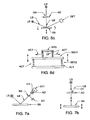
- FIG. 6 a is included to show a system suited to practicing a similar purpose as is the present invention, and which is Claimed in other Applications by the same Inventor herein.
- FIG. 6 b shows a prior art approach to providing a vertically oriented beam to a sample.
- FIG. 6 c shows a system which can be applied to provide a signal allowing “X” and “Y” plane adjustment.
- FIG. 6 d shows that the Stage (STG) for supporting a sample can be comprised of two Sections.
- FIGS. 6 ea - 6 ec shows a translational effect caused by tipping a sample.
- FIG. 6 ed demonstrates an irregular sample surface.
- FIG. 7 a shows a system which can be applied to provide a signal allowing “Z” distance adjustment.
- FIG. 7 b shows a system which can be applied to provide a signal allowing “X”-“Y” tip/tilt adjustment.
- FIG. 8 shows demonstrates a present invention ellipsometer system situated on “X”-“Y” control means above a large sample.
- FIG. 9 demonstrates a present invention ellipsometer system situated on “X”-“Y” control means above a large sample, including a system for flowing purging gas onto a sample.
- FIG. 10 shows a Front View of a Conventional Ellipsometer, Polarimeter or Reflectometer System with an Electromagnetic Beam shown approaching and reflecting from a sample system at an (AOI) of, for instance, 75 degrees.
- AOI AOI
- FIG. 11 shows that the (AOI) is changed to, for instance, 60 degrees when a Present Invention System ( 1 ) is placed in the pathway of the Electromagnetic Beam.
- FIG. 12 a shows a Side View of Present Invention System(s) (S 1 ) (S 2 ) (S 3 ) mounted on a Guide (G) upon which they can be slid right and left.
- Present Invention System (S 1 ) is shown slid into position to intercept Electromagnetic Beam (E).
- FIG. 12 b shows a Side View of the system shown in FIG. 3 a with Present Invention System(s) (S 1 ) (S 2 ) (S 3 ) slid to the right therein such that none thereof intercepts Electromagnetic Beam (E).
- S 1 Present Invention System(s)
- S 2 S 2
- S 3 Electromagnetic Beam
- FIG. 13 shows Multiangle Prisms (MAP) comprise a disclosed invention electromagnetic beam intercepting angle-of-incidence changing system on right and left sides thereof.
- MAP Multiangle Prisms
- FIG. 14 a shows how a Multiangle Prism (MAP) changes the pathway of an Electromagnetic Beam by Total Internal Reflection therewithin.
- MAP Multiangle Prism
- FIG. 14 b shows how a plurality of Mirrors can change the pathway of an Electromagnetic Beam by Reflection therefrom.
- FIG. 14 c shows additional configurations of Multiple Angle Prisms (MAP 1 ) and (MAP 2 ) which have Shutters (SH 1 ) & (SH 2 ), and (SH 3 ) & (SH 4 ) respectively present thereupon.
- FIG. 14 d shows FIG. 14 c with door shutters (D 1 ), (D 2 ), (D 3 ) and (D 4 ) present therein.
- FIG. 14 e shows a system for providing multiple angles-of-incidence utilizing Beam Splitter, Reflective means and shutter doors.
- FIG. 14 f system is, however, identified as a particularly relevant way to use reflective means to alter the trajectory of a Beam of electromagnetic Radiation, without significantly changing the phase angle between orthogonal components thereof.
- FIG. 15 shows a side elevational view of an adjustable mounting means for a Multiangle Prism (MAP), and optionally an Optical Lens (OL).
- MAP Multiangle Prism
- OL Optical Lens
- FIG. 16 shows a more detailed presentation of an ellipsometer system to which the Present Invention is applied.
- FIG. 17 a shows an approach to mounting Ellipsometer Polarization State Generator and Polarization State Analyzer Systems which allow easily changing the Angle-Of-Incidence of a Beam of Electromagnetic radiation caused to impinge on a Sample, as well as easily change the vertical height of thereof above the Sample.
- FIG. 17 b shows a modified version of the system of FIG. 17 a.
- the present disclosure is of new systems and methodology for alignment of both tilt, and vertical positioning of samples in ellipsometer and the like systems, which are well suited for automated operation.
- sample tip/tilt and height adjustments can be conducted using an electromagnetic beam which is caused to impinge on a sample at an oblique angle of incidence, (see FIG. 7 a ), perhaps in an itterative manner, a more convenient approach involves adjusting tip/tilt using a beam directed to be incident on a sample along a normal to the surface thereof, and reflect into a multiple element (eg. Quad-detector). Adjustment of tip/tilt in such an arrangement can be conducted to the point that equal signals are provided from each element of the multiple elements, which indicates that the sample surface is facing directly upward. Adjustment of the height of the sample can not be achieved by use of a normally directed beam, however, as the beam directed at normal incidence is insensitive to height.
- a beam directed to approach the sample at an oblique angle of incidence (eg. an ellipsometer beam) is best suited to use in adjusting the height of the sample.
- the method of adjustment can involve monitoring the output of a data detector and adjusting sample height until it peaks, or can involve use multiple element detectors and monitoring the output from each of the elements until they are equal, (again see FIG. 7 a elements (DET) and (AD) respectively).
- two sources eg. see FIG. 6 c (LS) and (LS′)
- electromagnetic beams of electromagnetic radiation can be applied to effect, respectively, tip/tilt and height locationing of samples, an approach which utilizes a single source thereof, (eg. see FIGS. 1-5 ), combined with beam splitters/director and the like, offer utility.
- a first sample alignment system embodiment comprises:
- a second sample alignment system embodiment comprises:
- LS source of electromagnetic radiation
- BS beam splitter
- Said beam splitter (BS) is positioned to direct a first portion of a beam of electromagnetic radiation from said source (LS) thereof normal onto said sample (S) and a second portion thereof toward said first mirror (M 21 ) which reflects it onto said sample (S) at an oblique angle such that it impinges thereupon at substantially the same location at which the first portion of said beam impinges.
- Said first portion of said beam after normally reflecting from said sample (S) is directed back along the path of its incidence, through said beam splitter (BS) and toward said alignment detector (QD 22 ).
- Said second portion of said beam after obliquely reflecting from said sample (S), is directed to reflect from said second mirror (M 22 ) toward said alignment detector (QD 22 ).
- Said first shutter (S 1 ) is in the pathway of said beam which passes through said beam splitter (BS) toward said alignment detector (QD 22 ), and said second shutter (S 2 ) is in the pathway of said beam which reflects from said second mirror (M 22 ).
- said shutters (S 1 ) (S 2 ) are operated to sequentially allow entry into said alignment detector (QD 22 ) of electromagnetic radiation:
- a third sample alignment system embodiment comprises:
- LS source of electromagnetic radiation
- BS beam splitter
- Said beam splitter (BS) is positioned to direct a first portion of a beam of electromagnetic radiation from said source (LS) thereof normal onto said sample (S) and a second portion thereof toward said first mirror (M 31 ) which reflects it onto said sample (S) at an oblique angle such that it impinges thereupon at substantially the same location at which the first portion of said beam impinges.
- Said first portion of said beam after normally reflecting from said sample (S) is directed back along the path of its incidence, through said beam splitter (BS) and normally toward said sample and after reflection therefrom toward said alignment detector (QD 33 ).
- Said second portion of said beam, after obliquely reflecting from said sample (S), is directed to reflect from said second mirror (M 32 ) toward said alignment detector (QD 33 ).
- Said first chopper (CHP 1 ) is in the pathway of said beam which passes through said beam splitter (BS) toward said alignment detector (QD 33 )
- said second chopper (CHP 2 ) is in the pathway of said beam which passes through the beam splitter (BS) toward the first mirror (M 31 ), and after being directed thereby to obliquely reflect from said sample (S), being directed to reflect from said second mirror (M 32 ) toward said alignment detector (QD 33 ).
- choppers (CHP 1 ) and (CHP 2 ) are operated at different frequencies which are distinguishable by the alignment detector (QD 33 ). It is noted that the choppers (CHP 1 ) and (CHP 2 ) can be placed in any functional location in the relevant beam path way.
- a forth sample alignment system embodiment comprises:
- FIG. 5 shows that a common source (LS) can be applied to provide both an ellipsometer beam and an alignment beam.
- LS common source
- FIG. 5 shows that a common source (LS) can be applied to provide both an ellipsometer beam and an alignment beam.
- the alignment detector can be a multi-element detector, (eg. a Quad Detector), or can be a detector which comprises a two dimensional plurality of detection elements arranged in an array.
- the systems just disclosed can be beneficially applied in ellipsometer systems which sequentially comprise a source of a beam of electromagnetic radiation, polarizer means for imposing a state of polarization on said beam, a stage for supporting a sample, analyzer means for selecting polarization states of a beam of electromagnetic radiation after it interacts with a sample placed on said stage, and an ellipsometer detector.
- the disclosed invention systems can be conveniently applied in automatic means for aligning the sample, wherein signals from the appropriate alignment or data detector(s) are used to control the vertical position and tilt of a sample.
- an ellipsometer arranged to provide a beam to the sample can be operated in ambient light instead of in a darkened environment. This can be an advantage in convenience.
- FIG. 6 a is included to show a system suited to practicing a similar purpose as Claimed in other Applications by the same Inventor herein, and FIG. 6 b shows a prior art approach to providing a vertically oriented electromagnetic beam onto a sample.
- FIG. 6 a shows a Source (BBS) which provides an alignment beam (IB) to the surface of a Sample (S) along an essentially perpendicular locus via a Lens (L) a Beam Splitter (BS 2 ), and Reflecting means (RM), Lens (L 3 ) and Beam Splitter (BS 1 ).
- BSS Source
- IB alignment beam
- the reflected beam makes its way back along the sequence of elements just recited but proceeds through Beam Splitter (BS 2 ) and into Camera (CCD 2 ) which provides signal to Monitor (M 2 ).
- Sample (S) tip/tilt can be adjusted by observing Monitor (M 2 ).
- the Camera (CCD 1 ), via Monitor (M 1 ) provides a visual indication of the Sample (S) as lit by Light Source (LEDS) positioned under the Beam Splitter (BS 1 ).
- LEDS Light Source
- FIG. 6 a system shows a Quad Detector (QD) positioned to intercept a portion of a Beam (EO′) of electromagnetic radiation provided by an Ellipsometer Polarization State Generator (PSG) as Beam (EI), via Beam Splitter (BS 3 ) after is reflects from the Sample (S) and proceeds otherwise to Polarization Stage Detector (PSD) as Beam (EO′′).
- PSG Ellipsometer Polarization State Generator
- BS 3 Beam Splitter
- signals from the Quad Detector (QD) indicate the relative vertical positioning of a Sample (S) surface, the tilt/tip of which is adjusted by use of Beam (IB) as described.
- IB Polarization Stage Detector
- the FIG. 6 a system can be applied in the system of the present invention.
- Stage (STG) can be fitted with Actuators (ACT), which are provided signals from effective Alignment Detectors (ie. (CCD 2 ) and (QD)), and which respond thereto by automatically adjusting Sample (S) tip/tilt and vertical height in a feedback loop.
- ACT Actuators
- FIG. 6 c shows a configuration of an Alignment Detector which provides sensitivity to Sample Rotations, but not Vertical Height.
- FIG. 7 a shows a configuration of an Alignment Detector (AD) which provides sensitivity to Sample Vertical Height.
- CH Central Hole
- AD′ Alignment Detector
- FIG. 7 b shows a system which can be applied to provide a signal allowing “X”-“Y” tip/tilt adjustment.
- the Alignment Detector comprises multiple detector elements distributed circumferentially about said Central Hole (CH), when signals from each are zero or approximately equal, the Sample (SS) will be properly aligned in “X”-“Y” tip/tilt directions. (Note, the signals from the multiple detector elements need not be equal, but can be reference values which are associated with proper alignment.
- FIG. 6 d shows that the Stage (STG) for supporting a sample is comprised of two Sections, the First Section (SEC 1 ) being comprised of means for adjusting a sample location in two dimensions, and the Second Section (SEC 2 ) being comprised of means for moving the first section in a height and tip/tilt dimension.
- the First Section (SEC 1 ) is adjusted, such that a desired location of a surface of a sample placed on said Stage (STG) moves in a plane which is parallel to that of a plane formed by the two dimensions in which First Section (SEC 1 ), movement is possible, (ie. to the left and right or in and out of the paper), said positioning being locked-in once achieved.
- the Second Section (SEC 2 ) is applied to orient a surface of a sample placed on the First Section (SEC 1 ) with respect to an Ellipsometer Beam, (see (LB) in FIG. 6 c for instance), perhaps by adjusting screws at the corners of the Second Section (SEC 2 ).
- the result is that the Second Section (SEC 2 ) allows adjustment of the “Z” height of a surface of a sample and the tip/tilt orientation of the plane in which said first section causes movement of said sample.
- the plane in which the First Section (SEC 1 ) causes the surface of a sample to move with respect to an electromagnetic beam (LB), provides that the plane of incidence which includes both a perpendicular to the sample surface and the locus of said electromagnetic beam projects perpendicular to the sample surface.
- FIGS. 6 ea - 6 ec are included to demonstrate a translational effect of tipping a sample, regarding the spot on a sample (S) where an oblique angle-of-incidence (O′) beam reflects therefrom.
- the incident Beam (EI) approaches the Sample (S) and reflects from Spot (x) on the surface thereof.
- FIG. 6 eb shows the Sample (S) tipped (TIP) to orient the normal to the surface of the sample vertically so that the angle-of-incidence is (O), and that the incident Beam (EI) reflects from a spot removed from the original Spot (x).
- a preferred embodiment of the present invention includes automated actuator means for effecting a coordinated translation when a tipping of a sample is effected. Note that an actual application of the demonstrated effect will typically not involve an entire Sample (S) being at an angle (O′), but rather will involve a Sample (S) with an irregular surface as demonstrated in FIG. 6 ed , wherein a Spot to be investigated does not have a vertically projecting normal without an effected tipping thereof.
- AD Adjustment Detectors
- Actuators which are applied to a Stage, such as demonstrated in FIG. 6 d , to automatically position a sample, (in “X”, “Y” and “Z” directions), and to adjust sample tip/tilt thereof.
- the actuators can be demonstratively visualized as any means for causing movement to the left/right and in/out and up/down on the page as regards the First Section (SEC 1 ), and for adjusting sample (SS) tip/tilt via the Second Section (SEC 2 ).
- FIGS. 8 and 9 are presented as the scope of the present invention includes use of ellipsometers which can be moved with respect to a stationary sample.
- FIG. 8 shows demonstrates a present invention ellipsometer system (SYS) situated on “X”-“Y” control means above a large sample (S). Indicated in block form are (LS) and (P), and (A) and (DET). A Cable is shown which can be used to provide power to, and transmit data from the ellipsometer system (SYS).
- FIG. 9 is similar to FIG. 8 , but has means added for flowing purging gas onto a sample at the point it is being investigated, during a period in which UV and IR wavelength Electromagnetism interacts therewith. As regards FIGS. 8 and 9 , in use the system selected from the group consisting of:
- FIGS. 10-16 describe Angle-of-Incidence changing systems and FIGS. 17 a and 17 b demonstrate an alternative system for achieving a similar effect.
- FIG. 10 shows a Front View of a Material System Investigating System, (eg. Ellipsometer, Polarimeter, Reflectometer or Spectrophotometer System), with an Electromagnetic Beam shown approaching and reflecting from a Sample System (SS) at an (AOI) of, for instance, 75 degrees with respect to normal.
- FIG. 11 shows that the (AOI) is changed to, for instance, 60 degrees with respect to normal when a disclosed invention electromagnetic beam intercepting angle-of-incidence changing system ( 1 ) is placed in the pathway of the Electromagnetic Beam.
- FIG. 12 a shows a Side View of a disclosed invention electromagnetic beam intercepting angle-of-incidence changing system mounted on a Guide (G) upon which they can be slid right and left.
- G Guide
- FIGS. 12 a and 12 b show that a sliding motion to the left will place a disclosed invention electromagnetic beam intercepting angle-of-incidence changing system (S 1 ) (S 2 ) (S 3 ) in the pathway of an Ellipsometer System Electromagnetic Beam (E), (see FIG. 12 a ), and sliding disclosed invention electromagnetic beam intercepting angle-of-incidence changing system to the right moves them out of the Electromagnetic Beam, (see FIG. 12 b ).
- FIGS. 12 a and 12 b correspond to a perpendicular to the plane of the surface of the paper in FIGS. 10 and 2 .
- FIG. 13 shows a Multiangle Prism (MAP) in a disclosed invention Electromagnetic Beam (E) intercepting Angle-of-Incidence changing system ( 1 ), on the left side thereof, (as indicated (BD) in FIG. 12 ). Note that the orientation of the (MAP) increases the (AOI) in FIG. 13 , whereas in FIGS. 12 , (and 14 a ), the (MAP) is oriented to decrease the (AOI).
- FIG. 14 a shows how a Multiangle Prism (MAP) changes the pathway of an Electromagnetic Beam by Total Internal Reflection therewithin.
- the shapes and materials which characterize the prisms can be designed and selected to cause the (desired (AOI) change, as well as effect phase shifts entered by total internal reflections to be stable, or at least have small sensitivity to changes in (AOI).
- Polymer for Far IR, Silicon or Germanium for IR, and Quartz for UV, VIS-NIR or CaF for VUV, for instance, can be utilized.
- a two or more Multiangle Prisms can be present on at least one side of the sample system, to provide an (AOI) not possible where only one is present.
- FIG. 14 b shows a plurality of mirrors (M) (M′) can also form disclosed invention electromagnetic beam intercepting angle-of-incidence changing system.
- M′ mirrors
- Optional Lenses can be positioned to focus a beam of electromagnetic radiation onto a spot on a sample system.
- Said Optional Lenses (OL) can be independently mounted, or affixed to the Multiangle Prisms (MAP). Note, it is possible to have two “Present Invention Systems” which provide the same AOI, one having Optional Lenses for focusing present, and the other not.
- FIGS. 14 c and 14 d show additional configurations of Multiple Angle Prisms (MAP 1 ) and (MAP 2 ) which have Shutters (SH 1 ) & (SH 2 ), and (SH 3 ) & (SH 4 ) respectively present thereupon.
- Said Shutters (SH 1 ) & (SH 2 ), and (SH 3 ) & (SH 4 ) can be, for instance, voltage controlled liquid crystals or electromagnetic-optics means for effectively changing the refractive index of the top and bottom surfaces of a multi-angle prism, for the purpose of controlling the internal reflection/transmission properties.
- FIG. 1 Multiple Angle Prisms
- MAP 2 Multiple Angle Prisms
- SH 3 ) & (SH 4 ) can be, for instance, voltage controlled liquid crystals or electromagnetic-optics means for effectively changing the refractive index of the top and bottom surfaces of a multi-angle prism, for the purpose of controlling the internal reflection/transmission properties.
- FIG. 14 c shows Input Electromagnetic Beam (EMB 1 ) entering Multi-Angle Prism (MAP 1 ) and interacting with the interface between said Multi-Angle Prism (MAP 1 ) and said Shutter (SH 1 ). If said interface is substantially transmissive then Beam (EA) proceeds to the Sample System, and reflects therefrom at point (P). Said Beam (EA) then proceeds through Multi-Angle Prism (MAP 2 ) and exits therefrom as Output Electromagnetic Beam (EMB 2 ). If, however, the interface between said Multi-Angle Prism (MAP 1 ) and said Shutter (SH 1 ) is substantially reflective, it should be appreciated that Input Electromagnetic Beam (EMB 1 ) will reflect thereat and become beam (EB).
- EMB 1 Input Electromagnetic Beam
- FIG. 14 d shows FIG. 14 c with additional Physical Door-Shutter means (D 1 ), (D 2 ), (D 3 ) and (D 4 ) in place to further enhance the Transmission/Reflection effect described with respect to FIG. 14 c .
- MAP 1 Multi-Angle Prism
- SH 1 Shutter
- D 2 Physical Door-Shutter
- D 1 Physical Door-Shutter
- Said Physical Door-Shutter means (D 1 ), (D 2 ), (D 3 ) and (D 4 ) must, of course, be coordinated with operation of Shutters (SH 1 ) & (SH 2 ), and (SH 3 ) & (SH 4 ), but when present serve to essentially completely overcome the effect of any imperfect operation of Shutters (SH 1 ) & (SH 2 ), and (SH 3 ) & (SH 4 ).
- FIG. 14 e shows an alternative system for effecting different angles of incidence.
- a Beam Splitter receives a Beam of Electromagnetic Radiation (EM) and continuously reflects approximately half (EB) and transmits (EA) the remainder.
- the reflected portion (EB′) reflects from a Second Reflection means (R 2 ).
- Both the reflected (EB′) and Transmitted (EA) Electromagnetic Beams arrive at the same point on Sample System (SS), but at different angles-of-incidence.
- SS Sample System
- Door Shutters D 5 ) and (D 6 ) are present, and are operated to block one or the other of (EA) and (EB′) when desired.
- Said 818 Patent describes a Beam Folding Optics System which serves to direct an electromagnetic beam via multiple reflections, without significantly changing the phase angle between orthogonal components therein. Briefly, two pairs of mirrors are oriented to form two orthogonally related planes such that the phase shift entered to an electromagnetic beam by interaction with the first pair of mirrors is canceled by interaction with the second pair.
- the Reflector (R 2 ) in FIG. 14 e (and a similar Reflector in an output side) can comprise Patent 818 Beam Folding Optics.
- FIG. 5 from said 818 Patent is reproduced herein as FIG. 14 f .
- the disclosed invention system can also include means for adjusting, for instance, tilt, translation and rotation orientations of the multi-angle prisms and/or the Optional Lenses (OL) within the containing structure.
- Such presence facilitates easy system set-up optimization.
- FIG. 15 demonstrates mounting Bases (B 1 ), (B 2 ) and (B 3 ) mounted with respect to one another so that mounting Base ( 2 ) can move right and left on mounting Base ( 1 ), and so that mounting Base ( 3 ) can rotate on mounting Base ( 2 ).
- a Multiangle Prism (MAP) is shown mounted to mounting Base ( 3 ).
- Mounting Base ( 1 ) can of course be mounted in a Present Invention Electromagnetic Beam (E) intercepting Angle-of-Incidence (AOI) changing system ( 1 ), as shown in FIG. 12 , in the position of (BD) or (BD′) in a manner to allow it Rotational or any Linear Degrees of Motion Freedom. In particular motion into and out of the plane of the paper is also possible at the (B 1 ), (B 2 ) and/or (B 3 ) level, as required.
- an Optical Lens (OL) is also shown rotatably and translatably mounted via mounting Base (B 4 ) to mounting Base ( 1 ). This is an optional feature, and it is noted that the Optical Lens (OL) can be absent, or separately mounted.
- FIG. 15 is to be considered only demonstrative, and functional mountings can include any required translation, tilt and rotation adjustment capability shown, and not directly shown or visible in the view presented.
- Electromagnetic Beam which interacts with a Sample System (SS) will often be polarized, where the disclosed invention system ( 1 ) is used with a Reflectometer System, this need not be the case.
- Reflectometers which produce unpolarized electromagnetic radiation and cause impingement at oblique (AOI's), (instead or in addition thereto ellipsometer produced beams), can have the disclosed invention applied thereto as well.
- FIG. 16 provides a general elemental configuration of an ellipsometer system ( 10 ) which can be applied to investigate a sample system (SS). Shown are, sequentially:
- input (AC 1 ) and output (AC 2 ) additional elements eg. multiangle prisms or functional equivalents as represented by (BD) and (BD′) in FIG. 12
- additional elements eg. multiangle prisms or functional equivalents as represented by (BD) and (BD′) in FIG. 12
- BD multiangle prisms or functional equivalents as represented by (BD) and (BD′) in FIG. 12
- a separate step, utilizing a sample system for which retardation can be modeled by a parameterized equation, allows evaluation of the parameters in parametric equations for the “in-plane” components of windows separately.
- Work reported in the literature by other researchers provided equations which corrected only first order effects, and said equations have proven insufficient to correct for large, (eg. six (6) degrees), of retardation which is typical in standard vacuum chamber windows and which can occur in disclosed invention (AOI) changing systems.
- AOI invention
- shutters (SH 1 ) (SH 2 ) (SH 3 ) (SH 4 ) and shutter doors (D 1 ) (D 2 ) (D 3 ) (D 4 ) (D 5 ) (D 6 ) (D 5 ′) (D 6 ′) can be of any functional type, such as mechanical or voltage driven liquid crystal devices.
- FIGS. 17 a and 17 b show a mechanical system for mounting a Reflectometer or Spectrophotometer Source and Detector, or Ellipsometer or Polarimeter Polarization State Generator, (eg. Source, Polarizer and optionally compensator), and Polarization State Analyzer, (eg. optional Compensator, Analyzer and Detector), Systems.
- Said approach to mounting allows easily changing the Angle-Of-Incidence of a Beam of Electromagnetic radiation caused to impinge on a Sample.
- Said system for setting the angle of incidence of a beam (E) of electromagnetic radiation comprises, as viewed in elevation, First (FA) and Second (SA) arms pivotally interconnected to one another at an upper aspect thereof by a First Pivot Means (FPM), said first (FA) and second (SA) arms projecting downward and to the left and right of said First Pivot Means (FPM); distal ends of said First (FA) and Second (SA) arms being pivotally affixed to Third (TA) and Forth (FA) arms, said Third (TA) and Forth (FA) arms being pivotally interconnected to one another by Second Pivot Means (SPM) at a lower aspect thereof, said Third (TA) and Forth (FA) arms being projected upward and to the left and right of said Second Pivot Means (SPM) at said lower aspect thereof; there being at least two pivotally affixed substantially Downward Projecting Arms (DPA) to each of said Third (TA) and Forth (FA) arms, distal ends of which are pivotally a
- a Sample located such that a Beam (E) of electromagnetic radiation produced by said Source (LS) of a beam of electromagnetic radiation reflects from an upper surface of said Sample (SS) and enters said detector of said beam of electromagnetic radiation, such that in use when the First Pivot Means (FPM) at which said First (FA) and Second (SA) arms are interconnected is caused to be vertically raised or lowered, the angle of incidence at which the Beam (E) of electric radiation approaches said sample surface is changed, but the location at which it interacts with said Sample (SS) surface remains substantially unchanged.
- FPM First Pivot Means
- designators (E), (EM), (EMB 1 ), (EMB 2 ) in the various Figures all identify a Beam of Electromagnetic Radiation from a Source (LS) thereof.
- Reflectometer Spectrophotometer Ellipsometer, Polarimeter, Mueller Matrix Measuring System and the like systems can be generically termed “material system investigating systems”.
- focusing optics is used in the Claims to indicate that any optics, lens or mirror, can be applied to focus and/or re-collimate an electromagnetic beam.
- the present invention is unique in many respects, but is definitely new, novel and non-obvious in teaching the use of focused beams which are caused to approach a sample along an oblique angle of incidence to align the vertical position of said sample in an ellipsometer or the like system, followed by removal of the focusing means prior to acquiring data.
- the present invention teaches that focusing an oblique angle of incidence beam onto a sample improves the sensitivity to the vertical positioning of said sample and allows more precise vertical positioning, but that it is not always preferable to then acquire data with the focusing means in place.
- the present invention provides for easily providing focusing, or not, of a beam at a single angle of incidence, at least one angle-of-incidence.
Abstract
Description
TAN(ψ)e (iΔ) =r p /r s
-
- a sample supporting stage which can be translated in “X”, “Y” or “Z” directions as well as rotated about “X”, “Y” and optionally “Z” axes;
- vertically above said stage there being a first beam splitter means, a lens and a first camera means for providing a view of a portion of the surface of said sample, said first beam splitter means optionally having positioned on a lower surface thereof light emitting means for providing light to the surface of said sample;
- laterally with respect to said first beam splitter means there being a reflection means;
- vertically above said reflection means there being a second beam splitter;
- vertically above said second beam splitter there being a second camera means and laterally with respect to said second beam splitter, there being sequentially a lens and an essentially point source of electromagnetic radiation;
- said first and second camera means each having associated therewith display means.
- Said system further comprises an ellipsometer polarization state generator to cause, and a polarization stage detector to monitor, a beam of electromagnetic radiation which in use impinges on said monitored location on said surface of said sample at an oblique angle thereto.
- In use said first camera means and its associated display means provide a view of at least a portion of the surface of a sample utilizing light provided by said light emitting means for providing light to the surface of said sample positioned on said lower surface of said first beam splitter, and said essentially point source of electromagnetic radiation provides electromagnetic radiation to the surface of said sample via said second beam splitter, said reflective means and said first beam splitter, and said sample supporting stage is caused to be translated in any of said “X”, “Y” and “Z” directions as well as rotated about said “X”, “Y” and optionally “Z” axes which are necessary to cause an interrogating beam of electromagnetic radiation provided by said essentially point source of a source of electromagnetic radiation to reflect from the surface of said sample, proceed back through said first beam splitter means, reflect from said reflective means, pass through said second beam splitter means, enter said second camera means and cause an image on the display means associated therewith which indicates that the monitored location on the sample surface is oriented so as to face substantially vertically.
- The purpose of the foregoing is to align said sample surface to assure that said beam of electromagnetic radiation provided to said monitored location on the surface of said sample at an oblique angle approaches said surface at known intended angle of incidence and plane of incidence orientation, rather than at an angle of incidence and plane of incidence orientation which is modified by surface irregularities or non-flat samples.
Said system can further comprise a polarizer means in the path of said beam of electromagnetic radiation provided by said essentially point source of electromagnetic radiation, and in which said first beam splitter is sensitive to polarization state, and the polarizer means can be adjustable to enable control of the direction of polarization. The system point source of a source of electromagnetic radiation can comprise a fiber optic.
-
- a system for orienting a sample on a stage in an ellipsometer system comprising a first light source, a polarizer, said stage, an analyzer and a detector;
- said system further comprising a detection system having a second light source, wherein said detection system is independently adjustable in relation to said ellipsometer, and wherein said detection system can be electronically locked into position relative to said ellipsometer so that said ellipsometer and said detection system can be adjusted as one unit in relationship to said stage, wherein said detection system can detect both a tilt of a sample placed onto said stage, and a distance of said sample from a coordinate source of the ellipsometer in two perpendicular axes; and
- said system further comprising an adjusting device, wherein said adjusting device can adjust tilt of said stage, and wherein said adjusting device can adjust the position of said ellipsometer and detection system when in an electronically locked relationship with respect to one another.
-
- Patent to Coates U.S. Pat. No. 4,373,817;
- Patent to Coates U.S. Pat. No. 5,045,704;
- RE. 34,783 to Coates;
- Patent to Mikkelsen et al., U.S. Pat. No. 6,600,560;
- Patent to Fanton et al., U.S. Pat. No. 5,596,411;
- Patent to Piwonka-Corle et al., U.S. Pat. No. 5,910,842;
- Patent to Piwonka-Corle et al., U.S. Pat. No. 5,608,526;
- Patent to Bareket, U.S. Pat. No. 5,889,593;
- Patent to Norton et al., U.S. Pat. No. 5,486,701;
- Patent to Aspnes et al., U.S. Pat. No. 5,900,939;
- PCT Application Publication WO 99/45340;
- Published Application of Stehle et al., No. US2002/0024668 A1.
-
- an ellipsometer source of a beam of electromagnetic radiation;
- a stage for supporting a sample and having means for effecting tip/tilt and translation thereof;
- a data detector of electromagnetic radiation;
and which method comprises:
said method then optionally further comprising:
-
- source of a beam of spectroscopic electromagnetic radiation;
- stage for supporting a sample;
- data detector of spectroscopic electromagnetic radiation; and
- between said source and stage, means for receiving a beam of spectroscopic electromagnetic radiation from said source thereof and providing it to a surface of a sample on said stage at any of at least two angles-of-incidence with respect to said surface, with at least one of said angles-of-incidence being available as a focused, and as a non-focused, beam onto said sample surface.
Said source of a beam of spectroscopic electromagnetic radiation, data detector of spectroscopic electromagnetic radiation, and means for receiving a beam of spectroscopic electromagnetic radiation from said source thereof and providing it to a surface of a sample on said stage at any of at least two angles-of-incidence with respect to said surface, are functionally mounted so as to enable movement as a unit.
Said system further comprises means for detecting the direction in which a normal to a sample surface projects and means for detecting the angle and plane of incidence of a beam of electromagnetic radiation provided by said source of a beam of spectroscopic electromagnetic radiation, and providing signals which are representative thereof.
Said system further comprises actuator means for receiving said representative signals and in response automatically controlling the separation between: - as a unit, said source, data detector, and means for receiving a beam of spectroscopic electromagnetic radiation from said source thereof and providing it to a sample on said stage; and
- the surface of a sample on said stage; and
- actuator means for receiving said representative signals and in response automatically controlling the effective tip/tilt between said beam of electromagnetic radiation provided by said source of a beam of spectroscopic electromagnetic radiation with respect to said sample surface, and therefor the orientation of the angle and plane of incidence of said spectroscopic beam of electromagnetic radiation provided by said source of a beam of spectroscopic electromagnetic radiation with respect to said sample surface.
Optionally, said system can comprise means for causing rotation of said sample about a normal to said surface thereof.
Said system can further comprise between said stage and detector, means for receiving a beam of spectroscopic electromagnetic radiation reflected from said sample and providing it to said detector in any of at least two angles-of-incidence with respect to said surface, with at least one of said angles-of-incidence being available as a focused, and as a non-focused, beam onto said sample surface.
Said system can further comprise a polarizer between said source of a beam of spectroscopic electromagnetic radiation said stage, and an analyzer between said stage and said detector, and in which said system is an ellipsometer or polarimeter.
It is noted that actuator action can be arranged to causes a normal to the sample surface at the point at which said beam of spectroscopic electromagnetic radiation impinges, to project substantially vertically upward in laboratory coordinates.
-
- a source of a beam of spectroscopic electromagnetic radiiation;
- a stage for supporting a sample;
- a data detector of spectroscopic electromagnetic radiation; and
- between said source and stage, means for receiving a beam of spectroscopic electromagnetic radiation from said source thereof and providing it to the surface of a sample on said stage at any of at least two angles-of-incidence with respect to said surface, with at least one of said angles-of-incidence being available as a focused, and as a non-focused, beam onto said sample surface.
- Said system is characterized by at least one selection from the group consisting of:
- said stage for supporting said sample comprises means for moving said sample in two orthogonal directions in a plane substantially parallel to said sample surface and/or in a direction substantially perpendicular thereto; and
- the presence of means for moving, as a group,
- said source;
- data detector; and
- means for receiving a beam of spectroscopic electromagnetic radiation from said source thereof and providing it to a sample on said stage;
- in two orthogonal directions in a plane substantially parallel to said sample surface and/or in a direction substantially perpendicular thereto.
Said system can further comprising: - means for controlling stage tip/tilt and therefor the orientation of the plane in which said sample surface is present; and
- means for causing rotation of said sample.
The stage for supporting a sample in said system can comprise two sections: - the first section being comprised of means for adjusting a sample location in two dimensions substantially parallel to the surface of said sample, and
- the second section being comprised of means for moving the first section in a direction to place said first section closer to or further away from said source, data detector and said means for receiving a beam of spectroscopic electromagnetic radiation from said source thereof and providing it to a sample on said stage, and for adjusting tip/tilt of the surface of said sample.
In use the first section of said stage can be applied to position a spot on a surface of a sample placed on said stage in a plane which is parallel to that of a plane formed by the two dimensions in which said first section can cause movement. The second section of said stage can be applied to orient said surface of a sample placed on the first section with respect to a beam of spectroscopic electromagnetic radiation provided by said source thereof via adjustment of the location of a surface of a sample along a direction generally perpendicular to said sample surface, and to control the tip/tilt orientation of the plane in which said first section of said stage causes movement of said sample. The plane in which the first section causes the surface of a sample to move with respect to an electromagnetic beam from said source thereof can thus orient the plane of incidence, which includes both a perpendicular to the sample surface and the locus of said spectroscopic electromagnetic, so that both project substantially perpendicular to the sample surface.
Again, said system can further comprise a polarizer between said source of electromagnetic radiation and said stage, and an analyzer between said stage and said data detector and in which said system is an ellipsometer or polarimeter.
Said system can further comprise means for providing an alignment beam of electromagnetic radiation provided by said source of a beam of spectroscopic electromagnetic radiation or an alternative source, and an alignment detector, said alignment detector being positioned to detect when said sample is oriented so that said alignment beam approaches said sample surface so that, at the point of reflection therefrom, it reflects directly back along its incident locus, the purpose being to enable align said sample surface in a known orientation.
Said system can further comprise, between said stage and detector, means for receiving a beam of spectroscopic electromagnetic radiation reflected from said sample and providing it to said detector in any of at least two angles-of-incidence with respect to said surface, with at least one of said angles-of-incidence being available as a focused, and as a non-focused, beam onto said sample surface.
-
- said spectroscopic electromagnetic beam; and
- said alignment beam;
to distinguish said at least one selection from external light, thereby enabling use in rooms illuminated by non-modulated light.
-
- stage for supporting a sample;
- data detector of spectroscopic electromagnetic radiation;
- said system further comprising, between said source and stage, means for receiving a beam of spectroscopic electromagnetic radiation from said source thereof and providing it to a surface of a sample on said stage at any of at least two angles-of-incidence with respect to said surface, with at least one of said angles-of-incidence being available as a focused, and as a non-focused, beam onto said sample surface;
-
- as a unit, said source, data detector, and means for receiving a beam of spectroscopic electromagnetic radiation from said source thereof and providing it to a sample on said stage; and
- the surface of a sample on said stage;
Said system can further comprise a polarizer between said source of a beam of spectroscopic electromagnetic radiation said stage, and an analyzer between said stage and said detector, and in which said system is an ellipsometer or polarimeter.
Said system can provide that the actuator action causes a normal to the sample surface at the point at which said beam of spectroscopic electromagnetic radiation impinges, to project substantially vertically upward in laboratory coordinates.
-
- c1) while monitoring the output signal from said data detector causing said stage to effect translation of said alignment sample so that said beam is directed to a second location thereon at said oblique angle, reflects therefrom and enters said data detector, followed by adjusting the tip/tilt of said stage;
- c2) while monitoring the output signal from said data detector causing said stage to effect translation of said alignment sample so that said beam is directed to a third location thereon at said oblique angle, reflects therefrom and enters said data detector, followed by adjusting the tip/tilt of said stage, said third location being other than co-linear with said first and second locations;
-
- c4) while monitoring the output signal from said data detector causing said stage to effect translation of said alignment sample so that said beam is directed to a forth location thereon at said oblique angle, reflects therefrom and enters said data detector, followed by adjusting the tip/tilt of said stage.
It is noted that where four locations are used the preferred approach is to position then as corners of a square oriented about a central region of the sample.
- c4) while monitoring the output signal from said data detector causing said stage to effect translation of said alignment sample so that said beam is directed to a forth location thereon at said oblique angle, reflects therefrom and enters said data detector, followed by adjusting the tip/tilt of said stage.
-
- e) providing and positioning a source of a beam of electromagnetic radiation derived from a selection from the group consisting of:
- said ellipsometer source of a beam of electromagnetic radiation; and
- an alternative source of a beam of electromagnetic radiation;
- such that it provides an alignment beam of electromagnetic radiation which proceeds substantially along an incident locus which is normal to said alignment sample, which then reflects from said alignment sample and returns substantially back along the incident locus; and
- providing a normal beam monitoring multi-detector element alignment detector so that it monitors said reflected alignment beam of electromagnetic radiation, and positioning it such that each detector element of said normal beam monitoring multi-detector element alignment detector provides no output signal or such that each detector element of said normal beam monitoring multi-detector element alignment detector provides reference output signals when said normally reflected alignment beam of electromagnetic radiation interacts therewith, said normal beam monitoring multi-element alignment detector being selected from the group consisting of:
- it comprises a plurality of detector elements surrounding a central hole through which said alignment beam passes, said detector elements being positioned to monitor said alignment beam after it reflects from said sample; and
- it comprises a plurality of detector elements in combination with a beam spliter, said beam spliter being positioned to intercept said beam which reflects from said sample and direct a portion thereof toward said alignment beam monitoring detector elements;
- f) removing said alignment sample from said stage and placing a second sample thereupon;
- g) adjusting the locations of said ellipsometer source of a beam of electromagnetic radiation and data detector and alignment detector, and/or the tip/tilt of said stage so that the normal beam monitoring multi-detector element alignment detector provides no output signals or such that each detector element of said normal beam monitoring multi-detector element alignment detector provides said reference output signals; and
- h) optionally simultaneous with adjusting the tip/tilt of said stage effecting translation thereof to maintain unchanged the location on said second sample at which said oblique beam reflects therefrom.
(Note, the reference signals in step e can all be zero, or any combination of zero and non-zero values, or can all be non-zero values which the alignment detector produces when the alignment sample is properly aligned. And, in step f, it is to be understood that while the preferred and simpler approach is to align the stage/sample by tip/tilt of the stage, it is possible to alternatively or in combination with effecting tip/tilt of the stage, move the locations of said ellipsometer source of a beam of electromagnetic radiation and data detector and alignment detector to accomplish said alignment).
- e) providing and positioning a source of a beam of electromagnetic radiation derived from a selection from the group consisting of:
-
- it comprises a plurality of detector elements surrounding a central hole toward which said beam is directed after it reflects from said sample; and
- it comprises a plurality of detector elements in combination with a beam spliter, said beam spliter being positioned to intercept said beam which reflects from said sample and direct a portion thereof toward said oblique beam monitoring multi-element alignment detector.
The method recited above remains the same, but signals from the plurality of elements of the oblique beam monitoring multi-element alignment detector of electromagnetic radiation are monitored, and the goal is to orient said stage so that the detector elements provide no output signals, or such that each detector element of said normal beam monitoring multi-detector element alignment detector provides reference output signals.
-
- the data detector signal is maximized; and
- the signals from the multiple elements of a multiple element alignment detector through which said beam is caused to pass or is reflected onto are essentially equal;
-
- the data detector signal is maximized; and
- the signals from the multiple elements of a multiple element detector through which said beam is caused to pass or is reflected onto are essentially equal.
Said steps b and c are itteratively repeated a plurality of times at a selection from the group consisting of: - the same location on the sample surface; and
- a plurality of locations on the sample surface;
to improve alignment.
Said method can further include providing feedback/actuator means; said feedback means being applied to receive at least one signal from at least one selection from the group consisting of: - said data detector; and
- said alignment detector;
and wherein said actuator means effects sample tilt/tip and/or sample raising or lowering in steps b and c by automatic response to said received at least one signal.
Importantly, said method can further comprises the step of:
-
- said source of a beam of spectroscopic electromagnetic radiation; and
- an alternative source a beam of electromagnetic radiation;
and an alignment detector can be present, with said alignment detector being positioned to detect when said sample is oriented so that said alignment beam approaches said sample surface so that, at the point of reflection therefrom, it reflects directly back along its incident trajectory, the purpose being to enable orienting said sample surface in a known orientation.
Said method can include applying a beam modulator to modulate at least one selection from the group consisting of: - said spectroscopic electromagnetic beam; and
- said alignment beam;
to distinguish said at least one selection from external light, thereby enabling use in rooms illuminated by non-modulated light in which the electromagnetic beam is modulated to distinguish it from external light, to enable use in lit rooms.
-
- source of a beam of spectroscopic electromagnetic radiation;
- stage for supporting a sample;
- data detector of spectroscopic electromagnetic radiation;
- said system further comprising, between said source and stage, means for receiving a beam of spectroscopic electromagnetic radiation from said source thereof and providing it to the surface of a sample on said stage at any of at least two angles-of-incidence to said surface, with at least one of said angles-of-incidence being available as a focused and as a non-focused beam onto said sample surface;
- said system being characterized by at least one selection from the group consisting of:
- said system being characterized by at least one selection from the group consisting of:
- said stage for supporting said sample comprises means for moving said sample in two orthogonal directions in a plane parallel to said sample surface; and
- the presence of means for moving as a group, said source, data detector and means for receiving a beam of spectroscopic electromagnetic radiation from said source thereof and providing it to a sample on said stage, in two orthogonal directions in a plane substantially parallel to said sample surface;
- the presence of means for moving the sample in a direction to place it closer to or further away from said source, data detector, and said means for receiving a beam of spectroscopic electromagnetic radiation from said source thereof, and providing it to a sample on said stage;
- said system further comprising means for controlling stage tip/tilt and therefor the orientation of the plane in which said sample surface is present, and
- said system optionally further comprising means for causing rotation of said sample;
- said system further comprising means for providing an alignment beam of electromagnetic radiation provided by a selection from the group consisting of:
- said source of a beam of spectroscopic electromagnetic radiation; and
- an alternative source a beam of electromagnetic radiation;
and an alignment detector, said alignment beam and detector being oriented and positioned to detect when said sample is oriented and with a normal to its surface projecting such that said alignment beam approaches said sample surface and, at the point of reflection therefrom, reflects directly back upward along its incident trajectory, there being a known relationship between the loci of said alignment and said beam of spectroscopic electromagnetic radiation.
Said method proceeds with:
-
- the data detector signal strength is maximized; and
- signals from said second alignment detector indicate that the reflected beam is directed to substantially maximize data detector signal strength.
Steps b and c can be itteratively repeated a plurality of times at a selection from the group consisting of: - the same location on the sample surface; and
- a plurality of locations on the sample surface;
to improve alignment of said spectroscopic electromagnetic beam.
Effecting tilt/tip and sample raising or lowering in steps b and c can be effected by automatic systems which utilize feedback from said data detector and/or optionally, said alignment detectors.
Said method can further comprise the step of:
-
- an ellipsometer source of a beam of electromagnetic radiation;
- a stage for supporting a sample and having means for effecting tip/tilt and translation thereof;
- a data detector of electromagnetic radiation;
comprises the steps:
-
- c1) while monitoring the output signal from said data detector causing said stage to effect translation of said alignment sample so that said beam is directed to a second location thereon at said oblique angle, reflects therefrom and enters said data detector, followed by adjusting the tip/tilt of said stage;
- c2) while monitoring the output signal from said data detector causing said stage to effect translation of said alignment sample so that said beam is directed to a third location thereon at said oblique angle, reflects therefrom and enters said data detector, followed by adjusting the tip/tilt of said stage, said third location being other than co-linear with said first and second locations;
- c3) while monitoring the output signal from said data detector causing said stage to effect translation of said alignment sample so that said beam is directed to a said first location thereon at said oblique angle, reflects therefrom and enters said data detector, followed by adjusting the tip/tilt of said stage;
with the result being that the stage is oriented in tip/tilt so that no matter from what location on said alignment sample said beam is caused to reflect, the output from said data detector remains substantially the same.
Said method then optionally further comprises: - d) while monitoring the data detector output signal moving the location and orientation thereof until said output signal therefrom is substantially maximized.
Said method can which further comprise itteratively repeating a step c4 along with steps c1, c2 and c3, said step c4 being selected from the group consisting of c4a and c4b: - c4a) while monitoring the output signals from the detector elements of said oblique beam monitoring multi-element alignment detector, causing said stage to effect translation of said sample so that said beam is directed to a forth, arbitrary, location thereon at said oblique angle, reflects therefrom and enters said multi-element alignment detector, followed by adjusting the tip/tilt of said stage.
-
- e) providing and positioning a source of a beam of electromagnetic radiation derived from a selection from the group consisting of:
- said ellipsometer source of a beam of electromagnetic radiation; and
- an alternative source of a beam of electromagnetic radiation;
- such that it provides an alignment beam of electromagnetic radiation which proceeds substantially along an incident locus which is normal to said alignment sample, which then reflects from said alignment sample and returns substantially back along the incident locus; and
- providing a normal beam monitoring multi-detector element alignment detector so that it monitors said reflected alignment beam of electromagnetic radiation, and positioning it such that each detector element of said normal beam monitoring multi-detector element alignment detector provides no output signal or such that each detector element of said normal beam monitoring multi-detector element alignment detector provides reference output signals when said reflected alignment beam of electromagnetic radiation normally interacts therewith, said normal beam monitoring multi-element alignment detector being selected from the group consisting of:
- it comprises a plurality of detector elements surrounding a central hole through which said alignment beam passes, said detector elements being positioned to monitor said alignment beam after it reflects from said sample; and
- it comprises a plurality of detector elements in combination with a beam spliter, said beam spliter being positioned to intercept said beam which reflects from said sample and direct a portion thereof toward said alignment beam monitoring detector elements;
- f) removing said alignment sample from said stage and placing a second sample thereupon;
- g) adjusting the locations of said ellipsometer source of a beam of electromagnetic radiation and data detector and alignment detector, and/or the tip/tilt of said stage so that the normal beam monitoring multi-detector element alignment detector provides no output signals or such that each detector element of said normal beam monitoring multi-detector element alignment detector provides said reference output signals; and
- h) optionally simultaneous with adjusting the tip/tilt of said stage effecting translation thereof to maintain unchanged the location on said second sample at which said oblique beam reflects therefrom.
- e) providing and positioning a source of a beam of electromagnetic radiation derived from a selection from the group consisting of:
-
- an ellipsometer source of a beam of electromagnetic radiation;
- a stage for supporting a sample and having means for effecting tip/tilt and translation thereof;
- an oblique beam monitoring multi-element data detector of electromagnetic radiation;
comprises the steps:
-
- c1) while monitoring the output signal from said data detector causing said stage to effect translation of said alignment sample so that said beam is directed to a second location thereon at said oblique angle, reflects therefrom and enters said data detector, followed by adjusting the tip/tilt of said stage;
- c2) while monitoring the output signal from said data detector causing said stage to effect translation of said alignment sample so that said beam is directed to a third location thereon at said oblique angle, reflects therefrom and enters said data detector, followed by adjusting the tip/tilt of said stage, said third location being other than co-linear with said first and second locations;
- c3) while monitoring the output signal from said data detector causing said stage to effect translation of said alignment sample so that said beam is directed to a said first location thereon at said oblique angle, reflects therefrom and enters said data detector, followed by adjusting the tip/tilt of said stage;
with the result being that the stage is oriented in tip/tilt so that no matter from what location on said alignment sample said beam is caused to reflect, the output from said data detector remains substantially the same;
-
- c4a) while monitoring the output signals from the detector elements of said oblique beam monitoring multi-element alignment detector, causing said stage to effect translation of said sample so that said beam is directed to a forth, arbitrary, location thereon at said oblique angle, reflects therefrom and enters said multi-element alignment detector, followed by adjusting the tip/tilt of said stage.
- c4b) while monitoring the output signals from the detector elements of said oblique beam monitoring multi-element alignment detector, causing said stage to effect translation of said sample so that said beam is directed to a forth, location thereon at said oblique angle, reflects therefrom and enters said multi-element alignment detector, followed by adjusting the tip/tilt of said stage, said forth location being oriented so as to form a square shape with the first three locations.
And again said method can provide that said ellipsometer system further comprise a focusing lens between said ellipsometer source of a beam of spectroscopic electromagnetic radiation and said stage.
Said oblique beam monitoring multi-element alignment detector can be selected from the group consisting of: - it comprises a plurality of detector elements surrounding a central hole toward which said beam is directed after it reflects from said sample; and
- it comprises a plurality of detector elements in combination with a beam spliter, said beam spliter being positioned to intercept said beam which reflects from said sample and direct a portion thereof toward said oblique beam monitoring multi-element alignment detector.
Said method can further comprise: - e) providing and positioning a source of a beam of electromagnetic radiation derived from a selection from the group consisting of:
- said ellipsometer source of a beam of electromagnetic radiation; and
- an alternative source of a beam of electromagnetic radiation;
- such that it provides an alignment beam of electromagnetic radiation which proceeds substantially along an incident locus which is normal to said alignment sample, which then reflects from said alignment sample and returns substantially back along the incident locus; and
- providing a normal beam monitoring multi-detector element alignment detector so that it monitors said reflected alignment beam of electromagnetic radiation, and positioning it such that each detector element of said normal beam monitoring multi-detector element alignment detector provides no output signal or such that each detector element of said normal beam monitoring multi-detector element alignment detector provides reference output signals when said reflected alignment beam of electromagnetic radiation normally interacts therewith, said normal beam monitoring multi-element alignment detector being selected from the group consisting of:
- it comprises a plurality of detector elements surrounding a central hole through which said alignment beam passes, said detector elements being positioned to monitor said alignment beam after it reflects from said sample; and
- it comprises a plurality of detector elements in combination with a beam spliter, said beam spliter being positioned to intercept said beam which reflects from said sample and direct a portion thereof toward said alignment beam monitoring detector elements;
- f) removing said alignment sample from said stage and placing a second sample thereupon;
- g) adjusting the locations of said ellipsometer source of a beam of electromagnetic radiation and data detector and alignment detector, and/or the tip/tilt of said stage so that the normal beam monitoring multi-detector element alignment detector provides no output signals or such that each detector element of said normal beam monitoring multi-detector element alignment detector provides said reference output signals; and
- h) optionally simultaneous with adjusting the tip/tilt of said stage effecting translation thereof to maintain unchanged the location on said second sample at which said oblique beam reflects therefrom.
-
- reflectometer;
- rotating analyzer ellipsometer;
- rotating polarizer ellipsometer;
- rotating compensator ellipsometer;
- modulation element ellipsometer;
- Mueller Matrix measuring system;
which operates at least one wavelength in at least one wavelength range, such as: - VUV;
- UV;
- Visible;
- Infrared;
- Far Infrared;
- Radio Wave.
Said system can be a spectroscopic rotating compensator material system investigation system comprising a source of a polychromatic beam of electromagnetic radiation, a polarizer, a stage for supporting a material system, an analyzer, a dispersive optics and at least one detector system which contains a multiplicity of detector elements, said spectroscopic rotating compensator material system investigation system further comprising at least one Pseudo-Achromatic compensator(s) positioned at a location selected from the group consisting of: - before said stage for supporting a
- material system;
- after said stage for supporting a
- material system; and
- both before and after said stage for
- supporting a material system.
Said selected system can further comprise means for flowing purging gas onto said sample at a location thereon at which electromagnetic radiation of UV and/or IR wavelengths is caused to impinge.
-
- said source of electromagnetic radiation; and
- said detector thereof;
to effect change said angle-of-incidence;
said material system investigating system being functionally mounted to a two dimension location means for positioning said selected system at points in an two dimensional plane which is, in use, oriented substantially parallel to but offset from, the plane of a surface of said sample system;
such that in use said selected system is located near the surface of said sample and a beam of electromagnetic radiation provided by said source means is caused to interact therewith and enter said data detector means;
said selected system further comprising means for adjusting the location thereof at desired third dimension offset locations with respect to points in said plane of the surface of said sample; and
said selected system further comprising means for controlling the location of the source means and data detector means in said two dimension plane.
Said at least one electromagnetic beam intercepting angle-of-incidence changing system can comprise, on each side of said means for supporting a sample system, at least one selection from the groups consisting of: - multiple angle prism(s); and
- a system of mirrors;
said at least one electromagnetic beam intercepting angle-of-incidence changing system being slideably mounted to a guide element such that the functional presence thereof in the pathway of the locus of the electromagnetic beams on both sides of said means for supporting a sample system is effected by physical sliding motion of said at least one electromagnetic beam intercepting angle-of-incidence changing system along said guide element.
Said at least one electromagnetic beam intercepting angle-of-incidence changing system can comprise a first multiangle prism on the incident side of said means for supporting a sample system and a second multiangle prism thereafter, said first and second multiangle prisms each having a first and a second side, each said multiangle prism presenting with first and second inner surfaces associated with said first and second sides, respectively, the first and second side of each multiangle prism having means for changing the properties of inner surface thereof from essentially transmissive to essentially reflective, each said multiangle prism being oriented such that an electromagnetic beam entering thereinto encounters the first or second inner surface thereof and either passes therethrough and progresses on to contact a sample system placed on said means for supporting a sample system, or reflects from said first or second inner surface thereof and then from said second or first inner surface thereof, respectively, and then progresses on to contact a sample system placed on said means for supporting a sample system. And said system can further comprise at least one shutter door which can be opened to let the electromagnetic beam pass, or closed to block its passage, said at least one shutter door being positioned in the electromagnetic beam locus selected from the group consisting of: - defined by passage through said first or second side of said first multiangle prism; and
- defined by reflection from said first or second side of said first multiangle prism;
said at least one shutter door being positioned between at least one selection from the group consisting of: - said first multiangle prism and the means for supporting a sample system; and
- said means for supporting a sample system and said second multiangle prism.
Said at least one electromagnetic beam intercepting angle-of-incidence changing system can comprise, on first and second sides of said means for supporting a sample system, first and second beam splitters, respectively, which first and second beam splitters each pass approximately half, and reflect approximately half of a beam of electromagnetic radiation caused to be incident thereupon at an oblique angle to a surface thereof; said at least one electromagnetic beam intercepting angle-of-incidence changing system further comprising a first reflective means positioned to intercept the approximately half of the electromagnetic beam which reflects from said first beam splitter on the incident side of said means for supporting a sample system and direct it toward said means for supporting a sample system; and also further comprising a second reflective means positioned after said means for supporting a sample system to intercept an electromagnetic beam which reflects from a sample system placed on said means for supporting a sample system and direct it toward the second beam splitter;
said material system investigating system further comprising at least one shutter door which can be opened to let the electromagnetic beam pass, or closed to block its passage, said at least one shutter door being positioned in the pathway of the electromagnetic beam between which progresses along a locus selected from the group consisting of:
Said at least one electromagnetic beam intercepting angle-of-incidence changing system can comprise, on at least one side selected from the group consisting of:
-
- said first and;
- said second;
sides of said means for supporting a sample system, at least one system of mirrors, said at least one system of mirrors being comprised of:
a means for changing the propagation direction of an initial beam of electromagnetic radiation without significantly changing the phase angle between orthogonal components thereof, said means comprising two pairs of reflecting mirrors oriented so that said initial beam of electromagnetic radiation reflects from a first reflecting means in the first pair of reflecting means to a second reflecting means in said first pair of reflecting means, in a first plane; and such that the beam of electromagnetic radiation which reflects from the second reflecting means in said first pair of reflecting means reflects from the first reflecting means in said second pair of reflecting means to said second reflecting means in said second pair of reflecting means, in a second plane which is essentially orthogonal to said first plane; such that the direction of propagation of the beam of electromagnetic radiation reflected from the second reflecting means in said second pair of reflecting means is different from the propagation direction of the initial beam of electromagnetic radiation; the basis of operation being that changes entered between the orthogonal components by the first pair of reflective means is canceled by that entered by the second pair of reflective means.
-
- a. a source of a beam electromagnetic
- radiation;
- b. a polarizer element;
- c. optionally a compensator element;
- d. additional element(s);
- e. a sample system;
- f. additional element(s);
- g. optionally a compensator element;
- h. an Analyzer element; and
- i. a Detector System;
wherein said additional component(s) in d. and f. each comprise at least one electromagnetic beam intercepting angle-of-incidence changing system element which can be easily entered into the locus of the electromagnetic beam on both sides of said sample system, which at least one electromagnetic beam intercepting angle-of-incidence changing system elements serves to direct said electromagnetic beam onto substantially the same spot on the sample system as is the case where the said at least one electromagnetic beam intercepting angle-of-incidence changing system elements are not present, but at an angle-of-incidence which is different than that when said at least one electromagnetic beam intercepting angle-of-incidence changing system is not present, said at least one electromagnetic beam intercepting angle-of-incidence changing system elements not effecting, or requiring change of, the locus of the electromagnetic beams outside said at least one electromagnetic beam intercepting angle-of-incidence changing system elements, on either side thereof, hence does not require multiple sources and detectors or change of position of at least one selection from the group consisting of:
- a. a source of a beam electromagnetic
such that in use said selected system is located near the surface of said sample and a beam of electromagnetic radiation provided by said source means is caused to interact therewith and enter said data detector means;
said selected system further comprising means for adjusting the location thereof at desired third dimension offset locations with respect to points in said plane of the surface of said sample; and
said selected system further comprising means for controlling the location of the source means and data detector means in said two dimension plane.
Said system can provide that each electromagnetic beam intercepting angle-of-incidence changing system is a selection from the group consisting of:
-
- multiangle prisms; and
- a plurality of mirrors.
Said system can comprises a means for setting the angle of incidence of a beam of electromagnetic radiation comprising, as viewed in elevation, first and second arms pivotally interconnected to one another at an upper aspect thereof by a first pivot means, said first and second arms projecting downward and to the left and right of said first pivot means; distal ends of said first and second arms being pivotally affixed to third and forth arms, said third and forth arms being pivotally interconnected to one another by a second pivot means at a lower aspect thereof, said third and forth arms being projected upward and to the left and right of said second pivot means at said lower aspect thereof; there being at least two substantially downward projecting arms pivotally affixed to each of said third and forth arms, distal ends of which are pivotally affixed to fifth and sixth arms which are not interconnected to one another, but project upward to the left and right, respectively;
there being affixed to one of said fifth and sixth arms a source of a beam of electromagnetic radiation, and to the other of said sixth and fifth arms a detector of said beam of electromagnetic radiation;
there further being a sample located such that a beam of electromagnetic radiation produced by said source of a beam of electromagnetic radiation reflects from an upper surface of said sample and enters said detector of said beam of electromagnetic radiation;
such that in use when the first pivot means at which said first and second arms are interconnected is caused to be vertically raised or lowered, the angle of incidence at which the beam of electric radiation approaches said sample surface is changed, but the location at which it interacts with said sample surface remains substantially unchanged.
Said system can comprise one electromagnetic beam intercepting angle-of-incidence changing system comprising elements which are easily functionally entered into the locus of the electromagnetic beam on one side of said sample system, which one electromagnetic beam intercepting angle-of-incidence changing system serves to direct said electromagnetic beam to, or receive said electromagnetic beam from substantially the same spot on the sample system as is the case where the said one electromagnetic beam intercepting angle-of-incidence changing system is not functionally present.
-
- a) a source (LS) of electromagnetic radiation;
- b) a beam splitter (BS);
- c) at least first (M1) mirror and optionally additional (eg. second (M2), third (M3) and forth (M4) mirrors);
- d) first (QD1) and second (QD2) alignment detectors;
- e) at least focusing (L1) and collimating (L2) lenses; and
- e) a stage for supporting a sample (S).
Said source (LS) of electromagnetic radiation is positioned to direct a beam of electromagnetic radiation toward said beam splitter (BS). Said beam splitter (BS) is positioned to direct a first portion of said beam toward said first mirror (M1), which reflects said first portion of said beam through said focusing lens (L1) and obliquely onto said sample (S) such that it impinges at substantially to same location at which the second portion of said beam, which is directed normally toward said sample (S), impinges. Said second portion of said beam is reflected from said sample (S) substantially directly back along the path of its incidence, through said beam splitter (BS) and into said second alignment detector (QD2). Said first portion of said beam is reflected from said sample (S), through said collimating lens (L2) and into said first alignment detector (QD1).
Said first embodiment can further comprise at least one selection from the group consisting of: - a beam directing mirror (M0) between said light source (LS) and said beam splitter (BS);
- at least one beam directing mirror ((M2) and/or (M3)) between said collimating lens (L2) and said first alignment detector (QD1);
- at least one beam directing mirror (M4) between said beam splitter (BS) and said second alignment detector (QD2).
-
- normally reflected from said sample (S) and directed back along the path of its incidence, through said beam splitter (BS) and toward said alignment detector (QD22); and
- obliquely reflected from said second mirror (M22) toward said alignment detector (QD22).
It is noted that the choppers (CHP1) and (CHP2) can be placed in any functional location in the relevant beam path way.
-
- a) first (LSa) and second (LSb) source of electromagnetic radiation;
- b) a beam splitter (BS);
- c) at least a first (M41) mirror;
- d) an alignment detector (QD44);
- f) a stage for supporting a sample (S).
Said beam splitter (BS) is positioned to direct a portion of a beam of electromagnetic radiation from said first source (LSa) thereof normal onto said sample (S). Said portion of said beam, after normally reflecting from said sample (S) is directed back along the path of its incidence, through said beam splitter (BS) and toward said alignment detector (QD44). Said second source provides a beam of electromagnetic radiation which is directed to impinge on said sample (S) at an oblique angle such that it impinges thereupon at substantially the same location at which the first beam impinged, and after obliquely reflecting from said sample (S), is directed to reflect by said second mirror (M41) toward said alignment detector (QD44). Said first (LSa) and second (LSb) sources can produce electromagnetic radiation of different wavelengths and/or of different chopping frequencies which are separately distinguishable by the alignment detector (QD44).
-
- said system further comprises an alignment detection system with means for receiving input from said ellipsometer light source (LS), wherein said alignment detection system can detect both a tilt of a sample placed onto said stage, and a distance of said sample from said ellipsometer; and
- said system further comprising an adjusting device, wherein said adjusting device can adjust tilt of said stage, and wherein said adjusting device can adjust the relative position of said ellipsometer and alignment detection system with respect to said stage.
The alignment detection system is to be considered as including embodiments shown inFIGS. 3 and 4 , and can further comprise two alignment detectors (QS1) (QD2) as indicated inFIG. 1 for receiving tilt and distance information, instead of the single detector (QD55) as shown.
It is noted that the system alignment detection system can be locked into position relative to said ellipsometer by at least one selection from the group consisting of: - electronic; and
- mechanical;
so that said stage can be adjusted with respect to said ellipsometer and said alignment detection system considered as one unit. (Note that physically, the ellipsometer and alignment system can be locked into a fixed relative position with respect to one another, or changing electronic alignment signals can be applied to effect adjusting device operation to maintain a functionally fixed relationship therebetween).
-
- reflectometer;
- rotating analyzer ellipsometer;
- rotating polarizer ellipsometer;
- rotating compensator ellipsometer;
- modulation element ellipsometer;
- Mueller Matrix measuring system;
can be thought of as “flying” over the sample.
-
- a. a Source of a beam electromagnetic
- radiation (LS);
- b. a Polarizer element (P);
- c. optionally a compensator element (C1);
- d. (additional element(s)) (AC1);
- e. a sample system (SS);
- f. (additional element(s)) (AC2);
- g. optionally a compensator element (C2);
- h. an Analyzer element (A); and
- i. a Detector System (DET).
- a. a Source of a beam electromagnetic
Claims (29)
Priority Applications (1)
| Application Number | Priority Date | Filing Date | Title |
|---|---|---|---|
| US12/231,074 US7746472B1 (en) | 2001-01-16 | 2008-08-29 | Automated ellipsometer and the like systems |
Applications Claiming Priority (17)
| Application Number | Priority Date | Filing Date | Title |
|---|---|---|---|
| US26124301P | 2001-01-16 | 2001-01-16 | |
| US26387401P | 2001-01-25 | 2001-01-25 | |
| US28778401P | 2001-05-02 | 2001-05-02 | |
| US10/050,802 US6859278B1 (en) | 2001-01-16 | 2002-01-15 | Multi-AOI-system for easy changing angles-of-incidence in ellipsometer, polarimeter and reflectometer systems |
| US42458902P | 2002-11-07 | 2002-11-07 | |
| US42704302P | 2002-11-18 | 2002-11-18 | |
| US48085103P | 2003-06-24 | 2003-06-24 | |
| US10/699,540 US7158231B1 (en) | 1995-09-20 | 2003-11-01 | Spectroscopic ellipsometer and polarimeter systems |
| US10/829,620 US7193710B1 (en) | 1995-09-20 | 2004-04-22 | Rotating or rotatable compensator spectroscopic ellipsometer system including multiple element lenses |
| US56474704P | 2004-04-23 | 2004-04-23 | |
| US10/857,774 US7274450B1 (en) | 2000-03-21 | 2004-05-28 | Sample entry purge system in spectrophotometer, ellipsometer, polarimeter and the like systems |
| US58031404P | 2004-06-17 | 2004-06-17 | |
| US10/925,333 US7265838B1 (en) | 1998-09-29 | 2004-08-24 | Method of calibrating effects of multi-AOI-system for easy changing angles-of-incidence in ellipsometers and the like |
| US11/105,852 US7277171B1 (en) | 2001-01-16 | 2005-04-14 | Flying mobile on-board ellipsometer, polarimeter, reflectometer and the like systems |
| US67666405P | 2005-04-30 | 2005-04-30 | |
| US11/408,679 US7505134B1 (en) | 2001-01-16 | 2006-04-21 | Automated ellipsometer and the like systems |
| US12/231,074 US7746472B1 (en) | 2001-01-16 | 2008-08-29 | Automated ellipsometer and the like systems |
Related Parent Applications (2)
| Application Number | Title | Priority Date | Filing Date |
|---|---|---|---|
| US10/699,540 Continuation-In-Part US7158231B1 (en) | 1995-09-20 | 2003-11-01 | Spectroscopic ellipsometer and polarimeter systems |
| US11/408,679 Continuation-In-Part US7505134B1 (en) | 2001-01-16 | 2006-04-21 | Automated ellipsometer and the like systems |
Related Child Applications (1)
| Application Number | Title | Priority Date | Filing Date |
|---|---|---|---|
| US10/925,333 Continuation-In-Part US7265838B1 (en) | 1998-03-03 | 2004-08-24 | Method of calibrating effects of multi-AOI-system for easy changing angles-of-incidence in ellipsometers and the like |
Publications (1)
| Publication Number | Publication Date |
|---|---|
| US7746472B1 true US7746472B1 (en) | 2010-06-29 |
Family
ID=42271222
Family Applications (1)
| Application Number | Title | Priority Date | Filing Date |
|---|---|---|---|
| US12/231,074 Expired - Lifetime US7746472B1 (en) | 2001-01-16 | 2008-08-29 | Automated ellipsometer and the like systems |
Country Status (1)
| Country | Link |
|---|---|
| US (1) | US7746472B1 (en) |
Cited By (7)
| Publication number | Priority date | Publication date | Assignee | Title |
|---|---|---|---|---|
| US7872751B2 (en) * | 2000-03-21 | 2011-01-18 | J.A. Woollam Co., Inc. | Fast sample height, AOI and POI alignment in mapping ellipsometer or the like |
| US9442016B2 (en) | 2014-06-06 | 2016-09-13 | J.A. Woollam Co., Inc | Reflective focusing optics |
| US9921395B1 (en) | 2015-06-09 | 2018-03-20 | J.A. Woollam Co., Inc. | Beam focusing and beam collecting optics with wavelength dependent filter element adjustment of beam area |
| US10018815B1 (en) | 2014-06-06 | 2018-07-10 | J.A. Woolam Co., Inc. | Beam focusing and reflective optics |
| US10338362B1 (en) | 2014-06-06 | 2019-07-02 | J.A. Woollam Co., Inc. | Beam focusing and reflecting optics with enhanced detector system |
| US10444140B1 (en) | 2019-03-18 | 2019-10-15 | J.A. Woollam Co., Inc. | Theta-theta sample positioning stage with application to sample mapping using reflectometer, spectrophotometer or ellipsometer system |
| US20220074864A1 (en) * | 2015-07-21 | 2022-03-10 | Fluidsens International Inc. | System and method to detection of particles in liquid or in air |
Citations (32)
| Publication number | Priority date | Publication date | Assignee | Title |
|---|---|---|---|---|
| US3874797A (en) | 1973-04-13 | 1975-04-01 | Nippon Kogaku Kk | Ellipsometer |
| US4053232A (en) | 1973-06-25 | 1977-10-11 | International Business Machines Corporation | Rotating-compensator ellipsometer |
| US4647207A (en) | 1984-05-24 | 1987-03-03 | Sagax Instrument Ab | Ellipsometric method and apparatus |
| US4668086A (en) | 1985-05-20 | 1987-05-26 | Salomon Redner | Stress and strain measuring apparatus and method |
| US4672196A (en) | 1984-02-02 | 1987-06-09 | Canino Lawrence S | Method and apparatus for measuring properties of thin materials using polarized light |
| US5229833A (en) | 1990-09-26 | 1993-07-20 | Gec-Marconi Limited | Optical sensor |
| US5329357A (en) | 1986-03-06 | 1994-07-12 | Sopra-Societe De Production Et De Recherches Appliquees | Spectroscopic ellipsometry apparatus including an optical fiber |
| US5343293A (en) | 1990-04-25 | 1994-08-30 | Fraunhofer-Gesellschaft Zur Forderung Der Angewandten | Ellipsometer |
| US5410409A (en) | 1991-08-30 | 1995-04-25 | International Business Machines Corporation | Search routine for ellipsometers |
| US5412473A (en) | 1993-07-16 | 1995-05-02 | Therma-Wave, Inc. | Multiple angle spectroscopic analyzer utilizing interferometric and ellipsometric devices |
| US5504582A (en) | 1992-09-18 | 1996-04-02 | J. A. Woollam Co. Inc. | System and method for compensating polarization-dependent sensitivity of dispersive optics in a rotating analyzer ellipsometer system |
| US5521706A (en) | 1992-09-18 | 1996-05-28 | J. A. Woollam Co. Inc. | System and method for compensating polarization-dependent sensitivity of dispersive optics in a rotating analyzer ellipsometer system |
| US5581350A (en) | 1995-06-06 | 1996-12-03 | Tencor Instruments | Method and system for calibrating an ellipsometer |
| US5582646A (en) | 1994-10-21 | 1996-12-10 | J.A. Woollam Co. Inc. | Ellipsometer/polarimeter based process monitor and control system suitable for simultaneous retrofit on molecular beam epitaxy system RHEED/LEED interface system, and method of use |
| US5666201A (en) | 1992-09-18 | 1997-09-09 | J.A. Woollam Co. Inc. | Multiple order dispersive optics system and method of use |
| US5706087A (en) | 1996-10-04 | 1998-01-06 | The Board Of Regents Of The University Of Nebraska | Electromagnetic beam directing means-sample analysis system stage, and method of use |
| US5706212A (en) | 1996-03-20 | 1998-01-06 | Board Of Regents Of University Of Nebraska | Infrared ellipsometer/polarimeter system, method of calibration, and use thereof |
| US5757494A (en) | 1994-10-21 | 1998-05-26 | J.A. Woollam Co. Inc. | System and method for improving data acquisition capability in spectroscopic ellipsometers |
| US5764365A (en) | 1993-11-09 | 1998-06-09 | Nova Measuring Instruments, Ltd. | Two-dimensional beam deflector |
| US5872630A (en) | 1995-09-20 | 1999-02-16 | Johs; Blaine D. | Regression calibrated spectroscopic rotating compensator ellipsometer system with photo array detector |
| US5963327A (en) | 1998-03-03 | 1999-10-05 | J.A. Woollam Co. Inc. | Total internal reflection electromagnetic radiation beam entry to, and exit from, ellipsometer, polarimeter, reflectometer and the like systems |
| US6034777A (en) | 1998-09-29 | 2000-03-07 | J.A. Woollam Co. Inc. | Methods for uncorrelated evaluation of parameters in parameterized mathematical model equations for window retardence, in ellipsometer and polarimeter systems |
| US6081334A (en) | 1998-04-17 | 2000-06-27 | Applied Materials, Inc | Endpoint detection for semiconductor processes |
| US6744510B2 (en) * | 2002-01-09 | 2004-06-01 | Korea Advanced Institute Of Science And Technology | Ellipsometer and precision auto-alignment method for incident angle of the ellipsometer without auxiliary equipment |
| US7084978B1 (en) * | 2003-04-03 | 2006-08-01 | J.A. Woollam Co., Inc. | Sample orientation system and method |
| US7136162B1 (en) * | 2002-10-15 | 2006-11-14 | J.A. Woollam Co., Inc. | Alignment of ellipsometer beam to sample surface |
| US7136172B1 (en) * | 2002-01-15 | 2006-11-14 | J.A. Woollam Co., Inc. | System and method for setting and compensating errors in AOI and POI of a beam of EM radiation |
| US7327456B1 (en) * | 2000-03-21 | 2008-02-05 | J.A. Woollam Co., Inc. | Spectrophotometer, ellipsometer, polarimeter and the like systems |
| US7333198B1 (en) * | 2003-04-03 | 2008-02-19 | J.A. Woollam Co., Inc. | Sample orientation system and method |
| US7505134B1 (en) * | 2001-01-16 | 2009-03-17 | J.A. Woollam Co., Inc | Automated ellipsometer and the like systems |
| US20090103094A1 (en) * | 2003-02-28 | 2009-04-23 | Hilfiker James N | Ellipsometric investigation and analysis of textured samples |
| US20090103093A1 (en) * | 2000-03-21 | 2009-04-23 | Liphardt Martin M | Fast sample height, AOI and POI alignment in mapping ellipsometer or the like |
-
2008
- 2008-08-29 US US12/231,074 patent/US7746472B1/en not_active Expired - Lifetime
Patent Citations (33)
| Publication number | Priority date | Publication date | Assignee | Title |
|---|---|---|---|---|
| US3874797A (en) | 1973-04-13 | 1975-04-01 | Nippon Kogaku Kk | Ellipsometer |
| US4053232A (en) | 1973-06-25 | 1977-10-11 | International Business Machines Corporation | Rotating-compensator ellipsometer |
| US4672196A (en) | 1984-02-02 | 1987-06-09 | Canino Lawrence S | Method and apparatus for measuring properties of thin materials using polarized light |
| US4647207A (en) | 1984-05-24 | 1987-03-03 | Sagax Instrument Ab | Ellipsometric method and apparatus |
| US4668086A (en) | 1985-05-20 | 1987-05-26 | Salomon Redner | Stress and strain measuring apparatus and method |
| US5329357A (en) | 1986-03-06 | 1994-07-12 | Sopra-Societe De Production Et De Recherches Appliquees | Spectroscopic ellipsometry apparatus including an optical fiber |
| US5343293A (en) | 1990-04-25 | 1994-08-30 | Fraunhofer-Gesellschaft Zur Forderung Der Angewandten | Ellipsometer |
| US5229833A (en) | 1990-09-26 | 1993-07-20 | Gec-Marconi Limited | Optical sensor |
| US5410409A (en) | 1991-08-30 | 1995-04-25 | International Business Machines Corporation | Search routine for ellipsometers |
| US5504582A (en) | 1992-09-18 | 1996-04-02 | J. A. Woollam Co. Inc. | System and method for compensating polarization-dependent sensitivity of dispersive optics in a rotating analyzer ellipsometer system |
| US5521706A (en) | 1992-09-18 | 1996-05-28 | J. A. Woollam Co. Inc. | System and method for compensating polarization-dependent sensitivity of dispersive optics in a rotating analyzer ellipsometer system |
| US5666201A (en) | 1992-09-18 | 1997-09-09 | J.A. Woollam Co. Inc. | Multiple order dispersive optics system and method of use |
| US5596406A (en) | 1993-07-16 | 1997-01-21 | Therma-Wave, Inc. | Sample characteristic analysis utilizing multi wavelength and multi angle polarization and magnitude change detection |
| US5412473A (en) | 1993-07-16 | 1995-05-02 | Therma-Wave, Inc. | Multiple angle spectroscopic analyzer utilizing interferometric and ellipsometric devices |
| US5764365A (en) | 1993-11-09 | 1998-06-09 | Nova Measuring Instruments, Ltd. | Two-dimensional beam deflector |
| US5582646A (en) | 1994-10-21 | 1996-12-10 | J.A. Woollam Co. Inc. | Ellipsometer/polarimeter based process monitor and control system suitable for simultaneous retrofit on molecular beam epitaxy system RHEED/LEED interface system, and method of use |
| US5757494A (en) | 1994-10-21 | 1998-05-26 | J.A. Woollam Co. Inc. | System and method for improving data acquisition capability in spectroscopic ellipsometers |
| US5581350A (en) | 1995-06-06 | 1996-12-03 | Tencor Instruments | Method and system for calibrating an ellipsometer |
| US5872630A (en) | 1995-09-20 | 1999-02-16 | Johs; Blaine D. | Regression calibrated spectroscopic rotating compensator ellipsometer system with photo array detector |
| US5706212A (en) | 1996-03-20 | 1998-01-06 | Board Of Regents Of University Of Nebraska | Infrared ellipsometer/polarimeter system, method of calibration, and use thereof |
| US5706087A (en) | 1996-10-04 | 1998-01-06 | The Board Of Regents Of The University Of Nebraska | Electromagnetic beam directing means-sample analysis system stage, and method of use |
| US5963327A (en) | 1998-03-03 | 1999-10-05 | J.A. Woollam Co. Inc. | Total internal reflection electromagnetic radiation beam entry to, and exit from, ellipsometer, polarimeter, reflectometer and the like systems |
| US6081334A (en) | 1998-04-17 | 2000-06-27 | Applied Materials, Inc | Endpoint detection for semiconductor processes |
| US6034777A (en) | 1998-09-29 | 2000-03-07 | J.A. Woollam Co. Inc. | Methods for uncorrelated evaluation of parameters in parameterized mathematical model equations for window retardence, in ellipsometer and polarimeter systems |
| US7327456B1 (en) * | 2000-03-21 | 2008-02-05 | J.A. Woollam Co., Inc. | Spectrophotometer, ellipsometer, polarimeter and the like systems |
| US20090103093A1 (en) * | 2000-03-21 | 2009-04-23 | Liphardt Martin M | Fast sample height, AOI and POI alignment in mapping ellipsometer or the like |
| US7505134B1 (en) * | 2001-01-16 | 2009-03-17 | J.A. Woollam Co., Inc | Automated ellipsometer and the like systems |
| US6744510B2 (en) * | 2002-01-09 | 2004-06-01 | Korea Advanced Institute Of Science And Technology | Ellipsometer and precision auto-alignment method for incident angle of the ellipsometer without auxiliary equipment |
| US7136172B1 (en) * | 2002-01-15 | 2006-11-14 | J.A. Woollam Co., Inc. | System and method for setting and compensating errors in AOI and POI of a beam of EM radiation |
| US7136162B1 (en) * | 2002-10-15 | 2006-11-14 | J.A. Woollam Co., Inc. | Alignment of ellipsometer beam to sample surface |
| US20090103094A1 (en) * | 2003-02-28 | 2009-04-23 | Hilfiker James N | Ellipsometric investigation and analysis of textured samples |
| US7084978B1 (en) * | 2003-04-03 | 2006-08-01 | J.A. Woollam Co., Inc. | Sample orientation system and method |
| US7333198B1 (en) * | 2003-04-03 | 2008-02-19 | J.A. Woollam Co., Inc. | Sample orientation system and method |
Cited By (8)
| Publication number | Priority date | Publication date | Assignee | Title |
|---|---|---|---|---|
| US7872751B2 (en) * | 2000-03-21 | 2011-01-18 | J.A. Woollam Co., Inc. | Fast sample height, AOI and POI alignment in mapping ellipsometer or the like |
| US9442016B2 (en) | 2014-06-06 | 2016-09-13 | J.A. Woollam Co., Inc | Reflective focusing optics |
| US10018815B1 (en) | 2014-06-06 | 2018-07-10 | J.A. Woolam Co., Inc. | Beam focusing and reflective optics |
| US10338362B1 (en) | 2014-06-06 | 2019-07-02 | J.A. Woollam Co., Inc. | Beam focusing and reflecting optics with enhanced detector system |
| US9921395B1 (en) | 2015-06-09 | 2018-03-20 | J.A. Woollam Co., Inc. | Beam focusing and beam collecting optics with wavelength dependent filter element adjustment of beam area |
| US20220074864A1 (en) * | 2015-07-21 | 2022-03-10 | Fluidsens International Inc. | System and method to detection of particles in liquid or in air |
| US10444140B1 (en) | 2019-03-18 | 2019-10-15 | J.A. Woollam Co., Inc. | Theta-theta sample positioning stage with application to sample mapping using reflectometer, spectrophotometer or ellipsometer system |
| WO2020190252A1 (en) | 2019-03-18 | 2020-09-24 | J.A. Woollam Co., Inc. | Theta-theta sample positioning stage with application to sample mapping using a reflectometer, spectrophotometer or ellipsometer system |
Similar Documents
| Publication | Publication Date | Title |
|---|---|---|
| US7505134B1 (en) | Automated ellipsometer and the like systems | |
| US7277171B1 (en) | Flying mobile on-board ellipsometer, polarimeter, reflectometer and the like systems | |
| US7872751B2 (en) | Fast sample height, AOI and POI alignment in mapping ellipsometer or the like | |
| US8436994B2 (en) | Fast sample height, AOI and POI alignment in mapping ellipsometer or the like | |
| US6859278B1 (en) | Multi-AOI-system for easy changing angles-of-incidence in ellipsometer, polarimeter and reflectometer systems | |
| US7746472B1 (en) | Automated ellipsometer and the like systems | |
| US7084978B1 (en) | Sample orientation system and method | |
| CN102269623B (en) | Perpendicular incident broadband polarity spectrometer and optical measurement system | |
| CN103162832B (en) | Vertical-incidence broadband polarization spectrograph containing reference beams and optical measuring system | |
| US5042951A (en) | High resolution ellipsometric apparatus | |
| US7619752B2 (en) | Sample orientation system and method | |
| US6982792B1 (en) | Spectrophotometer, ellipsometer, polarimeter and the like systems | |
| US7746471B1 (en) | Flying mobile on-board ellipsometer, polarimeter, reflectometer and the like systems | |
| US7492455B1 (en) | Discrete polarization state spectroscopic ellipsometer system and method of use | |
| US6268917B1 (en) | Combined polychromatic electromagnetic beam source system with application to ellipsometers, spectrophotometers and polarimeters | |
| EP0396409A2 (en) | High resolution ellipsometric apparatus | |
| US6795184B1 (en) | Odd bounce image rotation system in ellipsometer systems | |
| US7333198B1 (en) | Sample orientation system and method | |
| US7075650B1 (en) | Discrete polarization state spectroscopic ellipsometer system and method of use | |
| US7136172B1 (en) | System and method for setting and compensating errors in AOI and POI of a beam of EM radiation | |
| US6535286B1 (en) | Positionable multiple detector system for spectrophotomer, ellipsometer, polarimeter and systems, and methodology of use | |
| US7327456B1 (en) | Spectrophotometer, ellipsometer, polarimeter and the like systems | |
| US20010026365A1 (en) | Evaluation of optically anisotropic structure | |
| EP2698598B1 (en) | System and method for setting and compensating errors in AOI and POI of a beam of EM radiation | |
| US8564777B1 (en) | System and method for compensating detector non-idealities |
Legal Events
| Date | Code | Title | Description |
|---|---|---|---|
| AS | Assignment |
Owner name: J.A. WOOLLAM CO., INC.,NEBRASKA Free format text: ASSIGNMENT OF ASSIGNORS INTEREST;ASSIGNORS:JOHS, BLAINE D.;HE, PING;LIPHARDT, MARTIN M.;AND OTHERS;REEL/FRAME:022491/0456 Effective date: 20080814 |
|
| STCF | Information on status: patent grant |
Free format text: PATENTED CASE |
|
| FPAY | Fee payment |
Year of fee payment: 4 |
|
| MAFP | Maintenance fee payment |
Free format text: PAYMENT OF MAINTENANCE FEE, 8TH YR, SMALL ENTITY (ORIGINAL EVENT CODE: M2552) Year of fee payment: 8 |
|
| MAFP | Maintenance fee payment |
Free format text: PAYMENT OF MAINTENANCE FEE, 12TH YR, SMALL ENTITY (ORIGINAL EVENT CODE: M2553); ENTITY STATUS OF PATENT OWNER: SMALL ENTITY Year of fee payment: 12 |