US7747045B2 - Method and apparatus for diffusion based illumination normalization - Google Patents
Method and apparatus for diffusion based illumination normalization Download PDFInfo
- Publication number
- US7747045B2 US7747045B2 US11/477,907 US47790706A US7747045B2 US 7747045 B2 US7747045 B2 US 7747045B2 US 47790706 A US47790706 A US 47790706A US 7747045 B2 US7747045 B2 US 7747045B2
- Authority
- US
- United States
- Prior art keywords
- image
- model
- illumination
- input image
- edge
- Prior art date
- Legal status (The legal status is an assumption and is not a legal conclusion. Google has not performed a legal analysis and makes no representation as to the accuracy of the status listed.)
- Active, expires
Links
- 238000005286 illumination Methods 0.000 title claims abstract description 84
- 238000009792 diffusion process Methods 0.000 title claims abstract description 82
- 238000010606 normalization Methods 0.000 title claims abstract description 54
- 238000000034 method Methods 0.000 title claims description 42
- 238000012545 processing Methods 0.000 claims abstract description 30
- 238000001914 filtration Methods 0.000 claims description 24
- 238000012549 training Methods 0.000 claims description 12
- 238000003708 edge detection Methods 0.000 claims description 3
- 239000002131 composite material Substances 0.000 claims 4
- 230000008569 process Effects 0.000 description 10
- 238000004422 calculation algorithm Methods 0.000 description 8
- 230000006870 function Effects 0.000 description 6
- 238000007620 mathematical function Methods 0.000 description 4
- 238000013459 approach Methods 0.000 description 3
- 238000010586 diagram Methods 0.000 description 3
- 230000001815 facial effect Effects 0.000 description 3
- 238000012986 modification Methods 0.000 description 3
- 230000004048 modification Effects 0.000 description 3
- 230000009467 reduction Effects 0.000 description 3
- 230000008901 benefit Effects 0.000 description 2
- 230000006835 compression Effects 0.000 description 2
- 238000007906 compression Methods 0.000 description 2
- 230000000694 effects Effects 0.000 description 2
- 210000000887 face Anatomy 0.000 description 2
- 238000013507 mapping Methods 0.000 description 2
- 230000001151 other effect Effects 0.000 description 2
- 238000004364 calculation method Methods 0.000 description 1
- 238000007796 conventional method Methods 0.000 description 1
- 238000012937 correction Methods 0.000 description 1
- 230000001627 detrimental effect Effects 0.000 description 1
- 230000007613 environmental effect Effects 0.000 description 1
- 238000012886 linear function Methods 0.000 description 1
- 230000008447 perception Effects 0.000 description 1
- 238000003672 processing method Methods 0.000 description 1
- 230000003014 reinforcing effect Effects 0.000 description 1
- 238000013519 translation Methods 0.000 description 1
- 238000012795 verification Methods 0.000 description 1
Images


Classifications
-
- G06T5/70—
-
- G—PHYSICS
- G06—COMPUTING; CALCULATING OR COUNTING
- G06T—IMAGE DATA PROCESSING OR GENERATION, IN GENERAL
- G06T5/00—Image enhancement or restoration
- G06T5/20—Image enhancement or restoration by the use of local operators
-
- G—PHYSICS
- G06—COMPUTING; CALCULATING OR COUNTING
- G06T—IMAGE DATA PROCESSING OR GENERATION, IN GENERAL
- G06T7/00—Image analysis
- G06T7/10—Segmentation; Edge detection
- G06T7/13—Edge detection
-
- G—PHYSICS
- G06—COMPUTING; CALCULATING OR COUNTING
- G06T—IMAGE DATA PROCESSING OR GENERATION, IN GENERAL
- G06T2207/00—Indexing scheme for image analysis or image enhancement
- G06T2207/20—Special algorithmic details
- G06T2207/20004—Adaptive image processing
- G06T2207/20012—Locally adaptive
-
- G—PHYSICS
- G06—COMPUTING; CALCULATING OR COUNTING
- G06T—IMAGE DATA PROCESSING OR GENERATION, IN GENERAL
- G06T2207/00—Indexing scheme for image analysis or image enhancement
- G06T2207/20—Special algorithmic details
- G06T2207/20081—Training; Learning
-
- G—PHYSICS
- G06—COMPUTING; CALCULATING OR COUNTING
- G06T—IMAGE DATA PROCESSING OR GENERATION, IN GENERAL
- G06T2207/00—Indexing scheme for image analysis or image enhancement
- G06T2207/20—Special algorithmic details
- G06T2207/20172—Image enhancement details
- G06T2207/20192—Edge enhancement; Edge preservation
Definitions
- This invention relates to illumination normalization of digital images, and more particularly, to methods and apparatuses for using various types of diffusion processing for removing intensity variations in an image which are caused by illumination.
- Images may contain variations in intensity which are introduced by the light source used to illuminate the subject and/or scene composing the image. These intensity variations may be undesirable because not only can they be visually distracting and reduce the aesthetic quality of an image, but they may also pose difficulties for various types of image processing algorithms, such as, for example, algorithms used for automatic facial recognition. These variations may manifest themselves in the form of edge artifacts, which are referred to herein as spurious edges. Spurious edges can be quite distracting because they can mask real edges in the image, where real edges, which are the result of the underling structure of the subject or scene within the image, contain information typically of most interest to image users. Spurious edges, as well as other undesirable illumination variations, can be corrected through the use of illumination normalization techniques.
- level compression techniques to mitigate the appearance of illumination variations.
- Some level compression techniques use logarithmic functions to compress the dynamic range of the image, thus reducing the perception illumination gradients.
- Other techniques may use statistical approaches such as histogram stretching or equalization. Histogram approaches may seek to alter the intensity distribution of the image to improve overall contrast and reduce the effect of unwanted variations in intensity due to illumination.
- Histogram approaches may seek to alter the intensity distribution of the image to improve overall contrast and reduce the effect of unwanted variations in intensity due to illumination.
- Such conventional techniques may have difficulty compensating for sharp spurious edges, and may further cause other global variations in intensity which may be undesirable. Accordingly, there is a need for approaches to reduce spurious edges in digital images without affecting other portions therein in a detrimental manner.
- Embodiments consistent with the present invention are directed to methods and apparatuses for illumination normalization.
- One embodiment consistent with the invention is a method for performing illumination normalization on a digital image, which includes receiving an input image having at least one spurious edge directly resulting from illumination present when the input image was acquired, performing anisotropic diffusion on the input image to form a diffusion image, and removing at the least one spurious edge using the diffusion image.
- Yet another embodiment consistent with the invention is an apparatus for performing illumination normalization in an image which includes a processor operably coupled to memory storing input image data which contains an object of interest having at least one spurious edge directly resulting from illumination present when the input image was acquired, a model of a representative object of interest and functional processing units for controlling image processing, wherein the functional processing units further include a model generation module, and a model based anisotropic diffusion module which predicts edge information regarding the object of interest based upon the model, and produces a reflectance estimation utilizing the predicted edge information.
- Another embodiment consistent with the invention is an apparatus for performing illumination normalization in an image which includes a processor operably coupled to memory storing input image data having at least one spurious edge directly resulting from illumination present when the input image was acquired, and functional processing units for controlling image processing, wherein the functional processing units include an anisotropic diffusion module to perform anisotropic diffusion on the input image to form a diffusion image, and a combination module which removes at the least one spurious edge using the diffusion image.
- FIG. 1 depicts an exemplary flowchart for illumination normalization consistent with an embodiment of the present invention
- FIG. 2 shows an exemplary flowchart for illumination normalization utilizing model-based anisotropic diffusion consistent with the another embodiment of the invention
- FIG. 3 shows an exemplary flowchart providing further detail for the embodiment described in FIG. 2 ;
- FIG. 4 depicts provides another exemplary flowchart for illumination normalization using model-based anisotropic diffusion consistent with yet another embodiment of the present invention
- FIG. 5 illustrates an exemplary flowchart for model generation consistent with yet another embodiment of the present invention
- FIG. 6 shows an exemplary flow diagram for an embodiment having a direct reflectance estimation illumination normalization which is consistent with the present invention.
- FIG. 7 shows an exemplary apparatus consistent with another embodiment of the present invention.
- the reflectance image may be illumination invariant, and contrast variations, textures, real edges, etc. may be caused by the underling structure of the contents and/or objects (e.g., faces) represented within the image.
- the lighting image may be the result of contrast variations, such as, for example, spurious edges, resulting from the illumination of the contents and/or objects.
- spurious edges may appear in the image as a function of the location of the strong light source.
- Real edges represented by reflectance R(x,y)
- resulting from structural facial features such as the eyes, nose, mouth, etc., also appear intermixed with the spurious edges.
- the reflectance R(x,y) image which is output of the illumination normalization process, which can be recovered in a variety of ways using diffusion processing.
- diffusion techniques including model-based anisotropic diffusion (described further below) can be used to estimate the reflectance R(x,y) indirectly.
- Other embodiments can include using model based anisotropic diffusion to estimate the reflectance R(x,y) directly.
- FIG. 1 depicts an exemplary flowchart for illumination normalization process 100 which estimates the reflectance model R(x,y) indirectly.
- Illumination normalization process 100 includes a diffusion step 105 and a combine step 110 .
- Diffusion processing is initially performed on the input image.
- An input image is provided which may be a digital image obtained from any known image acquisition device, including, for example, a digital camera, a scanner, etc.
- the input image may also be an image created through any known synthetic techniques, such as computer generated animation, or may be a combination of digital data which is acquired via a sensor and synthetically generated.
- Diffusion processing could be any general diffusion processing algorithm known in the art, and may include conventional anisotropic diffusion.
- AD edge-preserving noise reduction
- Conventional anisotropic diffusion (AD) techniques may be used for edge-preserving noise reduction in digital image data.
- AD algorithms may remove noise from an image by modifying the image through the application of partial differential equations. This modification typically involves the iterative application of a filtering operator which varies as a function of edge information detected within the image. The location of such edges may be determined utilizing conventional edge detectors such as, for example, those employing gradient functions.
- Gaussian filters may provide a reliable way to perform the gradient operations when used conjunction with, for example, a Laplace operator; as well as performing the noise reduction filtering operations.
- Implementation of the AD algorithm can be viewed as solving the diffusion differential equation via iterative numerical differential equation solvers, wherein each iteration over the image corresponds to a time step.
- the scale of a Gaussian filter may be altered, and a gradient function is used to determine whether an edge locally exists within the image. If it is determined that an edge exists, Gaussian filtering may not be performed in order to preserve the edge. If no edge is detected, the area may be filtered to reduce noise.
- diffusion 105 can produce a diffusion image which may be an estimate of the illumination, L′(x,y). Parameters, such as, for example, the filter coefficients (or weights), may be selected so diffusion 105 creates an edge preserved, smoothed version of the input image I(x,y). L′(x,y) may have large, strong edges preserved which correspond to spurious edges due to illumination. The illumination estimate L′(x,y) and the input image I(x,y) may then be processed together in combine step 110 .
- Other known image processing techniques such as filtering, scaling, non-linear intensity mapping, could be performed in combine step 110 to enhance the reflectance estimate R′(x,y).
- combine step 110 produces the output image which may have had the spurious edges removed and the real edges ideally left unaltered, thus producing an illumination normalized image.
- Model based anisotropic diffusion (MBAD) illumination normalization can differentiate between edges caused by the object represented in the image and edges due to some other effect such as illumination variations.
- FIG. 2 shows an exemplary flow diagram of an MBAD illumination normalization embodiment 200 which estimates the reflectance R′(x,y) indirectly.
- MBAD illumination normalization 200 may include optional geometric normalization 205 , model based anisotropic diffusion 210 , model 215 , combine step 120 .
- the input image I(x,y) may optionally first undergo geometric normalization 205 , shown in FIG. 2 , using dashed lines to indicate that it is an optional process.
- Geometric normalization 205 can process the input image so it has a greater degree of compatibility with model 215 .
- Geometric normalization may register the input image with model 215 to improve the overall performance of image processing method 200 .
- the registration may be performed using any registration techniques known in the art, and can further include rotation, scaling, warping, cropping, and/or translation of the of the input image, or any combination thereof. Registration can allow the input image to be transformed into canonical form so that objects represented therein may be associated with representative objects in model 215 .
- geometric normalization 205 is optional, and its use may depend upon the object being modeled. For example, if the model was being used to represent the edges of a human face, geometric normalization 205 may typically be performed.
- model 215 may provide additional information regarding an object of interest which cannot be determined from the input image itself.
- model 215 can provide information regarding edges within a representative object, which may include the location and likelihood of real edges within the representative object.
- real edges may be defined as localized contrast variations (i.e. an edge) within an image which solely result from features associated with an object. The real edges typically may not be caused by other effects external to the object, such as environmental phenomena or sensor artifacts.
- the representative object in model 215 is a face
- real edges indicated in the model may be the result of the structural variations in the features naturally occurring in a face, such as, for example, the eyes, nose, mouth, etc.
- Other representative objects may be generated depending upon what artifacts need to be removed in the input image and the input image's contents.
- Model 215 may be represented using a variety of different methods.
- One representation may include a multi-dimensional mathematical function which indicates the probability of an edge as a function of pixel position within the input image.
- the mathematical function could be determined using regression or other modeling techniques.
- Model 215 may also be represented by a two-dimensional dataset, having a structure like an image or a surface, where pixel indices in the horizontal and vertical directions represent location, and pixel values represent the probability of a real edge. The values pixel values may take on values between 0 and 1. Details regarding one embodiment for creating a model are presented in further detail below in the description of FIG. 5 .
- Model 215 provides real edge information to model based anisotropic diffusion 210 .
- Model based anisotropic diffusion 210 may perform the well known anisotropic diffusion process while utilizing real edge information supplied by model 215 . While embodiments herein so far have described using anisotropic diffusion, other embodiments of the invention may contemplate other types of diffusion processes, which are known in the art, that could benefit from the information supplied by model 215 .
- model based anisotropic diffusion (MBAD) 210 may iteratively perform noise reduction filtering over successive time periods, and use gradient information to determine whether or not an edge exists underneath a filter kernel for a given iteration.
- MBAD 210 can utilize information from model 215 to determine if an edge underling the filter kernel is a real edge. This information may be utilized during each iteration in the diffusion process, therefore this embodiment of MBAD 210 can modify the internal operations of the algorithm. These modifications can be implemented in a variety of ways.
- model information 215 may be used to determine whether or not to apply filtering.
- model 215 information may be used to alter the filtering parameters, such as, for example, the filter weights, which is described in more detail below in FIG. 3 .
- the output of MBAD 210 may be an considered an illumination estimate L′(x,y), while preserving real edge information originally present in the input image of the object.
- combine step 220 produces the output image which may have had the spurious edges removed, and the real edges ideally left unaltered, thus producing an illumination normalized image.
- This embodiment may improve the quality of the estimate R′(x,y) because it utilizes the additional real edge information provided by model 215 .
- FIG. 3 shows a more detailed exemplary flowchart for model-based anisotropic diffusion 210 consistent with the embodiment shown in FIG. 2 .
- FIG. 3 details an embodiment of MBAD 210 whereby the filter coefficients are modified on the basis of real edge information provided by model 215 .
- a model 215 may provide an indication of a real edge in step 305 .
- MBAD 210 may select filter parameters in step 310 . Typically, if a real edge is indicated, less filtering may be performed in order to preserve the edge. If no real edge is indicated, the more filtering may be performed to better reduce noise.
- the filter parameters may be selected in a variety of different ways in step 315 .
- the actual size of the filter kernel could be varied. If the probability of an edge is indicated as high, the size of the filter kernel could be reduced, thus reducing the noise filtering effects. If the probability of a real edge is low, the size of the filter kernel could be increased to better reduce noise.
- the values of the filter coefficients themselves may be changed based upon the value of the probability of a real edge. These values could be determined by a look-up table based upon real-edge probabilities, or they could be determined by a mathematical function known to one of ordinary skill in the art. In a simple embodiment, one may adjust the filter parameters so no filtering is performed when the probability of a real edge exceeds a threshold value. Once the filter parameters are determined, the image may be filtered in step 320 using the selected parameters.
- the filtering may be standard convolutional filtering, or any other filtering known to one of ordinary skill in the art.
- the real edge information provided by model 215 may be solely used in selecting filter parameters, or this information may be combined with the gradient edge information typically provided by the anisotropic diffusion process. How these two types of information may be combined may be based upon by the level of confidence in the model of the representative object itself, and/or information regarding the conditions from which the input image was collected.
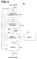
- FIG. 4 depicts provides another exemplary flowchart for illumination normalization 400 using MBAD consistent with yet another embodiment of the present invention.
- MBAD based illumination normalization 400 includes optional geometric normalization 205 , anisotropic diffusion 405 , model 215 , model application 410 , and combine step 220 .
- An input image may first undergo an optional geometric normalization step 205 , which may be the same process described above in illumination normalization 200 shown in FIG. 2 .
- This embodiment differs from illumination normalization 200 in that MBAD 210 is broken down into two components, the first is a conventional anisotropic diffusion process 405 , and the second is a model application process 410 .
- This embodiment differs from the embodiment shown in FIG. 2 in that information from model 215 may not be directly applied during anisotropic diffusion 405 , but may be applied after the input image has undergone anisotropic diffusion, for which the result is referred to as a diffusion image.
- the model information, provided by model 215 is combined with the diffusion image in model application step 410 .
- Model 215 may be the same model discussed above for the embodiment shown in FIG. 2 .
- Anisotropic diffusion 405 may utilize any conventional anisotropic diffusion process known in the art, or for that matter, use any form of known diffusion algorithm.
- Model 215 supplies real edge information to model application 410 .
- This information may be combined with the diffusion image and the input image to improve the filtering process.
- the diffusion image and the input image may be combined using a simple linear combination, wherein values from model 215 provide weights.
- the resultant linear combination produces an illumination estimate L′(x,y).
- M(x,y) may take on values close to zero.
- illumination estimate L′(x,y) will be similar to the input image I(x,y).
- the illumination estimate L′(x,y) may be combined with the input image I(x,y) in combination step 220 .
- the output of geometric normalization step 205 is combined with the illumination estimate L′(x,y).
- the combine step 220 may operate in the same manner as provided above in the description of FIG. 2 .
- the output image of combine step 220 is the reflectance estimate R′(x,y).
- FIG. 5 illustrates an exemplary flowchart for model generation consistent with yet another embodiment of the present invention.
- Model 215 may be created by using a set of training images which each contain a representative object of interest. Each training image may be optionally processed with a geometric normalization process similar to the one described above, to ensure each object is a canonical reference (not shown).
- edge information is extracted from each image in step 510 .
- the edge information may be extracted using any known edge detector, such as, for example, a Sobel edge detector.
- the images may be combined in step 515 .
- the combination may include summing the images together and performing subsequent low pass filtering using a Gaussian kernel.
- the summing and filtering allows illumination and other variations which occur in each individual training image to be averaged out, reducing spurious edges, and reinforcing real edges corresponding to the representative object.
- the filtered image may then have a non-linear function applied, such as, for example, a gamma correction, which is known in the art. Further processing may also convert combined image into a probability lying between 0 and 1.
- the final output is the model 215 which may take the form of a multi-dimensional dataset.
- the training images contained faces as the representative object, and created a model providing information relating to real edges within a face.
- a surface plot 520 of this model is shown in FIG. 5 , where peaks can be seen which correspond to facial features.
- meta information could be added to model 215 to improve accuracy.
- the meta information may include information regarding the sensors which collected the training images, or other information know to one of ordinary skill in the art, such as, for example, the fact that there should be no albedo changes on the nose of a face.
- Other embodiments may allow the model to take the form of a mathematical function instead of a multi-dimensional dataset.
- FIG. 6 shows an exemplary flow diagram for another illumination normalization embodiment 600 consistent with the present invention.
- Direct reflectance estimation (DRE) illumination normalization 600 may include an optional geometric normalization step 205 , MBAD direct reflectance estimation step 710 , and model 215 .
- geometric normalization is optional and used if the input image should be registered to the model 215 .
- Both geometric normalization 205 and model 215 operate as described above in FIGS. 2 and 4 .
- MBAD direct reflectance estimation step can outputs the reflectance estimate R′(x,y) without having to perform the combine step described above in FIGS. 2 and 4 .
- the MBAD parameters are selected so that more filtering is performed in areas which correspond to spurious edges, thus significantly blurring out illumination edges, and leaving real edges corresponding real features on the object in the image, the locations of which are estimated by model 215 .
- the selected parameters within MBAD direct reflectance estimation 710 may be the parameters which control the filtering.
- Another way to increase the amount of filtering would be to alter the filter coefficients so that the filter cutoff point is reduced in frequency, thus narrowing the pass band of the low-pass Gaussian filter.
- FIG. 7 shows an exemplary processing apparatus 700 consistent with another embodiment of the present invention.
- Processing apparatus 700 may include at least one processor 710 , a memory 715 , a mass storage device 720 , an I/O interface 725 , a network interface 727 , an output display 730 , and a user interface 735 .
- processing apparatus 700 can be any data processing equipment known to one of ordinary skill in the art, such as, for example, workstations, personal computers, special purpose computational hardware, special purpose digital image processors, and/or embedded processors.
- Processor 710 can execute instructions and perform calculations on image data based upon program instructions.
- Modules containing executable instructions, and digital image data can be stored wholly or partially in memory 715 , and transferred to processor 710 over a data bus 740 .
- Memory 715 may contain a model generation module 750 to generate model 215 , a geometric normalization module 755 to perform optional geometric normalization 205 , a model based anisotropic diffusion module 760 to perform MBAD 210 which is performed in the model based anisotropic diffusion step 210 shown in FIG. 2 .
- this module could contain a conventional anisotropic diffusion module 765 and a model application module 770 which perform of the anisotropic diffusion step 405 and the model application step 410 provided in the embodiment shown in FIG. 4 .
- Memory 715 also may contain combination module 785 which may perform the combine steps 220 described in FIG. 2 and FIG. 4
- Memory 715 may further contain the model module 775 containing the model 215 , and image data 780 , which could include the input image data, output image data (reflectance estimate R′(x,y)), diffusion image data (illumination estimate L′(x,y)), and the training image data.
- Mass storage 720 can also store program instructions and digital data, and communicate to processor 710 over data bus 740 .
- Processing system can provide and receive other information through I/O interface 725 and network interface 727 , to provide information to users on display 730 , and receive user commands and/or data through user I/O interface 735 .
Abstract
Description
L′(x,y)=I(x,y)[1−M(x,y)]+D(x,y)M(x,y)
-
- where
- L′(x,y): illumination estimate;
- I(x,y): input image
- D(x,y): diffusion image; and
- M(x,y): model values.
- where
Claims (30)
Priority Applications (3)
| Application Number | Priority Date | Filing Date | Title |
|---|---|---|---|
| US11/477,907 US7747045B2 (en) | 2006-06-30 | 2006-06-30 | Method and apparatus for diffusion based illumination normalization |
| JP2008558580A JP5095637B2 (en) | 2006-06-30 | 2007-06-28 | Method and apparatus for diffusion-based illumination normalization |
| PCT/JP2007/063403 WO2008001941A1 (en) | 2006-06-30 | 2007-06-28 | Method and apparatus for diffusion based illumination normalization |
Applications Claiming Priority (1)
| Application Number | Priority Date | Filing Date | Title |
|---|---|---|---|
| US11/477,907 US7747045B2 (en) | 2006-06-30 | 2006-06-30 | Method and apparatus for diffusion based illumination normalization |
Publications (2)
| Publication Number | Publication Date |
|---|---|
| US20080002908A1 US20080002908A1 (en) | 2008-01-03 |
| US7747045B2 true US7747045B2 (en) | 2010-06-29 |
Family
ID=38845694
Family Applications (1)
| Application Number | Title | Priority Date | Filing Date |
|---|---|---|---|
| US11/477,907 Active 2029-01-28 US7747045B2 (en) | 2006-06-30 | 2006-06-30 | Method and apparatus for diffusion based illumination normalization |
Country Status (3)
| Country | Link |
|---|---|
| US (1) | US7747045B2 (en) |
| JP (1) | JP5095637B2 (en) |
| WO (1) | WO2008001941A1 (en) |
Cited By (7)
| Publication number | Priority date | Publication date | Assignee | Title |
|---|---|---|---|---|
| US20090080699A1 (en) * | 2007-09-26 | 2009-03-26 | Honda Motor Co., Ltd. | 3D Beverage Container Localizer |
| US20090290758A1 (en) * | 2008-05-20 | 2009-11-26 | Victor Ng-Thow-Hing | Rectangular Table Detection Using Hybrid RGB and Depth Camera Sensors |
| US20100303372A1 (en) * | 2007-07-26 | 2010-12-02 | Omron Corporation | Digital image processing and enhancing system and method with function of removing noise |
| US20110142298A1 (en) * | 2009-12-14 | 2011-06-16 | Microsoft Corporation | Flexible image comparison and face matching application |
| US20110142299A1 (en) * | 2009-12-14 | 2011-06-16 | Microsoft Corporation | Recognition of faces using prior behavior |
| US20120219215A1 (en) * | 2011-02-24 | 2012-08-30 | Foveon, Inc. | Methods for performing fast detail-preserving image filtering |
| US20140147029A1 (en) * | 2010-06-25 | 2014-05-29 | Kba-Notasys Sa | Method and system for touchless counting of stacked substrates, especially bundled banknotes |
Families Citing this family (13)
| Publication number | Priority date | Publication date | Assignee | Title |
|---|---|---|---|---|
| KR100810326B1 (en) * | 2006-10-10 | 2008-03-04 | 삼성전자주식회사 | Method for generation of multi-resolution 3d model |
| US8588461B2 (en) * | 2010-03-22 | 2013-11-19 | Brigham Young University | Robust watermarking for digital media |
| CN101957912B (en) * | 2010-10-21 | 2012-08-01 | 重庆大学 | Method for obtaining human face illumination invariant images based on multiscale anisotropic diffusion |
| US8675953B1 (en) * | 2011-02-02 | 2014-03-18 | Intuit Inc. | Calculating an object size using images |
| KR102087986B1 (en) * | 2013-10-04 | 2020-03-11 | 삼성전자주식회사 | Method and apparatus for processing image data and medium record of |
| US9342870B2 (en) * | 2013-10-22 | 2016-05-17 | Adobe Systems Incorporated | Tree-based linear regression for denoising |
| CN104463811B (en) * | 2014-12-29 | 2017-08-04 | 南京信息工程大学 | Image smoothing and sharpening method based on energy functional |
| JP6690125B2 (en) * | 2015-03-19 | 2020-04-28 | 富士ゼロックス株式会社 | Image processing device and program |
| US9773154B2 (en) * | 2015-10-09 | 2017-09-26 | Universidad Nacional Autónoma de México | System for the identification and quantification of helminth eggs in environmental samples |
| CN105550646B (en) * | 2015-12-08 | 2020-06-26 | 中山大学 | Generalized illumination invariant face feature description method based on logarithmic gradient histogram |
| CN105894459A (en) * | 2015-12-10 | 2016-08-24 | 乐视云计算有限公司 | Gradient value and direction based image sharpening method and device |
| CN105427262A (en) * | 2015-12-15 | 2016-03-23 | 南京信息工程大学 | Image de-noising method based on bidirectional enhanced diffusion filtering |
| CN105654445B (en) * | 2016-01-28 | 2018-08-21 | 东南大学 | A kind of handset image denoising method based on wavelet transformation edge detection |
Citations (32)
| Publication number | Priority date | Publication date | Assignee | Title |
|---|---|---|---|---|
| US5003618A (en) | 1989-07-14 | 1991-03-26 | University Of Pittsburgh Of The Commonwealth System Of Higher Education | Automatic adaptive anisotropic digital filtering and biasing of digitized images |
| JPH09327024A (en) | 1996-06-07 | 1997-12-16 | Olympus Optical Co Ltd | Image processing unit |
| US5835614A (en) * | 1992-06-26 | 1998-11-10 | Honda Giken Kogyo Kabushiki Kaisha | Image processing apparatus |
| US6122408A (en) * | 1996-04-30 | 2000-09-19 | Siemens Corporate Research, Inc. | Light normalization method for machine vision |
| JP2001008221A (en) | 1999-06-18 | 2001-01-12 | Nippon Telegr & Teleph Corp <Ntt> | Color calibrating method, color calibrating device and storage medium |
| JP2002015311A (en) | 2000-06-30 | 2002-01-18 | Ntt Data Corp | Image recognizing device, shadow removing device, shadow removing method, and storage medium |
| US6498867B1 (en) | 1999-10-08 | 2002-12-24 | Applied Science Fiction Inc. | Method and apparatus for differential illumination image-capturing and defect handling |
| JP2003187223A (en) | 2001-12-19 | 2003-07-04 | Hitachi Ltd | Device, system and method for diagnosing image |
| US6625303B1 (en) * | 1999-02-01 | 2003-09-23 | Eastman Kodak Company | Method for automatically locating an image pattern in digital images using eigenvector analysis |
| US6633655B1 (en) * | 1998-09-05 | 2003-10-14 | Sharp Kabushiki Kaisha | Method of and apparatus for detecting a human face and observer tracking display |
| JP2003331275A (en) | 2002-05-14 | 2003-11-21 | Sharp Corp | Color conversion device |
| US6731821B1 (en) | 2000-09-29 | 2004-05-04 | Hewlett-Packard Development Company, L.P. | Method for enhancing compressibility and visual quality of scanned document images |
| US6803910B2 (en) | 2002-06-17 | 2004-10-12 | Mitsubishi Electric Research Laboratories, Inc. | Rendering compressed surface reflectance fields of 3D objects |
| US6806980B2 (en) * | 2000-12-28 | 2004-10-19 | Xerox Corporation | Adaptive illumination correction of scanned images |
| JP2004336379A (en) | 2003-05-07 | 2004-11-25 | Canon Inc | Image processing method and device |
| US20050078116A1 (en) | 2003-10-10 | 2005-04-14 | Microsoft Corporation | Systems and methods for robust sampling for real-time relighting of objects in natural lighting environments |
| US20050276504A1 (en) | 2004-06-14 | 2005-12-15 | Charles Chui | Image clean-up and pre-coding |
| US20060008171A1 (en) | 2004-07-06 | 2006-01-12 | Microsoft Corporation | Digital photography with flash/no flash extension |
| JP2006014315A (en) | 2005-06-20 | 2006-01-12 | Olympus Corp | System for recording and reproducing color images and method for creating color specification vector data |
| US20060039590A1 (en) * | 2004-08-20 | 2006-02-23 | Silicon Optix Inc. | Edge adaptive image expansion and enhancement system and method |
| US20060072844A1 (en) | 2004-09-22 | 2006-04-06 | Hongcheng Wang | Gradient-based image restoration and enhancement |
| US7031546B2 (en) | 2000-09-12 | 2006-04-18 | Matsushita Electric Industrial Co., Ltd. | Noise reduction method, noise reducing apparatus, medium, medium and program |
| US20060285769A1 (en) * | 2005-06-20 | 2006-12-21 | Samsung Electronics Co., Ltd. | Method, apparatus, and medium for removing shading of image |
| US20070009167A1 (en) * | 2005-07-05 | 2007-01-11 | Dance Christopher R | Contrast enhancement of images |
| US20070047838A1 (en) | 2005-08-30 | 2007-03-01 | Peyman Milanfar | Kernel regression for image processing and reconstruction |
| US7199793B2 (en) | 2002-05-21 | 2007-04-03 | Mok3, Inc. | Image-based modeling and photo editing |
| US20070083114A1 (en) * | 2005-08-26 | 2007-04-12 | The University Of Connecticut | Systems and methods for image resolution enhancement |
| US20070110294A1 (en) | 2005-11-17 | 2007-05-17 | Michiel Schaap | Image enhancement using anisotropic noise filtering |
| US7295716B1 (en) * | 2006-06-30 | 2007-11-13 | Fujifilm Corporation | Method and apparatus for diffusion based image relighting |
| US20080007747A1 (en) * | 2006-06-30 | 2008-01-10 | Fuji Photo Film Co., Ltd. | Method and apparatus for model based anisotropic diffusion |
| US7327882B2 (en) * | 2001-06-26 | 2008-02-05 | Nokia Corporation | Method and device for character location in images from digital camera |
| US7430335B2 (en) | 2003-08-13 | 2008-09-30 | Apple Inc | Pre-processing method and system for data reduction of video sequences and bit rate reduction of compressed video sequences using spatial filtering |
Family Cites Families (4)
| Publication number | Priority date | Publication date | Assignee | Title |
|---|---|---|---|---|
| US20070A (en) * | 1858-04-27 | Samuel e | ||
| JPH03191673A (en) * | 1989-12-21 | 1991-08-21 | Fujitsu Ltd | Black/white edge processing method for color reading device |
| US5819035A (en) * | 1995-10-20 | 1998-10-06 | Matsushita Electric Industrial Co., Ltd. | Post-filter for removing ringing artifacts of DCT coding |
| US7432482B2 (en) * | 2004-07-09 | 2008-10-07 | Sedlmayr Steven R | Distillation and distillate method by microwaves |
-
2006
- 2006-06-30 US US11/477,907 patent/US7747045B2/en active Active
-
2007
- 2007-06-28 JP JP2008558580A patent/JP5095637B2/en active Active
- 2007-06-28 WO PCT/JP2007/063403 patent/WO2008001941A1/en active Application Filing
Patent Citations (34)
| Publication number | Priority date | Publication date | Assignee | Title |
|---|---|---|---|---|
| US5003618A (en) | 1989-07-14 | 1991-03-26 | University Of Pittsburgh Of The Commonwealth System Of Higher Education | Automatic adaptive anisotropic digital filtering and biasing of digitized images |
| US5835614A (en) * | 1992-06-26 | 1998-11-10 | Honda Giken Kogyo Kabushiki Kaisha | Image processing apparatus |
| US6122408A (en) * | 1996-04-30 | 2000-09-19 | Siemens Corporate Research, Inc. | Light normalization method for machine vision |
| JPH09327024A (en) | 1996-06-07 | 1997-12-16 | Olympus Optical Co Ltd | Image processing unit |
| US6633655B1 (en) * | 1998-09-05 | 2003-10-14 | Sharp Kabushiki Kaisha | Method of and apparatus for detecting a human face and observer tracking display |
| US6625303B1 (en) * | 1999-02-01 | 2003-09-23 | Eastman Kodak Company | Method for automatically locating an image pattern in digital images using eigenvector analysis |
| JP2001008221A (en) | 1999-06-18 | 2001-01-12 | Nippon Telegr & Teleph Corp <Ntt> | Color calibrating method, color calibrating device and storage medium |
| US6498867B1 (en) | 1999-10-08 | 2002-12-24 | Applied Science Fiction Inc. | Method and apparatus for differential illumination image-capturing and defect handling |
| JP2002015311A (en) | 2000-06-30 | 2002-01-18 | Ntt Data Corp | Image recognizing device, shadow removing device, shadow removing method, and storage medium |
| US7031546B2 (en) | 2000-09-12 | 2006-04-18 | Matsushita Electric Industrial Co., Ltd. | Noise reduction method, noise reducing apparatus, medium, medium and program |
| US20050041883A1 (en) | 2000-09-29 | 2005-02-24 | Maurer Ron P. | Method for enhancing compressibility and visual quality of scanned document images |
| US6731821B1 (en) | 2000-09-29 | 2004-05-04 | Hewlett-Packard Development Company, L.P. | Method for enhancing compressibility and visual quality of scanned document images |
| US6806980B2 (en) * | 2000-12-28 | 2004-10-19 | Xerox Corporation | Adaptive illumination correction of scanned images |
| US7327882B2 (en) * | 2001-06-26 | 2008-02-05 | Nokia Corporation | Method and device for character location in images from digital camera |
| JP2003187223A (en) | 2001-12-19 | 2003-07-04 | Hitachi Ltd | Device, system and method for diagnosing image |
| JP2003331275A (en) | 2002-05-14 | 2003-11-21 | Sharp Corp | Color conversion device |
| US7199793B2 (en) | 2002-05-21 | 2007-04-03 | Mok3, Inc. | Image-based modeling and photo editing |
| US6803910B2 (en) | 2002-06-17 | 2004-10-12 | Mitsubishi Electric Research Laboratories, Inc. | Rendering compressed surface reflectance fields of 3D objects |
| JP2004336379A (en) | 2003-05-07 | 2004-11-25 | Canon Inc | Image processing method and device |
| US7430335B2 (en) | 2003-08-13 | 2008-09-30 | Apple Inc | Pre-processing method and system for data reduction of video sequences and bit rate reduction of compressed video sequences using spatial filtering |
| US20050078116A1 (en) | 2003-10-10 | 2005-04-14 | Microsoft Corporation | Systems and methods for robust sampling for real-time relighting of objects in natural lighting environments |
| US20050276504A1 (en) | 2004-06-14 | 2005-12-15 | Charles Chui | Image clean-up and pre-coding |
| US20060008171A1 (en) | 2004-07-06 | 2006-01-12 | Microsoft Corporation | Digital photography with flash/no flash extension |
| US20060039590A1 (en) * | 2004-08-20 | 2006-02-23 | Silicon Optix Inc. | Edge adaptive image expansion and enhancement system and method |
| US7529422B2 (en) | 2004-09-22 | 2009-05-05 | Siemens Medical Solutions Usa, Inc. | Gradient-based image restoration and enhancement |
| US20060072844A1 (en) | 2004-09-22 | 2006-04-06 | Hongcheng Wang | Gradient-based image restoration and enhancement |
| US20060285769A1 (en) * | 2005-06-20 | 2006-12-21 | Samsung Electronics Co., Ltd. | Method, apparatus, and medium for removing shading of image |
| JP2006014315A (en) | 2005-06-20 | 2006-01-12 | Olympus Corp | System for recording and reproducing color images and method for creating color specification vector data |
| US20070009167A1 (en) * | 2005-07-05 | 2007-01-11 | Dance Christopher R | Contrast enhancement of images |
| US20070083114A1 (en) * | 2005-08-26 | 2007-04-12 | The University Of Connecticut | Systems and methods for image resolution enhancement |
| US20070047838A1 (en) | 2005-08-30 | 2007-03-01 | Peyman Milanfar | Kernel regression for image processing and reconstruction |
| US20070110294A1 (en) | 2005-11-17 | 2007-05-17 | Michiel Schaap | Image enhancement using anisotropic noise filtering |
| US20080007747A1 (en) * | 2006-06-30 | 2008-01-10 | Fuji Photo Film Co., Ltd. | Method and apparatus for model based anisotropic diffusion |
| US7295716B1 (en) * | 2006-06-30 | 2007-11-13 | Fujifilm Corporation | Method and apparatus for diffusion based image relighting |
Non-Patent Citations (5)
| Title |
|---|
| Du-Ming, Tsai, Shin-Min Chao, "An anisotropic diffusion-based defect detection for sputtered surfaces with inhomogeneous textures", Elsevier: Image and Vision Computing 23 (2005) pp. 325-338. |
| Gross et al., "An image preprocessing algorithm for illumination invariant face recognition", International Conference on Audio-and Video-Based Biometric Person Authentication, pp. 10-18, Jun. 9-11, 2004, Guildford UK. * |
| Hanno Scharr, Michael J. Black and Horst W. Haussecker, "Image Statistics and Anisotropic Diffusion", Proceedings of the Ninth IEEE International Conference on Computer Vision, 2003, pp. 1-8. |
| Lin et al., "A Probablistic DBNN with Applications to Sensor Fusion and Object Recognition", Neural Networks for Signal Processing [1995] V. Proceedings of the 1995 IEEE Workshop, pp. 333-342, Sep. 1995. * |
| Perona, Pietro et al., Scale-Space and Edge Detection Using Anisotropic Diffusion, Jul. 1990, IEEE Transactions on Pattern Analysis and Machine Intelligence, vol. 12, No. 7, pp. 629-639. |
Cited By (15)
| Publication number | Priority date | Publication date | Assignee | Title |
|---|---|---|---|---|
| US20100303372A1 (en) * | 2007-07-26 | 2010-12-02 | Omron Corporation | Digital image processing and enhancing system and method with function of removing noise |
| US8411979B2 (en) * | 2007-07-26 | 2013-04-02 | Omron Corporation | Digital image processing and enhancing system and method with function of removing noise |
| US20090080699A1 (en) * | 2007-09-26 | 2009-03-26 | Honda Motor Co., Ltd. | 3D Beverage Container Localizer |
| US8116519B2 (en) * | 2007-09-26 | 2012-02-14 | Honda Motor Co., Ltd. | 3D beverage container localizer |
| US8265425B2 (en) | 2008-05-20 | 2012-09-11 | Honda Motor Co., Ltd. | Rectangular table detection using hybrid RGB and depth camera sensors |
| US20090290758A1 (en) * | 2008-05-20 | 2009-11-26 | Victor Ng-Thow-Hing | Rectangular Table Detection Using Hybrid RGB and Depth Camera Sensors |
| US8526684B2 (en) * | 2009-12-14 | 2013-09-03 | Microsoft Corporation | Flexible image comparison and face matching application |
| US20110142299A1 (en) * | 2009-12-14 | 2011-06-16 | Microsoft Corporation | Recognition of faces using prior behavior |
| US20110142298A1 (en) * | 2009-12-14 | 2011-06-16 | Microsoft Corporation | Flexible image comparison and face matching application |
| US8644563B2 (en) | 2009-12-14 | 2014-02-04 | Microsoft Corporation | Recognition of faces using prior behavior |
| US20140147029A1 (en) * | 2010-06-25 | 2014-05-29 | Kba-Notasys Sa | Method and system for touchless counting of stacked substrates, especially bundled banknotes |
| US9042632B2 (en) * | 2010-06-25 | 2015-05-26 | Kba-Notasys Sa | Method and system for touchless counting of stacked substrates, especially bundled banknotes |
| US20120219215A1 (en) * | 2011-02-24 | 2012-08-30 | Foveon, Inc. | Methods for performing fast detail-preserving image filtering |
| US8824826B2 (en) * | 2011-02-24 | 2014-09-02 | Foveon, Inc. | Methods for performing fast detail-preserving image filtering |
| US20140363090A1 (en) * | 2011-02-24 | 2014-12-11 | Foveon, Inc. | Methods for Performing Fast Detail-Preserving Image Filtering |
Also Published As
| Publication number | Publication date |
|---|---|
| WO2008001941A1 (en) | 2008-01-03 |
| US20080002908A1 (en) | 2008-01-03 |
| JP5095637B2 (en) | 2012-12-12 |
| JP2009543160A (en) | 2009-12-03 |
Similar Documents
| Publication | Publication Date | Title |
|---|---|---|
| US7747045B2 (en) | Method and apparatus for diffusion based illumination normalization | |
| US7295716B1 (en) | Method and apparatus for diffusion based image relighting | |
| Guo et al. | LIME: Low-light image enhancement via illumination map estimation | |
| Chen et al. | Robust image and video dehazing with visual artifact suppression via gradient residual minimization | |
| US20080007747A1 (en) | Method and apparatus for model based anisotropic diffusion | |
| Gallo et al. | Artifact-free high dynamic range imaging | |
| US20100303372A1 (en) | Digital image processing and enhancing system and method with function of removing noise | |
| Singh et al. | Dehazing of outdoor images using notch based integral guided filter | |
| Yu et al. | Efficient patch-wise non-uniform deblurring for a single image | |
| CN107172354B (en) | Video processing method and device, electronic equipment and storage medium | |
| WO2016139260A9 (en) | Method and system for real-time noise removal and image enhancement of high-dynamic range images | |
| Park et al. | Single image haze removal with WLS-based edge-preserving smoothing filter | |
| KR20140142381A (en) | Method and Apparatus for removing haze in a single image | |
| Shen et al. | Edge-preserving image decomposition using L1 fidelity with L0 gradient | |
| Lenzen et al. | Denoising time-of-flight data with adaptive total variation | |
| Liu et al. | Survey of natural image enhancement techniques: Classification, evaluation, challenges, and perspectives | |
| Kapoor et al. | Fog removal in images using improved dark channel prior and contrast limited adaptive histogram equalization | |
| Li et al. | Image enhancement algorithm based on depth difference and illumination adjustment | |
| CN111199197A (en) | Image extraction method and processing equipment for face recognition | |
| Zhang et al. | Underwater image enhancement via multi-scale fusion and adaptive color-gamma correction in low-light conditions | |
| CN107085839B (en) | SAR image speckle reduction method based on texture enhancement and sparse coding | |
| Rana et al. | Optimizing tone mapping operators for keypoint detection under illumination changes | |
| Han et al. | Automatic illumination and color compensation using mean shift and sigma filter | |
| Kim | Low-light image enhancement by diffusion pyramid with residuals | |
| CN116205802A (en) | Image denoising method and device, storage medium and electronic equipment |
Legal Events
| Date | Code | Title | Description |
|---|---|---|---|
| AS | Assignment |
Owner name: FUJI PHOTO FILM CO., LTD., JAPAN Free format text: ASSIGNMENT OF ASSIGNORS INTEREST;ASSIGNORS:CHINEN, TROY;LEUNG, THOMAS;REEL/FRAME:018027/0439;SIGNING DATES FROM 20060619 TO 20060621 Owner name: FUJI PHOTO FILM CO., LTD.,JAPAN Free format text: ASSIGNMENT OF ASSIGNORS INTEREST;ASSIGNORS:CHINEN, TROY;LEUNG, THOMAS;SIGNING DATES FROM 20060619 TO 20060621;REEL/FRAME:018027/0439 Owner name: FUJI PHOTO FILM CO., LTD., JAPAN Free format text: ASSIGNMENT OF ASSIGNORS INTEREST;ASSIGNORS:CHINEN, TROY;LEUNG, THOMAS;SIGNING DATES FROM 20060619 TO 20060621;REEL/FRAME:018027/0439 |
|
| AS | Assignment |
Owner name: FUJIFILM HOLDINGS CORPORATION, JAPAN Free format text: CHANGE OF NAME;ASSIGNOR:FUJI PHOTO FILM CO., LTD.;REEL/FRAME:018898/0872 Effective date: 20061001 Owner name: FUJIFILM HOLDINGS CORPORATION,JAPAN Free format text: CHANGE OF NAME;ASSIGNOR:FUJI PHOTO FILM CO., LTD.;REEL/FRAME:018898/0872 Effective date: 20061001 |
|
| AS | Assignment |
Owner name: FUJIFILM CORPORATION, JAPAN Free format text: ASSIGNMENT OF ASSIGNORS INTEREST;ASSIGNOR:FUJIFILM HOLDINGS CORPORATION;REEL/FRAME:018934/0001 Effective date: 20070130 Owner name: FUJIFILM CORPORATION,JAPAN Free format text: ASSIGNMENT OF ASSIGNORS INTEREST;ASSIGNOR:FUJIFILM HOLDINGS CORPORATION;REEL/FRAME:018934/0001 Effective date: 20070130 |
|
| FEPP | Fee payment procedure |
Free format text: PAYOR NUMBER ASSIGNED (ORIGINAL EVENT CODE: ASPN); ENTITY STATUS OF PATENT OWNER: LARGE ENTITY |
|
| STCF | Information on status: patent grant |
Free format text: PATENTED CASE |
|
| FPAY | Fee payment |
Year of fee payment: 4 |
|
| MAFP | Maintenance fee payment |
Free format text: PAYMENT OF MAINTENANCE FEE, 8TH YEAR, LARGE ENTITY (ORIGINAL EVENT CODE: M1552) Year of fee payment: 8 |
|
| MAFP | Maintenance fee payment |
Free format text: PAYMENT OF MAINTENANCE FEE, 12TH YEAR, LARGE ENTITY (ORIGINAL EVENT CODE: M1553); ENTITY STATUS OF PATENT OWNER: LARGE ENTITY Year of fee payment: 12 |