US7749170B2 - Multiple configurable electronic thermometer - Google Patents
Multiple configurable electronic thermometer Download PDFInfo
- Publication number
- US7749170B2 US7749170B2 US11/752,155 US75215507A US7749170B2 US 7749170 B2 US7749170 B2 US 7749170B2 US 75215507 A US75215507 A US 75215507A US 7749170 B2 US7749170 B2 US 7749170B2
- Authority
- US
- United States
- Prior art keywords
- thermometer
- controller
- model selection
- selection device
- model
- Prior art date
- Legal status (The legal status is an assumption and is not a legal conclusion. Google has not performed a legal analysis and makes no representation as to the accuracy of the status listed.)
- Active
Links
Images


Classifications
-
- H—ELECTRICITY
- H05—ELECTRIC TECHNIQUES NOT OTHERWISE PROVIDED FOR
- H05K—PRINTED CIRCUITS; CASINGS OR CONSTRUCTIONAL DETAILS OF ELECTRIC APPARATUS; MANUFACTURE OF ASSEMBLAGES OF ELECTRICAL COMPONENTS
- H05K7/00—Constructional details common to different types of electric apparatus
-
- A—HUMAN NECESSITIES
- A61—MEDICAL OR VETERINARY SCIENCE; HYGIENE
- A61B—DIAGNOSIS; SURGERY; IDENTIFICATION
- A61B5/00—Measuring for diagnostic purposes; Identification of persons
- A61B5/01—Measuring temperature of body parts ; Diagnostic temperature sensing, e.g. for malignant or inflamed tissue
-
- G—PHYSICS
- G01—MEASURING; TESTING
- G01K—MEASURING TEMPERATURE; MEASURING QUANTITY OF HEAT; THERMALLY-SENSITIVE ELEMENTS NOT OTHERWISE PROVIDED FOR
- G01K13/00—Thermometers specially adapted for specific purposes
- G01K13/20—Clinical contact thermometers for use with humans or animals
-
- Y—GENERAL TAGGING OF NEW TECHNOLOGICAL DEVELOPMENTS; GENERAL TAGGING OF CROSS-SECTIONAL TECHNOLOGIES SPANNING OVER SEVERAL SECTIONS OF THE IPC; TECHNICAL SUBJECTS COVERED BY FORMER USPC CROSS-REFERENCE ART COLLECTIONS [XRACs] AND DIGESTS
- Y10—TECHNICAL SUBJECTS COVERED BY FORMER USPC
- Y10T—TECHNICAL SUBJECTS COVERED BY FORMER US CLASSIFICATION
- Y10T29/00—Metal working
- Y10T29/49—Method of mechanical manufacture
- Y10T29/49002—Electrical device making
-
- Y—GENERAL TAGGING OF NEW TECHNOLOGICAL DEVELOPMENTS; GENERAL TAGGING OF CROSS-SECTIONAL TECHNOLOGIES SPANNING OVER SEVERAL SECTIONS OF THE IPC; TECHNICAL SUBJECTS COVERED BY FORMER USPC CROSS-REFERENCE ART COLLECTIONS [XRACs] AND DIGESTS
- Y10—TECHNICAL SUBJECTS COVERED BY FORMER USPC
- Y10T—TECHNICAL SUBJECTS COVERED BY FORMER US CLASSIFICATION
- Y10T29/00—Metal working
- Y10T29/49—Method of mechanical manufacture
- Y10T29/49826—Assembling or joining
Definitions
- thermometers often share similar traits, a single model cannot meet the different needs of all, or even most, users.
- a user in an emergency room setting may desire a relatively simple electronic thermometer for quickly and easily obtaining a temperature measurement for a patient.
- the user interface is designed such that the user can turn on the thermometer, take a temperature reading, and then turn it off.
- a user may desire additional functions such as the ability to switch between one predictive mode and another or between a predictive mode and a direct measurement mode, or the ability to switch between different patient body locations (e.g., rectal, oral, or in an axilla) for taking temperature measurements.
- thermometer In addition, users in different countries often have different expectations for performance, functionality, and the like. Thus, a manufacturer must produce several different models of a thermometer, which may have the same basic parts (i.e., a housing, a controller, a probe, and a display), but have different user interfaces, menus, software features, and the like.
- thermometer that is automatically configured, upon initialization, as a particular thermometer model of a plurality of thermometer models.
- Each thermometer even when functioning as a different model, includes the same housing, the same embedded software, and the same controller assembly.
- the universal thermometer comprises a controller having a memory storing a software program.
- the software program contains instructions for implementing all of the user interface menus and features of which the universal thermometer is capable.
- a model selection device e.g., a keypad overlay
- the controller enables and/or disables functions in the software program.
- a manufacturer can produce one type of housing and controller and maintain one software program while having the ability to produce a variety of clinical thermometer models. This may provide, for example, increased manufacturing efficiency and reduced manufacturing and development costs.
- the software program includes profiles for each of a variety of thermometer models.
- a model selection device unique to the particular thermometer model is selected and connected to the controller.
- the controller determines which model selection device is connected and loads the corresponding software profile.
- a model selection device is a user input device or keypad.
- a thin laminate overlay includes a circuit sheet having a series of stainless steel domes mounted thereon. The stainless steel domes function as buttons to form a keypad for the thermometer and are overlaid with a graphic sheet that includes indicia pertaining to the desired thermometer model.
- the overlay may also have an adhesive mounting opposite the graphic sheet for mounting to the thermometer housing.
- the overlay keypad is connected to the main controller circuit board of the thermometer via a ribbon cable or the like and a mating electrical connector on the circuit board.
- the thermometer software scans the overlay keypad circuitry to determine the type of overlay connected. Based upon the type of overlay keypad sensed, the thermometer software will configure itself to function according to the specifications of the particular model by selectively enabling and/or disabling functions of the thermometer.
- FIG. 1 is a perspective of an electronic thermometer according to an embodiment of the invention.
- FIG. 2 is a back view of the thermometer of FIG. 1 having a model selection device installed and a portion of the housing removed.
- FIG. 3 is a partially exploded back view of the thermometer of FIG. 2 .
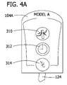
- FIGS. 4A , 4 B, 4 C, and 4 D are front views of alternative model selection devices for use in configuring the thermometer of FIG. 2 as different models according to an embodiment of the invention.
- FIG. 5 schematically illustrates exemplary jumper connections of a plurality of model selection devices for configuring the thermometer of FIG. 2 as different models.
- FIG. 6 is a block diagram illustrating the thermometer of FIG. 2 configured according to the embodiment of FIG. 5 .
- FIG. 7 is an exemplary flow showing aspects of a method of manufacturing a thermometer according to an embodiment of the invention.
- FIG. 1 shows a side elevation view of a clinical thermometer, generally indicated at 100 , according to one embodiment
- FIG. 2 shows a perspective view of the back of the thermometer 100 with a portion of a housing 102 of the thermometer 100 removed.
- the thermometer 100 includes the housing 102 , a user input device such as keypad 104 A, a display 106 , a controller 120 , a power supply (e.g. a battery), and a probe 108 , which is attached to the housing 102 and controller 120 via a probe cord 110 .
- the controller 120 includes a user input device connector 122 for connecting to the keypad 104 A, and a software program having computer executable instructions for displaying the menus of and performing the functions of the thermometer 100 .
- the keypad 104 A also includes a cable 124 for connecting to the user input device connector 122 of the controller 120 .
- the user input device connector 122 shown is a pin header having a plurality of pins for engaging an appropriate pin header connector.
- the cable 124 may be a ribbon cable, a collection of individual wires, or some other conductive means for establishing a connection between the keypad 104 A and the controller 120 .
- the user input device 104 A may directly engage the user input device connector 122 , may be directly installed on the circuit board of the controller 120 , or may communicate with the controller 120 through a wireless means such as Radio Frequency Identification, all of which eliminate cable 124 .
- thermometer 100 constitutes a universal electronic thermometer that is automatically configured, upon initialization, as a particular thermometer model of a plurality of thermometer models.
- the thermometer 100 may include the same housing 102 and the same controller 120 .
- the controller 120 of universal thermometer 100 has a memory (see FIG. 6 ) storing a software program containing instructions for implementing all of the user interface menus and features of which the thermometer is capable.
- a model selection device e.g., a user input device such as keypad 104 A
- corresponding to one particular thermometer model is selected from a plurality of such devices and connected to controller 120 as described above.
- controller 120 enables and/or disables functions in the software program. It is contemplated that the model selection device may also be a sticker for identifying the thermometer model, a model identification nameplate, or the like, each including means for connecting to controller 120 .
- thermometer 100 is shown from the side, partially exploded.
- the cable 124 on keypad 104 A fits through a hole in the housing 102 to engage the connector 122 of the controller 120 .
- the controller 120 is fitted within the rear of housing 102 , and the keypad 104 A is affixed to the front of housing 102 , adjacent to the display 106 as shown in FIG. 1 .
- a user causes the thermometer 100 to initialize by removing probe 108 from its stored position, the user places the probe 108 in contact with a patient at the appropriate temperature measurement location (e.g., oral, rectal, or in an axilla), and the probe 108 passes temperature information to the controller 120 via the probe cord 110 .
- the controller 120 determines the patient's temperature and displays the determined patient temperature to the user via the display 106 . All models of clinical thermometers generally perform this measurement function, but different thermometer models have different default settings, features, and user interface configurations (e.g., menus).
- one model is manufactured with a fast predictive mode for use when temperature measurement speed is more important than accuracy as the default mode of operation and provides a slower, user-selectable standard predictive mode for use when accuracy is more important than speed, such as disclosed in commonly assigned U.S. patent application Ser. No. 11/539,438, filed Oct. 6, 2006, the entire disclosure of which is incorporated herein by reference.
- another model is manufactured with the standard predictive mode as the default mode and the fast predictive mode as a user-selectable option.
- Some models may not allow the thermometer to operate in a measurement mode other than the default mode such that menus related to switching between the fast and standard predictive mode may be eliminated from these models. Some models may also allow a user to manually adjust or calibrate the thermometer, while others do not.
- thermometer models have the same basic parts as described above.
- a thin laminate overlay includes a circuit sheet having a series of stainless steel domes mounted thereon.
- the stainless steel domes function as buttons to form a keypad 104 A for thermometer 100 and are overlaid with a graphic sheet that includes indicia pertaining to the desired thermometer model.
- the overlay may also have an adhesive mounting opposite the graphic sheet for mounting to the thermometer housing.
- the overlay keypad 104 A is connected to the main circuit board of controller 120 via cable 124 and mating electrical connector (e.g., connector 122 ).
- the thermometer software scans the overlay keypad circuitry to determine the type of overlay connected.
- thermometer software Based upon the type of overlay keypad sensed, the thermometer software will configure itself to function according to the specifications of the particular model by selectively enabling and/or disabling functions of the thermometer.
- the software also has instructions for monitoring the sensed keypad periodically during operation of the thermometer for monitoring the thermometer hardware such that if a failure occurs (e.g., keypad 104 A is disconnected from the controller 120 ), the thermometer 100 can display an error on the display 106 .
- the connector 122 may engage the ribbon cable 124 by any connection method such as a pin header and fitting, an array of spade terminals and fittings, a crimp type fitting, an array of solder joints, or epoxy securing bare ribbon cable wires to corresponding circuit board traces.
- keypad 104 A corresponds to a first thermometer model (e.g., Model A) having a first feature set.
- a second user input device 104 B i.e., keypad 104 B of FIG. 4B ) corresponds to a second thermometer model (e.g., Model B) having a second feature set different from the first. It is contemplated that there may be any number of user input devices for use with the thermometer, each user input device corresponding to a different thermometer model having a different feature set, default setting, and/or user interface configuration.
- the keypad 104 A includes three buttons: a measurement site button 310 , a timer button 312 , and a temperature scale button 314 .
- the measurement site button 310 allows the user to select where to take a patient's body temperature (e.g., select oral or axillary).
- the timer button 312 allows the user to take a patient's pulse.
- the t-scale button 314 allows the user to switch the units of the measured temperature shown on the display 106 between Fahrenheit and Celsius.
- the second keypad 104 B includes a temperature site button 320 and a t-scale button 322 .
- the model corresponding to the second keypad 104 B does not provide the timer feature. There may be other differences between the first and second feature sets such as a calibration feature and menu, a default units (i.e., Fahrenheit or Celsius) setting, a default site setting, a default predictive mode setting, etc.
- a full featured model (e.g. Models A and C corresponding to overlays 104 A and 104 C respectively) provides biotech features (e.g., manual thermometer calibration, direct measurement mode (no prediction algorithms used to speed up measurements), anti-theft settings, preheat temperature, programmable device identification number, sound themes, backlight, measurement counter, LCD display test screens, and battery voltage readout but a less featured model (e.g. Models B and D corresponding to overlays 104 B and 104 D respectively) does not provide biotech features.
- biotech features e.g., manual thermometer calibration, direct measurement mode (no prediction algorithms used to speed up measurements), anti-theft settings, preheat temperature, programmable device identification number, sound themes, backlight, measurement counter, LCD display test screens, and battery voltage readout
- a less featured model e.g. Models B and D corresponding to overlays 104 B and 104 D respectively
- the keypad 104 A or 104 B electrically connects at least two pins of the pin header 122 when connected to the pin header 122 . It is contemplated that some user input devices do not electrically connect any of the pins and that other user input devices connect multiple pins or sets of pins.
- the controller 120 determines which pins of the pin header 122 are electrically connected and/or not electrically connected. Based on this determination, the controller 120 sets default parameters of the thermometer 100 and may also selectively enable and/or disable functions and/or menus of the thermometer 100 .
- thermometer 100 is configured as the thermometer model, Model A, corresponding to keypad 104 A when the keypad 104 A is connected, and configured as the thermometer model, Model B, corresponding to the keypad 104 B when the keypad 104 B is connected.
- an exemplary set of connections for the pin header 122 is shown which configure the thermometer 100 as one of a plurality of models (i.e., Models A, B, C, and D). These exemplary connections assume that pin header 122 includes 8 pins.
- the schematics of Models B and D include a connection between pins 8 and 3 and correspond to the 2 button keypads of FIGS. 4B and 4D .
- the schematics for Models A and C do not include a connection between pins 8 and 3 and correspond to the 3 button keypads of FIGS. 4A and 4C .
- the controller 120 can distinguish Models B and D from Models A and C.
- Model B includes a connection between pins 1 and 3 whereas Model D does not, and Model A includes a connection between pins 1 and 3 whereas Model C does not. This allows the controller 120 to further distinguish Model B from Model D, and Model A from Model C.
- the controller 120 can determine the model of a connected keypad and configure the thermometer 100 as the determined model. It is to be understood that other models are available (e.g. by using different pin configurations, decoding schemes, or other component identification schemes).
- thermometer 100 in block diagram form embodying aspects of the invention in accordance with the connections described above with respect to FIG. 5 .
- thermometer 100 constitutes a universal electronic thermometer that is automatically configured, upon initialization, as a particular thermometer model, Model A, B, C, or D.
- the controller 120 of universal thermometer 100 has a memory 602 storing a software program containing instructions for implementing all of the user interface menus and features of which the thermometer is capable.
- controller 120 enables and/or disables features implemented in the software program to cause the thermometer 100 to operate in accordance with the designated model.
- thermometer cores i.e., a thermometer with a model selection device not yet installed
- install model selection devices on demand according to a customer order
- reconfigure thermometers in inventory as a desired thermometer model by replacing the installed model selection devices, or add features to a customer's existing thermometers by replacing the model selection device.
- the controller 120 determines the connected model selection device by retrieving, or receiving, an identification code from the model selection device, wherein all of the model selection devices corresponding to a particular thermometer model provide the same identification code.
- the controller 120 operates the thermometer 100 as a function of the identification code provided by the connected model selection device such that the thermometer 100 is configured as the thermometer model corresponding to the connected model selection device. Transmitting the identification code to the controller 120 may be accomplished via wires, contact, or wirelessly (e.g. via RFID technology).
- the controller 120 stores a plurality of software program profiles, and loads a software profile based on the connected model selection device.
- a touch screen interface is the model selection device and replaces both the user input device and the display and accepts user input and displays the measured patient temperature and menus of the thermometer.
- thermometer 100 a method of manufacturing the thermometer 100 is shown.
- a manufacturer produces a plurality of controllers, housings, displays, and model selection devices.
- the manufacturer assembles the parts (i.e., a controller, a housing, a probe, a cord, a battery, and a display) into a thermometer core (i.e., a thermometer with a model selection device not yet installed).
- a model selection device is selected from a plurality of model selection devices.
- the selected model selection device corresponds to the thermometer model that the manufacturer desires to produce.
- the selected model selection device is connected to the controller of the thermometer core to form a completed thermometer (e.g. thermometer 100 ), and at 410 , the controller operates the thermometer as a function of the connected model selection device.
- Embodiments of the invention may be implemented with computer-executable instructions.
- the computer-executable instructions may be organized into one or more computer-executable components or modules.
- Aspects of the invention may be implemented with any number and organization of such components or modules. For example, aspects of the invention are not limited to the specific computer-executable instructions or the specific components or modules illustrated in the figures and described herein.
- Other embodiments of the invention may include different computer-executable instructions or components having more or less functionality than illustrated and described herein.
Landscapes
- Life Sciences & Earth Sciences (AREA)
- Health & Medical Sciences (AREA)
- Physics & Mathematics (AREA)
- Engineering & Computer Science (AREA)
- Heart & Thoracic Surgery (AREA)
- Public Health (AREA)
- Pathology (AREA)
- Biomedical Technology (AREA)
- Veterinary Medicine (AREA)
- Medical Informatics (AREA)
- Molecular Biology (AREA)
- Surgery (AREA)
- Animal Behavior & Ethology (AREA)
- General Health & Medical Sciences (AREA)
- Biophysics (AREA)
- General Physics & Mathematics (AREA)
- Microelectronics & Electronic Packaging (AREA)
- Measuring And Recording Apparatus For Diagnosis (AREA)
- Measuring Temperature Or Quantity Of Heat (AREA)
Abstract
Description
Claims (7)
Priority Applications (11)
| Application Number | Priority Date | Filing Date | Title |
|---|---|---|---|
| US11/752,155 US7749170B2 (en) | 2007-05-22 | 2007-05-22 | Multiple configurable electronic thermometer |
| IL191564A IL191564A0 (en) | 2007-05-22 | 2008-05-20 | Multiple configuration electronic thermometer |
| CA2631622A CA2631622C (en) | 2007-05-22 | 2008-05-20 | Multiple configuration electronic thermometer |
| AU2008202237A AU2008202237B2 (en) | 2007-05-22 | 2008-05-21 | Multiple configuration electronic thermometer |
| EP08156626A EP1995579B1 (en) | 2007-05-22 | 2008-05-21 | Multiple configuration electronic thermometer |
| TW097118921A TWI372854B (en) | 2007-05-22 | 2008-05-22 | Configurable thermometer and method of manufacturing the same |
| CN200810142875XA CN101310675B (en) | 2007-05-22 | 2008-05-22 | multiple configuration electronic thermometer |
| JP2008134428A JP4870121B2 (en) | 2007-05-22 | 2008-05-22 | Multi-configuration electronic thermometer |
| HK08113349.3A HK1120605A1 (en) | 2007-05-22 | 2008-12-09 | Multiple configuration electronic thermometer |
| US12/796,920 US8449476B2 (en) | 2007-05-22 | 2010-06-09 | Multiple configuration electronic thermometer |
| US13/891,680 US9313910B2 (en) | 2007-05-22 | 2013-05-10 | Multiple configuration electronic thermometer |
Applications Claiming Priority (1)
| Application Number | Priority Date | Filing Date | Title |
|---|---|---|---|
| US11/752,155 US7749170B2 (en) | 2007-05-22 | 2007-05-22 | Multiple configurable electronic thermometer |
Related Child Applications (1)
| Application Number | Title | Priority Date | Filing Date |
|---|---|---|---|
| US12/796,920 Division US8449476B2 (en) | 2007-05-22 | 2010-06-09 | Multiple configuration electronic thermometer |
Publications (2)
| Publication Number | Publication Date |
|---|---|
| US20080294065A1 US20080294065A1 (en) | 2008-11-27 |
| US7749170B2 true US7749170B2 (en) | 2010-07-06 |
Family
ID=39731634
Family Applications (3)
| Application Number | Title | Priority Date | Filing Date |
|---|---|---|---|
| US11/752,155 Active US7749170B2 (en) | 2007-05-22 | 2007-05-22 | Multiple configurable electronic thermometer |
| US12/796,920 Active 2027-12-01 US8449476B2 (en) | 2007-05-22 | 2010-06-09 | Multiple configuration electronic thermometer |
| US13/891,680 Active US9313910B2 (en) | 2007-05-22 | 2013-05-10 | Multiple configuration electronic thermometer |
Family Applications After (2)
| Application Number | Title | Priority Date | Filing Date |
|---|---|---|---|
| US12/796,920 Active 2027-12-01 US8449476B2 (en) | 2007-05-22 | 2010-06-09 | Multiple configuration electronic thermometer |
| US13/891,680 Active US9313910B2 (en) | 2007-05-22 | 2013-05-10 | Multiple configuration electronic thermometer |
Country Status (9)
| Country | Link |
|---|---|
| US (3) | US7749170B2 (en) |
| EP (1) | EP1995579B1 (en) |
| JP (1) | JP4870121B2 (en) |
| CN (1) | CN101310675B (en) |
| AU (1) | AU2008202237B2 (en) |
| CA (1) | CA2631622C (en) |
| HK (1) | HK1120605A1 (en) |
| IL (1) | IL191564A0 (en) |
| TW (1) | TWI372854B (en) |
Cited By (5)
| Publication number | Priority date | Publication date | Assignee | Title |
|---|---|---|---|---|
| US20110022981A1 (en) * | 2009-07-23 | 2011-01-27 | Deepa Mahajan | Presentation of device utilization and outcome from a patient management system |
| US8348894B2 (en) | 2005-07-11 | 2013-01-08 | Covidien Lp | Needle assembly including obturator with safety reset |
| US9299240B2 (en) | 2013-02-27 | 2016-03-29 | Welch Allyn, Inc. | Anti-loss for medical devices |
| USD788605S1 (en) * | 2015-09-01 | 2017-06-06 | Chauvin Arnoux | Measuring apparatus |
| US11366027B2 (en) * | 2015-12-21 | 2022-06-21 | Koninklijke Philips N.V. | Method of predicting a stabilization temperature of a heat-flow sensor |
Families Citing this family (33)
| Publication number | Priority date | Publication date | Assignee | Title |
|---|---|---|---|---|
| US7905857B2 (en) | 2005-07-11 | 2011-03-15 | Covidien Ag | Needle assembly including obturator with safety reset |
| US7850650B2 (en) | 2005-07-11 | 2010-12-14 | Covidien Ag | Needle safety shield with reset |
| US7731692B2 (en) | 2005-07-11 | 2010-06-08 | Covidien Ag | Device for shielding a sharp tip of a cannula and method of using the same |
| US7654735B2 (en) * | 2005-11-03 | 2010-02-02 | Covidien Ag | Electronic thermometer |
| US7749170B2 (en) | 2007-05-22 | 2010-07-06 | Tyco Healthcare Group Lp | Multiple configurable electronic thermometer |
| US8357104B2 (en) | 2007-11-01 | 2013-01-22 | Coviden Lp | Active stylet safety shield |
| US8496377B2 (en) | 2007-12-31 | 2013-07-30 | Covidien Lp | Thermometer having molded probe component |
| JP4388597B1 (en) * | 2008-05-09 | 2009-12-24 | パナソニック株式会社 | Skin incision instrument |
| US8308355B2 (en) * | 2008-07-29 | 2012-11-13 | Welch Allyn, Inc. | Cycle counting |
| US9420952B2 (en) * | 2010-07-27 | 2016-08-23 | Carefusion 303, Inc. | Temperature probe suitable for axillary reading |
| US8814792B2 (en) | 2010-07-27 | 2014-08-26 | Carefusion 303, Inc. | System and method for storing and forwarding data from a vital-signs monitor |
| US9585620B2 (en) | 2010-07-27 | 2017-03-07 | Carefusion 303, Inc. | Vital-signs patch having a flexible attachment to electrodes |
| US9017255B2 (en) | 2010-07-27 | 2015-04-28 | Carefusion 303, Inc. | System and method for saving battery power in a patient monitoring system |
| US9055925B2 (en) | 2010-07-27 | 2015-06-16 | Carefusion 303, Inc. | System and method for reducing false alarms associated with vital-signs monitoring |
| US9615792B2 (en) | 2010-07-27 | 2017-04-11 | Carefusion 303, Inc. | System and method for conserving battery power in a patient monitoring system |
| US9357929B2 (en) | 2010-07-27 | 2016-06-07 | Carefusion 303, Inc. | System and method for monitoring body temperature of a person |
| DE202010011934U1 (en) * | 2010-08-27 | 2011-02-10 | Nawa-Heilmittel Gmbh | Medical hand-held device |
| US8562565B2 (en) | 2010-10-15 | 2013-10-22 | Medtronic Minimed, Inc. | Battery shock absorber for a portable medical device |
| US8603033B2 (en) | 2010-10-15 | 2013-12-10 | Medtronic Minimed, Inc. | Medical device and related assembly having an offset element for a piezoelectric speaker |
| US8603032B2 (en) * | 2010-10-15 | 2013-12-10 | Medtronic Minimed, Inc. | Medical device with membrane keypad sealing element, and related manufacturing method |
| US9459158B2 (en) * | 2010-12-13 | 2016-10-04 | Helen Of Troy Limited | Thermometer with age specific feature selection |
| US8651736B2 (en) | 2012-02-03 | 2014-02-18 | Welch Allyn, Inc. | Probe cover container identification |
| US20130262741A1 (en) * | 2012-03-27 | 2013-10-03 | Robert Marten Bultman | System and method for supporting multiple authentication systems |
| JP5844200B2 (en) * | 2012-03-30 | 2016-01-13 | シチズンホールディングス株式会社 | Contact type internal thermometer |
| USD762850S1 (en) | 2013-04-23 | 2016-08-02 | Covidien Lp | Cassette |
| US9267848B2 (en) * | 2014-01-02 | 2016-02-23 | King Abdullah International Medical Research Center | Thermometer using differential temperature measurements |
| FI20145066L (en) * | 2014-01-23 | 2015-07-24 | Vacon Oyj | Arrangement for providing an electronic device with performance setpoints |
| MX361654B (en) * | 2014-09-22 | 2018-12-13 | Helen Of Troy Ltd | Thermometer with wireless functionality. |
| US9723986B1 (en) | 2016-01-28 | 2017-08-08 | Welch Allyn, Inc. | Physiological parameter measuring system |
| US20220107251A1 (en) | 2019-04-03 | 2022-04-07 | Giatec Scientific Inc. | Embedded sensor devices and methods |
| WO2020211922A1 (en) * | 2019-04-15 | 2020-10-22 | Essity Hygiene And Health Aktiebolag | Data logger unit, sensor unit, absorbent article management system and identification method |
| USD948037S1 (en) * | 2019-11-15 | 2022-04-05 | Kpr U.S., Llc | Cassette |
| CN111000534A (en) * | 2019-12-03 | 2020-04-14 | 南通大学 | Wearable multifunctional human body surface temperature and humidity monitoring equipment and early warning method |
Citations (143)
| Publication number | Priority date | Publication date | Assignee | Title |
|---|---|---|---|---|
| US3702076A (en) | 1970-06-15 | 1972-11-07 | Ivac Corp | Electronic thermometer |
| US3729998A (en) | 1970-08-10 | 1973-05-01 | Royal Medical Corp | Electronic, digital thermometer |
| US3893058A (en) | 1973-03-06 | 1975-07-01 | J & J Manufacturing Corp | Electronic thermometer probe |
| US3915003A (en) | 1972-06-23 | 1975-10-28 | Robert P Adams | Electronic thermometer having a heated probe |
| US4008614A (en) | 1976-04-28 | 1977-02-22 | Johnson & Johnson | Removable probe unit for electronic measuring system |
| US4054057A (en) | 1976-03-01 | 1977-10-18 | Diatek, Inc. | Temperature sensing probe and disposable cover therefor |
| US4112762A (en) | 1976-04-28 | 1978-09-12 | Johnson & Johnson | Probe cover grip and release device |
| US4143348A (en) | 1977-12-05 | 1979-03-06 | The Bendix Corporation | Air temperature sensor connection assembly |
| US4159766A (en) | 1976-11-01 | 1979-07-03 | Diatek, Inc. | Cover for temperature sensing probe |
| US4161880A (en) | 1978-01-05 | 1979-07-24 | Electromedics, Inc. | Linearized digital thermometer |
| US4183248A (en) | 1978-08-08 | 1980-01-15 | Rwb Labs | Fast response electronic thermometer probe |
| US4282507A (en) | 1977-09-13 | 1981-08-04 | Johnson, Matthey & Co., Limited | Measurement of temperature |
| US4307373A (en) | 1977-06-22 | 1981-12-22 | Rosemont Engineering Company Limited | Solid state sensor element |
| US4411535A (en) | 1981-04-01 | 1983-10-25 | Timex Medical Products Corporation | Probe for clinical electronic thermometer |
| US4420738A (en) | 1980-11-26 | 1983-12-13 | Robert Bosch Gmbh | Temperature sensor |
| US4437084A (en) | 1981-10-09 | 1984-03-13 | Cooper Industries, Inc. | Encapsulated, waterproof temperature sensitive device and method of manufacture |
| US4447884A (en) | 1980-12-27 | 1984-05-08 | Sharp Kabushiki Kaisha | Graphic display in an electronic thermometer |
| US4464067A (en) | 1982-01-22 | 1984-08-07 | Citizen Watch Company Limited | Thermistor frequency controlled electronic thermometer |
| US4487208A (en) | 1983-01-21 | 1984-12-11 | Timex Medical Products Corporation | Fast response thermoresistive temperature sensing probe |
| US4531842A (en) | 1983-10-31 | 1985-07-30 | Milton Schonberger | Disposable thermometer probe and rating technique therefor |
| US4536851A (en) | 1982-10-22 | 1985-08-20 | Damon Germanton | Electronic thermometer and associated apparatus |
| US4572365A (en) * | 1985-04-03 | 1986-02-25 | Chesebrough-Pond's Inc. | Probe cover holding and dispensing arrangement for electronic thermometer |
| US4574359A (en) | 1982-12-21 | 1986-03-04 | Terumo Kabushiki Kaisha | Electronic clinical thermometer, and method of measuring body temperature |
| US4592000A (en) | 1982-06-24 | 1986-05-27 | Terumo Corporation | Electronic clinical thermometer, and method of measuring body temperature |
| US4602871A (en) | 1984-10-23 | 1986-07-29 | Citizen Watch Co., Ltd. | Thermistor thermometer |
| FR2580806A1 (en) | 1985-04-19 | 1986-10-24 | Gouault Jean | Thermometric probe for measuring surface temperatures, in particular skin temperatures |
| US4629336A (en) | 1982-06-24 | 1986-12-16 | Terumo Corp. | Electronic clinical thermometer, and method of measuring body temperature |
| US4642785A (en) | 1985-04-10 | 1987-02-10 | Ncr Corporation | Cordless electronic thermometer |
| US4727500A (en) | 1985-05-01 | 1988-02-23 | Sherwood Medical Company | Electronic thermometer with fixed response time |
| US4728199A (en) | 1985-12-31 | 1988-03-01 | Kyushu Hitachi Maxell, Ltd. | Temperature measurement device |
| US4729672A (en) | 1984-11-06 | 1988-03-08 | Terumo Kabushiki Kaisha | Electronic clinical thermometer |
| US4733974A (en) | 1986-07-29 | 1988-03-29 | Qualitrol Corporation | Transformer life consumption indicator |
| US4735512A (en) | 1985-02-05 | 1988-04-05 | Sharp Kabushiki Kaisha | Clinical thermometer |
| US4762429A (en) | 1986-04-22 | 1988-08-09 | Citizen Watch Co., Ltd. | Electronic clinical thermometer with a battery life warning display |
| US4771791A (en) | 1986-02-25 | 1988-09-20 | Benytone Corporation | Apparatus for storing and displaying body temperature |
| US4811198A (en) | 1986-05-13 | 1989-03-07 | Omron Tateisi Electronics Co. | Electronic thermometer having means for predicting a converged temperature |
| US4843577A (en) | 1986-03-04 | 1989-06-27 | Terumo Kabushiki Kaisha | Electronic clinical thermometer |
| US4866621A (en) | 1986-11-05 | 1989-09-12 | Citizen Watch Co., Ltd. | Predictive operation type electronic clinical thermometer |
| US4878184A (en) | 1986-02-10 | 1989-10-31 | Omron Tateisi Electronics Co. | Electronic thermometer with predicting means |
| USD309866S (en) | 1987-09-11 | 1990-08-14 | Terumo Kabushiki Kaisha | Electronic clinical thermometer |
| US4986669A (en) | 1986-11-19 | 1991-01-22 | Terumo Kabushiki Kaisha | Electronic clinical thermometer |
| US5013161A (en) | 1989-07-28 | 1991-05-07 | Becton, Dickinson And Company | Electronic clinical thermometer |
| US5037488A (en) | 1989-07-15 | 1991-08-06 | Heraeus Sensor Gmbh | Temperature sensor construction |
| US5066141A (en) | 1989-10-05 | 1991-11-19 | Terumo Kabushiki Kaisha | Electronic clinical thermometer |
| US5116136A (en) | 1989-06-01 | 1992-05-26 | Massachusetts Institute Of Technology | Temperature measurements using thermistor elements |
| US5133606A (en) | 1989-07-28 | 1992-07-28 | Becton, Dickinson And Company | Electronic clinical thermometer |
| US5142266A (en) | 1987-10-01 | 1992-08-25 | Robert Bosch Gmbh | Ntc temperature sensor and process for producing ntc temperature sensing elements |
| US5149200A (en) | 1988-08-25 | 1992-09-22 | Terumo Kabushiki Kaisha | Temperature measuring probe and electronic clinical thermometer equipped with same |
| US5165798A (en) | 1990-05-25 | 1992-11-24 | Citizen Watch Co., Ltd. | Electronic clinical thermometer with soft flexible casing |
| US5178468A (en) | 1988-08-25 | 1993-01-12 | Terumo Kabushiki Kaisha | Temperature measuring probe and electronic clinical thermometer equipped with same |
| US5207765A (en) | 1990-08-17 | 1993-05-04 | Kurt Eiermann | Sensor for thermal mass flowmeters |
| US5259389A (en) | 1990-10-24 | 1993-11-09 | Terumo Kabushiki Kaisha | Electronic clincal thermometer |
| GB2266771A (en) | 1992-04-22 | 1993-11-10 | Robert Lendrum Fyfe | Heatflow balancing thermometer |
| US5305381A (en) * | 1992-11-09 | 1994-04-19 | Wang Chin Y | Cradle for telephone |
| US5307263A (en) * | 1992-11-17 | 1994-04-26 | Raya Systems, Inc. | Modular microprocessor-based health monitoring system |
| US5370459A (en) | 1993-06-08 | 1994-12-06 | Claud S. Gordon Company | Surface temperature probe with uniform thermocouple junction |
| US5388134A (en) | 1993-02-05 | 1995-02-07 | Dallas Semiconductor Corporation | Integrated circuit thermometer |
| US5392031A (en) | 1992-03-17 | 1995-02-21 | Terumo Kabushiki Kaisha | Electronic clinical thermometer |
| US5438322A (en) | 1994-06-09 | 1995-08-01 | General Railway Signal Corporation | Thermal sensor for detection of potential mechanical failures and transmission of temperature warning signals |
| US5458121A (en) | 1992-09-17 | 1995-10-17 | Terumo Kabushiki Kaisha | Clinical thermometer |
| US5473629A (en) | 1986-08-07 | 1995-12-05 | Terumo Kabushiki Kaisha | Electronic clinical thermometer |
| US5473937A (en) | 1993-05-14 | 1995-12-12 | Texas Instruments Incorporated | Temperature sensing apparatus |
| US5497139A (en) | 1994-09-23 | 1996-03-05 | Matsushita Electric Industrial Co., Ltd. | Temperature sensor and its manufacturing method |
| US5575563A (en) | 1993-07-15 | 1996-11-19 | Chiu; Job | Multiusage thermometer |
| US5632555A (en) | 1994-09-09 | 1997-05-27 | Diatek, L.P. | Medical thermometer |
| US5725308A (en) | 1994-12-23 | 1998-03-10 | Rtd Technology, Inc. | Quick registering thermometer |
| US5738441A (en) | 1995-07-11 | 1998-04-14 | The United States Of America As Represented By The Administrator Of The National Aeronautics And Space Administration | Electronic clinical predictive thermometer using logarithm for temperature prediction |
| US5749656A (en) | 1995-08-11 | 1998-05-12 | General Motors Corporation | Thermal probe assembly with mold-over crimp sensor packaging |
| USD395609S (en) | 1997-05-14 | 1998-06-30 | Welch Allyn, Inc. | Medical thermometer |
| US5789920A (en) | 1995-12-01 | 1998-08-04 | Gebhard Balluff Gmbh & Co. | Position sensor housing having duroplastic molding compound and thermoplastic molding compound |
| US5820263A (en) | 1996-07-15 | 1998-10-13 | Ciobanu; Sorin G. | Apparatus and method for monitoring the temperature of a region of human tissue |
| JPH1130553A (en) | 1997-07-11 | 1999-02-02 | Terumo Corp | Infrared sensor |
| US5883646A (en) | 1993-04-30 | 1999-03-16 | Hewlett-Packard Company | Compact flex-circuit for modular assembly of optical sensor components in an inkjet printer |
| US5887338A (en) | 1996-04-26 | 1999-03-30 | Siemens Aktiengesellschaft | Method for producing a temperature sensor with temperature-dependent resistance |
| US5961451A (en) * | 1997-04-07 | 1999-10-05 | Motorola, Inc. | Noninvasive apparatus having a retaining member to retain a removable biosensor |
| US6006120A (en) * | 1998-10-22 | 1999-12-21 | Palco Labs, Inc. | Cordless Pulse oximeter |
| US6068399A (en) | 1997-11-12 | 2000-05-30 | K-Jump Health Co., Ltd. | Cost-effective electronic thermometer |
| US6091317A (en) | 1998-07-06 | 2000-07-18 | Ford Motor Company | Temperature sensor assembly |
| EP1039281A1 (en) | 1999-03-24 | 2000-09-27 | Techem Aktiengesellschaft & Co. | Measuring insert for resistance thermometer |
| US6147335A (en) | 1997-10-06 | 2000-11-14 | Watlow Electric Manufacturing Co. | Electrical components molded within a polymer composite |
| WO2001031305A1 (en) | 1999-10-24 | 2001-05-03 | Medisim Ltd. | Method for the production of electronic thermometers and a thermometer produced according to the method |
| US6236880B1 (en) * | 1999-05-21 | 2001-05-22 | Raymond R. Raylman | Radiation-sensitive surgical probe with interchangeable tips |
| US6241146B1 (en) | 1997-11-13 | 2001-06-05 | Herarus Electro-Nite International N.V. | Process for manufacturing a sensor arrangement for temperature measurement |
| US6280397B1 (en) | 1997-05-01 | 2001-08-28 | Medism, Ltd. | High speed accurate temperature measuring device |
| US6286995B1 (en) | 1998-09-22 | 2001-09-11 | Denso Corporation | Temperature sensor |
| US6293700B1 (en) | 1999-09-24 | 2001-09-25 | Fluke Corporation | Calibrated isothermal assembly for a thermocouple thermometer |
| US6297723B1 (en) | 1998-01-08 | 2001-10-02 | Matsushita Electric Industrial Co., Ltd. | Temperature sensor and method of manufacturing the same |
| US6337470B1 (en) | 1997-10-06 | 2002-01-08 | Watlow Electric Manufacturing Company | Electrical components molded within a polymer composite |
| US6383144B1 (en) | 2000-01-18 | 2002-05-07 | Edwards Lifesciences Corporation | Devices and methods for measuring temperature of a patient |
| US6418359B1 (en) | 1997-02-28 | 2002-07-09 | Inter Control Hermann Kohler Gmbh & Co. Kg | Control device, especially a temperature control device such as a room temperature control device |
| US20020090020A1 (en) | 2001-01-09 | 2002-07-11 | Mesure Technology Co., Ltd. | Electronic thermometer |
| US20020109577A1 (en) | 2000-12-22 | 2002-08-15 | Heraeus Electro-Nite International N.V. | Electrical resistor with platinum metal or a platinum metal compound and sensor arrangement with the resistor |
| US20020135454A1 (en) | 2001-03-22 | 2002-09-26 | Shunji Ichida | Temperature sensor |
| US6494830B1 (en) * | 2000-06-22 | 2002-12-17 | Guidance Interactive Technologies, Inc. | Handheld controller for monitoring/using medical parameters |
| US20030002562A1 (en) | 2001-06-27 | 2003-01-02 | Yerlikaya Y. Denis | Temperature probe adapter |
| US6511478B1 (en) | 2000-06-30 | 2003-01-28 | Scimed Life Systems, Inc. | Medical probe with reduced number of temperature sensor wires |
| US6534994B1 (en) | 1997-12-20 | 2003-03-18 | Robert Bosch Gmbh | Transducer and method for producing the same |
| US6568849B1 (en) | 2000-04-07 | 2003-05-27 | Cyntec Company | Temperature probe with improved structure integrity and operation reliability over high temperature and voltage |
| US6588931B2 (en) | 2000-12-07 | 2003-07-08 | Delphi Technologies, Inc. | Temperature sensor with flexible circuit substrate |
| US20030128738A1 (en) | 2002-01-08 | 2003-07-10 | Min-Ying Chen | Structure of a clinical thermometer |
| US6591703B2 (en) | 2000-05-05 | 2003-07-15 | Balluff Gmbh | Hermetically encapsulated sensor and process for its production |
| US6607302B2 (en) | 2001-09-24 | 2003-08-19 | Visteon Global Technologies, Inc. | Temperature sensor housing design |
| US20030176810A1 (en) | 2002-03-15 | 2003-09-18 | Maahs Tracy D. | Thermography catheter |
| US6639505B2 (en) | 2001-03-23 | 2003-10-28 | Denso Corporation | Temperature sensor |
| US20030212438A1 (en) | 2002-05-07 | 2003-11-13 | Nova Richard C. | Customization of medical device |
| US6686828B2 (en) | 1999-08-05 | 2004-02-03 | Georg Bernitz | High-temperature detector and method of producing the same |
| US6699188B2 (en) * | 2000-06-22 | 2004-03-02 | Guidance Interactive Technologies | Interactive reward devices and methods |
| US6698922B2 (en) | 2000-11-22 | 2004-03-02 | Denso Corporation | Temperature sensor |
| US20040071182A1 (en) | 2002-10-11 | 2004-04-15 | Welch Allyn, Inc. | Thermometry probe calibration method |
| US20040081225A1 (en) | 2002-10-25 | 2004-04-29 | Janicek Alan J. | Plastic enclosed sensor |
| US6730025B1 (en) * | 1998-11-03 | 2004-05-04 | Harry Louis Platt | Hand held physiological signal acquisition device |
| US20040101029A1 (en) | 2000-08-23 | 2004-05-27 | Morten Brunvoll | Medical thermometer and method for producing medical thermometer |
| US20040105487A1 (en) | 2002-11-28 | 2004-06-03 | Sanlian Chen | Assembly method and structure of an electronic clinical thermometer |
| US6746150B2 (en) | 2000-06-30 | 2004-06-08 | Heraeus Electro-Nite International N.V. | Sensor for detecting the temperature of a fluid |
| US6756585B2 (en) | 2001-03-09 | 2004-06-29 | Heraeus Electro-Nite International N.V. | Process for manufacturing a housing for sensor elements, sensor and use thereof |
| US6782744B1 (en) | 2000-01-24 | 2004-08-31 | Hitachi, Ltd. | Gas flow rate measuring apparatus |
| US6789936B1 (en) * | 1999-06-28 | 2004-09-14 | Braun Gmbh | Infrared thermometer for performing temperature measurements at different sites |
| US6827488B2 (en) | 2002-10-10 | 2004-12-07 | Welch Allyn, Inc. | Sealed probe chamber for thermometry apparatus |
| US6827487B2 (en) | 2001-02-16 | 2004-12-07 | Per Lennart Baumbach | Temperature measuring device |
| US6836651B2 (en) | 1999-06-21 | 2004-12-28 | Telespree Communications | Portable cellular phone system having remote voice recognition |
| US20040264546A1 (en) | 2003-06-24 | 2004-12-30 | Anthony Wong | Infant thermometer |
| US6839651B2 (en) | 2001-06-27 | 2005-01-04 | Sherwood Services Ag | Probe tip thermal isolation and fast prediction algorithm |
| US6854880B2 (en) | 2002-12-04 | 2005-02-15 | Actherm Inc. | Electronic clinical thermometer |
| US6880969B2 (en) | 2001-03-23 | 2005-04-19 | Denso Corporation | Temperature sensor and production method thereof |
| US6899457B2 (en) | 2001-03-14 | 2005-05-31 | Denso Corporation | Thermistor temperature sensor |
| US6918696B2 (en) | 2003-01-15 | 2005-07-19 | Denso Corporation | Temperature sensor and method for manufacturing the same |
| US6938474B2 (en) | 2000-04-04 | 2005-09-06 | Patrik Melvas | Sensing device and method for measuring features in a fluid |
| US20060061451A1 (en) | 2004-09-17 | 2006-03-23 | Shoei-Lai Chen | Personalized control device having security mechanism |
| US7021824B2 (en) | 2003-10-20 | 2006-04-04 | Welch Allyn, Inc. | Switch assembly for thermometry apparatus |
| US7028568B2 (en) | 2002-12-18 | 2006-04-18 | Denso Corporation | Sensor having resin mold casing and method of manufacturing the same |
| US7036984B2 (en) | 2002-11-25 | 2006-05-02 | Lindon Group, Inc. | Digital thermometer for measuring body temperature |
| JP2006186357A (en) | 2003-10-03 | 2006-07-13 | Matsushita Electric Works Ltd | Sensor device and its manufacturing method |
| US7115850B2 (en) | 2003-08-29 | 2006-10-03 | Hella Kgaa Hueck & Co. | Sensor device with three-dimensional switch carrier having differently oriented infrared photodetectors |
| US7183779B2 (en) | 2004-12-28 | 2007-02-27 | Spectrum Technologies, Inc. | Soil probe device and method of making same |
| US7198402B2 (en) | 2003-01-22 | 2007-04-03 | Preh Gmbh | Method for determining an interior temperature of a passenger area of a motor vehicle, arrangement for execution of the method, and a temperature sensor |
| US7218129B2 (en) | 2005-01-12 | 2007-05-15 | International Business Machines Corporation | System, apparatus and method for controlling temperature of an integrated circuit under test |
| US7219544B2 (en) | 2004-09-24 | 2007-05-22 | Denso Corporation | Thermal-type flow rate sensor and manufacturing method thereof |
| US7255475B2 (en) | 2002-10-11 | 2007-08-14 | Welch Allyn, Inc. | Thermometry probe calibration method |
| US20070189358A1 (en) | 2004-11-16 | 2007-08-16 | Welch Allyn, Inc. | Multi-site infrared thermometer |
| US7314310B2 (en) | 2006-04-13 | 2008-01-01 | The General Electric Company | Predictive temperature probe with proximity sensor |
| US7316507B2 (en) | 2005-11-03 | 2008-01-08 | Covidien Ag | Electronic thermometer with flex circuit location |
| US7434991B2 (en) | 2002-12-12 | 2008-10-14 | Covidien Ag | Thermal tympanic thermometer |
| US7613590B2 (en) * | 1992-11-17 | 2009-11-03 | Health Hero Network, Inc. | Modular microprocessor-based power tool system |
Family Cites Families (41)
| Publication number | Priority date | Publication date | Assignee | Title |
|---|---|---|---|---|
| US4317367A (en) * | 1977-03-18 | 1982-03-02 | Milton Schonberger | Fever thermometer, or the like sensor |
| US5700416A (en) * | 1986-02-14 | 1997-12-23 | Sumitomo Chemical Company, Limited | Press molding of thermoplastic resins |
| JPH0249129A (en) | 1987-09-28 | 1990-02-19 | Terumo Corp | Temperature measuring probe and electronic clinical thermometer having probe concerned |
| JPH01312432A (en) | 1988-06-10 | 1989-12-18 | Terumo Corp | Temperature measuring probe and manufacture thereof |
| JP2675344B2 (en) * | 1988-08-25 | 1997-11-12 | テルモ株式会社 | Temperature measuring probe |
| GB9110631D0 (en) * | 1991-05-16 | 1991-07-03 | Kane May Limited | Temperature measuring apparatus |
| US5445154A (en) * | 1993-08-26 | 1995-08-29 | Interspec, Inc. | Ultrasonic probe assembly with linear actuator |
| US5417207A (en) * | 1993-12-06 | 1995-05-23 | Sensor Devices, Inc. | Apparatus for the invasive use of oximeter probes |
| IE940943A1 (en) | 1993-12-09 | 1995-06-14 | Methode Electronics Inc | Printed plastic circuits and contacts and method for making¹same |
| JPH11173922A (en) * | 1997-12-09 | 1999-07-02 | Kyoichi Shimizu | Thermometer |
| FR2778817B1 (en) | 1998-05-18 | 2000-06-30 | Remy Kirchdoerffer | METHOD FOR MANUFACTURING AN APPARATUS OR INSTRUMENT BY MOLDING AND APPARATUS OR INSTRUMENT THUS OBTAINED |
| US6558320B1 (en) * | 2000-01-20 | 2003-05-06 | Medtronic Minimed, Inc. | Handheld personal data assistant (PDA) with a medical device and method of using the same |
| US20050004559A1 (en) * | 2003-06-03 | 2005-01-06 | Senorx, Inc. | Universal medical device control console |
| WO2002093881A2 (en) * | 2001-05-14 | 2002-11-21 | Innovision Research & Technology Plc | Portable communication devices |
| GB0111722D0 (en) * | 2001-05-14 | 2001-07-04 | Innovision Res & Tech Plc | Component identification |
| JP4590128B2 (en) * | 2001-05-18 | 2010-12-01 | 株式会社モリタ製作所 | Functional module type dental medical device, functional module for this medical device, dental medical device and medical functional module unit using this functional module |
| US6634789B2 (en) * | 2001-05-29 | 2003-10-21 | Sherwood Services Ag | Electronic thermometer |
| ATE517574T1 (en) * | 2001-06-29 | 2011-08-15 | Ethicon Inc | SYSTEM FOR ASSESSING URINARY FUNCTION |
| US6969354B1 (en) | 2001-09-25 | 2005-11-29 | Acuson Corporation | Adaptable intraoperative or endocavity ultrasound probe |
| JP2003175005A (en) * | 2001-12-10 | 2003-06-24 | Sony Corp | Health care device and physical condition managing module device to be used therefor |
| US20030149349A1 (en) | 2001-12-18 | 2003-08-07 | Jensen Thomas P. | Integral patch type electronic physiological sensor |
| US7085542B2 (en) * | 2002-05-30 | 2006-08-01 | Motorola, Inc. | Portable device including a replaceable cover |
| WO2005025415A1 (en) * | 2003-09-12 | 2005-03-24 | Fornix Medical Systems Holding B.V. | Apparatus and method for medical measurement |
| NL1021054C1 (en) * | 2002-07-12 | 2004-01-13 | Best Medical Internat Beheer B | Universal measuring device for medical application. |
| US7267547B2 (en) | 2002-08-16 | 2007-09-11 | Kaltenbach & Voigt Gmbh & Co. Kg | Device for regulated heating of media in a dental handpiece |
| US7004622B2 (en) | 2002-11-22 | 2006-02-28 | General Electric Company | Systems and methods for determining conditions of articles and methods of making such systems |
| US7374336B2 (en) | 2003-06-16 | 2008-05-20 | Jacob Fraden | Contact thermometer for body cavity |
| US7303332B2 (en) | 2003-08-29 | 2007-12-04 | Mesure Technology Co., Ltd. | Deflectable probe and thermometer |
| WO2005069974A2 (en) | 2004-01-23 | 2005-08-04 | Children's Hospital Medical Center | Microsensor catheter and method for making the same |
| US20050209813A1 (en) | 2004-03-16 | 2005-09-22 | Johnson Controls Technology Company | Temperature sensing device |
| US8052609B2 (en) | 2005-04-15 | 2011-11-08 | Imacor Inc. | Connectorized probe with serial engagement mechanism |
| WO2006131985A1 (en) * | 2005-06-10 | 2006-12-14 | Mitsubishi Denki Kabushiki Kaisha | Electronic device and cover |
| US7654735B2 (en) * | 2005-11-03 | 2010-02-02 | Covidien Ag | Electronic thermometer |
| US7811239B2 (en) | 2005-12-29 | 2010-10-12 | Intrapartum, Llc | Cervical dilation measurement apparatus |
| US7722247B2 (en) | 2006-10-06 | 2010-05-25 | Covidien Ag | Anti-theft system for thermometer |
| US7549792B2 (en) | 2006-10-06 | 2009-06-23 | Covidien Ag | Electronic thermometer with selectable modes |
| US7507021B2 (en) * | 2006-10-06 | 2009-03-24 | Tyco Healthcare Group Lp | Automatic activating system for thermometer |
| US8593406B2 (en) * | 2007-03-21 | 2013-11-26 | Tegic Communications, Inc. | Interchangeable input modules associated with varying languages |
| US7749170B2 (en) | 2007-05-22 | 2010-07-06 | Tyco Healthcare Group Lp | Multiple configurable electronic thermometer |
| DE102008022615A1 (en) * | 2008-05-06 | 2009-11-19 | K-Jump Health Co., Ltd., Wugu | Replaceable electronic clinical thermometer i.e. mercury clinical thermometer, for determination of e.g. tongue temperature, has circuit identifying sensor part for different applications by removal of pins of connection element |
| TWI355220B (en) | 2008-07-14 | 2011-12-21 | Unimicron Technology Corp | Circuit board structure |
-
2007
- 2007-05-22 US US11/752,155 patent/US7749170B2/en active Active
-
2008
- 2008-05-20 CA CA2631622A patent/CA2631622C/en active Active
- 2008-05-20 IL IL191564A patent/IL191564A0/en unknown
- 2008-05-21 EP EP08156626A patent/EP1995579B1/en active Active
- 2008-05-21 AU AU2008202237A patent/AU2008202237B2/en active Active
- 2008-05-22 CN CN200810142875XA patent/CN101310675B/en active Active
- 2008-05-22 TW TW097118921A patent/TWI372854B/en active
- 2008-05-22 JP JP2008134428A patent/JP4870121B2/en active Active
- 2008-12-09 HK HK08113349.3A patent/HK1120605A1/en not_active IP Right Cessation
-
2010
- 2010-06-09 US US12/796,920 patent/US8449476B2/en active Active
-
2013
- 2013-05-10 US US13/891,680 patent/US9313910B2/en active Active
Patent Citations (149)
| Publication number | Priority date | Publication date | Assignee | Title |
|---|---|---|---|---|
| US3702076A (en) | 1970-06-15 | 1972-11-07 | Ivac Corp | Electronic thermometer |
| US3729998A (en) | 1970-08-10 | 1973-05-01 | Royal Medical Corp | Electronic, digital thermometer |
| US3915003A (en) | 1972-06-23 | 1975-10-28 | Robert P Adams | Electronic thermometer having a heated probe |
| US3893058A (en) | 1973-03-06 | 1975-07-01 | J & J Manufacturing Corp | Electronic thermometer probe |
| US4054057A (en) | 1976-03-01 | 1977-10-18 | Diatek, Inc. | Temperature sensing probe and disposable cover therefor |
| US4008614A (en) | 1976-04-28 | 1977-02-22 | Johnson & Johnson | Removable probe unit for electronic measuring system |
| US4112762A (en) | 1976-04-28 | 1978-09-12 | Johnson & Johnson | Probe cover grip and release device |
| US4159766A (en) | 1976-11-01 | 1979-07-03 | Diatek, Inc. | Cover for temperature sensing probe |
| US4307373A (en) | 1977-06-22 | 1981-12-22 | Rosemont Engineering Company Limited | Solid state sensor element |
| US4282507A (en) | 1977-09-13 | 1981-08-04 | Johnson, Matthey & Co., Limited | Measurement of temperature |
| US4143348A (en) | 1977-12-05 | 1979-03-06 | The Bendix Corporation | Air temperature sensor connection assembly |
| US4161880A (en) | 1978-01-05 | 1979-07-24 | Electromedics, Inc. | Linearized digital thermometer |
| US4183248A (en) | 1978-08-08 | 1980-01-15 | Rwb Labs | Fast response electronic thermometer probe |
| US4420738A (en) | 1980-11-26 | 1983-12-13 | Robert Bosch Gmbh | Temperature sensor |
| US4447884A (en) | 1980-12-27 | 1984-05-08 | Sharp Kabushiki Kaisha | Graphic display in an electronic thermometer |
| US4411535A (en) | 1981-04-01 | 1983-10-25 | Timex Medical Products Corporation | Probe for clinical electronic thermometer |
| US4437084A (en) | 1981-10-09 | 1984-03-13 | Cooper Industries, Inc. | Encapsulated, waterproof temperature sensitive device and method of manufacture |
| US4464067A (en) | 1982-01-22 | 1984-08-07 | Citizen Watch Company Limited | Thermistor frequency controlled electronic thermometer |
| US4629336A (en) | 1982-06-24 | 1986-12-16 | Terumo Corp. | Electronic clinical thermometer, and method of measuring body temperature |
| US4592000A (en) | 1982-06-24 | 1986-05-27 | Terumo Corporation | Electronic clinical thermometer, and method of measuring body temperature |
| US4536851A (en) | 1982-10-22 | 1985-08-20 | Damon Germanton | Electronic thermometer and associated apparatus |
| US4574359A (en) | 1982-12-21 | 1986-03-04 | Terumo Kabushiki Kaisha | Electronic clinical thermometer, and method of measuring body temperature |
| US4487208A (en) | 1983-01-21 | 1984-12-11 | Timex Medical Products Corporation | Fast response thermoresistive temperature sensing probe |
| US4531842A (en) | 1983-10-31 | 1985-07-30 | Milton Schonberger | Disposable thermometer probe and rating technique therefor |
| US4602871A (en) | 1984-10-23 | 1986-07-29 | Citizen Watch Co., Ltd. | Thermistor thermometer |
| US4729672A (en) | 1984-11-06 | 1988-03-08 | Terumo Kabushiki Kaisha | Electronic clinical thermometer |
| US4735512A (en) | 1985-02-05 | 1988-04-05 | Sharp Kabushiki Kaisha | Clinical thermometer |
| US4572365A (en) * | 1985-04-03 | 1986-02-25 | Chesebrough-Pond's Inc. | Probe cover holding and dispensing arrangement for electronic thermometer |
| US4642785A (en) | 1985-04-10 | 1987-02-10 | Ncr Corporation | Cordless electronic thermometer |
| FR2580806A1 (en) | 1985-04-19 | 1986-10-24 | Gouault Jean | Thermometric probe for measuring surface temperatures, in particular skin temperatures |
| US4727500A (en) | 1985-05-01 | 1988-02-23 | Sherwood Medical Company | Electronic thermometer with fixed response time |
| US4728199A (en) | 1985-12-31 | 1988-03-01 | Kyushu Hitachi Maxell, Ltd. | Temperature measurement device |
| US4878184A (en) | 1986-02-10 | 1989-10-31 | Omron Tateisi Electronics Co. | Electronic thermometer with predicting means |
| US4771791A (en) | 1986-02-25 | 1988-09-20 | Benytone Corporation | Apparatus for storing and displaying body temperature |
| US4843577A (en) | 1986-03-04 | 1989-06-27 | Terumo Kabushiki Kaisha | Electronic clinical thermometer |
| US4762429A (en) | 1986-04-22 | 1988-08-09 | Citizen Watch Co., Ltd. | Electronic clinical thermometer with a battery life warning display |
| US4811198A (en) | 1986-05-13 | 1989-03-07 | Omron Tateisi Electronics Co. | Electronic thermometer having means for predicting a converged temperature |
| US4733974A (en) | 1986-07-29 | 1988-03-29 | Qualitrol Corporation | Transformer life consumption indicator |
| US5473629A (en) | 1986-08-07 | 1995-12-05 | Terumo Kabushiki Kaisha | Electronic clinical thermometer |
| US4866621A (en) | 1986-11-05 | 1989-09-12 | Citizen Watch Co., Ltd. | Predictive operation type electronic clinical thermometer |
| US4986669A (en) | 1986-11-19 | 1991-01-22 | Terumo Kabushiki Kaisha | Electronic clinical thermometer |
| US5011294A (en) | 1986-11-19 | 1991-04-30 | Terumo Kabushiki Kaisha | Electronic clinical thermometer |
| USD309866S (en) | 1987-09-11 | 1990-08-14 | Terumo Kabushiki Kaisha | Electronic clinical thermometer |
| US5142266A (en) | 1987-10-01 | 1992-08-25 | Robert Bosch Gmbh | Ntc temperature sensor and process for producing ntc temperature sensing elements |
| US5149200A (en) | 1988-08-25 | 1992-09-22 | Terumo Kabushiki Kaisha | Temperature measuring probe and electronic clinical thermometer equipped with same |
| US5178468A (en) | 1988-08-25 | 1993-01-12 | Terumo Kabushiki Kaisha | Temperature measuring probe and electronic clinical thermometer equipped with same |
| US5116136A (en) | 1989-06-01 | 1992-05-26 | Massachusetts Institute Of Technology | Temperature measurements using thermistor elements |
| US5037488A (en) | 1989-07-15 | 1991-08-06 | Heraeus Sensor Gmbh | Temperature sensor construction |
| US5013161A (en) | 1989-07-28 | 1991-05-07 | Becton, Dickinson And Company | Electronic clinical thermometer |
| US5133606A (en) | 1989-07-28 | 1992-07-28 | Becton, Dickinson And Company | Electronic clinical thermometer |
| US5066141A (en) | 1989-10-05 | 1991-11-19 | Terumo Kabushiki Kaisha | Electronic clinical thermometer |
| US5165798A (en) | 1990-05-25 | 1992-11-24 | Citizen Watch Co., Ltd. | Electronic clinical thermometer with soft flexible casing |
| US5207765A (en) | 1990-08-17 | 1993-05-04 | Kurt Eiermann | Sensor for thermal mass flowmeters |
| US5259389A (en) | 1990-10-24 | 1993-11-09 | Terumo Kabushiki Kaisha | Electronic clincal thermometer |
| US5392031A (en) | 1992-03-17 | 1995-02-21 | Terumo Kabushiki Kaisha | Electronic clinical thermometer |
| GB2266771A (en) | 1992-04-22 | 1993-11-10 | Robert Lendrum Fyfe | Heatflow balancing thermometer |
| US5458121A (en) | 1992-09-17 | 1995-10-17 | Terumo Kabushiki Kaisha | Clinical thermometer |
| US5305381A (en) * | 1992-11-09 | 1994-04-19 | Wang Chin Y | Cradle for telephone |
| US5307263A (en) * | 1992-11-17 | 1994-04-26 | Raya Systems, Inc. | Modular microprocessor-based health monitoring system |
| US7613590B2 (en) * | 1992-11-17 | 2009-11-03 | Health Hero Network, Inc. | Modular microprocessor-based power tool system |
| US5388134A (en) | 1993-02-05 | 1995-02-07 | Dallas Semiconductor Corporation | Integrated circuit thermometer |
| US5513235A (en) | 1993-02-05 | 1996-04-30 | Dallas Semiconductor Corporation | Integrated circuit thermometer |
| US5883646A (en) | 1993-04-30 | 1999-03-16 | Hewlett-Packard Company | Compact flex-circuit for modular assembly of optical sensor components in an inkjet printer |
| US5473937A (en) | 1993-05-14 | 1995-12-12 | Texas Instruments Incorporated | Temperature sensing apparatus |
| US5370459A (en) | 1993-06-08 | 1994-12-06 | Claud S. Gordon Company | Surface temperature probe with uniform thermocouple junction |
| US5575563A (en) | 1993-07-15 | 1996-11-19 | Chiu; Job | Multiusage thermometer |
| US5438322A (en) | 1994-06-09 | 1995-08-01 | General Railway Signal Corporation | Thermal sensor for detection of potential mechanical failures and transmission of temperature warning signals |
| US5632555A (en) | 1994-09-09 | 1997-05-27 | Diatek, L.P. | Medical thermometer |
| US6000846A (en) | 1994-09-09 | 1999-12-14 | Welch Allyn, Inc. | Medical thermometer |
| US5497139A (en) | 1994-09-23 | 1996-03-05 | Matsushita Electric Industrial Co., Ltd. | Temperature sensor and its manufacturing method |
| US5725308A (en) | 1994-12-23 | 1998-03-10 | Rtd Technology, Inc. | Quick registering thermometer |
| US5738441A (en) | 1995-07-11 | 1998-04-14 | The United States Of America As Represented By The Administrator Of The National Aeronautics And Space Administration | Electronic clinical predictive thermometer using logarithm for temperature prediction |
| US5749656A (en) | 1995-08-11 | 1998-05-12 | General Motors Corporation | Thermal probe assembly with mold-over crimp sensor packaging |
| US5789920A (en) | 1995-12-01 | 1998-08-04 | Gebhard Balluff Gmbh & Co. | Position sensor housing having duroplastic molding compound and thermoplastic molding compound |
| US5887338A (en) | 1996-04-26 | 1999-03-30 | Siemens Aktiengesellschaft | Method for producing a temperature sensor with temperature-dependent resistance |
| US5820263A (en) | 1996-07-15 | 1998-10-13 | Ciobanu; Sorin G. | Apparatus and method for monitoring the temperature of a region of human tissue |
| US6418359B1 (en) | 1997-02-28 | 2002-07-09 | Inter Control Hermann Kohler Gmbh & Co. Kg | Control device, especially a temperature control device such as a room temperature control device |
| US5961451A (en) * | 1997-04-07 | 1999-10-05 | Motorola, Inc. | Noninvasive apparatus having a retaining member to retain a removable biosensor |
| US6280397B1 (en) | 1997-05-01 | 2001-08-28 | Medism, Ltd. | High speed accurate temperature measuring device |
| USD395609S (en) | 1997-05-14 | 1998-06-30 | Welch Allyn, Inc. | Medical thermometer |
| JPH1130553A (en) | 1997-07-11 | 1999-02-02 | Terumo Corp | Infrared sensor |
| US6147335A (en) | 1997-10-06 | 2000-11-14 | Watlow Electric Manufacturing Co. | Electrical components molded within a polymer composite |
| US6337470B1 (en) | 1997-10-06 | 2002-01-08 | Watlow Electric Manufacturing Company | Electrical components molded within a polymer composite |
| US6068399A (en) | 1997-11-12 | 2000-05-30 | K-Jump Health Co., Ltd. | Cost-effective electronic thermometer |
| US6241146B1 (en) | 1997-11-13 | 2001-06-05 | Herarus Electro-Nite International N.V. | Process for manufacturing a sensor arrangement for temperature measurement |
| US6534994B1 (en) | 1997-12-20 | 2003-03-18 | Robert Bosch Gmbh | Transducer and method for producing the same |
| US6297723B1 (en) | 1998-01-08 | 2001-10-02 | Matsushita Electric Industrial Co., Ltd. | Temperature sensor and method of manufacturing the same |
| US6091317A (en) | 1998-07-06 | 2000-07-18 | Ford Motor Company | Temperature sensor assembly |
| US6286995B1 (en) | 1998-09-22 | 2001-09-11 | Denso Corporation | Temperature sensor |
| US6006120A (en) * | 1998-10-22 | 1999-12-21 | Palco Labs, Inc. | Cordless Pulse oximeter |
| US6730025B1 (en) * | 1998-11-03 | 2004-05-04 | Harry Louis Platt | Hand held physiological signal acquisition device |
| EP1039281A1 (en) | 1999-03-24 | 2000-09-27 | Techem Aktiengesellschaft & Co. | Measuring insert for resistance thermometer |
| US6236880B1 (en) * | 1999-05-21 | 2001-05-22 | Raymond R. Raylman | Radiation-sensitive surgical probe with interchangeable tips |
| US6836651B2 (en) | 1999-06-21 | 2004-12-28 | Telespree Communications | Portable cellular phone system having remote voice recognition |
| US6789936B1 (en) * | 1999-06-28 | 2004-09-14 | Braun Gmbh | Infrared thermometer for performing temperature measurements at different sites |
| US6686828B2 (en) | 1999-08-05 | 2004-02-03 | Georg Bernitz | High-temperature detector and method of producing the same |
| US6293700B1 (en) | 1999-09-24 | 2001-09-25 | Fluke Corporation | Calibrated isothermal assembly for a thermocouple thermometer |
| WO2001031305A1 (en) | 1999-10-24 | 2001-05-03 | Medisim Ltd. | Method for the production of electronic thermometers and a thermometer produced according to the method |
| US6383144B1 (en) | 2000-01-18 | 2002-05-07 | Edwards Lifesciences Corporation | Devices and methods for measuring temperature of a patient |
| US6782744B1 (en) | 2000-01-24 | 2004-08-31 | Hitachi, Ltd. | Gas flow rate measuring apparatus |
| US6938474B2 (en) | 2000-04-04 | 2005-09-06 | Patrik Melvas | Sensing device and method for measuring features in a fluid |
| US6568849B1 (en) | 2000-04-07 | 2003-05-27 | Cyntec Company | Temperature probe with improved structure integrity and operation reliability over high temperature and voltage |
| US6591703B2 (en) | 2000-05-05 | 2003-07-15 | Balluff Gmbh | Hermetically encapsulated sensor and process for its production |
| US6494830B1 (en) * | 2000-06-22 | 2002-12-17 | Guidance Interactive Technologies, Inc. | Handheld controller for monitoring/using medical parameters |
| US6699188B2 (en) * | 2000-06-22 | 2004-03-02 | Guidance Interactive Technologies | Interactive reward devices and methods |
| US6746150B2 (en) | 2000-06-30 | 2004-06-08 | Heraeus Electro-Nite International N.V. | Sensor for detecting the temperature of a fluid |
| US6979329B2 (en) | 2000-06-30 | 2005-12-27 | Scimed Life Systems, Inc. | Medical probe with reduced number of temperature sensor wires |
| US6511478B1 (en) | 2000-06-30 | 2003-01-28 | Scimed Life Systems, Inc. | Medical probe with reduced number of temperature sensor wires |
| US20040101029A1 (en) | 2000-08-23 | 2004-05-27 | Morten Brunvoll | Medical thermometer and method for producing medical thermometer |
| US6698922B2 (en) | 2000-11-22 | 2004-03-02 | Denso Corporation | Temperature sensor |
| US6588931B2 (en) | 2000-12-07 | 2003-07-08 | Delphi Technologies, Inc. | Temperature sensor with flexible circuit substrate |
| US20020109577A1 (en) | 2000-12-22 | 2002-08-15 | Heraeus Electro-Nite International N.V. | Electrical resistor with platinum metal or a platinum metal compound and sensor arrangement with the resistor |
| US20020090020A1 (en) | 2001-01-09 | 2002-07-11 | Mesure Technology Co., Ltd. | Electronic thermometer |
| US6827487B2 (en) | 2001-02-16 | 2004-12-07 | Per Lennart Baumbach | Temperature measuring device |
| US6756585B2 (en) | 2001-03-09 | 2004-06-29 | Heraeus Electro-Nite International N.V. | Process for manufacturing a housing for sensor elements, sensor and use thereof |
| US6899457B2 (en) | 2001-03-14 | 2005-05-31 | Denso Corporation | Thermistor temperature sensor |
| US20020135454A1 (en) | 2001-03-22 | 2002-09-26 | Shunji Ichida | Temperature sensor |
| US6880969B2 (en) | 2001-03-23 | 2005-04-19 | Denso Corporation | Temperature sensor and production method thereof |
| US6639505B2 (en) | 2001-03-23 | 2003-10-28 | Denso Corporation | Temperature sensor |
| US20030002562A1 (en) | 2001-06-27 | 2003-01-02 | Yerlikaya Y. Denis | Temperature probe adapter |
| US6839651B2 (en) | 2001-06-27 | 2005-01-04 | Sherwood Services Ag | Probe tip thermal isolation and fast prediction algorithm |
| US6607302B2 (en) | 2001-09-24 | 2003-08-19 | Visteon Global Technologies, Inc. | Temperature sensor housing design |
| US20030128738A1 (en) | 2002-01-08 | 2003-07-10 | Min-Ying Chen | Structure of a clinical thermometer |
| US20030176810A1 (en) | 2002-03-15 | 2003-09-18 | Maahs Tracy D. | Thermography catheter |
| US20030212438A1 (en) | 2002-05-07 | 2003-11-13 | Nova Richard C. | Customization of medical device |
| US6827488B2 (en) | 2002-10-10 | 2004-12-07 | Welch Allyn, Inc. | Sealed probe chamber for thermometry apparatus |
| US20040071182A1 (en) | 2002-10-11 | 2004-04-15 | Welch Allyn, Inc. | Thermometry probe calibration method |
| US7255475B2 (en) | 2002-10-11 | 2007-08-14 | Welch Allyn, Inc. | Thermometry probe calibration method |
| US20040081225A1 (en) | 2002-10-25 | 2004-04-29 | Janicek Alan J. | Plastic enclosed sensor |
| US7036984B2 (en) | 2002-11-25 | 2006-05-02 | Lindon Group, Inc. | Digital thermometer for measuring body temperature |
| US6976783B2 (en) | 2002-11-28 | 2005-12-20 | Actherm Inc. | Assembly method and structure of an electronic clinical thermometer |
| US20040105487A1 (en) | 2002-11-28 | 2004-06-03 | Sanlian Chen | Assembly method and structure of an electronic clinical thermometer |
| US6854880B2 (en) | 2002-12-04 | 2005-02-15 | Actherm Inc. | Electronic clinical thermometer |
| US7434991B2 (en) | 2002-12-12 | 2008-10-14 | Covidien Ag | Thermal tympanic thermometer |
| US7028568B2 (en) | 2002-12-18 | 2006-04-18 | Denso Corporation | Sensor having resin mold casing and method of manufacturing the same |
| US6918696B2 (en) | 2003-01-15 | 2005-07-19 | Denso Corporation | Temperature sensor and method for manufacturing the same |
| US7198402B2 (en) | 2003-01-22 | 2007-04-03 | Preh Gmbh | Method for determining an interior temperature of a passenger area of a motor vehicle, arrangement for execution of the method, and a temperature sensor |
| US6957911B2 (en) | 2003-06-24 | 2005-10-25 | Cosco Management, Inc. | Infant thermometer |
| US20040264546A1 (en) | 2003-06-24 | 2004-12-30 | Anthony Wong | Infant thermometer |
| US7115850B2 (en) | 2003-08-29 | 2006-10-03 | Hella Kgaa Hueck & Co. | Sensor device with three-dimensional switch carrier having differently oriented infrared photodetectors |
| JP2006186357A (en) | 2003-10-03 | 2006-07-13 | Matsushita Electric Works Ltd | Sensor device and its manufacturing method |
| US7021824B2 (en) | 2003-10-20 | 2006-04-04 | Welch Allyn, Inc. | Switch assembly for thermometry apparatus |
| US20060061451A1 (en) | 2004-09-17 | 2006-03-23 | Shoei-Lai Chen | Personalized control device having security mechanism |
| US7219544B2 (en) | 2004-09-24 | 2007-05-22 | Denso Corporation | Thermal-type flow rate sensor and manufacturing method thereof |
| US20070189358A1 (en) | 2004-11-16 | 2007-08-16 | Welch Allyn, Inc. | Multi-site infrared thermometer |
| US7183779B2 (en) | 2004-12-28 | 2007-02-27 | Spectrum Technologies, Inc. | Soil probe device and method of making same |
| US7218129B2 (en) | 2005-01-12 | 2007-05-15 | International Business Machines Corporation | System, apparatus and method for controlling temperature of an integrated circuit under test |
| US7316507B2 (en) | 2005-11-03 | 2008-01-08 | Covidien Ag | Electronic thermometer with flex circuit location |
| US7314310B2 (en) | 2006-04-13 | 2008-01-01 | The General Electric Company | Predictive temperature probe with proximity sensor |
Cited By (6)
| Publication number | Priority date | Publication date | Assignee | Title |
|---|---|---|---|---|
| US8348894B2 (en) | 2005-07-11 | 2013-01-08 | Covidien Lp | Needle assembly including obturator with safety reset |
| US20110022981A1 (en) * | 2009-07-23 | 2011-01-27 | Deepa Mahajan | Presentation of device utilization and outcome from a patient management system |
| US9299240B2 (en) | 2013-02-27 | 2016-03-29 | Welch Allyn, Inc. | Anti-loss for medical devices |
| US9761100B2 (en) | 2013-02-27 | 2017-09-12 | Welch Allyn, Inc. | Anti-loss for medical devices |
| USD788605S1 (en) * | 2015-09-01 | 2017-06-06 | Chauvin Arnoux | Measuring apparatus |
| US11366027B2 (en) * | 2015-12-21 | 2022-06-21 | Koninklijke Philips N.V. | Method of predicting a stabilization temperature of a heat-flow sensor |
Also Published As
| Publication number | Publication date |
|---|---|
| CN101310675B (en) | 2012-02-08 |
| US20130242509A1 (en) | 2013-09-19 |
| US9313910B2 (en) | 2016-04-12 |
| AU2008202237B2 (en) | 2011-01-27 |
| TWI372854B (en) | 2012-09-21 |
| CN101310675A (en) | 2008-11-26 |
| US20080294065A1 (en) | 2008-11-27 |
| HK1120605A1 (en) | 2009-04-03 |
| TW200921065A (en) | 2009-05-16 |
| JP4870121B2 (en) | 2012-02-08 |
| CA2631622C (en) | 2012-07-17 |
| US20100250909A1 (en) | 2010-09-30 |
| EP1995579A2 (en) | 2008-11-26 |
| EP1995579B1 (en) | 2013-04-03 |
| AU2008202237A1 (en) | 2008-12-11 |
| US8449476B2 (en) | 2013-05-28 |
| EP1995579A3 (en) | 2011-03-02 |
| JP2009031264A (en) | 2009-02-12 |
| IL191564A0 (en) | 2008-12-29 |
| CA2631622A1 (en) | 2008-11-22 |
Similar Documents
| Publication | Publication Date | Title |
|---|---|---|
| US7749170B2 (en) | Multiple configurable electronic thermometer | |
| KR101589232B1 (en) | Support device for sensors and/or actuators that can be part of a wireless network of sensors/actuators | |
| US8432154B2 (en) | Multimeter having communications via measurement terminals and communication system for same | |
| JP2008545512A (en) | Data collection system and interface | |
| KR20120077753A (en) | Module for measuring blood glucose, smart phone combinable with the module, and method of measuring blood glucose by using the same | |
| US9055900B2 (en) | Specimen measurement device and specimen measurement system | |
| KR20120019940A (en) | Apparatus for analyzing of biosensor | |
| CN108366740B (en) | Portable composite sensor device for measuring multiple biological information and measuring method | |
| US20140236489A1 (en) | Blood glucose measuring kit connectable to mobile device | |
| CN105718338B (en) | Information processing method and electronic equipment | |
| KR100577266B1 (en) | apparatus for evaluating Liquid Crystal DisplayLCD for mobile terminal | |
| CN220584667U (en) | Equipment capable of monitoring printing consumable state | |
| CN219776907U (en) | Temperature measuring assembly | |
| CN204945146U (en) | A kind of Novel glucometer | |
| US20230115904A1 (en) | A modular accessory device for a transmitter device | |
| CN214471487U (en) | Multi-module pressure instrument | |
| TWI630575B (en) | Medical test system and medical test device setting with detachable streaming module thereof | |
| CN116818116A (en) | Temperature measuring assembly, temperature monitoring interaction method, terminal equipment and storage medium | |
| JP7043039B2 (en) | Portable measuring instrument | |
| CN115499316A (en) | Code writer, data transmission method and system | |
| CN102236064A (en) | Limit power on/off test device for electronic product | |
| KR20090113701A (en) | Mobile-phone test device | |
| TWM548517U (en) | Handheld medical measuring system | |
| TWM448259U (en) | Blood sugar meter with detachable voice memory unit |
Legal Events
| Date | Code | Title | Description |
|---|---|---|---|
| AS | Assignment |
Owner name: TYCO HEALTHCARE GROUP LP, MASSACHUSETTS Free format text: ASSIGNMENT OF ASSIGNORS INTEREST;ASSIGNORS:WALDHOFF, GARY J.;BISCH, MICHAEL E.;YERLIKAYA, DENIS Y.;REEL/FRAME:019339/0765;SIGNING DATES FROM 20070510 TO 20070514 Owner name: TYCO HEALTHCARE GROUP LP, MASSACHUSETTS Free format text: ASSIGNMENT OF ASSIGNORS INTEREST;ASSIGNORS:WALDHOFF, GARY J.;BISCH, MICHAEL E.;YERLIKAYA, DENIS Y.;SIGNING DATES FROM 20070510 TO 20070514;REEL/FRAME:019339/0765 |
|
| STCF | Information on status: patent grant |
Free format text: PATENTED CASE |
|
| AS | Assignment |
Owner name: COVIDIEN LP, MASSACHUSETTS Free format text: CHANGE OF NAME;ASSIGNOR:TYCO HEALTHCARE GROUP LP;REEL/FRAME:029595/0101 Effective date: 20120928 |
|
| FPAY | Fee payment |
Year of fee payment: 4 |
|
| AS | Assignment |
Owner name: KPR U.S., LLC, MASSACHUSETTS Free format text: ASSIGNMENT OF ASSIGNORS INTEREST;ASSIGNOR:COVIDIEN LP;REEL/FRAME:044128/0533 Effective date: 20170728 |
|
| MAFP | Maintenance fee payment |
Free format text: PAYMENT OF MAINTENANCE FEE, 8TH YEAR, LARGE ENTITY (ORIGINAL EVENT CODE: M1552) Year of fee payment: 8 |
|
| MAFP | Maintenance fee payment |
Free format text: PAYMENT OF MAINTENANCE FEE, 12TH YEAR, LARGE ENTITY (ORIGINAL EVENT CODE: M1553); ENTITY STATUS OF PATENT OWNER: LARGE ENTITY Year of fee payment: 12 |