US7753465B2 - Method for generating a reference signal for use in an imaging apparatus - Google Patents
Method for generating a reference signal for use in an imaging apparatus Download PDFInfo
- Publication number
- US7753465B2 US7753465B2 US11/549,177 US54917706A US7753465B2 US 7753465 B2 US7753465 B2 US 7753465B2 US 54917706 A US54917706 A US 54917706A US 7753465 B2 US7753465 B2 US 7753465B2
- Authority
- US
- United States
- Prior art keywords
- encoder signal
- encoder
- original
- printhead
- signal
- Prior art date
- Legal status (The legal status is an assumption and is not a legal conclusion. Google has not performed a legal analysis and makes no representation as to the accuracy of the status listed.)
- Expired - Fee Related, expires
Links
- 238000003384 imaging method Methods 0.000 title claims abstract description 37
- 238000000034 method Methods 0.000 title claims abstract description 28
- 230000003750 conditioning effect Effects 0.000 claims abstract description 36
- 230000006870 function Effects 0.000 claims abstract description 34
- 238000012986 modification Methods 0.000 claims abstract description 13
- 230000004048 modification Effects 0.000 claims abstract description 13
- 230000001360 synchronised effect Effects 0.000 claims description 4
- 239000000872 buffer Substances 0.000 description 27
- 230000006854 communication Effects 0.000 description 12
- 238000004891 communication Methods 0.000 description 12
- 238000007639 printing Methods 0.000 description 5
- 238000010586 diagram Methods 0.000 description 4
- 238000001914 filtration Methods 0.000 description 4
- 230000001133 acceleration Effects 0.000 description 3
- 238000012546 transfer Methods 0.000 description 3
- 230000008878 coupling Effects 0.000 description 2
- 238000010168 coupling process Methods 0.000 description 2
- 238000005859 coupling reaction Methods 0.000 description 2
- 239000012530 fluid Substances 0.000 description 2
- 230000032258 transport Effects 0.000 description 2
- 239000008186 active pharmaceutical agent Substances 0.000 description 1
- 230000009286 beneficial effect Effects 0.000 description 1
- 230000007175 bidirectional communication Effects 0.000 description 1
- 230000003139 buffering effect Effects 0.000 description 1
- 238000004364 calculation method Methods 0.000 description 1
- 238000010276 construction Methods 0.000 description 1
- 238000013500 data storage Methods 0.000 description 1
- 238000011161 development Methods 0.000 description 1
- 238000005516 engineering process Methods 0.000 description 1
- 239000004744 fabric Substances 0.000 description 1
- 238000010304 firing Methods 0.000 description 1
- 238000012423 maintenance Methods 0.000 description 1
- 230000008569 process Effects 0.000 description 1
- 238000011160 research Methods 0.000 description 1
Images


Classifications
-
- B—PERFORMING OPERATIONS; TRANSPORTING
- B41—PRINTING; LINING MACHINES; TYPEWRITERS; STAMPS
- B41J—TYPEWRITERS; SELECTIVE PRINTING MECHANISMS, i.e. MECHANISMS PRINTING OTHERWISE THAN FROM A FORME; CORRECTION OF TYPOGRAPHICAL ERRORS
- B41J29/00—Details of, or accessories for, typewriters or selective printing mechanisms not otherwise provided for
- B41J29/38—Drives, motors, controls or automatic cut-off devices for the entire printing mechanism
-
- G—PHYSICS
- G03—PHOTOGRAPHY; CINEMATOGRAPHY; ANALOGOUS TECHNIQUES USING WAVES OTHER THAN OPTICAL WAVES; ELECTROGRAPHY; HOLOGRAPHY
- G03G—ELECTROGRAPHY; ELECTROPHOTOGRAPHY; MAGNETOGRAPHY
- G03G15/00—Apparatus for electrographic processes using a charge pattern
- G03G15/06—Apparatus for electrographic processes using a charge pattern for developing
- G03G15/10—Apparatus for electrographic processes using a charge pattern for developing using a liquid developer
- G03G15/101—Apparatus for electrographic processes using a charge pattern for developing using a liquid developer for wetting the recording material
- G03G15/102—Apparatus for electrographic processes using a charge pattern for developing using a liquid developer for wetting the recording material for differentially wetting the recording material
-
- G—PHYSICS
- G03—PHOTOGRAPHY; CINEMATOGRAPHY; ANALOGOUS TECHNIQUES USING WAVES OTHER THAN OPTICAL WAVES; ELECTROGRAPHY; HOLOGRAPHY
- G03G—ELECTROGRAPHY; ELECTROPHOTOGRAPHY; MAGNETOGRAPHY
- G03G15/00—Apparatus for electrographic processes using a charge pattern
- G03G15/50—Machine control of apparatus for electrographic processes using a charge pattern, e.g. regulating differents parts of the machine, multimode copiers, microprocessor control
Definitions
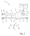
- FIG. 1 is a diagrammatic depiction of an imaging system including an imaging apparatus embodying the present invention
- Algorithm selector 62 may be, for example, a firmware unit formed as part of controller 18 that, based on an algorithm selection signal AS, selects one of a plurality of encoder signal conditioning algorithms, which may be stored, for example, in algorithm selector 62 .
- Each encoder signal conditioning algorithm of the plurality of encoder signal conditioning algorithms is directed to facilitating a specific predefined function of a plurality of desired functions relating to encoder signal ES, and may be used in the generation of a reference signal RS.
- algorithm selector 62 reads values associated with encoder signal ES, e.g., the period(s) of encoder signal ES, into the selected encoder signal conditioning algorithm representing the desired function, to generate at least one parameter which is supplied as firmware write signal FW to reference signal generator 64 .
Abstract
Description
Claims (17)
Priority Applications (1)
| Application Number | Priority Date | Filing Date | Title |
|---|---|---|---|
| US11/549,177 US7753465B2 (en) | 2006-10-13 | 2006-10-13 | Method for generating a reference signal for use in an imaging apparatus |
Applications Claiming Priority (1)
| Application Number | Priority Date | Filing Date | Title |
|---|---|---|---|
| US11/549,177 US7753465B2 (en) | 2006-10-13 | 2006-10-13 | Method for generating a reference signal for use in an imaging apparatus |
Publications (2)
| Publication Number | Publication Date |
|---|---|
| US20080144073A1 US20080144073A1 (en) | 2008-06-19 |
| US7753465B2 true US7753465B2 (en) | 2010-07-13 |
Family
ID=39526778
Family Applications (1)
| Application Number | Title | Priority Date | Filing Date |
|---|---|---|---|
| US11/549,177 Expired - Fee Related US7753465B2 (en) | 2006-10-13 | 2006-10-13 | Method for generating a reference signal for use in an imaging apparatus |
Country Status (1)
| Country | Link |
|---|---|
| US (1) | US7753465B2 (en) |
Cited By (1)
| Publication number | Priority date | Publication date | Assignee | Title |
|---|---|---|---|---|
| US20110090269A1 (en) * | 2009-08-10 | 2011-04-21 | Ricoh Company, Limited | Image forming apparatus |
Families Citing this family (3)
| Publication number | Priority date | Publication date | Assignee | Title |
|---|---|---|---|---|
| US8388104B2 (en) * | 2007-07-25 | 2013-03-05 | Hewlett-Packard Development Company, L.P. | Determining encoder strip expansion |
| US8559794B2 (en) * | 2010-05-21 | 2013-10-15 | International Business Machines Corporation | System and method for recording collaborative information |
| WO2018230138A1 (en) * | 2017-06-15 | 2018-12-20 | パナソニック インテレクチュアル プロパティ コーポレーション オブ アメリカ | Terminal and communication method |
Citations (8)
| Publication number | Priority date | Publication date | Assignee | Title |
|---|---|---|---|---|
| US4415286A (en) * | 1981-09-17 | 1983-11-15 | Printronix, Inc. | Variable print density encoder system |
| US4789874A (en) * | 1987-07-23 | 1988-12-06 | Hewlett-Packard Company | Single channel encoder system |
| US5288157A (en) * | 1990-05-15 | 1994-02-22 | Seiko Epson Corporation | Printing control system having means to correct flight time |
| US6471319B1 (en) * | 2001-07-09 | 2002-10-29 | Lexmark International, Inc. | Method for synchronizing print start positions for an inkjet printer carriage |
| US6609781B2 (en) | 2000-12-13 | 2003-08-26 | Lexmark International, Inc. | Printer system with encoder filtering arrangement and method for high frequency error reduction |
| US20050128235A1 (en) * | 2003-12-12 | 2005-06-16 | Hao-Feng Hung | Inkjet printer correction device and method |
| US7036902B2 (en) * | 2002-08-22 | 2006-05-02 | Canon Kabushiki Kaisha | Printing apparatus |
| US7168781B2 (en) * | 2004-08-19 | 2007-01-30 | Aetas System Incorporated | Method of encoder signal compensation and apparatus thereof |
-
2006
- 2006-10-13 US US11/549,177 patent/US7753465B2/en not_active Expired - Fee Related
Patent Citations (8)
| Publication number | Priority date | Publication date | Assignee | Title |
|---|---|---|---|---|
| US4415286A (en) * | 1981-09-17 | 1983-11-15 | Printronix, Inc. | Variable print density encoder system |
| US4789874A (en) * | 1987-07-23 | 1988-12-06 | Hewlett-Packard Company | Single channel encoder system |
| US5288157A (en) * | 1990-05-15 | 1994-02-22 | Seiko Epson Corporation | Printing control system having means to correct flight time |
| US6609781B2 (en) | 2000-12-13 | 2003-08-26 | Lexmark International, Inc. | Printer system with encoder filtering arrangement and method for high frequency error reduction |
| US6471319B1 (en) * | 2001-07-09 | 2002-10-29 | Lexmark International, Inc. | Method for synchronizing print start positions for an inkjet printer carriage |
| US7036902B2 (en) * | 2002-08-22 | 2006-05-02 | Canon Kabushiki Kaisha | Printing apparatus |
| US20050128235A1 (en) * | 2003-12-12 | 2005-06-16 | Hao-Feng Hung | Inkjet printer correction device and method |
| US7168781B2 (en) * | 2004-08-19 | 2007-01-30 | Aetas System Incorporated | Method of encoder signal compensation and apparatus thereof |
Cited By (2)
| Publication number | Priority date | Publication date | Assignee | Title |
|---|---|---|---|---|
| US20110090269A1 (en) * | 2009-08-10 | 2011-04-21 | Ricoh Company, Limited | Image forming apparatus |
| US8333455B2 (en) * | 2009-08-10 | 2012-12-18 | Ricoh Company, Ltd. | Image forming apparatus |
Also Published As
| Publication number | Publication date |
|---|---|
| US20080144073A1 (en) | 2008-06-19 |
Similar Documents
| Publication | Publication Date | Title |
|---|---|---|
| US7914112B2 (en) | Printing apparatus with switchover section that switches over patterns of velocity data | |
| JP2009040007A (en) | Image recorder | |
| US7753465B2 (en) | Method for generating a reference signal for use in an imaging apparatus | |
| JP2017154443A (en) | Inkjet recording device | |
| CN107116899B (en) | Image forming apparatus, image forming method, and computer readable medium | |
| US8845055B2 (en) | Control apparatus for a liquid ejecting head, liquid ejecting apparatus, and control method for a liquid ejecting head | |
| JP2012061758A (en) | Image forming system, program, and storage medium storing the program | |
| JP2011148287A (en) | Image forming apparatus | |
| JP2015193085A (en) | Recording system, inkjet recording device and program | |
| JP2007160532A (en) | Liquid ejector | |
| JP3888347B2 (en) | Liquid ejecting apparatus and driving method thereof | |
| US10081177B2 (en) | Ink-jet recording apparatus | |
| JP2005169808A (en) | Liquid injection device and its drive method | |
| JP2013163292A (en) | Inkjet recording device | |
| JP2011201213A (en) | Printer, control method for the same, and program | |
| US7918527B2 (en) | Method for use in achieving velocity optimization for a printhead | |
| JP2023145153A (en) | Liquid discharge device and program | |
| US7320511B2 (en) | Image forming apparatus and high-resolution printing method in a horizontal direction | |
| JP2007307744A (en) | Image forming apparatus | |
| JP2020049878A (en) | Image formation apparatus, image formation method and program | |
| JP2005349604A (en) | Inkjet recorder and inkjet recording method | |
| JP2023170172A (en) | Recording device, control method of the same and program | |
| JP4411978B2 (en) | Image recording device | |
| JP6127680B2 (en) | Image forming apparatus, image forming system, and image forming method | |
| US20070146756A1 (en) | Method of operating an imaging apparatus having a duplexer and a perforation device |
Legal Events
| Date | Code | Title | Description |
|---|---|---|---|
| AS | Assignment |
Owner name: LEXMARK INTERNATIONAL, INC., KENTUCKY Free format text: ASSIGNMENT OF ASSIGNORS INTEREST;ASSIGNORS:GRIESEMER, FREDERICK CHARLES;HENRY, DARREL LEE;MARRA, MICHAEL ANTHONY, III;AND OTHERS;REEL/FRAME:018390/0839;SIGNING DATES FROM 20061009 TO 20061011 Owner name: LEXMARK INTERNATIONAL, INC., KENTUCKY Free format text: ASSIGNMENT OF ASSIGNORS INTEREST;ASSIGNORS:GRIESEMER, FREDERICK CHARLES;HENRY, DARREL LEE;MARRA, MICHAEL ANTHONY, III;AND OTHERS;SIGNING DATES FROM 20061009 TO 20061011;REEL/FRAME:018390/0839 |
|
| STCF | Information on status: patent grant |
Free format text: PATENTED CASE |
|
| FPAY | Fee payment |
Year of fee payment: 4 |
|
| MAFP | Maintenance fee payment |
Free format text: PAYMENT OF MAINTENANCE FEE, 8TH YEAR, LARGE ENTITY (ORIGINAL EVENT CODE: M1552) Year of fee payment: 8 |
|
| AS | Assignment |
Owner name: CHINA CITIC BANK CORPORATION LIMITED, GUANGZHOU BR Free format text: PATENT SECURITY AGREEMENT;ASSIGNOR:LEXMARK INTERNATIONAL, INC.;REEL/FRAME:046989/0396 Effective date: 20180402 |
|
| AS | Assignment |
Owner name: CHINA CITIC BANK CORPORATION LIMITED, GUANGZHOU BR Free format text: CORRECTIVE ASSIGNMENT TO CORRECT THE INCORRECT U.S. PATENT NUMBER PREVIOUSLY RECORDED AT REEL: 046989 FRAME: 0396. ASSIGNOR(S) HEREBY CONFIRMS THE PATENT SECURITY AGREEMENT;ASSIGNOR:LEXMARK INTERNATIONAL, INC.;REEL/FRAME:047760/0795 Effective date: 20180402 |
|
| FEPP | Fee payment procedure |
Free format text: MAINTENANCE FEE REMINDER MAILED (ORIGINAL EVENT CODE: REM.); ENTITY STATUS OF PATENT OWNER: LARGE ENTITY |
|
| LAPS | Lapse for failure to pay maintenance fees |
Free format text: PATENT EXPIRED FOR FAILURE TO PAY MAINTENANCE FEES (ORIGINAL EVENT CODE: EXP.); ENTITY STATUS OF PATENT OWNER: LARGE ENTITY |
|
| STCH | Information on status: patent discontinuation |
Free format text: PATENT EXPIRED DUE TO NONPAYMENT OF MAINTENANCE FEES UNDER 37 CFR 1.362 |
|
| FP | Lapsed due to failure to pay maintenance fee |
Effective date: 20220713 |
|
| AS | Assignment |
Owner name: LEXMARK INTERNATIONAL, INC., KENTUCKY Free format text: RELEASE BY SECURED PARTY;ASSIGNOR:CHINA CITIC BANK CORPORATION LIMITED, GUANGZHOU BRANCH, AS COLLATERAL AGENT;REEL/FRAME:066345/0026 Effective date: 20220713 |