US7753932B2 - Medical device and related methods of packaging - Google Patents
Medical device and related methods of packaging Download PDFInfo
- Publication number
- US7753932B2 US7753932B2 US10/808,427 US80842704A US7753932B2 US 7753932 B2 US7753932 B2 US 7753932B2 US 80842704 A US80842704 A US 80842704A US 7753932 B2 US7753932 B2 US 7753932B2
- Authority
- US
- United States
- Prior art keywords
- medical device
- grooves
- groove
- handle
- end effector
- Prior art date
- Legal status (The legal status is an assumption and is not a legal conclusion. Google has not performed a legal analysis and makes no representation as to the accuracy of the status listed.)
- Expired - Fee Related, expires
Links
Images


Classifications
-
- A—HUMAN NECESSITIES
- A61—MEDICAL OR VETERINARY SCIENCE; HYGIENE
- A61B—DIAGNOSIS; SURGERY; IDENTIFICATION
- A61B10/00—Other methods or instruments for diagnosis, e.g. instruments for taking a cell sample, for biopsy, for vaccination diagnosis; Sex determination; Ovulation-period determination; Throat striking implements
- A61B10/02—Instruments for taking cell samples or for biopsy
- A61B10/06—Biopsy forceps, e.g. with cup-shaped jaws
-
- A—HUMAN NECESSITIES
- A61—MEDICAL OR VETERINARY SCIENCE; HYGIENE
- A61B—DIAGNOSIS; SURGERY; IDENTIFICATION
- A61B90/00—Instruments, implements or accessories specially adapted for surgery or diagnosis and not covered by any of the groups A61B1/00 - A61B50/00, e.g. for luxation treatment or for protecting wound edges
- A61B90/50—Supports for surgical instruments, e.g. articulated arms
Definitions
- Embodiments of the invention relate to a medical device having a proximal portion that can selectively receive other portions of the device. More specifically, embodiments of the invention relate to an endoscopic instrument with a handle portion configured to accommodate an elongate, flexible member and an end effector assembly of the endoscopic instrument for protection, coiling, looping, containment, packaging and for disposal.
- the device may have a variety of configurations.
- a biopsy forceps device samples tissue from a body cavity with minimal intervention and discomfort to patients.
- a biopsy forceps device like other endoscopic instruments, has a long flexible tubular member (a catheter) for insertion into a lumen of an endoscope.
- the tubular member is sufficiently long and flexible to follow a long, winding path of the body cavity.
- the elongate member may be 240 cm long or longer.
- An end effector assembly such as a biopsy forceps assembly, is attached at a distal end of the tubular member, and a handle is attached at a proximal end of the tubular member.
- the handle may have an elongate portion and spool portion disposed around the elongate portion configured to move longitudinally relative to the elongate portion.
- An elongate mechanism such as pull wires, extends through the tubular member to connect the end effector assembly and a portion of the handle, such as the spool.
- the pull wires may also be connected to the portion of the handle, such as the spool, via a hypotube. Longitudinal movement of the spool relative to the elongate portion of the handle causes the elongate mechanism to move longitudinally in the tubular member, which in turn causes the actuation of the end effector assembly.
- the long flexible tubular member and end effector assembly are packaged, contained, protected, and/or disposed of in a variety of ways.
- the long flexible tubular member can be looped or coiled so that it is more compact, and then tied by wrapping the distal most portion (a few inches thereof) around the coils or loops.
- a cap may be placed on the end effector assembly both to protect the end effector assembly and prevent it from getting caught on an external object or surface.
- an embodiment of the invention includes a medical device including a handle, an end effector assembly, and an elongate, flexible member connecting the handle to the end effector assembly.
- the handle defines at least one groove configured to accommodate at least one of a portion of the elongate member and a portion of the end effector assembly.
- Another embodiment of the invention includes a medical device including a handle, an end effector assembly, and an elongate, flexible member connecting the handle to the end effector assembly. At least one of a portion of the elongate member and a portion of the end effector assembly is disposed in at least one groove defined by the handle.
- a further embodiment of the invention includes a method of packaging a medical device including providing a medical device including a handle, an end effector assembly, and an elongate, flexible member connecting the handle to the end effector assembly.
- the handle defines at least one groove configured to accommodate at least one of a portion of the elongate member and a portion of the end effector assembly.
- the method further includes forming at least one loop of the elongate member, and placing at least one of the at least one loop of the elongate member and the portion of the end effector assembly in the at least one groove.
- Various embodiments of the present invention may include a handle including an elongate portion and a spool portion disposed around the elongate portion.
- the spool portion may include a proximal portion and a distal portion connected by a central portion.
- the handle may include a channel and/or notch configured to accommodate the end effector.
- the handle may include a throughhole.
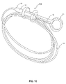
- FIG. 1 is a plan view of an exemplary endoscopic instrument suitable for use in connection with embodiments according to the present invention.
- FIGS. 2-7 are perspective views of a portions of proximal handles of an endoscopic instrument according to different embodiments of the present invention.
- FIG. 7A is a schematic view of the proximal handle portion of FIG. 7 , showing a spool portion accommodating an end effector assembly.
- FIG. 8A is a perspective view of a portion of a proximal handle according to a yet further embodiment of the present invention.
- FIG. 8B is a cross-sectional view of the handle portion of FIG. 8A .
- FIG. 8C is a perspective view of an elongate portion for use with the handle portion of FIG. 8A .
- FIG. 9 is a perspective view of a portion of a proximal handle of an endoscopic instrument of FIG. 2 , accommodating portions of an elongate member, according to an embodiment of the present invention.
- FIG. 10 is a perspective view of an endoscopic instrument of FIG. 6 , accommodating portions of an elongate member, according to another embodiment of the present invention.
- FIG. 11A is a perspective view of a portion of a proximal handle of an endoscopic instrument according to another embodiment of the present invention.
- FIG. 11B is a cross-sectional view of the handle portion of FIG. 11A .
- Various embodiments of the invention relate to an endoscopic instrument having a proximal portion that can selectively receive other portions of the device, including the elongate member and end effector assembly.
- Embodiments of the invention also relate to related methods of packaging and/or storing an endoscopic instrument.
- the elongate member may be coiled or looped, for example to minimize the volume of the packaged device, and stored with the assistance of the proximal receiving portion.
- the end effector assembly also may be packaged and/or stored with the assistance of the proximal receiving portion, for example, to preserve the integrity of the end effector assembly and/or to protect the user during handling of the medical device.
- the proximal receiving portion may be a portion of the medical device itself, such as a portion of the proximal handle.
- the receiving portion may be a separate part coupled to the medical device and used for packaging and/or storing the medical device and not otherwise used in the medical procedure.
- FIG. 1 An exemplary endoscopic instrument 1 which may be used in connection with a proximal receiving portion according to an embodiment of the invention is depicted in FIG. 1 .
- the endoscopic instrument 1 has a handle 10 , an elongate member 14 , and an end effector assembly 15 .
- the handle 10 includes a spool-like device 20 and a ring portion 11 attached to and/or integrally formed with an elongate portion 12 .
- the device 20 is substantially coaxial with and disposed around the elongate portion 12 , and is configured to move longitudinally with respect to the elongate portion 12 .
- the handle 10 and more specifically the elongate portion 12 , is connected to a proximal end of the member 14 via an elongate member interface 13 .
- the member 14 is connected to the assembly 15 , an example of which is shown in FIG. 1 as being a biopsy forceps device.
- the biopsy forceps device is only exemplary, however, and any other end effector assembly known in the art may be used as the assembly 15 .
- Longitudinal movement of the device 20 relative to the elongate member 12 causes the actuation of the assembly 15 .
- the device 20 causes actuation of the assembly 15 through control wires 24 , 25 that are connected to the device 20 and the assembly 15 , and extend through hollow portions of the elongate member 12 and member 14 .
- the control wires 24 , 25 are connected to the device 20 via a hypotube 26 .
- the spool-like device 20 has proximal portion 21 , a distal portion 22 , and a central portion 23 .
- a user may insert a thumb into ring portion 11 and two fingers about central portion 23 to grip and actuate handle 10 .
- the proximal portion 21 is larger in diameter than the distal portion 22
- both the proximal portion 21 and distal portion 22 have a larger diameter than the central portion 23 .
- any of the portions of the device 20 in FIG. 1 or in the various embodiments disclosed in this application, may have differing dimensions and sizes relative to each other.
- proximal handle 10 receives portions of the medical device that selectively accommodate other portions of the medical device (such as member 14 and assembly 15 )
- the embodiments include the spool-like device including configurations that receive member 14 and/or assembly 15 .
- Other portions of proximal handle 10 such as ring portion 11 and/or elongate portion 12 may be configured to have similar features as the spool-like device embodiments.
- the device 800 has a proximal portion 810 , a distal portion 820 , and a central portion 830 .
- the proximal portion 810 has a groove 811 configured to accommodate at least one of a portion of the member 14 and at least a portion of the assembly 15 .
- the distal portion 820 has a groove 821 configured to accommodate at least one of a portion of the member 14 and at least a portion of the assembly 15 .
- the grooves 811 , 821 may also be configured to accommodate more than one portion of the member 14 , for example, multiple loops of the member 14 and/or at least a portion of the assembly 15 .
- a throughhole 823 within device 800 (through portions 810 , 820 , and 830 ) is configured to accommodate the elongate portion 12 of the handle 10 .
- At least one of the grooves 811 , 821 may be composed of at least one material configured to allow the at least one groove to more effectively grip and/or retain at least a portion of the end effector assembly 15 .
- the at least one material may comprise all or any portion of the spool 800 , proximal portion 810 , distal portion 820 , and/or portions of the spool 800 that define the at least one groove 811 , 821 .
- FIG. 2 A further embodiment of the spool-like device is depicted in FIG. 2 .
- the device 100 has a proximal portion 110 , a distal portion 120 , and a central portion 130 .
- the proximal portion 110 has a radial groove 111 and a circumferential groove 112 off the radial groove 111 configured to accommodate multiple loops of the member 14 .
- a throughhole 123 within device 100 (through portions 110 , 120 , and 130 ) is configured to accommodate the elongate portion 12 of the handle 10 .
- Various loops of the member 14 are placed through the radial groove 111 and then may be moved into the circumferential groove 112 .
- Both the radial groove 111 and the circumferential groove 112 have a width greater than the diameter of the member 14 , and have a combined length greater than the aggregate diameters of the desired number of loops of member 14 that will be placed there (e.g., at least three loops of the member 14 ).
- the circumferential groove 112 itself may have a sufficient length to accommodate all of the desired number of loops of member 14 .
- the distal portion 120 has a notch 121 configured to accommodate one loop of the member 14 .
- the notch 121 has a width that is substantially the same as the diameter of the member 14 , and a length sufficient to retain member 14 , such as at least one-half the diameter of the member 14 .
- the notch 121 may be configured so that the member 14 does not fall out of the notch 121 despite minor jostling, for example, by having a width slightly narrower than the diameter of the member 14 so that the member 14 is press-fit into the notch 121 .
- FIG. 9 depicts an exemplary embodiment of loops of member 14 stored on the handle, for example, by being placed in grooves on the device.
- FIG. 9 shows loops of member 14 stored in the device 100 of FIG. 2 .
- the device 200 has a proximal portion 210 , a distal portion 220 , and a central portion 230 .
- the proximal portion 210 has a groove 211 configured to accommodate multiple loops of the member 14 , and a notch 212 configured to accommodate one loop of the member 14 .
- a throughhole 213 within device 200 (through portions 210 , 220 , and 230 ) is configured to accommodate the elongate portion 12 of the handle 10 .
- the groove 211 has a width greater than a diameter of the member 14 and a length greater than the aggregate diameters of the desired number of member 14 loops to be placed in the groove 211 .
- the notch 212 has a width approximately the same as the diameter of the member 14 , and a length sufficient to retain member 14 , such as at least one-half the diameter of the member 14 .
- the notch 212 may be configured so that the member 14 can be press-fit into the notch 212 , for example, by having a width slightly narrower than the diameter of the member 14 .
- the distal portion 220 has a groove 221 substantially similar and corresponding to groove 211 on the proximal portion 210 , and a notch 222 substantially similar and corresponding to groove 212 on the proximal portion 210 .
- the desired number of loops of member 14 are placed in grooves 211 , 221 , and then the last loop is placed in notches 212 , 222 .
- the portion of the last loop in the notches 212 , 222 is near the distal end of the member 14 connected to the assembly 15 .
- the central portion 230 may have a groove 231 that connects the bottom portions of grooves 211 and 221 .
- the groove 231 may accommodate at least a portion of a member 14 (e.g., less than one width).
- the device 300 has a proximal portion 310 , a distal portion 320 , and a central portion 330 .
- the proximal portion 310 has a plurality of grooves 311 each configured to accommodate at least one loop of the member 14 .
- a throughhole 313 within device 300 is configured to accommodate the elongate portion 12 of the handle 10 .
- Each groove 311 has a width dimension approximately the same as (i.e., slightly larger or slightly smaller than) the diameter of the member 14 and a length sufficient to retain member 14 , such as at least one-half the width of the diameter of the member 14 .
- Each groove 311 or a subset of the grooves 311 may be configured to allow the member 14 to be press-fit into the grooves 311 .
- the distal portion 320 has a plurality of grooves 321 substantially similar and corresponding to grooves 311 on the proximal portion 310 .
- One corresponding pair of grooves 311 , 321 on the proximal portion 310 and distal portion 320 respectively, accommodates the last loop of the member 14 which is near the distal end of the member 14 connected to the assembly 15 .
- the loops of member 14 may be placed in the grooves 311 , 321 in succession, for example the most proximal loop is placed in the first grooves 311 , 321 and then each successive loop is placed in the next adjacent grooves 311 , 321 going clockwise, so as to minimize tangling, and may be removed in the opposite order so as to minimize the same.
- any of the loops of the member 14 may be placed in any of the grooves in any order.
- the device 400 has a proximal portion 410 , a distal portion 420 , and a central portion 430 .
- the proximal portion 410 has a plurality of grooves 411 configured to accommodate at least one loop of the member 14 .
- a throughhole 413 within device 400 is configured to accommodate the elongate portion 12 of the handle 10 .
- Each groove 411 has a width approximately the same as (i.e., slightly larger or slightly smaller) the diameter of the member 14 and a length sufficient to retain member 14 , such as at least one-half the width of the diameter of the member 14 .
- Each groove 411 or a subset of the grooves 411 may be configured to allow the member 14 to be press-fit into the grooves 411 .
- the distal portion 420 has a plurality of grooves 421 substantially similar and corresponding to grooves 411 on the proximal portion 410 .
- the distal portion 420 also has one notch 422 , that corresponds to one of the grooves 411 of the proximal portion 410 and is configured to accommodate assembly 15 connected to the distal end of the member 14 .
- the proximal loop of the member 14 is placed in the grooves 411 , 421 furthest from the notch 422 , and then each successive loop of the member 14 is placed in successive grooves 411 , 421 going toward the notch 422 , until the last loop of the member 14 is placed in groove 411 corresponding to the notch 422 , and the assembly 15 is placed in the notch 422 .
- the notch 422 is configured to hold at least a portion of the assembly 15 until removed by the user so as to both protect the assembly 15 from damage from outside elements, as well as to prevent the assembly 15 from interacting with the outside environment, including injury to the user.
- the notch 422 would prevent the biopsy forceps from snagging or catching on anything else in the operating room environment, including the user or the patient. In such a case, the notch 422 could be shaped similarly to any portion of the assembly 15 .
- the device 500 has a proximal portion 510 , a distal portion 520 , and a central portion 530 .
- the proximal portion 510 has a groove 511 configured to accommodate multiple loops of the member 14 , and a notch 512 configured to accommodate at least one loop of the member 14 .
- a throughhole 513 within device 500 (through portions 510 , 520 , and 530 ) is configured to accommodate the elongate portion 12 of the handle 10 .
- the groove 511 is substantially similar to the groove 211 in FIG. 3
- the notch 512 is substantially similar to the notch 212 in FIG. 3 .
- the distal portion 520 has a groove 521 configured to accommodate multiple loops of the member 14 , and a channel 522 configured to accommodate at least a portion of an assembly 15 .
- Channel 522 may have, for example, an internal surface that has a size and/or shape similar to an external surface of assembly 15 .
- the groove 521 is substantially similar to the groove 221 in FIG. 3 .
- the central portion 530 has a groove 531 substantially similar to the groove 231 in FIG. 3
- the channel 522 on the distal portion 520 corresponds substantially to the circumferential location of the notch 512 on the proximal portion 510 , and is set radially inward from the outer edge of the distal portion 520 .
- Channel 522 extends partially through portion 520 or may extend through the entire width of the distal portion 520 .
- the desired number of loops of the member 14 are placed in the grooves 511 , 521 , 531 .
- the last loop of the member is placed in the notch 512 , and then the assembly 15 is placed in the channel 522 for substantially the same reasons for placing the assembly 15 in the notch 422 of FIG. 5 .
- the channel 522 may be adapted to be used with any assembly 15 , and is also configured to prevent or at least discourage the assembly 15 from exiting the channel 522 without user interaction, for example, by slightly press fitting the assembly 15 into the channel 522 .
- FIG. 10 depicts an exemplary embodiment of loops of member 14 stored on the handle, for example, by being placed in grooves on the device.
- FIG. 10 shows loops of member 14 stored in the device 500 of FIG. 6 .
- FIG. 7 A further embodiment of a spool-like device is depicted in FIG. 7 .
- the device 600 has a proximal portion 610 , a distal portion 620 , and a central portion 630 .
- the proximal portion 610 has a groove 611 configured to accommodate multiple loops of the member 14 and a groove 612 configured to accommodate the assembly 15 and a portion of the member 14 .
- a throughhole 613 within device 600 (through portions 610 , 620 , and 630 ) is configured to accommodate the elongate portion 12 of the handle 10 .
- the groove 611 is substantially similar to the groove 211 in FIG. 3 .
- the distal portion 620 has a groove 621 configured to accommodate multiple loops of the member 14 .
- the groove 621 is substantially similar to the groove 221 in FIG. 3 .
- the central portion 630 has a groove 631 configured to accommodate multiple loops of the member 14 .
- the groove 631 is substantially similar to the groove 231 in FIG. 3 .
- the groove 612 extends through substantially the entire width of the proximal portion 610 and may extend into a groove 632 on the central portion 630 .
- the assembly 15 on the distal end of the member 14 is placed into the groove 612 and advanced until either the assembly 15 is snuggly fitted into the groove 612 , or the assembly 15 reaches the end of the groove 612 , as shown in FIG. 7A .
- the assembly 15 may then continue to extend into groove 632 on the central portion 630 .
- a portion of member 14 may or may not be in the groove 612 as well.
- a portion of the assembly 15 may emerge through the surface of the central portion 630 , for example, so that the user can ascertain that the assembly 15 has been securely placed in the groove 612 .
- the assembly 15 is placed in channel 612 for the same reasons the assembly 15 is placed in the notch 422 of FIG. 5 .
- FIGS. 8A-8C Yet another embodiment of a spool-like device is depicted in FIGS. 8A-8C .
- the device 700 has a proximal portion 710 , a distal portion 720 , and a central portion 730 .
- the proximal portion 710 has a radial groove 711 , a grooved throughhole 712 , and a narrower groove 713 .
- the narrower groove 713 connects the radial groove 711 to the grooved throughhole 712 .
- the radial groove 711 has a width sufficient to receive a member 14 and an assembly 15 .
- the narrower groove 713 extends through central portion 730 via narrower groove 731 and terminates at groove 721 in the distal portion 720 .
- the radial groove 711 continues through at least a portion of the central portion 730 via wider groove 732 .
- Wider groove 732 also has a width sufficient to receive a member 14 and an assembly 15 , and tapers at its distal end so that it is configured, for example, to receive the end of the assembly 15 .
- the depth of the wider groove 732 is sufficient to retain member 14 , for example, at least about one-half the diameter of the member 14 , so as to allow the member 14 and assembly 15 to be press-fit into the wider groove 732 .
- loops of the member 14 may be placed in the radial groove 711 .
- the last portion of the member 14 which is connected to the assembly 15 , may then be placed in the grooves 711 , 732 with the assembly 15 being placed at the distal end of the wider groove 732 , and the member 14 extending out proximally from the groove 711 .
- the grooved throughhole 712 is configured to receive an elongate portion of the handle 10 , for example, as shown in FIG. 8C .
- the elongate portion 740 has a thumb ring 741 defining a thumb hole 742 therein, and an elongate T-shaped portion 743 with a groove 745 extending until it becomes a tapered T-shaped portion 744 .
- the tapered T-shaped portion 744 is configured to be placed in the grooved throughhole 712 such that the ridge 714 is placed in the groove 745 , and the vertical portion 746 is at least partially placed in the narrower groove 713 .
- the T-shaped portion 744 may serve several purposes, for example, it may be used to align the elongate portion 740 in the device 700 and/or it may impart strength to the elongate portion 740 (i.e., make the elongate portion 740 more resistant to strains and/or torsional stresses). In various embodiments, however, the T-shaped portion need not be T-shaped, and may instead have any desired cross-sectional geometry.
- the location of the grooves and/or notches on the device relative to each other may changed as desirable.
- the grooves and/or notches may be on opposite sides of the proximal and/or distal portions.
- the grooves and/or notches may be sized to accommodate a member 14 having any number of diameters and/or any number of lengths.
- the grooves and/or notches may be configured (i.e., have widths and lengths and numbers) to accommodate any number of loops of the member 14 having any diameter.
- any of the features depicted in the embodiments shown in FIGS. 1-8C may be removed and/or they may be mixed and/or combined with any other features in those other embodiments.
- any of the proximal portions may be substituted for any of the distal portions and vice versa.
- proximal and distal are exemplary only, and are not meant to limit any of the embodiments to any particular orientation and/or configuration.
- all the loops of the member 14 may be placed inside one sufficiently sized groove on the device.
- the grooves and/or notches may be composed of at least one material configured to allow the grooves and/or notches to more effectively grip and/or retain at least a portion of the end effector assembly 15 .
- the at least one material may comprise all or any portion of the spool, proximal portion, distal portion, grooves, and/or notches.
- the tendency of the catheter to become twisted and tangled, as it is prone to do in the conventional arrangement, is reduced, making the instrument less cumbersome and time consuming to unpack and prepare for use.
- embodiments of the invention allow the user to recoil the member 14 of the device after use, allowing for safer disposal of the device.
- the various features of the invention set forth above may be used in any medical or non-medical procedure with any medical or non-medical device.
- the principles of the invention may be used in connection with other types of medical device handles, such as scissors-like handles or any other suitable handles.
- the elongate endoscopic instrument can be advanced down the working channel of an endoscope, through the working channel cap that has a seal specifically designed for use with the elongate endoscopic instrument, and into a tissue tract.
- the end effector assembly of the elongate endoscopic instrument can be actuated, for example, taking and storing one or multiple biopsy samples using a biopsy forceps device, and then be extracted from the tissue tract through the working channel of the endoscope.
Abstract
Description
Claims (56)
Priority Applications (1)
| Application Number | Priority Date | Filing Date | Title |
|---|---|---|---|
| US10/808,427 US7753932B2 (en) | 2004-03-25 | 2004-03-25 | Medical device and related methods of packaging |
Applications Claiming Priority (1)
| Application Number | Priority Date | Filing Date | Title |
|---|---|---|---|
| US10/808,427 US7753932B2 (en) | 2004-03-25 | 2004-03-25 | Medical device and related methods of packaging |
Publications (2)
| Publication Number | Publication Date |
|---|---|
| US20050216029A1 US20050216029A1 (en) | 2005-09-29 |
| US7753932B2 true US7753932B2 (en) | 2010-07-13 |
Family
ID=34991071
Family Applications (1)
| Application Number | Title | Priority Date | Filing Date |
|---|---|---|---|
| US10/808,427 Expired - Fee Related US7753932B2 (en) | 2004-03-25 | 2004-03-25 | Medical device and related methods of packaging |
Country Status (1)
| Country | Link |
|---|---|
| US (1) | US7753932B2 (en) |
Cited By (36)
| Publication number | Priority date | Publication date | Assignee | Title |
|---|---|---|---|---|
| US10507108B2 (en) | 2017-04-18 | 2019-12-17 | Edwards Lifesciences Corporation | Heart valve sealing devices and delivery devices therefor |
| US10507109B2 (en) | 2018-01-09 | 2019-12-17 | Edwards Lifesciences Corporation | Native valve repair devices and procedures |
| US10507102B2 (en) | 2009-12-04 | 2019-12-17 | Edwards Lifesciences Corporation | Prosthetic valve for replacing mitral valve |
| US10517726B2 (en) | 2015-05-14 | 2019-12-31 | Edwards Lifesciences Corporation | Heart valve sealing devices and delivery devices therefor |
| US10524792B2 (en) | 2014-12-04 | 2020-01-07 | Edwards Lifesciences Corporation | Percutaneous clip for repairing a heart valve |
| US10595997B2 (en) | 2018-01-09 | 2020-03-24 | Edwards Lifesciences Corporation | Native valve repair devices and procedures |
| US10646342B1 (en) | 2017-05-10 | 2020-05-12 | Edwards Lifesciences Corporation | Mitral valve spacer device |
| US10653862B2 (en) | 2016-11-07 | 2020-05-19 | Edwards Lifesciences Corporation | Apparatus for the introduction and manipulation of multiple telescoping catheters |
| US10667912B2 (en) | 2017-04-18 | 2020-06-02 | Edwards Lifesciences Corporation | Heart valve sealing devices and delivery devices therefor |
| US10799675B2 (en) | 2016-03-21 | 2020-10-13 | Edwards Lifesciences Corporation | Cam controlled multi-direction steerable handles |
| US10799676B2 (en) | 2016-03-21 | 2020-10-13 | Edwards Lifesciences Corporation | Multi-direction steerable handles for steering catheters |
| US10799677B2 (en) | 2016-03-21 | 2020-10-13 | Edwards Lifesciences Corporation | Multi-direction steerable handles for steering catheters |
| US10799312B2 (en) | 2017-04-28 | 2020-10-13 | Edwards Lifesciences Corporation | Medical device stabilizing apparatus and method of use |
| US10806575B2 (en) | 2008-08-22 | 2020-10-20 | Edwards Lifesciences Corporation | Heart valve treatment system |
| US10813760B2 (en) | 2018-01-09 | 2020-10-27 | Edwards Lifesciences Corporation | Native valve repair devices and procedures |
| US10835714B2 (en) | 2016-03-21 | 2020-11-17 | Edwards Lifesciences Corporation | Multi-direction steerable handles for steering catheters |
| US10905554B2 (en) | 2017-01-05 | 2021-02-02 | Edwards Lifesciences Corporation | Heart valve coaptation device |
| US10918483B2 (en) | 2018-01-09 | 2021-02-16 | Edwards Lifesciences Corporation | Native valve repair devices and procedures |
| US10925735B2 (en) | 2018-01-09 | 2021-02-23 | Edwards Lifesciences Corporation | Native valve repair devices and procedures |
| US10945844B2 (en) | 2018-10-10 | 2021-03-16 | Edwards Lifesciences Corporation | Heart valve sealing devices and delivery devices therefor |
| US10959847B2 (en) | 2018-01-09 | 2021-03-30 | Edwards Lifesciences Corporation | Native valve repair devices and procedures |
| US10973639B2 (en) | 2018-01-09 | 2021-04-13 | Edwards Lifesciences Corporation | Native valve repair devices and procedures |
| US10973638B2 (en) | 2016-07-07 | 2021-04-13 | Edwards Lifesciences Corporation | Device and method for treating vascular insufficiency |
| US11013598B2 (en) | 2018-01-09 | 2021-05-25 | Edwards Lifesciences Corporation | Native valve repair devices and procedures |
| US11039925B2 (en) | 2018-01-09 | 2021-06-22 | Edwards Lifesciences Corporation | Native valve repair devices and procedures |
| US11040174B2 (en) | 2017-09-19 | 2021-06-22 | Edwards Lifesciences Corporation | Multi-direction steerable handles for steering catheters |
| US11051940B2 (en) | 2017-09-07 | 2021-07-06 | Edwards Lifesciences Corporation | Prosthetic spacer device for heart valve |
| US11065117B2 (en) | 2017-09-08 | 2021-07-20 | Edwards Lifesciences Corporation | Axisymmetric adjustable device for treating mitral regurgitation |
| US11207181B2 (en) | 2018-04-18 | 2021-12-28 | Edwards Lifesciences Corporation | Heart valve sealing devices and delivery devices therefor |
| US11219746B2 (en) | 2016-03-21 | 2022-01-11 | Edwards Lifesciences Corporation | Multi-direction steerable handles for steering catheters |
| US11259927B2 (en) | 2018-01-09 | 2022-03-01 | Edwards Lifesciences Corporation | Native valve repair devices and procedures |
| US11298228B2 (en) | 2018-01-09 | 2022-04-12 | Edwards Lifesciences Corporation | Native valve repair devices and procedures |
| US11389297B2 (en) | 2018-04-12 | 2022-07-19 | Edwards Lifesciences Corporation | Mitral valve spacer device |
| US11547564B2 (en) | 2018-01-09 | 2023-01-10 | Edwards Lifesciences Corporation | Native valve repair devices and procedures |
| US11839544B2 (en) | 2019-02-14 | 2023-12-12 | Edwards Lifesciences Corporation | Heart valve sealing devices and delivery devices therefor |
| US11957582B2 (en) | 2021-09-07 | 2024-04-16 | Edwards Lifesciences Corporation | Prosthetic heart valve and delivery apparatus |
Families Citing this family (6)
| Publication number | Priority date | Publication date | Assignee | Title |
|---|---|---|---|---|
| US8469993B2 (en) | 2003-06-18 | 2013-06-25 | Boston Scientific Scimed, Inc. | Endoscopic instruments |
| US20040260337A1 (en) | 2003-06-18 | 2004-12-23 | Scimed Life Systems, Inc. | Endoscopic instruments and methods of manufacture |
| US7473232B2 (en) | 2006-02-24 | 2009-01-06 | Boston Scientific Scimed, Inc. | Obtaining a tissue sample |
| US20070244510A1 (en) * | 2006-04-14 | 2007-10-18 | Ethicon Endo-Surgery, Inc. | Endoscopic device |
| US10814027B2 (en) | 2017-12-07 | 2020-10-27 | Asp Global Manufacturing Gmbh | Sterilization-assistance device |
| US10967084B2 (en) * | 2017-12-15 | 2021-04-06 | Asp Global Manufacturing Gmbh | Flow restrictor |
Citations (9)
| Publication number | Priority date | Publication date | Assignee | Title |
|---|---|---|---|---|
| US2587707A (en) * | 1950-03-10 | 1952-03-04 | Franklin J Dever | Electric cord slack storage device |
| US5027478A (en) * | 1986-01-31 | 1991-07-02 | Suhr Robert N | Coiling clamp for linear flexible material |
| US5344011A (en) * | 1993-02-12 | 1994-09-06 | Advanced Cardiovascular Systems, Inc. | Packaging system for an elongated flexible product |
| US5364355A (en) * | 1993-06-18 | 1994-11-15 | Advanced Cardiovascular Systems, Inc. | Holding system for coiled intravascular products |
| US5702080A (en) * | 1995-01-18 | 1997-12-30 | Symbiosis Corporation | Combination end cap and clip for biopsy forceps instrument |
| US5707392A (en) | 1995-09-29 | 1998-01-13 | Symbiosis Corporation | Hermaphroditic stamped forceps jaw for disposable endoscopic biopsy forceps and method of making the same |
| US6299630B1 (en) * | 1998-10-08 | 2001-10-09 | Olympus Optical Co., Ltd. | Endoscopic procedural device |
| US20040195132A1 (en) * | 2001-06-13 | 2004-10-07 | Jane Sheetz | Fiberoptic coil tray and carrier package |
| US20070244514A1 (en) * | 2006-04-14 | 2007-10-18 | Ethicon Endo-Surgery, Inc. | End effector and method of manufacture |
Family Cites Families (1)
| Publication number | Priority date | Publication date | Assignee | Title |
|---|---|---|---|---|
| US5707302A (en) * | 1996-02-29 | 1998-01-13 | Leon; Joseph A. | Iron-style golf club |
-
2004
- 2004-03-25 US US10/808,427 patent/US7753932B2/en not_active Expired - Fee Related
Patent Citations (9)
| Publication number | Priority date | Publication date | Assignee | Title |
|---|---|---|---|---|
| US2587707A (en) * | 1950-03-10 | 1952-03-04 | Franklin J Dever | Electric cord slack storage device |
| US5027478A (en) * | 1986-01-31 | 1991-07-02 | Suhr Robert N | Coiling clamp for linear flexible material |
| US5344011A (en) * | 1993-02-12 | 1994-09-06 | Advanced Cardiovascular Systems, Inc. | Packaging system for an elongated flexible product |
| US5364355A (en) * | 1993-06-18 | 1994-11-15 | Advanced Cardiovascular Systems, Inc. | Holding system for coiled intravascular products |
| US5702080A (en) * | 1995-01-18 | 1997-12-30 | Symbiosis Corporation | Combination end cap and clip for biopsy forceps instrument |
| US5707392A (en) | 1995-09-29 | 1998-01-13 | Symbiosis Corporation | Hermaphroditic stamped forceps jaw for disposable endoscopic biopsy forceps and method of making the same |
| US6299630B1 (en) * | 1998-10-08 | 2001-10-09 | Olympus Optical Co., Ltd. | Endoscopic procedural device |
| US20040195132A1 (en) * | 2001-06-13 | 2004-10-07 | Jane Sheetz | Fiberoptic coil tray and carrier package |
| US20070244514A1 (en) * | 2006-04-14 | 2007-10-18 | Ethicon Endo-Surgery, Inc. | End effector and method of manufacture |
Cited By (104)
| Publication number | Priority date | Publication date | Assignee | Title |
|---|---|---|---|---|
| US11109970B2 (en) | 2008-08-22 | 2021-09-07 | Edwards Lifesciences Corporation | Prosthetic heart valve and delivery apparatus |
| US11730597B2 (en) | 2008-08-22 | 2023-08-22 | Edwards Lifesciences Corporation | Prosthetic heart valve and delivery apparatus |
| US10820994B2 (en) | 2008-08-22 | 2020-11-03 | Edwards Lifesciences Corporation | Methods for delivering a prosthetic valve |
| US10945839B2 (en) | 2008-08-22 | 2021-03-16 | Edwards Lifesciences Corporation | Prosthetic heart valve and delivery apparatus |
| US11540918B2 (en) | 2008-08-22 | 2023-01-03 | Edwards Lifesciences Corporation | Prosthetic heart valve and delivery apparatus |
| US10806575B2 (en) | 2008-08-22 | 2020-10-20 | Edwards Lifesciences Corporation | Heart valve treatment system |
| US11116632B2 (en) | 2008-08-22 | 2021-09-14 | Edwards Lifesciences Corporation | Transvascular delivery systems |
| US11116631B2 (en) | 2008-08-22 | 2021-09-14 | Edwards Lifesciences Corporation | Prosthetic heart valve delivery methods |
| US11141270B2 (en) | 2008-08-22 | 2021-10-12 | Edwards Lifesciences Corporation | Prosthetic heart valve and delivery apparatus |
| US10932906B2 (en) | 2008-08-22 | 2021-03-02 | Edwards Lifesciences Corporation | Prosthetic heart valve and delivery apparatus |
| US11690718B2 (en) | 2008-08-22 | 2023-07-04 | Edwards Lifesciences Corporation | Prosthetic heart valve and delivery apparatus |
| US11660185B2 (en) | 2009-12-04 | 2023-05-30 | Edwards Lifesciences Corporation | Ventricular anchors for valve repair and replacement devices |
| US10507102B2 (en) | 2009-12-04 | 2019-12-17 | Edwards Lifesciences Corporation | Prosthetic valve for replacing mitral valve |
| US11911264B2 (en) | 2009-12-04 | 2024-02-27 | Edwards Lifesciences Corporation | Valve repair and replacement devices |
| US11583396B2 (en) | 2009-12-04 | 2023-02-21 | Edwards Lifesciences Corporation | Prosthetic valve for replacing mitral valve |
| US11690621B2 (en) | 2014-12-04 | 2023-07-04 | Edwards Lifesciences Corporation | Percutaneous clip for repairing a heart valve |
| US10524792B2 (en) | 2014-12-04 | 2020-01-07 | Edwards Lifesciences Corporation | Percutaneous clip for repairing a heart valve |
| US10517726B2 (en) | 2015-05-14 | 2019-12-31 | Edwards Lifesciences Corporation | Heart valve sealing devices and delivery devices therefor |
| US11793642B2 (en) | 2015-05-14 | 2023-10-24 | Edwards Lifesciences Corporation | Heart valve sealing devices and delivery devices therefor |
| US10835714B2 (en) | 2016-03-21 | 2020-11-17 | Edwards Lifesciences Corporation | Multi-direction steerable handles for steering catheters |
| US11219746B2 (en) | 2016-03-21 | 2022-01-11 | Edwards Lifesciences Corporation | Multi-direction steerable handles for steering catheters |
| US11951263B2 (en) | 2016-03-21 | 2024-04-09 | Edwards Lifesciences Corporation | Multi-direction steerable handles |
| US10799675B2 (en) | 2016-03-21 | 2020-10-13 | Edwards Lifesciences Corporation | Cam controlled multi-direction steerable handles |
| US10799676B2 (en) | 2016-03-21 | 2020-10-13 | Edwards Lifesciences Corporation | Multi-direction steerable handles for steering catheters |
| US10799677B2 (en) | 2016-03-21 | 2020-10-13 | Edwards Lifesciences Corporation | Multi-direction steerable handles for steering catheters |
| US10973638B2 (en) | 2016-07-07 | 2021-04-13 | Edwards Lifesciences Corporation | Device and method for treating vascular insufficiency |
| US11517718B2 (en) | 2016-11-07 | 2022-12-06 | Edwards Lifesciences Corporation | Apparatus for the introduction and manipulation of multiple telescoping catheters |
| US10653862B2 (en) | 2016-11-07 | 2020-05-19 | Edwards Lifesciences Corporation | Apparatus for the introduction and manipulation of multiple telescoping catheters |
| US10905554B2 (en) | 2017-01-05 | 2021-02-02 | Edwards Lifesciences Corporation | Heart valve coaptation device |
| US10925733B2 (en) | 2017-04-18 | 2021-02-23 | Edwards Lifesciences Corporation | Heart valve sealing devices and delivery devices therefor |
| US11013601B2 (en) | 2017-04-18 | 2021-05-25 | Edwards Lifesciences Corporation | Heart valve sealing devices and delivery devices therefor |
| US10925732B2 (en) | 2017-04-18 | 2021-02-23 | Edwards Lifesciences Corporation | Heart valve sealing devices and delivery devices therefor |
| US10925734B2 (en) | 2017-04-18 | 2021-02-23 | Edwards Lifesciences Corporation | Heart valve sealing devices and delivery devices therefor |
| US10849754B2 (en) | 2017-04-18 | 2020-12-01 | Edwards Lifesciences Corporation | Heart valve sealing devices and delivery devices therefor |
| US10932908B2 (en) | 2017-04-18 | 2021-03-02 | Edwards Lifesciences Corporation | Heart valve sealing devices and delivery devices therefor |
| US11224511B2 (en) | 2017-04-18 | 2022-01-18 | Edwards Lifesciences Corporation | Heart valve sealing devices and delivery devices therefor |
| US10940005B2 (en) | 2017-04-18 | 2021-03-09 | Edwards Lifesciences Corporation | Heart valve sealing devices and delivery devices therefor |
| US10869763B2 (en) | 2017-04-18 | 2020-12-22 | Edwards Lifesciences Corporation | Heart valve sealing devices and delivery devices therefor |
| US10945843B2 (en) | 2017-04-18 | 2021-03-16 | Edwards Lifesciences Corporation | Heart valve sealing devices and delivery devices therefor |
| US11234822B2 (en) | 2017-04-18 | 2022-02-01 | Edwards Lifesciences Corporation | Heart valve sealing devices and delivery devices therefor |
| US10952853B2 (en) | 2017-04-18 | 2021-03-23 | Edwards Lifesciences Corporation | Heart valve sealing devices and delivery devices therefor |
| US11179240B2 (en) | 2017-04-18 | 2021-11-23 | Edwards Lifesciences Corporation | Heart valve sealing devices and delivery devices therefor |
| US10959848B2 (en) | 2017-04-18 | 2021-03-30 | Edwards Lifesciences Corporation | Heart valve sealing devices and delivery devices therefor |
| US11160657B2 (en) | 2017-04-18 | 2021-11-02 | Edwards Lifesciences Corporation | Heart valve sealing devices and delivery devices therefor |
| US11723772B2 (en) | 2017-04-18 | 2023-08-15 | Edwards Lifesciences Corporation | Heart valve sealing devices and delivery devices therefor |
| US11850153B2 (en) | 2017-04-18 | 2023-12-26 | Edwards Lifesciences Corporation | Heart valve sealing devices and delivery devices therefor |
| US10918482B2 (en) | 2017-04-18 | 2021-02-16 | Edwards Lifesciences Corporation | Heart valve sealing devices and delivery devices therefor |
| US10905553B2 (en) | 2017-04-18 | 2021-02-02 | Edwards Lifesciences Corporation | Heart valve sealing devices and delivery devices therefor |
| US11000373B2 (en) | 2017-04-18 | 2021-05-11 | Edwards Lifesciences Corporation | Heart valve sealing devices and delivery devices therefor |
| US10905552B2 (en) | 2017-04-18 | 2021-02-02 | Edwards Lifesciences Corporation | Heart valve sealing devices and delivery devices therefor |
| US10842627B2 (en) | 2017-04-18 | 2020-11-24 | Edwards Lifesciences Corporation | Heart valve sealing devices and delivery devices therefor |
| US10507108B2 (en) | 2017-04-18 | 2019-12-17 | Edwards Lifesciences Corporation | Heart valve sealing devices and delivery devices therefor |
| US11020229B2 (en) | 2017-04-18 | 2021-06-01 | Edwards Lifesciences Corporation | Heart valve sealing devices and delivery devices therefor |
| US11602431B2 (en) | 2017-04-18 | 2023-03-14 | Edwards Lifesciences Corporation | Heart valve sealing devices and delivery devices therefor |
| US10874514B2 (en) | 2017-04-18 | 2020-12-29 | Edwards Lifesciences Corporation | Heart valve sealing devices and delivery devices therefor |
| US10888425B2 (en) | 2017-04-18 | 2021-01-12 | Edwards Lifesciences Corporation | Heart valve sealing devices and delivery devices therefor |
| US11058539B2 (en) | 2017-04-18 | 2021-07-13 | Edwards Lifesciences Corporation | Heart valve sealing devices and delivery devices therefor |
| US10524913B2 (en) | 2017-04-18 | 2020-01-07 | Edwards Lifesciences Corporation | Heart valve sealing devices and delivery devices therefor |
| US10667912B2 (en) | 2017-04-18 | 2020-06-02 | Edwards Lifesciences Corporation | Heart valve sealing devices and delivery devices therefor |
| US11096784B2 (en) | 2017-04-18 | 2021-08-24 | Edwards Lifesciences Corporation | Heart valve sealing devices and delivery devices therefor |
| US10898327B2 (en) | 2017-04-18 | 2021-01-26 | Edwards Lifesciences Corporation | Heart valve sealing devices and delivery devices therefor |
| US11166778B2 (en) | 2017-04-28 | 2021-11-09 | Edwards Lifesciences Corporation | Medical device stabilizing apparatus and method of use |
| US11406468B2 (en) | 2017-04-28 | 2022-08-09 | Edwards Lifesciences Corporation | Medical device stabilizing apparatus and method of use |
| US10799312B2 (en) | 2017-04-28 | 2020-10-13 | Edwards Lifesciences Corporation | Medical device stabilizing apparatus and method of use |
| US10646342B1 (en) | 2017-05-10 | 2020-05-12 | Edwards Lifesciences Corporation | Mitral valve spacer device |
| US10959846B2 (en) | 2017-05-10 | 2021-03-30 | Edwards Lifesciences Corporation | Mitral valve spacer device |
| US10820998B2 (en) | 2017-05-10 | 2020-11-03 | Edwards Lifesciences Corporation | Valve repair device |
| US11051940B2 (en) | 2017-09-07 | 2021-07-06 | Edwards Lifesciences Corporation | Prosthetic spacer device for heart valve |
| US11730598B2 (en) | 2017-09-07 | 2023-08-22 | Edwards Lifesciences Corporation | Prosthetic device for heart valve |
| US11065117B2 (en) | 2017-09-08 | 2021-07-20 | Edwards Lifesciences Corporation | Axisymmetric adjustable device for treating mitral regurgitation |
| US11110251B2 (en) | 2017-09-19 | 2021-09-07 | Edwards Lifesciences Corporation | Multi-direction steerable handles for steering catheters |
| US11944762B2 (en) | 2017-09-19 | 2024-04-02 | Edwards Lifesciences Corporation | Multi-direction steerable handles for steering catheters |
| US11040174B2 (en) | 2017-09-19 | 2021-06-22 | Edwards Lifesciences Corporation | Multi-direction steerable handles for steering catheters |
| US11013598B2 (en) | 2018-01-09 | 2021-05-25 | Edwards Lifesciences Corporation | Native valve repair devices and procedures |
| US10813760B2 (en) | 2018-01-09 | 2020-10-27 | Edwards Lifesciences Corporation | Native valve repair devices and procedures |
| US10959847B2 (en) | 2018-01-09 | 2021-03-30 | Edwards Lifesciences Corporation | Native valve repair devices and procedures |
| US11259927B2 (en) | 2018-01-09 | 2022-03-01 | Edwards Lifesciences Corporation | Native valve repair devices and procedures |
| US10507109B2 (en) | 2018-01-09 | 2019-12-17 | Edwards Lifesciences Corporation | Native valve repair devices and procedures |
| US11298228B2 (en) | 2018-01-09 | 2022-04-12 | Edwards Lifesciences Corporation | Native valve repair devices and procedures |
| US10595997B2 (en) | 2018-01-09 | 2020-03-24 | Edwards Lifesciences Corporation | Native valve repair devices and procedures |
| US10925735B2 (en) | 2018-01-09 | 2021-02-23 | Edwards Lifesciences Corporation | Native valve repair devices and procedures |
| US11918469B2 (en) | 2018-01-09 | 2024-03-05 | Edwards Lifesciences Corporation | Native valve repair devices and procedures |
| US10973639B2 (en) | 2018-01-09 | 2021-04-13 | Edwards Lifesciences Corporation | Native valve repair devices and procedures |
| US11850154B2 (en) | 2018-01-09 | 2023-12-26 | Edwards Lifesciences Corporation | Native valve repair devices and procedures |
| US11547564B2 (en) | 2018-01-09 | 2023-01-10 | Edwards Lifesciences Corporation | Native valve repair devices and procedures |
| US10918483B2 (en) | 2018-01-09 | 2021-02-16 | Edwards Lifesciences Corporation | Native valve repair devices and procedures |
| US11039925B2 (en) | 2018-01-09 | 2021-06-22 | Edwards Lifesciences Corporation | Native valve repair devices and procedures |
| US11612485B2 (en) | 2018-01-09 | 2023-03-28 | Edwards Lifesciences Corporation | Native valve repair devices and procedures |
| US11389297B2 (en) | 2018-04-12 | 2022-07-19 | Edwards Lifesciences Corporation | Mitral valve spacer device |
| US11207181B2 (en) | 2018-04-18 | 2021-12-28 | Edwards Lifesciences Corporation | Heart valve sealing devices and delivery devices therefor |
| US11202710B2 (en) | 2018-10-10 | 2021-12-21 | Edwards Lifesciences Corporation | Heart valve sealing devices and delivery devices therefor |
| US11083582B2 (en) | 2018-10-10 | 2021-08-10 | Edwards Lifesciences Corporation | Heart valve sealing devices and delivery devices therefor |
| US10993809B2 (en) | 2018-10-10 | 2021-05-04 | Edwards Lifesciences Corporation | Heart valve sealing devices and delivery devices therefor |
| US10945844B2 (en) | 2018-10-10 | 2021-03-16 | Edwards Lifesciences Corporation | Heart valve sealing devices and delivery devices therefor |
| US11766330B2 (en) | 2018-10-10 | 2023-09-26 | Edwards Lifesciences Corporation | Valve repair devices for repairing a native valve of a patient |
| US11000375B2 (en) | 2018-10-10 | 2021-05-11 | Edwards Lifesciences Corporation | Heart valve sealing devices and delivery devices therefor |
| US11278409B2 (en) | 2018-10-10 | 2022-03-22 | Edwards Lifesciences Corporation | Heart valve sealing devices and delivery devices therefor |
| US10987221B2 (en) | 2018-10-10 | 2021-04-27 | Edwards Lifesciences Corporation | Heart valve sealing devices and delivery devices therefor |
| US11129717B2 (en) | 2018-10-10 | 2021-09-28 | Edwards Lifesciences Corporation | Heart valve sealing devices and delivery devices therefor |
| US11147672B2 (en) | 2018-10-10 | 2021-10-19 | Edwards Lifesciences Corporation | Heart valve sealing devices and delivery devices therefor |
| US11234823B2 (en) | 2018-10-10 | 2022-02-01 | Edwards Lifesciences Corporation | Heart valve sealing devices and delivery devices therefor |
| US11344415B2 (en) | 2018-10-10 | 2022-05-31 | Edwards Lifesciences Corporation | Heart valve sealing devices and delivery devices therefor |
| US11839544B2 (en) | 2019-02-14 | 2023-12-12 | Edwards Lifesciences Corporation | Heart valve sealing devices and delivery devices therefor |
| US11957582B2 (en) | 2021-09-07 | 2024-04-16 | Edwards Lifesciences Corporation | Prosthetic heart valve and delivery apparatus |
Also Published As
| Publication number | Publication date |
|---|---|
| US20050216029A1 (en) | 2005-09-29 |
Similar Documents
| Publication | Publication Date | Title |
|---|---|---|
| US7753932B2 (en) | Medical device and related methods of packaging | |
| US5300078A (en) | Device and method for applying large-diameter ligating loop | |
| US6730097B2 (en) | Surgical snare with steering tether and method of using same | |
| US5489288A (en) | Device and method for applying large-diameter ligating loop | |
| JP6670758B2 (en) | Container | |
| US5250054A (en) | Intracorporeal knot tying apparatus and method | |
| US4641652A (en) | Applicator for tying sewing threads | |
| CA2733050C (en) | Knotless endostitch package | |
| EP2133043A1 (en) | Stent delivery system and stent delivery method | |
| CN102596061B (en) | A circumcision device | |
| JP2008178665A (en) | Endoscope attachment apparatus | |
| CN103370019B (en) | For taking out the device of object from tubular-shaped structures | |
| EP3500185B1 (en) | Ferrule for use with a minimally invasive surgical suturing device | |
| AU2007201563B2 (en) | Medical tubular assembly | |
| US20220257282A1 (en) | Skin Lifting Thread Inserting Device | |
| US20030023247A1 (en) | Medical retrieval device with cable protection means | |
| US5702080A (en) | Combination end cap and clip for biopsy forceps instrument | |
| KR20220079979A (en) | filament cutting machine | |
| EP2617367B1 (en) | Suture thread pushing apparatus and suture thread pushing system | |
| CN107072682B (en) | Treatment tool for endoscope | |
| US11432820B2 (en) | Band ligation loading | |
| JP5926901B2 (en) | Biological tissue collection bag | |
| KR102279917B1 (en) | Endoscope forceps unit with improved hygiene and convenience | |
| JP7212042B2 (en) | basket catheter | |
| WO2019235434A1 (en) | Container |
Legal Events
| Date | Code | Title | Description |
|---|---|---|---|
| AS | Assignment |
Owner name: SCIMED LIFE SYSTEMS, INC., MINNESOTA Free format text: ASSIGNMENT OF ASSIGNORS INTEREST;ASSIGNORS:GINGRICH, JON;BERNDT, MALKA S.;SHARMA, SATISH;AND OTHERS;REEL/FRAME:015152/0205;SIGNING DATES FROM 20040211 TO 20040305 Owner name: SCIMED LIFE SYSTEMS, INC., MINNESOTA Free format text: ASSIGNMENT OF ASSIGNORS INTEREST;ASSIGNORS:GINGRICH, JON;BERNDT, MALKA S.;SHARMA, SATISH;AND OTHERS;SIGNING DATES FROM 20040211 TO 20040305;REEL/FRAME:015152/0205 |
|
| AS | Assignment |
Owner name: BOSTON SCIENTIFIC SCIMED, INC., MINNESOTA Free format text: CHANGE OF NAME;ASSIGNOR:SCIMED LIFE SYSTEMS, INC.;REEL/FRAME:018505/0868 Effective date: 20050101 Owner name: BOSTON SCIENTIFIC SCIMED, INC.,MINNESOTA Free format text: CHANGE OF NAME;ASSIGNOR:SCIMED LIFE SYSTEMS, INC.;REEL/FRAME:018505/0868 Effective date: 20050101 |
|
| FEPP | Fee payment procedure |
Free format text: PAYOR NUMBER ASSIGNED (ORIGINAL EVENT CODE: ASPN); ENTITY STATUS OF PATENT OWNER: LARGE ENTITY |
|
| FPAY | Fee payment |
Year of fee payment: 4 |
|
| FEPP | Fee payment procedure |
Free format text: MAINTENANCE FEE REMINDER MAILED (ORIGINAL EVENT CODE: REM.) |
|
| LAPS | Lapse for failure to pay maintenance fees |
Free format text: PATENT EXPIRED FOR FAILURE TO PAY MAINTENANCE FEES (ORIGINAL EVENT CODE: EXP.) |
|
| STCH | Information on status: patent discontinuation |
Free format text: PATENT EXPIRED DUE TO NONPAYMENT OF MAINTENANCE FEES UNDER 37 CFR 1.362 |
|
| FP | Lapsed due to failure to pay maintenance fee |
Effective date: 20180713 |