US7760940B2 - Method, apparatus, and program for detecting objects in digital image - Google Patents
Method, apparatus, and program for detecting objects in digital image Download PDFInfo
- Publication number
- US7760940B2 US7760940B2 US11/500,982 US50098206A US7760940B2 US 7760940 B2 US7760940 B2 US 7760940B2 US 50098206 A US50098206 A US 50098206A US 7760940 B2 US7760940 B2 US 7760940B2
- Authority
- US
- United States
- Prior art keywords
- objects
- predetermined
- image
- weak classifiers
- partial images
- Prior art date
- Legal status (The legal status is an assumption and is not a legal conclusion. Google has not performed a legal analysis and makes no representation as to the accuracy of the status listed.)
- Active, expires
Links
Images


Classifications
-
- G—PHYSICS
- G06—COMPUTING; CALCULATING OR COUNTING
- G06V—IMAGE OR VIDEO RECOGNITION OR UNDERSTANDING
- G06V10/00—Arrangements for image or video recognition or understanding
- G06V10/70—Arrangements for image or video recognition or understanding using pattern recognition or machine learning
- G06V10/77—Processing image or video features in feature spaces; using data integration or data reduction, e.g. principal component analysis [PCA] or independent component analysis [ICA] or self-organising maps [SOM]; Blind source separation
- G06V10/774—Generating sets of training patterns; Bootstrap methods, e.g. bagging or boosting
-
- G—PHYSICS
- G06—COMPUTING; CALCULATING OR COUNTING
- G06F—ELECTRIC DIGITAL DATA PROCESSING
- G06F18/00—Pattern recognition
- G06F18/20—Analysing
- G06F18/21—Design or setup of recognition systems or techniques; Extraction of features in feature space; Blind source separation
- G06F18/214—Generating training patterns; Bootstrap methods, e.g. bagging or boosting
-
- G—PHYSICS
- G06—COMPUTING; CALCULATING OR COUNTING
- G06V—IMAGE OR VIDEO RECOGNITION OR UNDERSTANDING
- G06V40/00—Recognition of biometric, human-related or animal-related patterns in image or video data
- G06V40/10—Human or animal bodies, e.g. vehicle occupants or pedestrians; Body parts, e.g. hands
- G06V40/16—Human faces, e.g. facial parts, sketches or expressions
- G06V40/161—Detection; Localisation; Normalisation
- G06V40/165—Detection; Localisation; Normalisation using facial parts and geometric relationships
Definitions
- the present invention relates to a method and an apparatus for detecting different objects in a digital image.
- the present invention also relates to a program therefore.
- the detector comprises a plurality of weak classifiers that judge whether the image represents the predetermined object based on characteristic quantities of the image.
- the weak classifiers are selected from a plurality of weak classifiers based on the learning.
- Each of the weak classifiers has a specific algorithm for calculating the characteristic quantities.
- Bases for judgment criterion therefore are a first histogram W 1 ( x ) representing a relationship between values of the calculated characteristic quantities and frequency values thereof generated from sample images representing the detection target object, and a second histogram W 2 ( x ) representing the same relationship generated from sample images representing objects other than the detection target object, as shown in FIG. 9 .
- Each of the weak classifiers calculates a score representing the probability of the input image being the detection target object, based on the histogram. By evaluating the scores calculated by the weak classifiers, whether the input image is an image of the detection target object can be judged.
- a method of this type is effective for solving a 2-class problem such as detection of face by judging whether an image represents a face or a non-face object.
- the method using learning by boosting can achieve fast and high-performance detection, and is used widely in various fields in addition to a technique similar thereto.
- images need to be classified into 3 or more types, and the same number of detectors as the number of the types are necessary.
- the directions of face need to be categorized and face detection needs to be carried out for each of the face directions.
- face detection needs to be carried out therefore. Consequently, an increase in the number of detectors is expected, which leads to more time-consuming learning and detection. Therefore, detection is not carried out efficiently. Furthermore, a problem seems to occur on difference in judgment criteria between the detectors.
- An object of the present invention is therefore to provide a method, an apparatus, and a program for efficiently detecting a plurality of target objects in a digital image.
- a method of objects detection of the present invention is a method of detecting different objects in an input image, and the method comprises the steps of:
- N ⁇ 1 (N ⁇ 3) dimensional histogram the vector corresponding to values of characteristic quantities related to distribution of luminance calculated from each of partial images of a predetermined size cut from the input image, the N ⁇ 1 dimensional histogram generated by:
- the weak classifiers may be connected serially, and the step of carrying out the judgment may be the step of judging that each of the partial images represents one of the predetermined objects by:
- each of the partial images being an image of the predetermined object corresponding to one of the scores extracted according to the combined vector in the case where the score exceeds a predetermined threshold value.
- the weak classifiers may have been selected from a plurality of weak classifiers according to a method of learning by boosting.
- the weak classifiers may be connected in order determined according to the method of learning by boosting.
- An apparatus of objects detection of the present invention is an apparatus for detecting different objects in an input image, and the apparatus comprises:
- N ⁇ 1 (N ⁇ 3) dimensional histogram the vector corresponding to values of characteristic quantities related to distribution of luminance calculated from each of partial images of a predetermined size cut from the input image, the N ⁇ 1 dimensional histogram generated by:
- partial image cutting means for cutting the partial images of the predetermined size at different positions in the input image
- judgment means for carrying out judgment as to which one of the N types of the predetermined objects each of the partial images represents by:
- the weak classifiers may be connected serially, and the judgment means may judge that each of the partial images represents one of the predetermined objects by:
- each of the partial images being an image of the predetermined object corresponding to one of the scores extracted according to the combined vector in the case where the score exceeds a predetermined threshold value.
- the weak classifiers may have been selected from a plurality of weak classifiers according to a method of learning by boosting.
- the weak classifiers may be connected in order determined according to the method of learning by boosting.
- a program of the present invention is a program for causing a computer to function as means of objects detection for detecting different objects in an input image, and the program causes the computer to function as:
- N ⁇ 1 (N ⁇ 3) dimensional histogram the vector corresponding to values of characteristic quantities related to distribution of luminance calculated from each of partial images of a predetermined size cut from the input image, the N ⁇ 1 dimensional histogram generated by:
- partial image cutting means for cutting the partial images of the predetermined size at different positions in the input image
- judgment means for carrying out judgment as to which one of the N types of the predetermined objects each of the partial images represents by:
- the weak classifiers may be connected serially, and the judgment means may judge that each of the partial images represents one of the predetermined objects by:
- each of the partial images being an image of the predetermined object corresponding to one of the scores extracted according to the combined vector in the case where the score exceeds a predetermined threshold value.
- the weak classifiers may be connected in order determined according to the method of learning by boosting.
- the present invention extends a method of GentleAdaBoost to a detector that detects a plurality of objects.
- GentleAdaBoost a method of GentleAdaBoost to a detector that detects a plurality of objects.
- Equation (1) By transforming Equation (1), the following equation is obtained:
- Equations (1)′ and (2)′ are both expressed as subtraction between 2 terms. However, logarithms are used for the terms in Equation (1)′ but not in Equation (2)′. Since each of the terms described above takes a value ranging from 0 to 1, it may be thought that Equation (1)′ exponentially emphasizes a change in the value calculated by Equation (2)′.
- Basis vectors are arbitrary in terms of positions and magnitude thereof. Let the magnitude of the basis vectors be 1. Locate one of the basis vectors on the X axis. Using this vector as the basis vector for an object in the background (such as a non-face subject) is convenient for cascading.
- the basis vectors ⁇ e 1 >, ⁇ e 2 >, and ⁇ e 3 > satisfy the following equations:
- Equation (4-1) describes the condition (3) for detector generation.
- Equation (4-2) describes isotropy of the basis vectors, that is, each of the basis vectors becomes the same weight for either one of the remaining basis vectors.
- Equation (4-3) describes that a difference between 2 of the basis vectors (corresponding to a side) is perpendicular to the remaining basis vector.
- a judgment score is a two-dimensional vector ⁇ s> having 2 components (see FIG. 15 ).
- a score SCi for each of the objects is given by an inner product of the score vector ⁇ s> and the basis vector ⁇ ei> therefore (see FIG. 2 , Equation (5)).
- a multi-dimensional histogram ⁇ h(x)> is generated according to the following equation as a criterion for a weak classifier, by using position vectors ⁇ ei> of N vertices of a regular convex polyhedron whose center of mass is located at the origin in an N ⁇ 1 dimensional space:
- the detector is trained in the following manner.
- the apparatus, and the program of the present invention for detecting objects in a digital image, in the method of detecting a target object in an input image by judging whether each of partial images cut at a different position in the input image represents a predetermined object by use of the weak classifiers that evaluate whether a detection target image is an image representing the predetermined object based on the histogram of the values of the characteristic quantities calculated from the sample images representing the predetermined object, the histogram is extended to multi-dimensions.
- the criteria for the weak classifiers for the evaluation are therefore the multi-dimensional histogram representing the histograms of the different objects in the form of vectors.
- the objects can be detected by cutting the partial images from the input image and by carrying out the judgment thereon while scanning the input image only once. Consequently, detection of the objects can be carried out efficiently.
- FIG. 1 is a block diagram showing the configuration of a face detection system
- FIG. 2 shows a process of multi-resolution conversion of a detection target image
- FIG. 3 is a block diagram showing the configuration of a detector
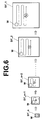
- FIG. 4 shows a processing flow in the detector
- FIG. 5 is a drawing for explaining calculation of characteristic quantities in a weak classifier
- FIG. 6 shows switching of resolution-converted images as targets of face detection and movement of a sub-window therein
- FIG. 7 is a flow chart showing processing in the face detection system
- FIG. 8 is a flow chart showing a learning method for the detector
- FIG. 9 shows a histogram of a weak classifier for a conventional 2-class problem
- FIG. 10 shows a histogram which is employed as a criterion for judging whether an image represents a predetermined object
- FIG. 11 shows how histograms are generated for respective types of sample images
- FIG. 12 shows a multi-dimensional histogram
- FIG. 13 shows the case where a score for an object as a correct answer and a score for an object as an incorrect answer are both positive;
- FIG. 14 shows basis vectors
- FIG. 15 shows a score vector
- the embodiment is a face detection system adopting the method of the present invention for detecting objects, and detects a face in a digital image regardless of a direction (out-plane direction), a position, a size, and a direction of rotation (orientation; in-plane direction) thereof.
- FIG. 1 is a block diagram showing the configuration of a face detection system 1 .
- the face detection system 1 comprises a multi-resolution conversion unit 10 , a normalization unit 20 , a face detection unit 30 , and a redundant detection judgment unit 40 .
- the face detection unit 30 detects an image representing a face (hereinafter referred to as a face image S 2 ) in each of the resolution-converted images in the image group S 1 ′ by carrying out the face detection processing thereon.
- the redundant detection judgment unit 40 obtains a face image S 3 without redundant face detection by judging whether the same face has been detected as the face images S 2 in the resolution-converted images, based on a position thereof.
- the multi-resolution conversion unit 10 obtains a normalized input image S 0 ′ by normalizing the input image S 0 into a predetermined resolution (image size) such as a rectangular image whose shorter sides respectively have 416 pixels, through conversion of the resolution of the input image S 0 .
- a predetermined resolution image size
- the multi-resolution conversion unit 10 By further carrying out the resolution conversion on the normalized input image S 0 ′, the multi-resolution conversion unit 10 generates the resolution-converted images in the different resolutions, for obtaining the resolution-converted image group S 1 .
- the resolution-converted image group S 1 is generated for the following reason. A size of a face included in an input image is generally unknown.
- a size of face (image size) to be detected is fixed to a predetermined size, in relation to a detector generation method that will be described later. Therefore, in order to detect faces in various sizes, partial images of a predetermined size are cut sequentially in each of the resolution-converted images while positions of the partial images are shifted therein. Whether each of the partial images is a face image or a non-face image is then judged. More specifically, as shown in FIG. 2 , the normalized input image S 0 ′ is used as the resolution-converted image S 1 _ 1 .
- the resolution-converted image S 1 _ 1 Based on the resolution-converted image S 1 _ 1 is generated the resolution-converted image S 1 _ 2 in the size of 2 to the power of ⁇ 1 ⁇ 3 of the resolution-converted image S 1 _ 1 .
- the resolution-converted image S 1 _ 2 Based on the resolution-converted image S 1 _ 2 is generated the resolution-converted image S 1 _ 3 in the size of 2 to the power of ⁇ 1 ⁇ 3 of the resolution-converted image S 1 _ 2 (that is, in the size of 2 to the power of ⁇ 2 ⁇ 3 of the resolution-converted image S 1 _ 1 ).
- the resolution-converted images S 1 _ 1 to S 1 _ 3 are respectively subjected to size reduction to 1 ⁇ 2, and images generated by the reduction are further reduced to 1 ⁇ 2.
- the resolution-converted images S 1 _ 1 has the rectangular shape whose shorter sides respectively have 416 pixels
- the resolution-converted images S 1 _ 2 , S 1 _ 3 and so on have rectangular shapes whose shorter sides respectively have 330 pixels, 262 pixels, 208 pixels, 165 pixels, 131 pixels, 104 pixels, 82 pixels, 65 pixels, and so on.
- the resolution-converted images reduced from the resolution-converted image S 1 _ 1 to every 2 to the power of ⁇ 1 ⁇ 3 can be generated.
- the images generated without pixel value interpolation tend to keep characteristics of the original image. Therefore, accuracy improvement is expected in the face detection processing, which is preferable.
- the normalization unit 20 carries out normalization processing on each of the images in the resolution-converted image group S 1 . More specifically, the normalization processing may be processing for converting the pixel values in the entire image according to a conversion curve (a look-up table) for causing the pixel values to be subjected to inverse Gamma transformation (that is, multiplication to the power of 2.2) in the sRGB color space followed by logarithmic conversion. This processing is carried out for the following reason.
- an image obtained by a device such as a general digital camera is in the sRGB color space.
- the sRGB color space is an internationally standardized color space wherein hue, saturation and the like are defined for consolidating differences in color reproduction among devices.
- the reflectance ratios alone of the subject which are not dependent on the intensity L of the light source, can be evaluated appropriately.
- the face detection unit 30 carries out the face detection processing on each of the images in the resolution-converted image group S 1 ′ having been subjected to the normalization processing carried out by the normalization unit 20 , and detects the face image S 2 in each of the resolution-converted images.
- the face detection unit 30 comprises a detection control unit 31 , a resolution-converted image selection unit 32 , a sub-window setting unit 33 , and a detector 34 .
- the detection control unit 31 mainly carries out sequence control in the face detection processing by controlling each of the units.
- the resolution-converted image selection unit 32 sequentially selects from the resolution-converted image group S 1 ′ one of the resolution-converted images in order of smaller size to be subjected to the face detection processing.
- the sub-window setting unit 33 sets a sub-window for cutting each partial image W as a target of judgment of face or non-face image in the resolution-converted image selected by the resolution-converted image selection unit 32 while sequentially changing a position of the sub-window.
- the detector 34 judges whether the partial image W having been cut is a face image.
- the detection control unit 31 controls the resolution-converted image selection unit 32 and the sub-window setting unit 33 for carrying out the face detection processing on each of the images in the resolution-converted image group S 1 ′.
- the detection control unit 31 appropriately instructs the resolution-converted image selection unit 32 to select the resolution-converted image to be subjected to the processing and notifies the sub-window setting unit 33 of a condition of sub-window setting.
- the detection control unit 31 also outputs a result of the detection to the redundant detection judgment unit 40 .
- the resolution-converted image selection unit 32 sequentially selects the resolution-converted image to be subjected to the face detection processing in order of smaller size (that is, in order of coarse resolution) from the resolution-converted image group S 1 ′, under control of the detection control unit 31 .
- the method of face detection in this embodiment is a method of detecting a face in the input image S 0 by judging whether each of the partial images W cut sequentially in the same size from each of the resolution-converted images is a face image. Therefore, the resolution-converted image selection unit 32 sets a size of face to be detected in the input image S 0 at each time of detection, which is equivalent to changing the size of face to be detected from a larger size to a smaller size.
- the sub-window setting unit 33 sequentially sets the sub-window according to the sub-window setting condition set by the detection control unit 31 in the resolution-converted image selected by the resolution-converted image selection unit 32 while sequentially moving the sub-window therein. For example, in the selected resolution-converted image, the sub-window setting unit 33 sequentially sets the sub-window for cutting the partial image W in the predetermined size (that is, 32 ⁇ 32 pixels) at a position on a line along which the resolution-converted image is scanned two-dimensionally, while rotating the resolution-converted image in 360 degrees in the plane of the image.
- the sub-window setting unit 33 outputs the partial images W to the detector 34 .
- the detector 34 calculates characteristic quantities related to difference in the pixel values (luminance) between predetermined positions, as at least one of characteristic quantities related to distribution of the pixel values in the partial image W. By using the characteristic quantities, the detector 34 judges whether the partial image W represents a face in any one of predetermined directions or a non-face object. For example, the detector 34 can make judgment on 5 types of faces, namely a front-view face, a left profile, a right profile, a half-left profile, and a half-right profile. The face directions may be categorized further. Since the detector 34 is to judge an image representing a face in an arbitrary face direction, an image of face in any direction and orientation can be judged.
- the configuration of the detector 34 , a training (generation) method therefore, and a procedure carried out therein are described next.
- a case of 3-class problem is described. More specifically, the case is described where the detector 34 judges the partial image W as any one of 3 objects comprising a “front-view face”, a “profile”, and a “non-face” object.
- FIG. 3 shows the configuration of the detector 34 .
- the detector 34 comprises weak classifiers WC connected in order of effectiveness for judgment selected from more weak classifiers through training that will be described later.
- Each of the weak classifiers WC calculates the characteristic quantities from the partial image W according to a predetermined algorithm specific thereto, and finds a score vector ⁇ s> representing a probability that the partial image W represents a “front-view face”, a probability that the partial image W represents a “profile”, and a probability that the partial image W represents a “non-face” object, based on the characteristic quantities and a 2-dimensional histogram that will be described later.
- the detector 34 judges which one of the objects the partial image W represents, by evaluating the score vector ⁇ s> obtained from all or a part of the weak classifiers WC.
- FIG. 8 is a flow chart showing the method of training for the detector 34 .
- sample images normalized to have the predetermined size such as 32 ⁇ 32 pixels are used.
- the sample images needs to be prepared for the types corresponding to the number of classes to be judged.
- front face sample images representing front-view faces, profile sample images representing profiles, and non-face sample images representing non-face objects are prepared.
- the orientations of the faces are substantially the same in the front face sample images and the profile sample images.
- Each of the sample images has been subjected to the same processing as the normalization processing carried out by the normalization unit 20 , and a weight (a degree of importance) has been assigned thereto.
- the weak classifiers are generated for respective pair groups of a plurality of types, each of which uses 2 predetermined points as one pair set in the plane of each of the sample images and in the planes of reduced images thereof (Step S 22 ).
- Each of the weak classifiers provides a criterion for judging whether the partial image W is a front-view face, or a profile, or a non-face object by using a combination of the pixel value (luminance) differences each of which is calculated between the 2 points comprising one of the pairs in one of the pair groups set in the planes of the partial image W cut by the sub-window and the reduced images thereof.
- a multi-dimensional histogram regarding the combination of the pixel value differences is used as a basis for a score table for the corresponding weak classifier.
- the 2 points comprising each of the pairs in one of the pair groups used for generation of the classifier are P 1 and P 2 , P 1 and P 3 , P 4 and P 5 , P 4 and P 6 , and P 6 and P 7 in the front-face sample images.
- the point P 1 is located at the center of the right eye in each of the face sample images while the point P 2 is located in the right cheek therein.
- the point P 3 is located between the eyebrows.
- the point P 4 is located at the center of the right eye in the reduced image of 16 ⁇ 16 pixels generated through 4-neighbor averaging (which will be described later) of the corresponding sample image while the point P 5 is located in the right cheek therein.
- the point P 6 is located in the forehead in the reduced image of 8 ⁇ 8 pixels generated through further 4-neighbor averaging while the point P 7 is located on the mouth therein. Coordinate positions of the 2 points comprising each of the pairs in one of the pair groups used for generation of the corresponding classifier are the same for all the sample images.
- the combination of the pixel value differences is found for the 5 pairs, and a histogram W 1 ( x ) thereof is generated where x refers to a value corresponding to the combination of the pixel value differences each of which is calculated between the 2 points in each of the pairs.
- histograms W 2 ( x ) and W 3 ( x ) are generated.
- the profile sample images and the non-face sample images are used the same positions as the positions of the predetermined 2 points (represented by the same reference codes P 1 to P 7 ) in each of the pairs in each of the face sample images.
- a two-dimensional histogram shown in FIG. 12 is then generated by combining the 3 histograms W 1 ( x ) to W 3 ( x ) according to the following equation.
- a vector ⁇ h(x)> is a two-dimensional histogram and vectors ⁇ e 1 >, ⁇ e 2 >, and ⁇ e 3 > are basis vectors.
- the two-dimensional histogram h(x) is the score vector ⁇ s> itself in the case where the value corresponding to the combination of the characteristic quantities is x.
- the inner product of the score vector ⁇ s> and the basis vector ⁇ e 1 > is a score SC 1 representing the probability of front-view face while the inner product of the score vector ⁇ s> and the basis vector ⁇ e 2 > is a score SC 2 representing the probability of profile.
- the inner product of the score vector ⁇ s> and the basis vector ⁇ e 3 > is a score SC 3 representing the probability of non-face object.
- each of the weak classifiers WC in the form of the histogram is generated for the combination of the pixel-value differences each of which is calculated between the 2 predetermined points in each of the pairs comprising each of the pair groups of the different types.
- the weak classifier WC that is most effective for the judgment is selected. This selection is carried out in consideration of the weight for each of the sample images. In this example, a weighted superiority is examined for each of the weak classifiers, and the weak classifier achieving the highest superiority is selected (Step S 23 ). More specifically, the weight for each of the sample images is 1/M at Step S 23 carried out for the first time. Therefore, superiority becomes higher as the score for the object as the correct answer among a front-view face, a profile, and a non-face object becomes larger than the scores for the incorrect answers. Consequently, the most effective classifier WC is selected as the classifier having the highest superiority regarding all the sample images.
- Step S 23 carried out for the second time after Step S 25 whereat the weight is updated for each of the sample images as will be described later, the sample images have the weights that are 1/M, larger than 1/M, and smaller than 1/M.
- the sample images whose weights are larger than 1/M contribute more to evaluation of the superiority than the sample images whose weights are 1/M. Therefore, at Step S 23 carried out for the second time or later, correct judgment of the sample images of the larger weights is more important than correct judgment of the sample images of the smaller weights. More specifically, the two-dimensional histogram ⁇ hk (x)> representing the weak classifier WC of the highest superiority is extracted according to the following equation where k refers to the number of repetition of execution of Step S 23 .
- Xi refers to a value corresponding to the combination of the characteristic quantities found from each of the sample images
- ⁇ ei> is the basis vector corresponding to the object as the correct answer among a front-view face, a profile, or a non-face object in the corresponding sample image (hereinafter referred to as the correct object) while ⁇ ej> is the basis vector corresponding to each of the objects as the incorrect answers (hereinafter referred to as the incorrect objects).
- Step S 24 Judgment is then made as to whether the sum of the score calculated by the selected weak classifiers WC for the correct object among a front-view face, a profile, or a non-face object in the sample images exceeds the sum of the scores for the incorrect objects or as to whether the number of repetition of Step S 23 reaches a predetermined number (Step S 24 ). More specifically, whether either one of the following conditions is satisfied is judged:
- Step S 23 the image can be judged with a sufficiently high probability as a front-view face, a profile, or a non-face object by the weak classifiers having been selected. Therefore, the training ends. In the case where the conditions are not satisfied, the procedure goes to Step S 26 for selecting an additional one of the classifiers WC to be used in combination with the classifiers having been selected.
- Step S 26 the weak classifier WC selected at the immediately preceding Step S 23 is excluded so that the same classifier is not selected again.
- the weights are then increased for the sample images for which the score has not been calculated with superiority by the weak classifier selected at the immediately preceding Step S 23 while the weights for the sample images for which the score has been calculated with sufficient superiority are decreased (Step S 25 ). More specifically, the weights are updated according to the following equation:
- the weights are decreased for the sample images if the score for the correct object (for example, the inner product represented by ⁇ hk> ⁇ e 2 > in the case where Object 2 is the correct object) is large.
- the score is a negative value
- the weights are increased.
- FIG. 13 the case may happen where the score for the correct object (Object 2 in FIG. 13 ) and the score for either one of the remaining objects (Object 1 in FIG. 13 ) are both positive. Therefore, an amount obtained by projection onto a direction appropriate for judgment of the objects (that is, ⁇ e 1 >- ⁇ e 2 > representing a side) is used for updating the corresponding weight.
- the weights are increased or decreased for enhancing an effect of the combination of the weak classifiers WC by putting emphasis on selecting the weak classifier WC enabling calculation of the score with superiority on the images that have not been calculated with superiority by the weak classifiers WC having been selected.
- Step S 23 the procedure then returns to Step S 23 whereat the weak classifier WC that is the most effective among the remaining classifiers is selected with reference to the weighted superiority.
- Step S 24 If either one of the predetermined conditions is satisfied at Step S 24 after selection of the weak classifier WC appropriate for judgment of the correct object (that is, a front-view face, or a profile, or a non-face object) corresponding to the combination of the pixel-value differences each of which is calculated between the 2 predetermined points comprising each of the pairs in a specific one of the pair groups through repetition of the procedure from Step S 23 to Step S 26 , the types of the weak classifiers WC used for the face detection and conditions therefore are confirmed (Step S 27 ), and the training is completed.
- the selected weak classifiers WC are linearly connected in order of higher weighted superiority, and the weak classifiers WC comprise the detector 34 .
- the two-dimensional histogram obtained for each of the weak classifiers WC is used as the score vector for calculating the scores for a front-view face, a profile, and a non-face object according to the combination of the pixel-value differences.
- FIG. 4 is a flow chart showing the procedure carried out in the detector 34 .
- the first weak classifier WC calculates the value x as a characteristic quantity (Step S 1 ).
- the first weak classifier WC carries out the 4-neighbor averaging on the partial image W of the predetermined size such as 32 ⁇ 32 pixels.
- the 4-neighbor averaging refers to processing wherein the image is divided into blocks of 2 ⁇ 2 pixels and a mean value of the values of the 4 pixels in each of the blocks is used as a pixel value corresponding to the block. In this manner, the reduced images of 16 ⁇ 16 pixels and 8 ⁇ 8 pixels are obtained.
- the difference value in the pixel values is calculated between the two points in each pair comprising one of the pair groups, and the combination of the difference values is used as the characteristic quantities.
- the two predetermined points in each of the pairs are predetermined two points aligned vertically or horizontally in each of the images so as to reflect a characteristic of density of a face therein, for example.
- the value corresponding to the combination of the difference values (the characteristic quantities) is found as the characteristic quantity x.
- the score vector ⁇ s> is calculated based on the two-dimensional histogram thereof (Step S 2 ).
- a cumulative score vector ⁇ ss> is then calculated by adding the score vector to the score vector handed over from the preceding weak classifier (Step S 3 ). Since the first weak classifier WC does not have the score vector handed over thereto, the score vector calculated by the first weak classifier is used as the cumulative score vector ⁇ ss> as it is.
- the scores SC 1 , SC 2 , and SC 3 respectively representing the probabilities of the partial image W being an image of front-view face, profile, and non-face object are calculated as the inner products between the score vector ⁇ ss> and each of the basis vectors ⁇ e 1 >, ⁇ e 2 >, and ⁇ e 3 >.
- Step S 4 Whether any one of the scores SC 1 , SC 2 , or SC 3 exceeds a predetermined threshold value is judged (Step S 5 ). In other words, whether the condition SC 1 >Th 1 or whether the condition SC 2 >Th 2 or whether the condition SC 3 >Th 3 is satisfied is judged. In the case where the condition SC>Th 1 is satisfied, the partial image W is judged to be an image representing a front-view face. In the case where the condition SC 2 >Th 2 is satisfied, the partial image W is judged to be an image representing a profile. The partial image W is judged to be a non-face image in the case where the condition SC 3 >Th 3 is satisfied (Step S 6 ). The procedure ends in these cases.
- Step S 7 whether the next weak classifier WC exists is judged. If a result of judgment at Step S 6 is affirmative, the cumulative score vector ⁇ ss> is handed over to the next weak classifier WC for causing the next weak classifier to carry out the judgment (Step S 9 ). If the result of the judgment at Step S 7 is negative, the partial image W is judged to be an image representing the object corresponding to the highest score (Step S 8 ) to end the procedure.
- the redundant detection judgment unit 40 carries out processing for classifying the face images representing the same face in the images in the resolution-converted image group S 1 ′ (that is, the face images detected more than once) into one face image according to position information on the true face images S 2 detected by the face detection unit 30 , and outputs the true face image S 3 detected in the input image S 0 .
- the size of face detected by the detector compared to the size of the partial image W has some margin although the margin depends on the training method. Therefore, this processing is carried out because the images representing the same face are sometimes detected more than once in the resolution-converted images whose resolutions are close to each other.
- the sub-window setting unit 33 serves as the partial image cutting means and the detector 34 serves as the judgment means of the present invention.
- FIG. 7 is a flow chart showing the procedure.
- the input image S 0 is fed to the multi-resolution conversion unit 10 (Step S 11 ), and the image S 0 ′ is generated in the predetermined size converted from the size of the input image S 0 .
- the resolution-converted image group S 1 is generated comprising the resolution-converted images having the sizes (resolutions) reduced to every 2 to the power of ⁇ 1 ⁇ 3 from the image S 0 ′ (Step S 12 ).
- the normalization unit 20 carries out the normalization processing for reducing the variance of contrast in each of the resolution-converted images to obtain the normalized resolution-converted image group S 1 ′ (Step S 13 ).
- the resolution-converted image selection unit 32 instructed by the detection control unit 31 sequentially selects the resolution-converted image to be subjected to the face detection processing in order of smaller image size from the resolution-converted image group S 1 ′.
- the resolution-converted image is selected in order of S 1 ′_n, S 1 ′_n ⁇ 1, . . . , and S 1 ′_ 1 (hereinafter referred to as S 1 ′ _i) from the resolution-converted image group S 1 ′ (Step S 14 ).
- the detection control unit 31 sets the sub-window setting condition for the sub-window setting unit 33 .
- the sub-window setting unit 33 sets the sub-window in the resolution-converted image S 1 ′_i while sequentially moving the sub-window for cutting the partial image W of the predetermined size (Step S 15 ), and inputs the partial image W to the detector 34 (Step S 16 ).
- the detector 34 judges whether the partial image W input thereto is an image of any one of the 3 objects, and the detection control unit 31 obtains the result R of the judgment (Step S 17 ).
- the detection control unit 31 judges whether the partial image W currently cut is the partial image to be subjected last to the detection (Step S 18 ). In the case where a result of the judgment is affirmative, the procedure goes to Step S 19 . Otherwise, the procedure returns to Step S 15 for newly cutting the partial image W. In this manner, the face image in the resolution-converted image S 1 ′_i is extracted.
- the detection control unit 31 judges whether the resolution-converted image S 1 ′_i currently selected is the image to be subjected last to the detection (Step S 18 ). In the case where a result of the judgment is affirmative, the detection processing ends, and the redundant detection judgment is carried out (Step S 19 ). Otherwise, the procedure returns to Step S 14 whereat the resolution-converted image selection unit 32 selects the resolution-converted image S 1 ′_i ⁇ 1 whose size is larger than the currently selected resolution-converted image S 1 ′_i by one step, for further carrying out the face detection.
- FIG. 6 shows selection of the resolution-converted images in order of smaller size, and face detection is carried out therein.
- the redundant detection judgment unit 40 classifies the face images S 2 detected more than once into one face image, and the true face image S 3 detected in the input image S 0 is output.
- the face detection system in the method of detecting a face as a detection target in an input image by judging whether each of the partial images cut at a different position in the input image represents a predetermined face by use of the weak classifiers that evaluate whether a target image is the predetermined face based on the histogram of the values of the characteristic quantities calculated from the sample images representing the predetermined face as a predetermined object, the histogram is extended to multi-dimensions and the criterion for the evaluation is the multi-dimensional histogram representing the histograms for the different types of faces in the form of the vector.
- the faces of the different types can be learned by the detector through the training carried out only once. Therefore, the training can be carried out efficiently.
- each of the detectors is a one-dimensional histogram, and histograms for 3 dimensions are necessary. Meanwhile, in the method of the present invention, the histograms for only 2 dimensions are sufficient. In general, in order to completely solve an N-body problem by detectors for a 2-body problem, the histograms for dimensions of all combinations (NC2) are necessary. However, in the method of the present invention, only the histograms for the dimensions of N ⁇ 1 are sufficient.
- the total amount of the histograms depends not only on the number of dimensions but also the number of the weak classifiers.
- the number of combinations (NC2) increases as the power of N while the number of (N ⁇ 1) shows a linear increase of N. Therefore, if N is large, the increase in the total amount of the histograms of the weak classifiers can be compensated.
- a program for causing a computer to execute the procedure carried out by the objects detection apparatus of the present invention in the face detection system is also an embodiment of the present invention.
- a computer-readable recording medium storing the program is also an embodiment of the present invention.
Landscapes
- Engineering & Computer Science (AREA)
- Theoretical Computer Science (AREA)
- Physics & Mathematics (AREA)
- Health & Medical Sciences (AREA)
- General Physics & Mathematics (AREA)
- Oral & Maxillofacial Surgery (AREA)
- Multimedia (AREA)
- General Health & Medical Sciences (AREA)
- Evolutionary Computation (AREA)
- Computer Vision & Pattern Recognition (AREA)
- Artificial Intelligence (AREA)
- Computing Systems (AREA)
- Software Systems (AREA)
- Databases & Information Systems (AREA)
- Geometry (AREA)
- Medical Informatics (AREA)
- Human Computer Interaction (AREA)
- Data Mining & Analysis (AREA)
- Life Sciences & Earth Sciences (AREA)
- Bioinformatics & Cheminformatics (AREA)
- Bioinformatics & Computational Biology (AREA)
- Evolutionary Biology (AREA)
- General Engineering & Computer Science (AREA)
- Image Analysis (AREA)
Abstract
Description
y Gen=(W + −W −)/(W + +W −) (2)
w 1(i)=1/M (9)
w1(i)=1/M (9)
(for a 3-class problem corresponding to N=3)
where a vector <h(x)> is a two-dimensional histogram and vectors <e1>, <e2>, and <e3> are basis vectors.
where K refers to the number of repetition of Step S23 at the current stage. In the case where either one of the above-described conditions is satisfied, the image can be judged with a sufficiently high probability as a front-view face, a profile, or a non-face object by the weak classifiers having been selected. Therefore, the training ends. In the case where the conditions are not satisfied, the procedure goes to Step S26 for selecting an additional one of the classifiers WC to be used in combination with the classifiers having been selected.
Claims (12)
Applications Claiming Priority (3)
| Application Number | Priority Date | Filing Date | Title |
|---|---|---|---|
| JP2005230704A JP4588575B2 (en) | 2005-08-09 | 2005-08-09 | Method, apparatus and program for detecting multiple objects in digital image |
| JP230704/2005 | 2005-08-09 | ||
| JP2005-230704 | 2005-08-09 |
Publications (2)
| Publication Number | Publication Date |
|---|---|
| US20070036431A1 US20070036431A1 (en) | 2007-02-15 |
| US7760940B2 true US7760940B2 (en) | 2010-07-20 |
Family
ID=37742593
Family Applications (1)
| Application Number | Title | Priority Date | Filing Date |
|---|---|---|---|
| US11/500,982 Active 2029-05-20 US7760940B2 (en) | 2005-08-09 | 2006-08-09 | Method, apparatus, and program for detecting objects in digital image |
Country Status (2)
| Country | Link |
|---|---|
| US (1) | US7760940B2 (en) |
| JP (1) | JP4588575B2 (en) |
Cited By (3)
| Publication number | Priority date | Publication date | Assignee | Title |
|---|---|---|---|---|
| US20100034459A1 (en) * | 2008-08-08 | 2010-02-11 | Kabushiki Kaisha Toshiba | Method and apparatus for calculating features of image data |
| US20120070033A1 (en) * | 2010-01-29 | 2012-03-22 | Rochester Institute Of Technology | Methods for object-based identification, sorting and ranking of target detections and apparatuses thereof |
| US20160148071A1 (en) * | 2014-11-24 | 2016-05-26 | Texas Instruments Incorporated | Systems and methods for object detection |
Families Citing this family (10)
| Publication number | Priority date | Publication date | Assignee | Title |
|---|---|---|---|---|
| JP2008108024A (en) * | 2006-10-25 | 2008-05-08 | Matsushita Electric Ind Co Ltd | Image processor and imaging device |
| KR100919167B1 (en) * | 2007-08-16 | 2009-09-28 | 한국과학기술원 | System and method for histogram equalization |
| JP2009118009A (en) * | 2007-11-02 | 2009-05-28 | Sony Corp | Imaging apparatus, method for controlling same, and program |
| JP4710979B2 (en) | 2009-01-09 | 2011-06-29 | ソニー株式会社 | Object detection device, learning device, object detection method and program |
| JP2011090466A (en) * | 2009-10-21 | 2011-05-06 | Sony Corp | Information processing apparatus, method, and program |
| JP5748472B2 (en) * | 2010-12-15 | 2015-07-15 | 富士フイルム株式会社 | Object discrimination device, method, and program |
| US9251588B2 (en) | 2011-06-20 | 2016-02-02 | Nokia Technologies Oy | Methods, apparatuses and computer program products for performing accurate pose estimation of objects |
| US10127503B2 (en) * | 2015-10-21 | 2018-11-13 | International Business Machines Corporation | Generating multidimensional combination data |
| EP3540634A1 (en) * | 2018-03-13 | 2019-09-18 | InterDigital CE Patent Holdings | Method for audio-visual events classification and localization and corresponding apparatus computer readable program product and computer readable storage medium |
| WO2021113235A1 (en) * | 2019-12-02 | 2021-06-10 | University Of Utah Research Foundation | Medical image synthesis for motion correction using generative adversarial networks |
Citations (12)
| Publication number | Priority date | Publication date | Assignee | Title |
|---|---|---|---|---|
| US4323880A (en) * | 1974-07-22 | 1982-04-06 | The United States Of America As Represented By The Secretary Of The Navy | Automatic target screening |
| US4972193A (en) * | 1988-08-09 | 1990-11-20 | The General Electric Company, P.L.C. | Target recognition |
| US5446543A (en) * | 1992-07-24 | 1995-08-29 | Kabushiki Kaisha Toshiba | Method and apparatus for extracting a pattern of color from an object using a neural network |
| US6154559A (en) * | 1998-10-01 | 2000-11-28 | Mitsubishi Electric Information Technology Center America, Inc. (Ita) | System for classifying an individual's gaze direction |
| US20020102024A1 (en) | 2000-11-29 | 2002-08-01 | Compaq Information Technologies Group, L.P. | Method and system for object detection in digital images |
| US6675174B1 (en) * | 2000-02-02 | 2004-01-06 | International Business Machines Corp. | System and method for measuring similarity between a set of known temporal media segments and a one or more temporal media streams |
| US6754367B1 (en) * | 1999-09-30 | 2004-06-22 | Hitachi Denshi Kabushiki Kaisha | Method and apparatus for automatically detecting intrusion object into view of image pickup device |
| US6865295B2 (en) * | 2001-05-11 | 2005-03-08 | Koninklijke Philips Electronics N.V. | Palette-based histogram matching with recursive histogram vector generation |
| US20050129276A1 (en) * | 2003-12-11 | 2005-06-16 | Haynes Simon D. | Object detection |
| US20050180639A1 (en) * | 2004-02-17 | 2005-08-18 | Trifonov Mikhail I. | Iterative fisher linear discriminant analysis |
| US20060140455A1 (en) * | 2004-12-29 | 2006-06-29 | Gabriel Costache | Method and component for image recognition |
| US7123754B2 (en) * | 2001-05-22 | 2006-10-17 | Matsushita Electric Industrial Co., Ltd. | Face detection device, face pose detection device, partial image extraction device, and methods for said devices |
Family Cites Families (3)
| Publication number | Priority date | Publication date | Assignee | Title |
|---|---|---|---|---|
| JPS6057475A (en) * | 1983-09-07 | 1985-04-03 | Toshiba Corp | Pattern recognizing system |
| JP4338560B2 (en) * | 2003-04-14 | 2009-10-07 | 富士フイルム株式会社 | Image feature portion extraction method, feature portion extraction program, imaging apparatus, and image processing apparatus |
| JP4510556B2 (en) * | 2003-09-09 | 2010-07-28 | 富士フイルム株式会社 | Object identification device and method, and program |
-
2005
- 2005-08-09 JP JP2005230704A patent/JP4588575B2/en active Active
-
2006
- 2006-08-09 US US11/500,982 patent/US7760940B2/en active Active
Patent Citations (12)
| Publication number | Priority date | Publication date | Assignee | Title |
|---|---|---|---|---|
| US4323880A (en) * | 1974-07-22 | 1982-04-06 | The United States Of America As Represented By The Secretary Of The Navy | Automatic target screening |
| US4972193A (en) * | 1988-08-09 | 1990-11-20 | The General Electric Company, P.L.C. | Target recognition |
| US5446543A (en) * | 1992-07-24 | 1995-08-29 | Kabushiki Kaisha Toshiba | Method and apparatus for extracting a pattern of color from an object using a neural network |
| US6154559A (en) * | 1998-10-01 | 2000-11-28 | Mitsubishi Electric Information Technology Center America, Inc. (Ita) | System for classifying an individual's gaze direction |
| US6754367B1 (en) * | 1999-09-30 | 2004-06-22 | Hitachi Denshi Kabushiki Kaisha | Method and apparatus for automatically detecting intrusion object into view of image pickup device |
| US6675174B1 (en) * | 2000-02-02 | 2004-01-06 | International Business Machines Corp. | System and method for measuring similarity between a set of known temporal media segments and a one or more temporal media streams |
| US20020102024A1 (en) | 2000-11-29 | 2002-08-01 | Compaq Information Technologies Group, L.P. | Method and system for object detection in digital images |
| US6865295B2 (en) * | 2001-05-11 | 2005-03-08 | Koninklijke Philips Electronics N.V. | Palette-based histogram matching with recursive histogram vector generation |
| US7123754B2 (en) * | 2001-05-22 | 2006-10-17 | Matsushita Electric Industrial Co., Ltd. | Face detection device, face pose detection device, partial image extraction device, and methods for said devices |
| US20050129276A1 (en) * | 2003-12-11 | 2005-06-16 | Haynes Simon D. | Object detection |
| US20050180639A1 (en) * | 2004-02-17 | 2005-08-18 | Trifonov Mikhail I. | Iterative fisher linear discriminant analysis |
| US20060140455A1 (en) * | 2004-12-29 | 2006-06-29 | Gabriel Costache | Method and component for image recognition |
Non-Patent Citations (2)
| Title |
|---|
| Chapelle, Olivier, Patrick Haffner, and Vladimir Vapnik. "SVMs for Histogram-Based Image Classification." IEEE Transactions on Neural Networks 3(1999): 1-11. Print. * |
| Oja, Erkki, and Kimmo Valkealahti. "Co-occurrence map : Quantizing multidimensional texture histograms." Pattern Recognition Letters 17(1996): 723-730. Print. * |
Cited By (6)
| Publication number | Priority date | Publication date | Assignee | Title |
|---|---|---|---|---|
| US20100034459A1 (en) * | 2008-08-08 | 2010-02-11 | Kabushiki Kaisha Toshiba | Method and apparatus for calculating features of image data |
| US8582880B2 (en) * | 2008-08-08 | 2013-11-12 | Kabushiki Kaisha Toshiba | Method and apparatus for calculating features of image data |
| US20120070033A1 (en) * | 2010-01-29 | 2012-03-22 | Rochester Institute Of Technology | Methods for object-based identification, sorting and ranking of target detections and apparatuses thereof |
| US8897489B2 (en) * | 2010-01-29 | 2014-11-25 | Rochester Institute Of Technology | Methods for object-based identification, sorting and ranking of target detections and apparatuses thereof |
| US20160148071A1 (en) * | 2014-11-24 | 2016-05-26 | Texas Instruments Incorporated | Systems and methods for object detection |
| US9508018B2 (en) * | 2014-11-24 | 2016-11-29 | Texas Instruments Incorporated | Systems and methods for object detection |
Also Published As
| Publication number | Publication date |
|---|---|
| JP2007047975A (en) | 2007-02-22 |
| JP4588575B2 (en) | 2010-12-01 |
| US20070036431A1 (en) | 2007-02-15 |
Similar Documents
| Publication | Publication Date | Title |
|---|---|---|
| US7760940B2 (en) | Method, apparatus, and program for detecting objects in digital image | |
| US20070036429A1 (en) | Method, apparatus, and program for object detection in digital image | |
| US7689034B2 (en) | Learning method for detectors, face detection method, face detection apparatus, and face detection program | |
| US7359572B2 (en) | Automatic analysis and adjustment of digital images with exposure problems | |
| US7336819B2 (en) | Detection of sky in digital color images | |
| US7778483B2 (en) | Digital image processing method having an exposure correction based on recognition of areas corresponding to the skin of the photographed subject | |
| US7881494B2 (en) | Characteristic point detection of target object included in an image | |
| US7801337B2 (en) | Face detection method, device and program | |
| US7099510B2 (en) | Method and system for object detection in digital images | |
| US7957567B2 (en) | Method, apparatus, and program for judging faces facing specific directions | |
| US6516087B1 (en) | Method for real time correlation of stereo images | |
| US7634135B2 (en) | Image processing apparatus | |
| US9679370B2 (en) | Image processing device and image processing method | |
| US8155396B2 (en) | Method, apparatus, and program for detecting faces | |
| US20070041638A1 (en) | Systems and methods for real-time object recognition | |
| US20060203311A1 (en) | Automatic white balance method adaptive to digital color images | |
| JP2008117391A (en) | Method and apparatus for detecting faces in digital images | |
| US20070076954A1 (en) | Face orientation identifying method, face determining method, and system and program for the methods | |
| US20120121203A1 (en) | Image processing apparatus, image processing method, and computer program | |
| US20070189609A1 (en) | Method, apparatus, and program for discriminating faces | |
| US8571315B2 (en) | Information processing apparatus, information processing method, and program | |
| JP4795864B2 (en) | Feature point detection apparatus and method, and program | |
| US7388988B2 (en) | Systems and methods for processing boundary information of a graphical object | |
| Appiah et al. | Fast generation of image’s histogram using approximation technique for image processing algorithms | |
| JP2004246618A (en) | Method, device, and program for generating image used for collating in pattern recognition and pattern recognition using the image |
Legal Events
| Date | Code | Title | Description |
|---|---|---|---|
| AS | Assignment |
Owner name: FUJI PHOTO FILM CO., LTD., JAPAN Free format text: ASSIGNMENT OF ASSIGNORS INTEREST;ASSIGNOR:TERAKAWA, KENSUKE;REEL/FRAME:018173/0162 Effective date: 20060725 |
|
| AS | Assignment |
Owner name: FUJIFILM CORPORATION, JAPAN Free format text: ASSIGNMENT OF ASSIGNORS INTEREST;ASSIGNOR:FUJIFILM HOLDINGS CORPORATION (FORMERLY FUJI PHOTO FILM CO., LTD.);REEL/FRAME:018904/0001 Effective date: 20070130 Owner name: FUJIFILM CORPORATION,JAPAN Free format text: ASSIGNMENT OF ASSIGNORS INTEREST;ASSIGNOR:FUJIFILM HOLDINGS CORPORATION (FORMERLY FUJI PHOTO FILM CO., LTD.);REEL/FRAME:018904/0001 Effective date: 20070130 |
|
| STCF | Information on status: patent grant |
Free format text: PATENTED CASE |
|
| FEPP | Fee payment procedure |
Free format text: PAYOR NUMBER ASSIGNED (ORIGINAL EVENT CODE: ASPN); ENTITY STATUS OF PATENT OWNER: LARGE ENTITY |
|
| FPAY | Fee payment |
Year of fee payment: 4 |
|
| MAFP | Maintenance fee payment |
Free format text: PAYMENT OF MAINTENANCE FEE, 8TH YEAR, LARGE ENTITY (ORIGINAL EVENT CODE: M1552) Year of fee payment: 8 |
|
| MAFP | Maintenance fee payment |
Free format text: PAYMENT OF MAINTENANCE FEE, 12TH YEAR, LARGE ENTITY (ORIGINAL EVENT CODE: M1553); ENTITY STATUS OF PATENT OWNER: LARGE ENTITY Year of fee payment: 12 |