US7761237B2 - Method for quantification and mitigation for dip-induced azimuthal AVO - Google Patents
Method for quantification and mitigation for dip-induced azimuthal AVO Download PDFInfo
- Publication number
- US7761237B2 US7761237B2 US11/666,579 US66657905A US7761237B2 US 7761237 B2 US7761237 B2 US 7761237B2 US 66657905 A US66657905 A US 66657905A US 7761237 B2 US7761237 B2 US 7761237B2
- Authority
- US
- United States
- Prior art keywords
- dip
- azavo
- dipping
- seismic data
- attribute
- Prior art date
- Legal status (The legal status is an assumption and is not a legal conclusion. Google has not performed a legal analysis and makes no representation as to the accuracy of the status listed.)
- Active, expires
Links
Images


Classifications
-
- G—PHYSICS
- G01—MEASURING; TESTING
- G01V—GEOPHYSICS; GRAVITATIONAL MEASUREMENTS; DETECTING MASSES OR OBJECTS; TAGS
- G01V1/00—Seismology; Seismic or acoustic prospecting or detecting
- G01V1/28—Processing seismic data, e.g. analysis, for interpretation, for correction
- G01V1/32—Transforming one recording into another or one representation into another
-
- G—PHYSICS
- G01—MEASURING; TESTING
- G01V—GEOPHYSICS; GRAVITATIONAL MEASUREMENTS; DETECTING MASSES OR OBJECTS; TAGS
- G01V1/00—Seismology; Seismic or acoustic prospecting or detecting
- G01V1/28—Processing seismic data, e.g. analysis, for interpretation, for correction
- G01V1/36—Effecting static or dynamic corrections on records, e.g. correcting spread; Correlating seismic signals; Eliminating effects of unwanted energy
-
- G—PHYSICS
- G01—MEASURING; TESTING
- G01V—GEOPHYSICS; GRAVITATIONAL MEASUREMENTS; DETECTING MASSES OR OBJECTS; TAGS
- G01V2210/00—Details of seismic processing or analysis
- G01V2210/50—Corrections or adjustments related to wave propagation
- G01V2210/52—Move-out correction
-
- G—PHYSICS
- G01—MEASURING; TESTING
- G01V—GEOPHYSICS; GRAVITATIONAL MEASUREMENTS; DETECTING MASSES OR OBJECTS; TAGS
- G01V2210/00—Details of seismic processing or analysis
- G01V2210/60—Analysis
- G01V2210/63—Seismic attributes, e.g. amplitude, polarity, instant phase
-
- G—PHYSICS
- G01—MEASURING; TESTING
- G01V—GEOPHYSICS; GRAVITATIONAL MEASUREMENTS; DETECTING MASSES OR OBJECTS; TAGS
- G01V2210/00—Details of seismic processing or analysis
- G01V2210/60—Analysis
- G01V2210/63—Seismic attributes, e.g. amplitude, polarity, instant phase
- G01V2210/632—Amplitude variation versus offset or angle of incidence [AVA, AVO, AVI]
Definitions
- AVO Amplitude-Variation-with-Offset
- FIG. 1 b depicts seismic data recorded by the receiver R for several different values of the source-receiver distance 11 (called the offset), but each reflection event being from the same reflection point D.
- the receiver measures seismic amplitude as a function of the two-way traveltime for the seismic wave to travel down to D from S and then back up to R ( FIG. 1 a ).
- the traveltime is related to the depth of the reflection point by the geometry of the ray-path and the seismic wave velocity.
- the reflector 12 in FIG. 1 a is shown in FIG. 1 b at different traveltimes (the S-D-R distance), depending on offset. This is because the data have not yet been corrected by a standard seismic data processing procedure called normal moveout.
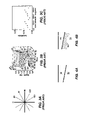
- FIG. 2 a illustrates the above-stated definition of azimuth, i.e., the angle ⁇ between the North direction and the line between the source S and receiver R.
- FIG. 2 b shows a flat response for reflection amplitude as a function of azimuth, which means the medium is azimuthally isotropic. Reflection amplitude, however, becomes azimuthally dependent when the formation beneath the reflection surface is azimuthally anisotropic due to, for example, containing aligned vertical fractures. Reflection amplitude vs. azimuth might then look something like FIG. 2 c . In such a case, the amplitude variation is called AzAVO (azimuthal AVO).
- Geophysicists perform AVO analysis to derive rock and fluid properties of the reservoir formation beneath the reflection boundary.
- AVO analysis See, for example, Smith, G. C. and Gidlow, P. M., “Weighted stacking for rock property estimation and detection of gas,” Geophys. Prosp ., Eur. Assn. Geosci. Eng., 35, 993-1014 (1987); Rutherford, S. R. and Williams, R. H., “Amplitude-versus-offset variations in gas sands,” Geophysics 54, 680-688 (1989); Castagna, J. P., Swan, H. W., and Foster, D.
- AzAVO can also occur when a formation is isotropic but is bounded on top by a dipping boundary surface. This phenomenon may be illustrated by a numerical example.
- seismic lines were shot along many azimuthal directions, as shown in FIG. 3 a (angular scale in degrees), over the simple earth model of FIG. 3 b .
- the figure depicts ray-paths from a shot position 31 being detected by many different receivers at 32 . Because seismic waves spread out, or diverge, as they travel, divergence corrections are necessary for restoring reflection amplitudes to represent the true reflection strength at the reflection boundary.
- the state-of-the-art processing does not properly restore amplitudes from dipping reflector because it assumes that rock formations such as 33 in FIG.
- FIG. 3 b are flat. It also neglects the amplitude correction for compensating the azimuth-dependent reflection angles.
- the resultant amplitude in addition to being offset (or, incident angle) dependent, also becomes azimuthally dependent ( FIG. 3 c ).
- This type of amplitude variation may be called “dip-induced” AzAVO to distinguish it from the AzAVO induced by anisotropy due to, for example, aligned vertical fractures.
- the dip-induced AzAVO contaminates seismic amplitude not only when formations are isotropic but also when formations are anisotropic.
- AzAVO inversion of 3-D seismic data without doing seismic migration. This method assumes rock formations are flat, and therefore the divergence correction applied does not compensate the dip-induced AzAVO.
- the method is preferable to the sector inversion method because it uses amplitude-offset-azimuth information of all traces simultaneously in the inversion to gain statistical power for fracture-attribute estimation. The inversion result, however, may also be ambiguous because the dip-induced AzAVO is not eliminated from the data.
- a method for compensating for dip-induced errors in Amplitude-Variation-with-Offset (AVO) attributes or in Azimuthal AVO (AzAVO) attributes derived from a 3-D seismic data volume obtained from a seismic survey of a dipping reservoir lying beneath isotropic overburden comprises (a) accounting for azimuth dependence of energy divergence in seismic wave reflected from the dipping reservoir; and (b) accounting for azimuth dependence of reflection angle reflected from the dipping reservoir in the 3-D seismic data volume.
- a method for compensating for dip-induced errors in AVO attributes derived from a 3-D seismic data volume obtained from a seismic survey of a dipping isotropic reservoir lying beneath isotropic overburden comprises the steps of: (a) applying Azimuthal AVO (AzAVO) inversion to the seismic data to generate four attribute data volumes A, B, B′ and ⁇ a corresponding to amplitude-offset-azimuth relationship of a hypothetical flat layer with aligned vertical fractures, where A and B are AzAVO equivalents of AVO intercept and slope attributes, respectively, B′ is an AzAVO attribute related to anisotropy intensity and ⁇ a is the azimuth of the aligned fractures; (b) calculating dip angles ⁇ at the reservoir's upper surface and multiplying cos ⁇ by A to obtain dip-compensated AVO intercept attribute A 0 for the actual dipping reservoir; (c) calculating dip-compensated AVO slope attribute B 0 for the actual dipping reservoir
- AzAVO Amplitude-Variation-with-Offset
- This method comprises the steps of: (a) calculating a dip angle ⁇ and a dip azimuth angle ⁇ 0 sample-by-sample from the 3-D seismic data volume; (b) calculating a scale factor for each sample in normal-moveout corrected common mid-point (CMP) gathers of the 3-D seismic data volume, the scale factor being determined to cause amplitudes of the 3-D seismic data volume to satisfy an AzAVO equation for a hypothetical flat anisotropic layer containing aligned fractures; (c) applying the scale factor to the 3-D seismic data sample-by-sample; and (d) inverting the AzAVO equation on CMP gathers of the scaled 3-D seismic data volume to generate four dip-compensated attribute data volumes A, B, B′ and ⁇ f for the actual dipping anisotropic reservoir, where A and B are AzAVO equivalents of Amplitude-Variation-with-Offset (AVO) intercept and slope attributes, respectively, B′ is an AzAVO attribute related to anisotropy
- the method comprises the steps of (a) applying AzAVO inversion to the 3-D seismic data volume to generate four attribute data volumes A, B, B′, and ⁇ 0 ′ corresponding to a hypothetical flat layer with aligned vertical fractures, where A and B are AzAVO equivalents of AVO intercept and slope attributes, respectively, B′ is an AzAVO attribute related to anisotropy intensity and ⁇ 0 ′ is the estimated azimuth of the aligned vertical fractures; (b) calculating dip angles ⁇ at the dipping anisotropic reservoir's upper surface and obtaining dip-compensated AzAVO intercept attribute A 0 for the actual dipping anisotropic reservoir by multiplying A by cos ⁇ ; (c) adding the B and B′ attributes at each spatial location on the actual dipping anisotropic reservoir's upper surface, and multiplying the sum by cos ⁇ ; (d) estimating dip-compensated AzAVO slope attribute B 0 for the actual dipping anisotropic reservoir; (e) subtracting B 0 from (B
- a method for estimating a magnitude of dip-induced error in calculated values of Amplitude-Variation-with-Offset (AVO) intercept and slope attributes derived from seismic data from a 3-D survey of a dipping isotropic reflector lying beneath isotropic overburden comprises the steps of (a) calculating a Magnitude quantity representative of the maximum amount of amplitude variation in the dip-induced AzAVO from
- FIG. 1 a illustrates the relationship between seismic raypath, shot, receiver, offset, and reflection angle in a horizontal stratified earth
- FIG. 2 a illustrates the definition of azimuth of a shot-receiver line
- FIG. 2 c illustrates that reflection amplitude become azimuth-dependent when the formation beneath the reflection surface is azimuthally anisotropic
- FIG. 3 a illustrates the geometry of azimuth shooting
- FIG. 3 b illustrates the numerical earth model and an example of raypaths along a shot line
- FIG. 3 c illustrates that reflection amplitude at a fixed offset is azimuthal dependent for the earth model of FIG. 3 b;
- FIG. 5 illustrates the linear relationship between reflection coefficient and the square of the sine of the reflection angle
- FIG. 7 is a three-dimensional (3-D) perspective diagram to aid in transforming ray-path geometry from a flat reflector to a dipping reflector;
- FIG. 8 is a flow chart indicating the primary steps of one embodiment of the present inventive method (Case 1) for compensating for a dipping isotropic reservoir;
- FIG. 9 is a flow chart indicating the primary steps of one embodiment of the present inventive method (Case 2) for compensating for a dipping anisotropic reservoir with oriented vertical fractures;
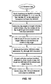
- FIG. 10 is a flow chart indicating the primary steps of one embodiment of the present inventive method (Case 3) for compensating for a dipping anisotropic reservoir with vertical fractures aligned perpendicular to the dip direction;
- FIGS. 11 a - 11 c show three parameter sections along a seismic line derived from AzAVO inversion
- FIG. 12 illustrates the procedure of adding two attributes to derive formation intrinsic values for the AVO slope attribute B 0 along a seismic line in a 3-D seismic data cube.
- the present invention is a method for quantifying and mitigating dip effects in both AVO analysis and AzAVO inversion.
- the inventive method uses the previously described CMP-based AzAVO-inversion method as the starting point. Equations are derived to describe AzAVO properties in the presence of formation dip for three cases: (1) an isotropic layer 18 (i.e., overburden) over a dipping, isotropic reservoir layer 19 as illustrated in FIG. 4 a , (2) an isotropic layer 14 over a dipping and anisotropic reservoir 15 with oriented vertical fractures 16 as illustrated in FIG. 4 b , and (3) a special sub-case of Case (2) when the fracture azimuth is perpendicular to the dip azimuth of the fractured formation (also illustrated by FIG. 4 b ).
- vertical fractures means the fractures are perpendicular to the dipping reflection surface above them.
- the fracture azimuth is defined as the angle between (a) the line formed by the intersection of the fracture plane with a horizontal plane, and (b) a reference direction that is typically geographic North. Dip azimuth is the angle between the dip direction of the formation and the North. Insights from these equations are used to quantify the impact of the dip effect and to develop simple and data-driven methods to remove the dip effect from AzAVO inversion.
- a 0 and B 0 are the intercept and slope, respectively, of the least-square-fit line 51 drawn through the R vs. sin 2 ⁇ cross-plot derived from seismic data. They are the AVO parameters (called “attributes”) used to derive the intrinsic lithology and fluid properties of the underlying reservoir formation (see, for example, the 1998 article by Castagna, et al.).
- the magnitude of the divergence is close to, and may be approximated by, the reciprocal of the travel distance along the raypath from shot point S to receiver R via reflection point D in FIG. 1 a .
- the reflection surface is horizontal (i.e., not dipping)
- the quantity div varies with the offset between the shot and the receiver ( FIG. 1 a ).
- the reflection amplitude is corrected for divergence prior to AVO analysis.
- equation (1) should be re-written to compensate for the change in divergence and reflection angle. (The embodiments of the present inventive method for all three cases described herein compensate seismic amplitudes for both sources of error.)
- the angular quantities ⁇ and ⁇ i can be approximately related by the following expression:
- ⁇ is the dip angle of the reflection formation 72 (i.e., the angle by which the formation surface deviates from horizontal)
- ⁇ is the azimuth angle of the shot-receiver (S-R) line
- ⁇ 0 is dip azimuth of the dipping formation (i.e., the direction 73 of maximum dip)
- ⁇ is the true reflection angle
- ⁇ i is the mid-point angle, i.e., the reflection angle that may be obtained by incorrectly assuming that the dipping, subsurface reflector plane 72 is parallel to the horizontal, surface plane 71 .
- O is the midpoint between source S and receiver R
- D is the reflection point on reflector 72
- M located vertically below O, is where the reflection point may be if reflect
- Equation (3) (4) is valid for dip angle up to approximately 20 degrees and reflection angle up to 30 degrees.
- Equation (6) describes the relationship between amplitude, dip angle of the reflecting formation, and the mid-point reflection angle ⁇ i of the reflection event. It indicates that when an isotropic formation is not flat, reflection amplitude at the dipping boundary becomes azimuthal dependent. This equation may be called the “dip-induced AzAVO equation”. 2. Quantification of Dip-induced AzAVO
- the left side of the equation can be thought of as a “scaled” amplitude of a seismic reflection event in a CMP gather.
- the right side of the equation can be separated into two parts.
- the first part consisting of the first and second terms, represents reflection coefficient at the formation boundary without dip (see Eq. (1)).
- the second part consisting of the third term, quantifies the azimuthal variation in amplitude due to dip.
- Baseline Amplitude A 0 +B 0 sin 2 ⁇ i
- Amplitude Variation sin 2 ( ⁇ 0 ) ⁇ ( B 0 ⁇ 1 ⁇ 2 A 0 )tan 2 ⁇ sin 2 ⁇ i .
- Magnitude ( B 0 - 1 2 ⁇ A 0 ) ⁇ tan 2 ⁇ ⁇ ⁇ ⁇ sin 2 ⁇ ⁇ i . ( 6.3 ) This is the maximum amount of amplitude change in dip-induced AzAVO. Its value is determined not only by midpoint and azimuth angles, but also by the contrast in intrinsic rock properties across the reflection boundary (i.e., A 0 and B 0 ).
- the Amplitude Variation part can be thought as an “anomaly” on reflection amplitude due to formation dip. It is observable when its amplitude level is above the level of random noise of the seismic data.
- this anomaly i.e., dip-induced AzAVO
- seismic noise we define the following quantity:
- Table 1 shows an example of applying Equation (6.4) to four different reservoir settings common in oil and gas exploration. Assuming noise-to-signal ratio is less than 5 percent on seismic data (this ratio can be measured from seismic data), the example shows that dip-induced AzAVO is significant in cases 1 and 2 (i.e., % variation greater than noise level) but not in cases 3 and 4. Therefore, mitigation of the dip-induced AzAVO is useful for the case 1 and case 2 reservoirs.
- the dip-induced AzAVO equation (Eq. 6) has the same form as the AzAVO equation derived by Ruger (1998): R ⁇ A+B sin 2 ⁇ +B ′ cos 2 ( ⁇ a )sin 2 ⁇ , (7) if one replaces ⁇ a in Eq. 7 by dip azimuth angle ⁇ 0 .
- the quantity ⁇ a in Ruger's equation is the azimuth of the “cause” of the anisotropy, e.g., the fracture azimuth.
- ⁇ is the azimuth angle of the shot-receiver line.
- Parameters A and B are equivalent to intercept and slope in the AVO equation, i.e., A 0 and B 0 in Eq. (1), and B′ is related to the intensity of the anisotropy.
- Equation (7) is the basic equation used in AzAVO inversion to derive these anisotropy parameters from seismic data.
- Equating coefficients of like terms in equations (6) and (7) yields the following relationships:
- A 1 cos ⁇ ⁇ ⁇ ⁇ A 0
- ⁇ B 1 cos ⁇ ⁇ ⁇ ⁇ [ B 0 + ( B 0 - 1 2 ⁇ A 0 ) ⁇ tan 2 ⁇ ⁇ ]
- ⁇ B ′ - 1 cos ⁇ ⁇ ⁇ ⁇ ( B 0 - 1 2 ⁇ A 0 ) ⁇ tan 2 ⁇ ⁇
- ⁇ ⁇ 0 ⁇ a .
- Equations (8.1)-(8.3) indicate that in the case of isotropic dipping formations, the formation intrinsic parameters can be derived through AzAVO inversion of the seismic data. Based on this realization, a simple, data-driven procedure to mitigate the dip effect for AVO analysis is readily derived. This procedure, summarized in the flow chart of FIG. 8 , may be stated as follows:
- the presence of fractures in a reservoir is usually indicated by samples from the well (e.g., core, formation images, etc.), the well's performance data, or seismic interpretation.
- samples from the well e.g., core, formation images, etc.
- the preceding simple method can be applied to extract “formation intrinsic” parameters A 0 and B 0 for lithology and fluid interpretation, for flat or dipping reservoirs.
- This method is preferably applied to formation with dip angle less than 20 degrees. Dip angle can be calculated from 3-D seismic images (e.g., migrated seismic data) and used in the process.
- the following method can be applied.
- angle ⁇ refers to true reflection angle at the dipping surface ( FIG. 2 a ).
- Eq. (9) is now expressed in terms of the mid-point angle ⁇ i and the quantity within the brackets has the form of the AzAVO-inversion equation, i.e., Eq. (7). Also, in this equation both C and divcomp can be calculated for every reflection event. These two quantities can be combined and defined as the “scale factor”:
- Equation (13) provides a simple way to mitigate the dip-effect for the case of dipping anisotropic formations.
- the procedure, summarized in the flow chart of FIG. 9 is as follows:
- Parameters A and B can be used to determine rock and fluid properties in the reservoir, while B′ and ⁇ f indicate intensity and orientation of the fractures in the reservoir.
- This method involves more calculations during data processing than the method in Case 1. It is applicable when the presence of fractures is suspected or expected.
- scale factors can be derived and applied to the CMP gathers. AzAVO-inversion of the scaled amplitude derive the rock-property attribute A and B, and the fracture-property attributes B′ and ⁇ f .
- a 0 , B 0 and B 1 denote the AVO intercept, slope, and the AzAVO anisotropy parameter, respectively.
- Eq. (14) has the same form as the AzAVO equation (an alternate form of Eq. (7)):
- AMP A+B sin 2 ⁇ +B ′ cos 2 ( ⁇ a )sin 2 ⁇ +N (15) with the further exception that fracture azimuth ⁇ a is now replaced by dip azimuth ⁇ 0 .
- N is the difference between the measured reflectivity (i.e., amplitude after divergence correction) and the reflectivity calculated from Equation 7.
- a simple method can be found to derive rock-property attributes and fracture attributes for this special case. 2.
- A 1 cos ⁇ ⁇ ⁇ ⁇ A 0
- ⁇ B 1 cos ⁇ ⁇ ⁇ ⁇ [ B 0 + ( B 0 - 1 2 ⁇ A 0 ) ⁇ tan 2 ⁇ ⁇ ]
- ⁇ B ′ 1 cos ⁇ ⁇ ⁇ ⁇ [ B 1 - ( B 0 - 1 2 ⁇ A 0 ) ⁇ tan 2 ⁇ ⁇ ]
- ⁇ ⁇ 0 ′ ⁇ 0 + ⁇ . ( 16 )
- the Case 1 method was applied to a 3-D seismic dataset to demonstrate the simplicity and data-driven nature of the method.
- AzAVO inversion was applied to derive AzAVO attributes A, B, B′ and ⁇ 0 .
- the results for the first three attributes are displayed in FIGS. 11 a - 11 c with in-line position plotted as the abscissa and two-way travel time as the ordinate.
- Attribute intensity is indicated by a gray scale shown in FIG. 11 a , which displays the attribute A.
- Attributes B and B′ are displayed in FIGS. 11 b and 11 c , respectively. Attributes B and B′ were summed to derive the formation-intrinsic “slope” attribute B 0 , and the results are shown in FIG.
- the dip angle of the formations is less than 5 degrees according to geological studies. (The dips of events may be directly observed from the attribute displays in each of these sections. The observed dip appears to be higher than 5 degrees. This is an illusion because the horizontal distance has been compressed along the abscissa for convenience of display.)
- This small dip angle makes it unnecessary to multiply the A and (B+B′) attributes by cos ⁇ to get the formation-intrinsic attributes A 0 and B 0 (see equation 8) because cos ⁇ is very close to 1.0 for such a small dip. In cases of large dip (5° ⁇ 20°), dip angle should be calculated for this transformation.
- the particular embodiments may be implemented as part of a program or application operated from a processor based system, such as a computer system.
- the computer system may include servers and workstations configured to store data and applications in memory to perform the above mentioned methods and processes. Indeed, the computer system may generate a report, which may be displayed on a monitor coupled to the computer system, stored in memory of the computer system, or printed from a printer coupled to the computer system. Further, a user may interact with the computer system to perform the embodiments or the computer system may perform the method without user intervention, as can be appreciated by those skilled in the art. Regardless, at least a portion of the particular embodiments, which are discussed above, may be stored in computer readable media for execution by the computer system.
Abstract
This patent delineates methods for quantifying and mitigating dip-induced azimuthal AVO effects in seismic fracture detection using Azimuthal AVO analysis by accurately accounting for the divergence correction and azimuthal dependence of the reflection angle. Solutions are provided for three cases: (1) dipping isotropic reservoirs; (2) anisotropic reservoirs with fractures aligned in arbitrary direction; and (3) anisotropic reservoirs where vertical fractures are aligned perpendicular to the dip direction.
Description
This application is the National Stage of International Application No. PCT/US05/36968, filed 14 Oct. 2005, which claims the benefit of expired U.S. Provisional Patent Application No. 60/629,067 filed on 18 Nov. 2004.
This invention relates generally to the field of geophysical prospecting, including geophysical reservoir delineation. Specifically, the invention is a method of seismic data processing for extracting formation-intrinsic rock, fluid and anisotropy/fracture properties through the analysis of the variation of seismic amplitude with offset and azimuth in the presence of formation dip.
In seismic exploration for hydrocarbons, AVO (Amplitude-Variation-with-Offset) refers to the variation of P-wave amplitude at increasing shot-to-receiver offset or reflection angle. When rock formations are flat and isotropic (isotropic means that elastic properties of the medium do not change regardless of the directions in which they are measured), reflection amplitude at a fixed offset does not change with the azimuth (direction angle of the shot-to-receiver line measured from the North). This situation is illustrated in FIG. 1 a, which shows a seismic ray-path beginning at source (seismic shot point) S, traveling downward to be reflected from a formation surface at D, and then back up to be detected by receiver R. The reflected ray makes an angle θ with the normal to the reflecting surface or to the vertical since the reflector is assumed to be flat. FIG. 1 b depicts seismic data recorded by the receiver R for several different values of the source-receiver distance 11 (called the offset), but each reflection event being from the same reflection point D. The receiver measures seismic amplitude as a function of the two-way traveltime for the seismic wave to travel down to D from S and then back up to R (FIG. 1 a). The traveltime is related to the depth of the reflection point by the geometry of the ray-path and the seismic wave velocity. The reflector 12 in FIG. 1 a is shown in FIG. 1 b at different traveltimes (the S-D-R distance), depending on offset. This is because the data have not yet been corrected by a standard seismic data processing procedure called normal moveout.
AzAVO can also occur when a formation is isotropic but is bounded on top by a dipping boundary surface. This phenomenon may be illustrated by a numerical example. In this synthetic example, seismic lines were shot along many azimuthal directions, as shown in FIG. 3 a (angular scale in degrees), over the simple earth model of FIG. 3 b. The figure depicts ray-paths from a shot position 31 being detected by many different receivers at 32. Because seismic waves spread out, or diverge, as they travel, divergence corrections are necessary for restoring reflection amplitudes to represent the true reflection strength at the reflection boundary. The state-of-the-art processing, however, does not properly restore amplitudes from dipping reflector because it assumes that rock formations such as 33 in FIG. 3 b are flat. It also neglects the amplitude correction for compensating the azimuth-dependent reflection angles. The resultant amplitude, in addition to being offset (or, incident angle) dependent, also becomes azimuthally dependent (FIG. 3 c). This illustrates that reflection amplitude at a fixed offset is azimuth dependent when the reflector is dipping. This type of amplitude variation may be called “dip-induced” AzAVO to distinguish it from the AzAVO induced by anisotropy due to, for example, aligned vertical fractures. The dip-induced AzAVO contaminates seismic amplitude not only when formations are isotropic but also when formations are anisotropic.
Quantification and mitigation of dip-induced AzAVO is not commonly done in AVO analysis. This is due not only to negligence but also to the fact that the azimuth information is lost through data processing procedures (e.g., dip-moveout correction and migration). One method, the sector time migration, has been introduced to counter the dip effect for AzAVO inversion. This method first divides the 3-D dataset into many subsets, each containing traces in an angular range about a selected azimuth angle. The subsets are further processed through seismic migration before performing AzAVO analysis. (Seismic migration is a data processing technique that positions reflections at their true locations. The seismic migration is utilized because of variable seismic velocities and dipping horizons.) This method, however, can not fully solve the problem because reflection points are moved different amounts due to the change in apparent dip from sector to sector. Results from time sector migration method may be ambiguous.
Another method in use is the AzAVO inversion of 3-D seismic data without doing seismic migration. This method assumes rock formations are flat, and therefore the divergence correction applied does not compensate the dip-induced AzAVO. The method is preferable to the sector inversion method because it uses amplitude-offset-azimuth information of all traces simultaneously in the inversion to gain statistical power for fracture-attribute estimation. The inversion result, however, may also be ambiguous because the dip-induced AzAVO is not eliminated from the data.
Because oil and gas reservoirs are often not flat, a method to quantify and mitigate the dip-induced AzAVO during seismic-amplitude analysis with or without anisotropy may be beneficial. To increase the reliability of results for both AVO and AzAVO analysis, analytical relationships linking amplitude, dip angle and azimuth angles are beneficial to gain insights, quantify the degree of impact, and design procedures to mitigate the effect. The present invention addresses these needs.
In one embodiment, a method for compensating for dip-induced errors in Amplitude-Variation-with-Offset (AVO) attributes or in Azimuthal AVO (AzAVO) attributes derived from a 3-D seismic data volume obtained from a seismic survey of a dipping reservoir lying beneath isotropic overburden is described. The method comprises (a) accounting for azimuth dependence of energy divergence in seismic wave reflected from the dipping reservoir; and (b) accounting for azimuth dependence of reflection angle reflected from the dipping reservoir in the 3-D seismic data volume.
In a second embodiment, a method for compensating for dip-induced errors in AVO attributes derived from a 3-D seismic data volume obtained from a seismic survey of a dipping isotropic reservoir lying beneath isotropic overburden is described. The method comprises the steps of: (a) applying Azimuthal AVO (AzAVO) inversion to the seismic data to generate four attribute data volumes A, B, B′ and ψa corresponding to amplitude-offset-azimuth relationship of a hypothetical flat layer with aligned vertical fractures, where A and B are AzAVO equivalents of AVO intercept and slope attributes, respectively, B′ is an AzAVO attribute related to anisotropy intensity and ψa is the azimuth of the aligned fractures; (b) calculating dip angles φ at the reservoir's upper surface and multiplying cos φ by A to obtain dip-compensated AVO intercept attribute A0 for the actual dipping reservoir; (c) calculating dip-compensated AVO slope attribute B0 for the actual dipping reservoir from B0=(B+B′)cos φ; and (d) calculating the actual dipping reservoir's dip azimuth ψ0 from ψ0=ψa.
In a third embodiment, a method for compensating for dip-induced errors in Azimuthal Amplitude-Variation-with-Offset (“AzAVO”) attributes derived from a 3-D seismic data volume obtained from a seismic survey of a dipping anisotropic reservoir lying beneath isotropic overburden is described. This method comprises the steps of: (a) calculating a dip angle φ and a dip azimuth angle ω0 sample-by-sample from the 3-D seismic data volume; (b) calculating a scale factor for each sample in normal-moveout corrected common mid-point (CMP) gathers of the 3-D seismic data volume, the scale factor being determined to cause amplitudes of the 3-D seismic data volume to satisfy an AzAVO equation for a hypothetical flat anisotropic layer containing aligned fractures; (c) applying the scale factor to the 3-D seismic data sample-by-sample; and (d) inverting the AzAVO equation on CMP gathers of the scaled 3-D seismic data volume to generate four dip-compensated attribute data volumes A, B, B′ and ψf for the actual dipping anisotropic reservoir, where A and B are AzAVO equivalents of Amplitude-Variation-with-Offset (AVO) intercept and slope attributes, respectively, B′ is an AzAVO attribute related to anisotropy intensity and ψf is the azimuth of the aligned fractures.
In a fourth embodiment, a method for compensating for dip induced errors in Azimuthal Amplitude-Variation-with-Offset (AzAVO) attributes derived from a 3-D seismic data volume obtained from a seismic survey of a dipping anisotropic reservoir lying beneath isotropic overburden, anisotropy being substantially due to fractures oriented substantially perpendicular to a dip azimuth of the dipping anisotropic reservoir is described. The method comprises the steps of (a) applying AzAVO inversion to the 3-D seismic data volume to generate four attribute data volumes A, B, B′, and ψ0′ corresponding to a hypothetical flat layer with aligned vertical fractures, where A and B are AzAVO equivalents of AVO intercept and slope attributes, respectively, B′ is an AzAVO attribute related to anisotropy intensity and ψ0′ is the estimated azimuth of the aligned vertical fractures; (b) calculating dip angles φ at the dipping anisotropic reservoir's upper surface and obtaining dip-compensated AzAVO intercept attribute A0 for the actual dipping anisotropic reservoir by multiplying A by cos φ; (c) adding the B and B′ attributes at each spatial location on the actual dipping anisotropic reservoir's upper surface, and multiplying the sum by cos φ; (d) estimating dip-compensated AzAVO slope attribute B0 for the actual dipping anisotropic reservoir; (e) subtracting B0 from (B+B′) cos φ at each location to estimate dip-compensated anisotropic slope attribute B1 for the actual dipping anisotropic reservoir; and (f) iterating steps (a) to (e) with the estimated attributes as constraints to the AzAVO inversion until a pre-determined convergence criterion is achieved.
In a fifth embodiment, a method for estimating a magnitude of dip-induced error in calculated values of Amplitude-Variation-with-Offset (AVO) intercept and slope attributes derived from seismic data from a 3-D survey of a dipping isotropic reflector lying beneath isotropic overburden is described. The method comprises the steps of (a) calculating a Magnitude quantity representative of the maximum amount of amplitude variation in the dip-induced AzAVO from
where A0 and B0 are representative values of the AVO intercept and slope attributes, respectively, φ is the dip angle of the dipping isotropic reflector, and θi is a reflection angle that is characteristic of reflection events in the seismic data from the dipping isotropic reflector's surface assuming the dipping isotropic reflector to be flat; (b) calculating a Baseline Amplitude quantity representative of a flat isotropic reflector's surface from
Baseline Amplitude=A 0 +B 0 sin2θi; and
(c) calculating a fractional dip-induced error estimate by dividing the Magnitude quantity by the Baseline Amplitude quantity.
In a sixth embodiment, a method for compensating for dip-induced errors is described. The method comprises obtaining seismic data from a survey of a dipping formation; and compensating for energy divergence and a reflection angle in the seismic data for a dipping formation. It should be noted that this method may be a computer implemented method that is executed on a computer and displays or generates a report based on the described method.
The present invention and its advantages may be better understood by referring to the following detailed description and the attached drawings in which:
The invention may be described in connection with its preferred embodiments. However, to the extent that the following detailed description is specific to a particular embodiment or a particular use of the invention, this is intended to be illustrative only, and is not to be construed as limiting the scope of the invention. On the contrary, it is intended to cover all alternatives, modifications and equivalents that may be included within the spirit and scope of the invention, as defined by the appended claims.
The present invention is a method for quantifying and mitigating dip effects in both AVO analysis and AzAVO inversion. The inventive method uses the previously described CMP-based AzAVO-inversion method as the starting point. Equations are derived to describe AzAVO properties in the presence of formation dip for three cases: (1) an isotropic layer 18 (i.e., overburden) over a dipping, isotropic reservoir layer 19 as illustrated in FIG. 4 a, (2) an isotropic layer 14 over a dipping and anisotropic reservoir 15 with oriented vertical fractures 16 as illustrated in FIG. 4 b, and (3) a special sub-case of Case (2) when the fracture azimuth is perpendicular to the dip azimuth of the fractured formation (also illustrated by FIG. 4 b). As used herein, “vertical fractures” means the fractures are perpendicular to the dipping reflection surface above them. The fracture azimuth is defined as the angle between (a) the line formed by the intersection of the fracture plane with a horizontal plane, and (b) a reference direction that is typically geographic North. Dip azimuth is the angle between the dip direction of the formation and the North. Insights from these equations are used to quantify the impact of the dip effect and to develop simple and data-driven methods to remove the dip effect from AzAVO inversion.
Case 1: No Fractures—Isotropic Overburden Over a Dipping Isotropic Reservoir (FIG. 4 a)
1. Derivation of Formula
When rock formations are isotropic, Shuey (“A simplification of the Zoeppritz-equations,” Geophysics 50(4), 609-614 (1985)) found that there is a linear relationship between reflection coefficient (R) and reflection angle (θ) for reflection angle less than 30 degrees:
R=A 0 +B 0 sin2θ. (1)
R=A 0 +B 0 sin2θ. (1)
As is illustrated in FIG. 5 , A0 and B0 are the intercept and slope, respectively, of the least-square-fit line 51 drawn through the R vs. sin2θ cross-plot derived from seismic data. They are the AVO parameters (called “attributes”) used to derive the intrinsic lithology and fluid properties of the underlying reservoir formation (see, for example, the 1998 article by Castagna, et al.). The relationship between reflection coefficient R and amplitude Amp is approximately
Amp=div·R=div·[A 0 +B 0 sin2θ] (2)
where div is the divergence term that describes how much of wave energy is retained after dispersal through wave-front expansion during wave propagation. The magnitude of the divergence is close to, and may be approximated by, the reciprocal of the travel distance along the raypath from shot point S to receiver R via reflection point D inFIG. 1 a. When the reflection surface is horizontal (i.e., not dipping), the quantity div varies with the offset between the shot and the receiver (FIG. 1 a). The reflection amplitude is corrected for divergence prior to AVO analysis.
Amp=div·R=div·[A 0 +B 0 sin2θ] (2)
where div is the divergence term that describes how much of wave energy is retained after dispersal through wave-front expansion during wave propagation. The magnitude of the divergence is close to, and may be approximated by, the reciprocal of the travel distance along the raypath from shot point S to receiver R via reflection point D in
In common practice, divergence correction in AVO analysis is calculated assuming rock formations are flat as illustrated in FIG. 1 a. In reality, however, most of reservoir formations are dipping and energy divergence becomes azimuth dependent due to the fact that the length of the raypath S-D-R in the dipping reflector case (FIG. 6 ) depends on the azimuth. By treating a dipping formation as a flat formation, error is introduced in two quantities in Eqn. (2). First, energy divergence is not fully compensated as can be seen by comparing the length of raypath S-D-R in FIG. 6 to that of raypath S-D-R in FIG. 1 a. Second, the reflection angle θ in Eqn. (2) is calculated using the geometry of FIG. 1 a when it should be based on FIG. 6 . To make AVO analysis work for a dipping formation (after divergence correction assuming flat layers), equation (1) should be re-written to compensate for the change in divergence and reflection angle. (The embodiments of the present inventive method for all three cases described herein compensate seismic amplitudes for both sources of error.)
Based on ray-path geometry shown in FIG. 7 , the angular quantities θ and θi can be approximately related by the following expression:
where φ is the dip angle of the reflection formation 72 (i.e., the angle by which the formation surface deviates from horizontal), ψ is the azimuth angle of the shot-receiver (S-R) line, ψ0 is dip azimuth of the dipping formation (i.e., the
To compensate the change in divergence correction due to the difference between flat and dipping formation, we derived a “divergence compensating” term divcomp based on the difference in length between ray-paths S-D-R and S-M-R (FIG. 7 ) to account for formation dip:
and the resultant amplitude, being fully corrected in divergence for dipping formations, is expressed by the following equation:
AMP=divcomp·[A 0 +B 0 sin2θ]. (5)
AMP is equivalent to reflection coefficient R assuming other energy-dissipation factors (e.g., wave attenuation) are not influential on AVO analysis. Numerical tests on these equations indicate that Equations (3) and (4) are valid for dip angle up to approximately 20 degrees and reflection angle up to 30 degrees.
Substituting Equations (3) and (4) into equation (5), one gets
Equation (6) describes the relationship between amplitude, dip angle of the reflecting formation, and the mid-point reflection angle θi of the reflection event. It indicates that when an isotropic formation is not flat, reflection amplitude at the dipping boundary becomes azimuthal dependent. This equation may be called the “dip-induced AzAVO equation”.
2. Quantification of Dip-induced AzAVO
The dip-induced AzAVO equation provides a way to quantify the effect of reflector dip on reflection amplitude. Multiplying both sides of Equation (6) by cos φ, the equation becomes
The left side of the equation can be thought of as a “scaled” amplitude of a seismic reflection event in a CMP gather. The right side of the equation can be separated into two parts. The first part, consisting of the first and second terms, represents reflection coefficient at the formation boundary without dip (see Eq. (1)). The second part, consisting of the third term, quantifies the azimuthal variation in amplitude due to dip. The following defined terms facilitate further discussion:
Baseline Amplitude=A 0 +B 0 sin2θi,
Amplitude Variation=sin2(ψ−ψ0)·(B 0−½A 0)tan2φ sin2θi. (6.2)
As sin2(ψ-ψ0) varies between θ and 1, the range of Amplitude Variation varies between θ and (B0−½ A0)tan2φ sin2θi. The magnitude of this variation is simply
This is the maximum amount of amplitude change in dip-induced AzAVO. Its value is determined not only by midpoint and azimuth angles, but also by the contrast in intrinsic rock properties across the reflection boundary (i.e., A0 and B0).
Practically speaking, the Amplitude Variation part can be thought as an “anomaly” on reflection amplitude due to formation dip. It is observable when its amplitude level is above the level of random noise of the seismic data. To compare the strength between this anomaly (i.e., dip-induced AzAVO) and seismic noise, we define the following quantity:
This quantity can be calculated for a specific reservoir setting and compare to noise level on seismic data to evaluate if dip-induced AzAVO is detectable (i.e., greater than noise-to-signal ratio) on seismic data. If dip-induced AzAVO is detectable, mitigation of dip effect becomes necessary. This approach is illustrated in the example below.
Table 1 shows an example of applying Equation (6.4) to four different reservoir settings common in oil and gas exploration. Assuming noise-to-signal ratio is less than 5 percent on seismic data (this ratio can be measured from seismic data), the example shows that dip-induced AzAVO is significant in cases 1 and 2 (i.e., % variation greater than noise level) but not in cases 3 and 4. Therefore, mitigation of the dip-induced AzAVO is useful for the case 1 and case 2 reservoirs.
| TABLE 1 |
| Maximum percent variation of dip-induced AzAVO in four shale/reservoir settings. |
| Case | Reservoir Type | Porosity | Dip Angle | Midpoint Angle | Ao | Bo | % variation |
| 1 | sandstone | 20% | 15 degrees | 26 degrees | 0.15 | −0.4 | 9.63 |
| 2 | sandstone | 25% | 15 degrees | 26 degrees | 0.03 | −0.28 | 16.39 |
| 3 | sandstone | 34% | 15 degrees | 26 degrees | −0.1 | −0.16 | 1.19 |
| 4 | limestone | 20% | 15 degrees | 26 degrees | −0.111 | −0.142 | 3.41 |
3. Method for Removing Dip Effect in AVO Analysis
It may be noted that the dip-induced AzAVO equation (Eq. 6) has the same form as the AzAVO equation derived by Ruger (1998):
R≈A+B sin2 θ+B′ cos2(ψ−ψa)sin2θ, (7)
if one replaces ψa in Eq. 7 by dip azimuth angle ψ0. The quantity ψa in Ruger's equation is the azimuth of the “cause” of the anisotropy, e.g., the fracture azimuth. ψ is the azimuth angle of the shot-receiver line. Parameters A and B are equivalent to intercept and slope in the AVO equation, i.e., A0 and B0 in Eq. (1), and B′ is related to the intensity of the anisotropy. Equation (7) is the basic equation used in AzAVO inversion to derive these anisotropy parameters from seismic data.
Equating coefficients of like terms in equations (6) and (7) yields the following relationships:
Further manipulation of these equations leads to the following relationships between parameters intrinsic to the dipping isotropic formation and the parameters derived from a traditional AzAVO inversion of the 3-D seismic data:
A 0 =A·cos φ, (8.1)
B 0=(B+B′)·cos φ, and (8.2)
ψ0=ψa· (8.3)
Equations (8.1)-(8.3) indicate that in the case of isotropic dipping formations, the formation intrinsic parameters can be derived through AzAVO inversion of the seismic data. Based on this realization, a simple, data-driven procedure to mitigate the dip effect for AVO analysis is readily derived. This procedure, summarized in the flow chart of FIG. 8 , may be stated as follows:
-
- 1). Apply AzAVO inversion to the 3-D seismic data to generate four attribute (i.e., parameter) data cubes A, B, B′ and ψa. (Step 81) Attribute ψa is now the dip azimuth of the dipping isotropic formation, as indicated by Eq. (8.3).
- 2) Derive the dip angle at the target reflector from the seismic data after conventional processing (e.g., CMP stacked or migration-stack data). (Step 82)
- 3) As suggested by Eq. (8.1), multiply the cosine of the dip angle (i.e., cos φ) by the A-attribute derived at each CMP location along the target reflection horizon to obtain the formation intrinsic (i.e., dip-compensated) parameter A0. (Step 83)
- 4) As suggested by Eq. (8.2), add the B and B′ attributes at each CMP location along the target reflection horizon and multiply the sum by the cosine of dip angle at that location to get the formation intrinsic parameter B0. (Step 84) The resultant parameters A0 and B0 can be used to determine rock property and fluid type in the dipping reservoir by known procedures, e.g., the above-referenced 1998 paper by Castagna, et al.
The presence of fractures in a reservoir is usually indicated by samples from the well (e.g., core, formation images, etc.), the well's performance data, or seismic interpretation. When fractures are not evident, the preceding simple method can be applied to extract “formation intrinsic” parameters A0 and B0 for lithology and fluid interpretation, for flat or dipping reservoirs. This method is preferably applied to formation with dip angle less than 20 degrees. Dip angle can be calculated from 3-D seismic images (e.g., migrated seismic data) and used in the process. When fractures are evident, the following method can be applied.
Case 2: With Fractures—Isotropic Overburden Over Dipping Anisotropic Reservoir (FIG. 4 b)
1. Derivation of Formula
In this case, reflection coefficient is described by the AzAVO equation but modified by the divergence-compensation term:
AMP=divcomp·[A+B sin2 θ+B′ cos2(ψ−ψf)sin2θ]. (9)
AMP=divcomp·[A+B sin2 θ+B′ cos2(ψ−ψf)sin2θ]. (9)
Note that angle θ refers to true reflection angle at the dipping surface (FIG. 2 a). To decouple the effect of dip from the effect of fractures, Eq. (3) can be rewritten
Substituting Eq. (10) into Eq. (9) yields
It can be seen that Eq. (9) is now expressed in terms of the mid-point angle θi and the quantity within the brackets has the form of the AzAVO-inversion equation, i.e., Eq. (7). Also, in this equation both C and divcomp can be calculated for every reflection event. These two quantities can be combined and defined as the “scale factor”:
Substituting Eq. (12) into Eq. (11) and moving the scale factor to left-hand side of the equation yields
This equation indicates that, by “scaling” seismic amplitude with the scale factor scftr, the amplitude equation is in the same form as the AzAVO equation even when the anisotropic formation has a dip. Following this insight, a simple method can be designed to remove the dip-effect from seismic data for fracture detection.
2. Method for Removing Dip Effect in AzAVO Analysis
Equation (13) provides a simple way to mitigate the dip-effect for the case of dipping anisotropic formations. The procedure, summarized in the flow chart of FIG. 9 , is as follows:
-
- 1) Calculate dip azimuth ψ0 and dip angle φ sample-by-sample (i.e., at every space-time location that has reflection amplitude or energy) from the stacked 3-D seismic data. (Step 91)
- 2) Calculate the scale factor scftr in normal-moveout corrected CMP gathers of the seismic data according to equations (4), (10), and (12) and apply the scale factor to scale the amplitude at every reflection sample. (Step 92) A CMP gather is a set of seismic traces that have a common midpoint (point O in
FIG. 7 ). - 3) Invert Eq. (13) on the scaled CMP gathers to derive parameters A, B, B′, and ψf, preferably using least-square inversion. (Step 93)
Persons skilled in the art will understand how to perform least-square inversion.
Parameters A and B can be used to determine rock and fluid properties in the reservoir, while B′ and ψf indicate intensity and orientation of the fractures in the reservoir.
This method involves more calculations during data processing than the method in Case 1. It is applicable when the presence of fractures is suspected or expected. With dip angle derived from 3-D seismic images, scale factors can be derived and applied to the CMP gathers. AzAVO-inversion of the scaled amplitude derive the rock-property attribute A and B, and the fracture-property attributes B′ and ψf.
Case 3: With Fractures—when the Fracture Azimuth is Perpendicular to the Dip Azimuth of the Fractured Formation (FIG. 4 b)
1 Derivation of Formula
It is observed that in fractured formations the azimuth of the aligned (vertical) fractures is usually perpendicular to the direction of formation dip. This is a special case of Case 2. In this situation, ψf=ψ0±90°. Substituting Eqs. (3) and (4) into Eq. (9) and replacing ψf by ψ0+90°, one gets
Here A0, B0 and B1 denote the AVO intercept, slope, and the AzAVO anisotropy parameter, respectively. As with Eq. (6) in Case 1, Eq. (14) has the same form as the AzAVO equation (an alternate form of Eq. (7)):
AMP=A+B sin2 θ+B′ cos2(ψ−ψa)sin2 θ+N (15)
with the further exception that fracture azimuth ψa is now replaced by dip azimuth ψ0. N is the difference between the measured reflectivity (i.e., amplitude after divergence correction) and the reflectivity calculated from Equation 7. Just as in Case 1, a simple method can be found to derive rock-property attributes and fracture attributes for this special case.
2. Method for Removing Dip Effect in AzAVO Analysis
By equating coefficients of like terms in equations (14) and (15), one obtains the following relationships:
The estimated azimuth angle, ψ′0, now suffers a small error, ε, from the true fracture or dip azimuth angle. This is due to the neglected higher order terms represented by N. Just as in Case 1, these relationships suggest a simple method for deriving rock and fracture properties without the contamination of dip-induced anisotropy. The procedure, summarized in the flow chart of FIG. 10 , is as follows for one embodiment of the present inventive method:
-
- 1) Apply least-square inversion to the 3-D seismic data to generate four attribute data volumes A, B, B′ and ψ′0. Attribute ψ′0 is the estimated dip azimuth of the fractured, dipping formation. (Step 101)
- 2) Calculate the dip angles and the cosines of them (i.e., cos φ) at the target reflection horizon and multiply the A-attribute by the corresponding cosine to obtain the dip-compensated parameter A0. (Step 102)
- 3) Add the B and B′ attributes at each spatial location on the target reflection horizon and multiply the sum by the cosine of the dip angle at that location. (Step 103) This result is the sum of unknowns B0 and B1.
- 4) Estimate B0 through conventional AVO inversion or angle stacks. (Step 104)
- 5) At each location, subtract B0 from the value of (B+B′) cos φ from
step 3 to obtain an estimate of the anisotropic slope term B1 that measures the azimuthal amplitude variation caused by fracturing. (Step 105) - 6) Iterate this process (step 1-5) with the newly estimated attributes as constraints in the inversion until a desired precision is reached. (Step 106)
The Case 1 method was applied to a 3-D seismic dataset to demonstrate the simplicity and data-driven nature of the method. First, AzAVO inversion was applied to derive AzAVO attributes A, B, B′ and ψ0. The results for the first three attributes are displayed in FIGS. 11 a-11 c with in-line position plotted as the abscissa and two-way travel time as the ordinate. Attribute intensity is indicated by a gray scale shown in FIG. 11 a, which displays the attribute A. Attributes B and B′ are displayed in FIGS. 11 b and 11 c, respectively. Attributes B and B′ were summed to derive the formation-intrinsic “slope” attribute B0, and the results are shown in FIG. 12 . In this case, the dip angle of the formations is less than 5 degrees according to geological studies. (The dips of events may be directly observed from the attribute displays in each of these sections. The observed dip appears to be higher than 5 degrees. This is an illusion because the horizontal distance has been compressed along the abscissa for convenience of display.) This small dip angle makes it unnecessary to multiply the A and (B+B′) attributes by cos φ to get the formation-intrinsic attributes A0 and B0 (see equation 8) because cos φ is very close to 1.0 for such a small dip. In cases of large dip (5°≦φ≦20°), dip angle should be calculated for this transformation.
It should be appreciated that the particular embodiments may be implemented as part of a program or application operated from a processor based system, such as a computer system. The computer system may include servers and workstations configured to store data and applications in memory to perform the above mentioned methods and processes. Indeed, the computer system may generate a report, which may be displayed on a monitor coupled to the computer system, stored in memory of the computer system, or printed from a printer coupled to the computer system. Further, a user may interact with the computer system to perform the embodiments or the computer system may perform the method without user intervention, as can be appreciated by those skilled in the art. Regardless, at least a portion of the particular embodiments, which are discussed above, may be stored in computer readable media for execution by the computer system.
The foregoing description is directed to particular embodiments of the present invention for the purpose of illustrating it. It may be apparent, however, to one skilled in the art, that many modifications and variations to the embodiments described herein are possible. All such modifications and variations are intended to be within the scope of the present invention, as defined by the appended claims.
Claims (36)
1. A method for compensating for dip-induced errors in Amplitude-Variation-with-Offset (AVO) attributes or in Azimuthal AVO (AzAVO) attributes derived from a 3-D seismic data volume obtained from a seismic survey of an isotropic dipping reservoir lying beneath isotropic overburden, comprising:
(a) accounting for azimuth dependence of energy divergence in seismic wave reflected from the dipping reservoir; and
(b) accounting for azimuth dependence of reflection angle reflected from the dipping reservoir in the 3-D seismic data volume;
wherein accounting for azimuth dependence of energy divergence and reflection angle comprises
(c) applying AzAVO inversion to the 3-D seismic data volume to generate four attribute data volumes A, B, B′ and ψa corresponding to amplitude-offset-azimuth relationship of a hypothetical flat layer with aligned vertical fractures, where A and B are AzAVO equivalents of AVO intercept and slope attributes, respectively, B′ is an AzAVO attribute related to anisotropy intensity and ψa is the azimuth of the aligned fractures;
(d) calculating dip angles φ at the reservoir's upper surface and multiplying cos φ by A to obtain dip-compensated AVO intercept attribute A0 for the actual dipping reservoir;
(e) calculating dip-compensated AVO slope attribute B0 for the actual dipping reservoir from B0=(B+B′)cos φ; and
(f) calculating the actual dipping reservoir's dip azimuth ψ0 from ψ0=ψa.
2. The method of claim 1 , wherein the method is computer-implemented.
3. A method for compensating for dip-induced errors in Amplitude-Variation-with-Offset (AVO) attributes or in Azimuthal AVO (AzAVO) attributes derived from a 3-D seismic data volume obtained from a seismic survey of an anisotropic dipping reservoir lying beneath isotropic overburden, comprising:
(a) accounting for azimuth dependence of energy divergence in seismic wave reflected from the dipping reservoir; and
(b accounting for azimuth dependence of reflection angle reflected from the dipping reservoir in the 3-D seismic data volume; wherein accounting for azimuth dependence of energy divergence and reflection angle comprises
(c) calculating dip angle 90 and dip azimuth angle ψ0 sample-by-sample from the seismic data volume;
(d) calculating a scale factor for each sample in normal-moveout corrected common mid-point (CMP) gathers of the seismic data, said scale factors being determined to cause the seismic data amplitudes to satisfy the AzAVO equation for a hypothetical flat anisotropic layer containing aligned fractures;
(e) applying said scale factors to the seismic data sample-by-sample; and
(f) inverting said AzAVO equation on common mid-point gathers of the scaled seismic data to generate four dip-compensated attribute data volumes A, B, B′ and ψf for the actual dipping reservoir, where A and B are AzAVO equivalents of AVO intercept and slope attributes, respectively, B′ is an AzAVO attribute related to anisotropy intensity and ψf is the azimuth of the aligned fractures.
4. The method of claim 3 , wherein the method is computer-implemented.
5. A method for compensating for dip-induced errors in Amplitude-Variation-with-Offset (AVO) attributes or in Azimuthal AVO (AzAVO) attributes derived from a 3-D seismic data volume obtained from a seismic survey of a dipping reservoir lying beneath isotropic overburden, comprising:
(a) accounting for azimuth dependence of energy divergence in seismic wave reflected from the dipping reservoir; and
(b) accounting for azimuth dependence of reflection angle reflected from the dipping reservoir in the 3-D seismic data volume;
wherein the dipping reservoir is anisotropic, said anisotropy being substantially due to fractures oriented substantially perpendicular to the reservoir's dip azimuth, and accounting for azimuth dependence of energy divergence and reflection angle comprises
(c) applying AzAVO inversion to the 3-D seismic data to generate four attribute data volumes A, B, B′, and ψ0′ corresponding to a hypothetical flat layer with aligned vertical fractures, where A and B are AzAVO equivalents of AVO intercept and slope attributes, respectively, B′ is an AzAVO attribute related to anisotropy intensity and ψ0′ is the estimated azimuth of the aligned fractures;
(d) calculating dip angles φ at the reservoir's upper surface and obtaining dip-compensated AzAVO intercept attribute A0 for the actual dipping reservoir by multiplying A by cos φ;
(e) adding the B and B′ attributes at each spatial location on the reservoir's upper surface, and multiplying the sum by cos φ;
(f) estimating dip-compensated AzAVO slope attribute B0 for the actual dipping reservoir;
(g) subtracting B0 from (B+B′) cos φ at each location to estimate dip-compensated anisotropic slope attribute B1 for the actual dipping reservoir; and
(h) iterating steps (c) to (g) with the newly estimated attributes as constraints to the inversion until a pre-determined convergence criterion is achieved.
6. The method of claim 5 , wherein the method is computer-implemented.
7. A method for compensating for dip-induced errors in Amplitude-Variation-with-Offset (AVO) attributes derived from a 3-D seismic data volume obtained from a seismic survey of a dipping isotropic reservoir lying beneath isotropic overburden, comprising the steps of:
(a) applying Azimuthal AVO (“AzAVO”) inversion to the 3-D seismic data volume to generate four attribute data volumes A, B, B′ and ψa corresponding to amplitude-offset-azimuth relationship of a hypothetical flat layer with aligned vertical fractures, where A and B are AzAVO equivalents of AVO intercept and slope attributes, respectively, B′ is an AzAVO attribute related to anisotropy intensity and ψa is the azimuth of hypothetical vertical fractures;
(b) calculating dip angles φ at the dipping isotropic reservoir's upper surface and multiplying cos φ by A to obtain a dip-compensated AVO intercept attribute A0 for the actual dipping isotropic reservoir;
(c) calculating a dip-compensated AVO slope attribute B0 for the actual dipping isotropic reservoir from B0=(B+B′)cos φ; and
(d) calculating the actual dipping isotropic reservoir's dip azimuth ψ0 from ψ0=ψa.
8. The method of claim 7 , wherein the AzAVO inversion is formulated through equation
R=A+B sin2 θ+B′ cos2(ψ−ψa)sin2θ
R=A+B sin2 θ+B′ cos2(ψ−ψa)sin2θ
for A, B, B′ and ψa where R is reflectivity and θ is a reflection angle for each reflection event in the 3-D seismic data volume.
9. The method of claim 7 , wherein the dip angles φ are calculated from the 3-D seismic data volume after conventional processing.
10. The method of claim 7 , wherein the method is computer-implemented.
11. A method for compensating for dip-induced errors in Azimuthal Amplitude-Variation-with-Offset (“AzAVO”) attributes derived from a 3-D seismic data volume obtained from a seismic survey of a dipping anisotropic reservoir lying beneath isotropic overburden, comprising the steps of:
(a) calculating a dip angle φ and a dip azimuth angle ψ sample-by-sample from the 3-D seismic data volume;
(b) calculating a scale factor for each sample in normal-moveout corrected common mid-point (CMP) gathers of the 3-D seismic data volume, the scale factor being determined to cause amplitudes of the 3-D seismic data volume to satisfy an AzAVO equation for a hypothetical flat anisotropic layer containing aligned fractures;
(c) applying the scale factor to the 3-D seismic data sample-by-sample; and
(d) inverting the AzAVO equation on CMP gathers of the scaled 3-D seismic data volume to generate four dip-compensated attribute data volumes A, B, B′ and for the actual dipping anisotropic reservoir, where A and B are AzAVO equivalents of Amplitude-Variation-with-Offset (AVO) intercept and slope attributes, respectively, B′ is an AzAVO attribute related to anisotropy intensity and ψf is the azimuth of the aligned fractures.
12. The method of claim 11 , wherein the AzAVO equation is
R=A+B sin2 θ+B′ cos2(ψ−ψa)sin2θ
R=A+B sin2 θ+B′ cos2(ψ−ψa)sin2θ
where R is reflectivity and θ is reflection angle for each reflection event in the 3-D seismic data volume.
13. The method of claim 11 , wherein the method is computer-implemented.
14. A method for compensating for dip induced errors in Azimuthal Amplitude-Variation-with-Offset (AzAVO) attributes derived from a 3-D seismic data volume obtained from a seismic survey of a dipping anisotropic reservoir lying beneath isotropic overburden, anisotropy being substantially due to fractures oriented substantially perpendicular to a dip azimuth of the dipping anisotropic reservoir, the method comprising the steps of:
(a) applying AzAVO inversion to the 3-D seismic data volume to generate four attribute data volumes A, B, B′, and ψ0′ corresponding to a hypothetical flat layer with aligned vertical fractures, where A and B are AzAVO equivalents of AVO intercept and slope attributes, respectively, B′ is an AzAVO attribute related to anisotropy intensity and ψ0′ is the estimated azimuth of the aligned vertical fractures;
(b) calculating dip angles φ at the dipping anisotropic reservoir's upper surface and obtaining dip-compensated AzAVO intercept attribute A0 for the actual dipping anisotropic reservoir by multiplying A by cos φ;
(c) adding the B and B′ attributes at each spatial location on the actual dipping anisotropic reservoir's upper surface, and multiplying the sum by cos φ;
(d) estimating dip-compensated AzAVO slope attribute B0 for the actual dipping anisotropic reservoir;
(e) subtracting B0 from (B+B′) cos φ at each location to estimate dip-compensated anisotropic slope attribute B1 for the actual dipping anisotropic reservoir; and
(f) iterating steps (a) to (e) with the estimated attributes as constraints to the AzAVO inversion until a pre-determined convergence criterion is achieved.
15. The method of claim 14 , wherein the AzAVO inversion is formulated through equation
R=A+B sin2 θ+B′ cos2(ψ−ψa)sin2 θ+N
R=A+B sin2 θ+B′ cos2(ψ−ψa)sin2 θ+N
for A, B, B′ and ψa where R is reflectivity, θ is a reflection angle for each reflection event in the 3-D seismic data volume, ψa is replaced with ψ0′ and N is the difference between a measurement of R and a value calculated from the preceding equation with no N term.
16. The method of claim 14 , wherein B0 is estimated using conventional Amplitude-Variation-with-Offset inversion.
17. The method of claim 14 , wherein B0 is estimated using angle stacks.
18. The method of claim 14 , wherein the method is computer-implemented.
19. A method for estimating a magnitude of dip-induced error in calculated values of Amplitude-Variation-with-Offset (AVO) intercept and slope attributes derived from seismic data from a 3-D survey of a dipping isotropic reflector lying beneath isotropic overburden, the method comprising:
(a) calculating a Magnitude quantity representative of the maximum amount of amplitude variation in dip-induced Azimuthal AVO (AzAVO) from
where A0 and B0 are representative values of the AVO intercept and slope attributes, respectively, φ is the dip angle of the dipping isotropic reflector, and θi is a reflection angle that is characteristic of reflection events in the seismic data from the dipping isotropic reflector's surface assuming the dipping isotropic reflector to be flat;
(b) calculating a Baseline Amplitude quantity representative of a flat reflector's surface from
Baseline Amplitude=A 0 +B 0 sin2θi; and
Baseline Amplitude=A 0 +B 0 sin2θi; and
(c) calculating a fractional dip-induced error estimate by dividing the Magnitude quantity by the Baseline Amplitude quantity.
20. The method of claim 19 , wherein the method is computer-implemented.
21. The method of claim 19 , further comprising compensating the AVO attributes for dip-induced error if the ratio of the fractional dip-induced error estimate to the seismic data's representative noise-to signal ratio is greater than a pre-determined value.
22. The method of claim 21 , wherein the pre-determined value is unity.
23. A method for compensating for dip-induced errors comprising:
obtaining seismic data from a survey of a dipping formation; and
compensating for energy divergence and azimuth dependence of a reflection angle in the seismic data for a dipping formation;
wherein compensating for energy divergence and the azimuth dependence of the reflection angle comprises
applying Azimuthal Amplitude-Variation-with-Offset (AzAVO) inversion to the seismic data to generate a plurality of attribute data volumes that correspond to amplitude-offset-azimuth relationship of a hypothetical flat layer with aligned vertical fractures;
calculating a dip angle at an upper surface of a dipping formation and multiplying the cosine of the dip angle by the first attribute data volume to obtain a dip-compensated Amplitude-Variation-with-Offset (AVO) intercept attribute for the dipping formation;
calculating a dip-compensated AVO slope attribute for the dipping formation; and
calculating a dip azimuth ψ0 for the dipping formation.
24. The method of claim 23 , wherein the method is computer-implemented.
25. The method of claim 23 wherein the plurality of attribute data volumes comprises:
a first attribute data volume A that is an AzAVO equivalent of AVO intercept attributes;
a second attribute data volume B is an AzAVO equivalent of AVO slope attributes;
a third attribute data volume B′ is an AzAVO attribute related to anisotropy intensity; and
a fourth attribute data volume ψa is the azimuth of hypothetical vertical fractures.
26. The method of claim 25 , wherein the AzAVO inversion is formulated through equation
R=A+B sin2 θ+B′ cos2(ψ−ψa)sin2θ
R=A+B sin2 θ+B′ cos2(ψ−ψa)sin2θ
for A, B, B′ and ψa where R is reflectivity and θ is the reflection angle for each reflection event in the seismic data, and the dip azimuth ψ0 is equal to the fourth attribute data volume ψa.
27. A method for compensating for dip-induced errors comprising:
obtaining seismic data from a survey of a dipping formation; and
compensating for energy divergence and azimuth dependence of a reflection angle in the seismic data for a dipping formation;
wherein compensating for energy divergence and the azimuth dependence of the reflection angle comprises
calculating a dip angle φ and a dip azimuth angle ψ0 for each of a plurality of samples from the seismic data;
calculating at least one scale factor for each of the plurality of samples in normal-moveout corrected common mid-point (CMP) gathers of the seismic data, the at least one scale factor being determined to cause the seismic data amplitudes to satisfy a Azimuthal Amplitude-Variation-with-Offset (AzAVO) equation for a hypothetical flat anisotropic layer containing aligned fractures;
applying the at least one scale factor to the seismic data for each of the plurality of samples; and
inverting the AzAVO equation on the CMP gathers of the scaled seismic data to generate a plurality of attribute data volumes.
28. The method of claim 27 , wherein the method is computer-implemented.
29. The method of claim 27 wherein the plurality of attribute data volumes comprises:
a first attribute data volume A that is an AzAVO equivalent of Amplitude-Variation-with-Offset (AVO) intercept attributes;
a second attribute data volume B is an AzAVO equivalent of AVO slope attributes;
a third attribute data volume B′ is an AzAVO attribute related to anisotropy intensity; and
a fourth attribute data volume ψf is the azimuth of the aligned vertical fractures.
30. The method of claim 29 , wherein the AzAVO equation is
R=A+B sin2 θ+B′ cos2(ψ−ψa)sin2θ
R=A+B sin2 θ+B′ cos2(ψ−ψa)sin2θ
where R is reflectivity and θ is reflection angle for each reflection event in the seismic data.
31. A method for compensating for dip-induced errors comprising:
obtaining seismic data from a survey of a dipping formation; and
compensating for energy divergence and azimuth dependence of a reflection angle in the seismic data for a dipping formation;
wherein compensating for energy divergence and the azimuth dependence of the reflection angle comprises
(a) applying Azimuthal Amplitude-Variation-with-Offset (AzAVO) inversion to the seismic data to generate a plurality of attribute data volumes that correspond to a hypothetical flat layer with aligned vertical fractures, wherein the plurality of attribute data volumes comprises a first attribute data volume A that is an AzAVO equivalent of Amplitude-Variation-with-Offset (AVO) intercept attributes, a second attribute data volume B is an AzAVO equivalent of AVO slope attributes, a third attribute data volume B′ an AzAVO attribute related to anisotropy intensity, and a fourth attribute data volume ψa is an azimuth of the aligned vertical fractures;
(b) calculating a dip angle φ at an upper surface of the dipping formation and obtaining dip-compensated AzAVO intercept attribute A0 for the dipping formation by multiplying A by cos φ;
(c) adding the B and B′ attributes at each spatial location on the upper surface of the dipping formation, and multiplying the sum by cos φ;
(d) estimating dip-compensated AzAVO slope attribute B0 for the dipping formation;
(e) subtracting B0 from (B+B′) cos φ at each location to estimate dip-compensated anisotropic slope attribute B1 for the dipping formation; and
(f) iterating the above steps (a) to (e) with the estimated attributes as constraints to the AzAVO inversion until a pre-determined convergence criterion is achieved.
32. The method of claim 31 , wherein the AzAVO inversion is formulated through equation
R=A+B sin2 θ+B′ cos2(ψ−ψa)sin2 θ+N
R=A+B sin2 θ+B′ cos2(ψ−ψa)sin2 θ+N
for A, B, B′ and ψa where R is reflectivity, θ is reflection angle for each reflection event in the seismic data, ψa is replaced with ψ0 and N is the difference between a measurement of R and a value calculated from the preceding equation with no N term.
33. The method of claim 31 , wherein the method is computer-implemented.
34. A method for compensating for dip-induced errors comprising:
obtaining seismic data from a survey of a dipping formation; and
compensating for energy divergence and azimuth dependence of a reflection angle in the seismic data for a dipping formation;
wherein compensating for energy divergence and the azimuth dependence of the reflection angle comprises
calculating a magnitude quantity representative of the maximum amount of amplitude variation in dip-induced Azimuthal Amplitude-Variation-with-Offset (AzAVO) from
where A0 and B0 are representative values of Amplitude-Variation-with-Offset (AVO) intercept and slope attributes, respectively, φ is a dip angle of a dipping reflector, and θi is the reflection angle characteristic of reflection events in the seismic data from the surface of the reflector assuming the reflector to be flat;
calculating a baseline amplitude quantity representative of a flat reflector from
Baseline Amplitude=A 0 +B 0 sin2θi; and
Baseline Amplitude=A 0 +B 0 sin2θi; and
calculating a fractional dip-induced error estimate by dividing the magnitude quantity by the baseline amplitude quantity.
35. The method of claim 34 , further comprising compensating the AVO attributes for dip-induced error if the ratio of the fractional dip-induced error estimate to the representative noise-to signal ratio of the seismic data is greater than a pre-determined value.
36. The method of claim 34 , wherein the method is computer-implemented.
Priority Applications (1)
| Application Number | Priority Date | Filing Date | Title |
|---|---|---|---|
| US11/666,579 US7761237B2 (en) | 2004-11-18 | 2005-10-14 | Method for quantification and mitigation for dip-induced azimuthal AVO |
Applications Claiming Priority (3)
| Application Number | Priority Date | Filing Date | Title |
|---|---|---|---|
| US62906704P | 2004-11-18 | 2004-11-18 | |
| US11/666,579 US7761237B2 (en) | 2004-11-18 | 2005-10-14 | Method for quantification and mitigation for dip-induced azimuthal AVO |
| PCT/US2005/036968 WO2006055137A2 (en) | 2004-11-18 | 2005-10-14 | Method for quantification and mitigation for dip-induced azimuthal avo |
Publications (2)
| Publication Number | Publication Date |
|---|---|
| US20070260404A1 US20070260404A1 (en) | 2007-11-08 |
| US7761237B2 true US7761237B2 (en) | 2010-07-20 |
Family
ID=34956493
Family Applications (1)
| Application Number | Title | Priority Date | Filing Date |
|---|---|---|---|
| US11/666,579 Active 2026-06-22 US7761237B2 (en) | 2004-11-18 | 2005-10-14 | Method for quantification and mitigation for dip-induced azimuthal AVO |
Country Status (8)
| Country | Link |
|---|---|
| US (1) | US7761237B2 (en) |
| EP (1) | EP1812811A2 (en) |
| AU (1) | AU2005307047B2 (en) |
| BR (1) | BRPI0518362A2 (en) |
| CA (1) | CA2586603C (en) |
| EA (1) | EA011314B1 (en) |
| NO (1) | NO20072189L (en) |
| WO (1) | WO2006055137A2 (en) |
Cited By (1)
| Publication number | Priority date | Publication date | Assignee | Title |
|---|---|---|---|---|
| US20150138915A1 (en) * | 2013-11-18 | 2015-05-21 | Nonlinear Seismic Imaging, Inc. | Direct reservoir signature using the drag wave |
Families Citing this family (14)
| Publication number | Priority date | Publication date | Assignee | Title |
|---|---|---|---|---|
| US7830747B2 (en) * | 2006-11-01 | 2010-11-09 | Pgs Geophysical As | Method for multi-azimuth prestack time migration for general heterogeneous, anisotropic media |
| US8335651B2 (en) * | 2008-08-01 | 2012-12-18 | Wave Imaging Technology, Inc. | Estimation of propagation angles of seismic waves in geology with application to determination of propagation velocity and angle-domain imaging |
| US8463551B2 (en) | 2009-11-17 | 2013-06-11 | Schlumberger Technology Corporation | Consistent dip estimation for seismic imaging |
| US8886503B2 (en) | 2011-04-19 | 2014-11-11 | Schlumberger Technology Corporation | Discontinuity detection |
| US9542507B2 (en) | 2012-02-23 | 2017-01-10 | Schlumberger Technology Corporation | Feature detection in seismic volumes |
| RU2509890C1 (en) * | 2012-11-02 | 2014-03-20 | Общество с ограниченной ответственностью "Инситу" | Control and determination method of coordinates of dangerous state of mine rock massif at underground mining operations |
| US10379243B2 (en) * | 2014-03-28 | 2019-08-13 | Cgg Services Sas | Method and apparatus for characterizing azimuthal anisotropy using statistical moments |
| US10401514B2 (en) * | 2015-06-17 | 2019-09-03 | Conocophillips Company | Seismic azimuthal gradient estimation |
| CN105068117B (en) * | 2015-08-25 | 2016-06-08 | 中国矿业大学(北京) | For the AVO inversion method of Fractured medium, device and equipment |
| CN111158053B (en) * | 2019-12-20 | 2023-02-03 | 中石化石油工程技术服务有限公司 | Crack prediction method and device |
| CN112462421A (en) * | 2020-10-30 | 2021-03-09 | 中国石油天然气集团有限公司 | Reservoir information prediction method and device, electronic equipment and storage medium |
| CN112682034B (en) * | 2020-12-04 | 2022-12-09 | 中国地质大学(北京) | Method and device for crack identification and dip angle characterization based on tight sandstone reservoir |
| CN113075727B (en) * | 2021-02-20 | 2023-09-26 | 中国石油天然气股份有限公司 | Reservoir fracture distribution characteristic determining method and system based on amplitude azimuth derivative |
| CN113109872B (en) * | 2021-04-07 | 2022-06-21 | 中国煤炭地质总局物测队 | Pre-stack amplitude compensation processing method based on coverage frequency weighting |
Citations (39)
| Publication number | Priority date | Publication date | Assignee | Title |
|---|---|---|---|---|
| US2800639A (en) * | 1953-12-28 | 1957-07-23 | Texas Co | Method and apparatus for analysis of seismographic records |
| US2908889A (en) * | 1955-12-16 | 1959-10-13 | Phillips Petroleum Co | Computer |
| US2926331A (en) * | 1957-02-04 | 1960-02-23 | Phillips Petroleum Co | Seismic exploration |
| US3014650A (en) * | 1957-06-19 | 1961-12-26 | Jersey Prod Res Co | Analysis of seismic records |
| US3209317A (en) * | 1961-04-03 | 1965-09-28 | Exxon Production Research Co | Seismic exploration |
| US3209318A (en) * | 1960-05-17 | 1965-09-28 | Geophysique Cie Gle | Methods and means for analyzing and examining seismic records |
| US3209134A (en) * | 1958-12-01 | 1965-09-28 | Exxon Production Research Co | Interpretation of geophysical data |
| US3213411A (en) * | 1962-01-12 | 1965-10-19 | Phillips Petroleum Co | Method of obtaining reverse path time tie between seismic signals |
| US3242326A (en) * | 1954-10-26 | 1966-03-22 | Sun Oil Co | Method and apparatus for the analysis of seismic records |
| US4933913A (en) | 1986-10-30 | 1990-06-12 | Amoco Corporation | Method of seismic surveying for resolving the effects of formation anisotropy in shear wave reflection seismic data |
| US5508973A (en) | 1994-06-06 | 1996-04-16 | Western Atlas International, Inc. | Method for determining the principal axes of azimuthal anisotropy from seismic P-wave data |
| US5719822A (en) * | 1996-10-04 | 1998-02-17 | Vector Seismic Data Processing, Inc. | Seismic data radon dip moveout method |
| US5835452A (en) | 1995-10-06 | 1998-11-10 | Amoco Corporation | Reflected shear wave seismic processes |
| US5903515A (en) * | 1997-04-04 | 1999-05-11 | Western Atlas International, Inc. | Spatial de-aliasing of the 3-D Kirchhoff DMO operator |
| US5999486A (en) | 1998-07-23 | 1999-12-07 | Colorado School Of Mines | Method for fracture detection using multicomponent seismic data |
| US6055482A (en) | 1998-10-09 | 2000-04-25 | Coherence Technology Company, Inc. | Method of seismic signal processing |
| US6061301A (en) | 1997-06-30 | 2000-05-09 | Atlantic Richfield Company | Filtering of overburden azimuthal anisotropy effects from 3D seismic survey signals |
| US6292754B1 (en) | 1999-11-11 | 2001-09-18 | Bp Corporation North America Inc. | Vector recomposition of seismic 3-D converted-wave data |
| US20020007247A1 (en) * | 2000-06-30 | 2002-01-17 | Cheng Yao C. | Method for imaging discontinuities in seismic data using dip-steering |
| US20020013687A1 (en) | 2000-03-27 | 2002-01-31 | Ortoleva Peter J. | Methods and systems for simulation-enhanced fracture detections in sedimentary basins |
| US20020120429A1 (en) | 2000-12-08 | 2002-08-29 | Peter Ortoleva | Methods for modeling multi-dimensional domains using information theory to resolve gaps in data and in theories |
| US6473696B1 (en) | 2001-03-13 | 2002-10-29 | Conoco Inc. | Method and process for prediction of subsurface fluid and rock pressures in the earth |
| WO2003009005A1 (en) * | 2001-07-18 | 2003-01-30 | Westerngeco Seismic Holdings Limited | A method of processing geophysical data |
| US6549854B1 (en) | 1999-02-12 | 2003-04-15 | Schlumberger Technology Corporation | Uncertainty constrained subsurface modeling |
| US6678617B2 (en) | 2001-06-13 | 2004-01-13 | Nonlinear Seismic Imaging, Inc. | Mapping subsurface open fractures using elastically nonlinear interaction of two surface-generated waves |
| US6681184B2 (en) * | 2001-05-15 | 2004-01-20 | Input/Output, Inc. | System for estimating azimuthal variations in seismic data |
| US6714873B2 (en) | 2001-12-17 | 2004-03-30 | Schlumberger Technology Corporation | System and method for estimating subsurface principal stresses from seismic reflection data |
| US6714480B2 (en) | 2002-03-06 | 2004-03-30 | Schlumberger Technology Corporation | Determination of anisotropic moduli of earth formations |
| US20040093163A1 (en) * | 2002-11-12 | 2004-05-13 | Moshe Reshef | Seismic analysis using post-imaging seismic anisotropy corrections |
| US6751558B2 (en) | 2001-03-13 | 2004-06-15 | Conoco Inc. | Method and process for prediction of subsurface fluid and rock pressures in the earth |
| US20040117121A1 (en) * | 2002-09-27 | 2004-06-17 | Veritas Dgc Inc. | Reservoir fracture characterization |
| US6760667B1 (en) | 2001-09-14 | 2004-07-06 | Emerald Geoscience Research Corporation | Method for generating P-S and S-S seismic data and attributes from P-P seismic data |
| US20040210394A1 (en) * | 2001-08-31 | 2004-10-21 | Henning Trappe | Method for the determination of local similitude from seismic 3d measured data |
| US6817218B1 (en) | 2001-09-14 | 2004-11-16 | Emerald Geoscience Research Corp. | Non-linear statistically constrained AVO inversion |
| US6826486B1 (en) | 2000-02-11 | 2004-11-30 | Schlumberger Technology Corporation | Methods and apparatus for predicting pore and fracture pressures of a subsurface formation |
| US6839633B1 (en) | 2003-06-13 | 2005-01-04 | Schlumberger Technology Corporation | Methods and apparatus for imaging a subsurface fracture |
| US6862531B2 (en) | 2002-01-15 | 2005-03-01 | Westerngeco, L.L.C. | Layer stripping converted reflected waveforms for dipping fractures |
| US6896074B2 (en) | 2002-10-09 | 2005-05-24 | Schlumberger Technology Corporation | System and method for installation and use of devices in microboreholes |
| US7085195B2 (en) | 2004-03-30 | 2006-08-01 | Rdsp I, L.P. | Method for detecting earth formation fractures by seismic imaging of diffractors |
-
2005
- 2005-10-14 CA CA2586603A patent/CA2586603C/en not_active Expired - Fee Related
- 2005-10-14 WO PCT/US2005/036968 patent/WO2006055137A2/en active Application Filing
- 2005-10-14 EP EP05812478A patent/EP1812811A2/en not_active Withdrawn
- 2005-10-14 US US11/666,579 patent/US7761237B2/en active Active
- 2005-10-14 EA EA200701070A patent/EA011314B1/en not_active IP Right Cessation
- 2005-10-14 AU AU2005307047A patent/AU2005307047B2/en not_active Ceased
- 2005-10-14 BR BRPI0518362-6A patent/BRPI0518362A2/en not_active IP Right Cessation
-
2007
- 2007-04-27 NO NO20072189A patent/NO20072189L/en not_active Application Discontinuation
Patent Citations (45)
| Publication number | Priority date | Publication date | Assignee | Title |
|---|---|---|---|---|
| US2800639A (en) * | 1953-12-28 | 1957-07-23 | Texas Co | Method and apparatus for analysis of seismographic records |
| US3242326A (en) * | 1954-10-26 | 1966-03-22 | Sun Oil Co | Method and apparatus for the analysis of seismic records |
| US2908889A (en) * | 1955-12-16 | 1959-10-13 | Phillips Petroleum Co | Computer |
| US2926331A (en) * | 1957-02-04 | 1960-02-23 | Phillips Petroleum Co | Seismic exploration |
| US3014650A (en) * | 1957-06-19 | 1961-12-26 | Jersey Prod Res Co | Analysis of seismic records |
| US3209134A (en) * | 1958-12-01 | 1965-09-28 | Exxon Production Research Co | Interpretation of geophysical data |
| US3209318A (en) * | 1960-05-17 | 1965-09-28 | Geophysique Cie Gle | Methods and means for analyzing and examining seismic records |
| US3209317A (en) * | 1961-04-03 | 1965-09-28 | Exxon Production Research Co | Seismic exploration |
| US3213411A (en) * | 1962-01-12 | 1965-10-19 | Phillips Petroleum Co | Method of obtaining reverse path time tie between seismic signals |
| US4933913A (en) | 1986-10-30 | 1990-06-12 | Amoco Corporation | Method of seismic surveying for resolving the effects of formation anisotropy in shear wave reflection seismic data |
| US5508973A (en) | 1994-06-06 | 1996-04-16 | Western Atlas International, Inc. | Method for determining the principal axes of azimuthal anisotropy from seismic P-wave data |
| US5835452A (en) | 1995-10-06 | 1998-11-10 | Amoco Corporation | Reflected shear wave seismic processes |
| US5719822A (en) * | 1996-10-04 | 1998-02-17 | Vector Seismic Data Processing, Inc. | Seismic data radon dip moveout method |
| US5903515A (en) * | 1997-04-04 | 1999-05-11 | Western Atlas International, Inc. | Spatial de-aliasing of the 3-D Kirchhoff DMO operator |
| US6061301A (en) | 1997-06-30 | 2000-05-09 | Atlantic Richfield Company | Filtering of overburden azimuthal anisotropy effects from 3D seismic survey signals |
| US5999486A (en) | 1998-07-23 | 1999-12-07 | Colorado School Of Mines | Method for fracture detection using multicomponent seismic data |
| US6055482A (en) | 1998-10-09 | 2000-04-25 | Coherence Technology Company, Inc. | Method of seismic signal processing |
| US6549854B1 (en) | 1999-02-12 | 2003-04-15 | Schlumberger Technology Corporation | Uncertainty constrained subsurface modeling |
| US6292754B1 (en) | 1999-11-11 | 2001-09-18 | Bp Corporation North America Inc. | Vector recomposition of seismic 3-D converted-wave data |
| US6826486B1 (en) | 2000-02-11 | 2004-11-30 | Schlumberger Technology Corporation | Methods and apparatus for predicting pore and fracture pressures of a subsurface formation |
| US20020013687A1 (en) | 2000-03-27 | 2002-01-31 | Ortoleva Peter J. | Methods and systems for simulation-enhanced fracture detections in sedimentary basins |
| US20020007247A1 (en) * | 2000-06-30 | 2002-01-17 | Cheng Yao C. | Method for imaging discontinuities in seismic data using dip-steering |
| US20020120429A1 (en) | 2000-12-08 | 2002-08-29 | Peter Ortoleva | Methods for modeling multi-dimensional domains using information theory to resolve gaps in data and in theories |
| US6751558B2 (en) | 2001-03-13 | 2004-06-15 | Conoco Inc. | Method and process for prediction of subsurface fluid and rock pressures in the earth |
| US6977866B2 (en) | 2001-03-13 | 2005-12-20 | Conocophillps Company | Method and process for prediction of subsurface fluid and rock pressures in the earth |
| US6473696B1 (en) | 2001-03-13 | 2002-10-29 | Conoco Inc. | Method and process for prediction of subsurface fluid and rock pressures in the earth |
| US6681184B2 (en) * | 2001-05-15 | 2004-01-20 | Input/Output, Inc. | System for estimating azimuthal variations in seismic data |
| US6898147B2 (en) | 2001-05-15 | 2005-05-24 | Input/Output, Inc. | System for estimating azimuthal variations in seismic data |
| US6678617B2 (en) | 2001-06-13 | 2004-01-13 | Nonlinear Seismic Imaging, Inc. | Mapping subsurface open fractures using elastically nonlinear interaction of two surface-generated waves |
| WO2003009005A1 (en) * | 2001-07-18 | 2003-01-30 | Westerngeco Seismic Holdings Limited | A method of processing geophysical data |
| US7474996B2 (en) | 2001-07-18 | 2009-01-06 | Westerngeco L.L.C. | Method of processing geophysical data |
| US20040210394A1 (en) * | 2001-08-31 | 2004-10-21 | Henning Trappe | Method for the determination of local similitude from seismic 3d measured data |
| US6988038B2 (en) | 2001-08-31 | 2006-01-17 | Henning Trappe | Method for the determination of local similitude from seismic 3d measured data |
| US6871146B1 (en) | 2001-09-14 | 2005-03-22 | Emerald Geoscience Research Corporation | Method for generating P-S and S-S- seismic data and attributes from P-P seismic data |
| US6760667B1 (en) | 2001-09-14 | 2004-07-06 | Emerald Geoscience Research Corporation | Method for generating P-S and S-S seismic data and attributes from P-P seismic data |
| US6817218B1 (en) | 2001-09-14 | 2004-11-16 | Emerald Geoscience Research Corp. | Non-linear statistically constrained AVO inversion |
| US6714873B2 (en) | 2001-12-17 | 2004-03-30 | Schlumberger Technology Corporation | System and method for estimating subsurface principal stresses from seismic reflection data |
| US6862531B2 (en) | 2002-01-15 | 2005-03-01 | Westerngeco, L.L.C. | Layer stripping converted reflected waveforms for dipping fractures |
| US6714480B2 (en) | 2002-03-06 | 2004-03-30 | Schlumberger Technology Corporation | Determination of anisotropic moduli of earth formations |
| US6928367B2 (en) | 2002-09-27 | 2005-08-09 | Veritas Dgc Inc. | Reservoir fracture characterization |
| US20040117121A1 (en) * | 2002-09-27 | 2004-06-17 | Veritas Dgc Inc. | Reservoir fracture characterization |
| US6896074B2 (en) | 2002-10-09 | 2005-05-24 | Schlumberger Technology Corporation | System and method for installation and use of devices in microboreholes |
| US20040093163A1 (en) * | 2002-11-12 | 2004-05-13 | Moshe Reshef | Seismic analysis using post-imaging seismic anisotropy corrections |
| US6839633B1 (en) | 2003-06-13 | 2005-01-04 | Schlumberger Technology Corporation | Methods and apparatus for imaging a subsurface fracture |
| US7085195B2 (en) | 2004-03-30 | 2006-08-01 | Rdsp I, L.P. | Method for detecting earth formation fractures by seismic imaging of diffractors |
Non-Patent Citations (15)
| Title |
|---|
| Castagna, J. P. et al. (1998) "Framework for AVO gradient and intercept interpretation," Geophysics 63, pp. 948-956. |
| Corrigan, D., "The Effect of azimuthal anisotropy on the variation of reflectivity with offset: Workshop on Seismic Anisotropy." The Fourth International Workshop on Seismic Anisotropy, Edinburgh conference Centre, Jul. 2-6, 1990-Abstract. |
| EP Standard Search Report No. 112182 dated May 2, 2005, 3 pgs. |
| Feng Shen, Xiang Zhu, and M. Nafi Toksoz: "Effects of fractures on NOM velocities and P-wave azimuthal AVO response." Geophysics, vol. 67 No. 3, May 2002, pp. 711-726, XP002326796. |
| Ikelle, L. and Amundsen, L (1999), "AVO-A Response of an anisotropic half-space bounded by dipping surface for QP-QP, QP-QSV and QP-QSH Data." 61st EAGE Conf. (Helsinki, Finland Jun. 7-11, 1999) Extended Abstr V. 2, Poster No. P169, 1999 (ISBN 90-73781-10-8; 4pp 2 refs; Abstract Only). |
| Ikelle, L. and Amundsen, L (2001), "AVO-A Response of an anisotropic half-space bounded by a dipping surface for P-P, P-SV and P-SH Data." J Appl Geophys v. 46 No. 1, pp. 1-29, Jan. 2001 (ISSN 09269851) (Petroleum Abstracts No. 762656). |
| Kuhnel, T. and Li, X. Y. (1996), "Anisotropy versus Dip-A Separation Approach." 66th Annual SEG Int Mtg (Denver, Nov. 11-15, 1996) Expanded Abstr Biog V 2, pp. 1866-1869, 1996 (ISSN 10523812; PAP NO SL 5-8; Abstract Only). |
| PCT Search and Written Opinion dated May 8, 2006, 6 pages. |
| Ruger, A. (1998) "Variation of P-wave reflectivity with offset and azimuth in anisotropic media," Geophysics v. 63, No. 3, pp. 935-947. |
| Ruger, A. and Tsvankin, I. (1997), "Using AVO for Fracture Detection: Analytic Basis and Practical Solutions." The Leading Edge, 16, 1429-1434. |
| Ruger, A.(1997), "P-wave Reflection Coefficients for Transversely Isotopic Models with Vertical and Horizontal Axis of Symmetry," Geophysics vol. 62 No. 3, pp. 713-722. |
| Rutherford, S. R. et al. (1989) "Amplitude-versus-offset variations in gas sands," Geophysics 54, pp. 680-688. |
| Shuey (1985) "A simplification of the Zoeppritz-equations," Geophysics 50(4), pp. 609-614. |
| Smith, et al. (1987) "Weighted stacking for rock property estimation and detection of gas," Geophys. Prosp., Eur. Assn. Geosci. Eng., 35, pp. 993-1014. |
| Subhashis Mallick, Kenneth L. Craft, Laurent J. Meister, and Ronald E. Chambers: "Determination of the principal directions of azimuthal anisotropy from P-wave seismic data." Geophysics, vol. 63 No. 2, Mar. 1998, pp. 692-706, XP002326798. |
Cited By (2)
| Publication number | Priority date | Publication date | Assignee | Title |
|---|---|---|---|---|
| US20150138915A1 (en) * | 2013-11-18 | 2015-05-21 | Nonlinear Seismic Imaging, Inc. | Direct reservoir signature using the drag wave |
| US9234971B2 (en) * | 2013-11-18 | 2016-01-12 | Nonlinear Seismic Imaging, Inc. | Direct reservoir signature using the drag wave |
Also Published As
| Publication number | Publication date |
|---|---|
| CA2586603C (en) | 2014-04-01 |
| EP1812811A2 (en) | 2007-08-01 |
| NO20072189L (en) | 2007-08-13 |
| WO2006055137A2 (en) | 2006-05-26 |
| WO2006055137A3 (en) | 2006-08-10 |
| CA2586603A1 (en) | 2006-05-26 |
| EA200701070A1 (en) | 2007-10-26 |
| AU2005307047B2 (en) | 2010-11-18 |
| EA011314B1 (en) | 2009-02-27 |
| US20070260404A1 (en) | 2007-11-08 |
| BRPI0518362A2 (en) | 2008-11-18 |
| AU2005307047A1 (en) | 2006-05-26 |
Similar Documents
| Publication | Publication Date | Title |
|---|---|---|
| US7761237B2 (en) | Method for quantification and mitigation for dip-induced azimuthal AVO | |
| US6826484B2 (en) | 3D prestack time migration method | |
| EP2483712B1 (en) | Method of exploration for hydrocarbons based on ava analysis, computer program product and computer apparatus | |
| Reine et al. | Robust prestack Q-determination using surface seismic data: Part 1—Method and synthetic examples | |
| Gaiser | Transversely isotropic phase velocity analysis from slowness estimates | |
| WO2002006856A1 (en) | Seismic processing with general non-hyperbolic travel-time corre ctions | |
| WO2006036336A1 (en) | Method for depth migrating seismic data using pre-stack time migration, demigration, and post-stack depth migration | |
| Cheng et al. | Azimuth-preserved local angle-domain prestack time migration in isotropic, vertical transversely isotropic and azimuthally anisotropic media | |
| Vasconcelos et al. | Seismic characterization of multiple fracture sets at Rulison Field, Colorado | |
| Yang et al. | Fracture prediction based on walkaround 3D3C vertical seismic profiling data: A case study from the Tarim Basin in China | |
| DeAngelo et al. | Depth registration of P-wave and C-wave seismic data for shallow marine sediment characterization, Gulf of Mexico | |
| Lynn et al. | Azimuthal PP prestack amplitudes in the presence of oil-filled aligned porosity (fracture porosity) | |
| Baina et al. | 3D preserved-amplitude prestack depth migration and amplitude versus angle relevance | |
| Xu et al. | A case study of azimuthal AVO analysis with anisotropic spreading correction | |
| Donati et al. | 3D-3C Multicomponent Seismic–A successful fracture characterization case study in Algeria | |
| Swisi | Post-and Pre-stack attribute analysis and inversion of Blackfoot 3Dseismic dataset | |
| Hardage et al. | Estimating SHmax azimuth with P sources and vertical geophones: Use PP reflection amplitudes or use SV-P reflection times? | |
| Tsvankin et al. | Developments in seismic anisotropy: Treating realistic subsurface models in imaging and fracture detection | |
| Bouchaala et al. | Azimuthal Investigation of a Fractured Carbonate Reservoir | |
| Macrides et al. | Lithology estimation from a multicomponent 3D-4C OBC seismic survey over a clastic reservoir in the Arabian Gulf | |
| Zong et al. | Structure-Oriented Mapping of the Subsalt Fractured Reservoir by Reflection Layer Tomography From a Perspective of the Zero-Offset Vertical Seismic Profiling | |
| Baron | Analyzing AVO/AVAz and Rock Properties to Detect Anisotropy and Optimum Reservoir Characteristics Within the Woodford Shale of the Anadarko Basin | |
| Baytok et al. | Amplitude variation with offset analysis of time-lapse land seismic data in a gas field, Thrace Basin, Turkey | |
| Khoshnavaz | Coherency based time-domain imaging algorithms | |
| Xu et al. | Synthetic study of wide-azimuth AVO analysis with anisotropic spreading correction |
Legal Events
| Date | Code | Title | Description |
|---|---|---|---|
| STCF | Information on status: patent grant |
Free format text: PATENTED CASE |
|
| FPAY | Fee payment |
Year of fee payment: 4 |
|
| MAFP | Maintenance fee payment |
Free format text: PAYMENT OF MAINTENANCE FEE, 8TH YEAR, LARGE ENTITY (ORIGINAL EVENT CODE: M1552) Year of fee payment: 8 |
|
| MAFP | Maintenance fee payment |
Free format text: PAYMENT OF MAINTENANCE FEE, 12TH YEAR, LARGE ENTITY (ORIGINAL EVENT CODE: M1553); ENTITY STATUS OF PATENT OWNER: LARGE ENTITY Year of fee payment: 12 |