US7762589B2 - Spine label insert for a document storage device - Google Patents
Spine label insert for a document storage device Download PDFInfo
- Publication number
- US7762589B2 US7762589B2 US11/550,544 US55054406A US7762589B2 US 7762589 B2 US7762589 B2 US 7762589B2 US 55054406 A US55054406 A US 55054406A US 7762589 B2 US7762589 B2 US 7762589B2
- Authority
- US
- United States
- Prior art keywords
- spine
- sleeve member
- label
- binder
- Prior art date
- Legal status (The legal status is an assumption and is not a legal conclusion. Google has not performed a legal analysis and makes no representation as to the accuracy of the status listed.)
- Active, expires
Links
Images


Classifications
-
- B—PERFORMING OPERATIONS; TRANSPORTING
- B42—BOOKBINDING; ALBUMS; FILES; SPECIAL PRINTED MATTER
- B42F—SHEETS TEMPORARILY ATTACHED TOGETHER; FILING APPLIANCES; FILE CARDS; INDEXING
- B42F13/00—Filing appliances with means for engaging perforations or slots
- B42F13/0006—Covers for loose-leaf binders
- B42F13/0053—Indexing means on file covers
-
- Y—GENERAL TAGGING OF NEW TECHNOLOGICAL DEVELOPMENTS; GENERAL TAGGING OF CROSS-SECTIONAL TECHNOLOGIES SPANNING OVER SEVERAL SECTIONS OF THE IPC; TECHNICAL SUBJECTS COVERED BY FORMER USPC CROSS-REFERENCE ART COLLECTIONS [XRACs] AND DIGESTS
- Y10—TECHNICAL SUBJECTS COVERED BY FORMER USPC
- Y10S—TECHNICAL SUBJECTS COVERED BY FORMER USPC CROSS-REFERENCE ART COLLECTIONS [XRACs] AND DIGESTS
- Y10S402/00—Binder device releasably engaging aperture or notch of sheet
- Y10S402/502—Container with sheet retainer
Definitions
- the present invention generally relates to document storage devices such as binders, folders, folios, report covers, and the like. More specifically, the present invention relates to the cover construction of document storage devices.
- Document storage devices are often used to contain loose materials related to a common subject. For example, students sometimes use three ring binders to contain class notes for one or more classes. In business, important papers or records related to a common subject or a project are sometimes kept in binders. In addition, procedures, processes, forms, and other documents are conveniently stored within binders.
- binders often look similar, it is convenient to apply a spine label to a spine of the binder and/or a title sheet to a front cover of the binder to identify the contents of the binder.
- Some vinyl-covered binders provide clear pockets open at least one end to receive these spine labels and title sheets.
- these pockets are often difficult to use because it is often difficult to position the spine label or title sheet as desired within the pocket.
- binders are not well suited for spine label or title sheet pockets. For example, many molded and die-cut binders are not receptive to the placement of an exterior pocket on the front cover or the spine.
- While some vinyl-covered binders include pockets to receive spine labels or title sheets, the configuration of the pockets makes it difficult to remove or insert a spine label or title sheet.
- the present invention provides a document storage device configured to receive a spine label.
- the document storage device includes a spine, a spine cover cooperating with the spine to define a pocket, and a sleeve member operable to at least partially surround the spine label to define a removable spine insert that is inserted into the pocket.
- the sleeve member remains in the pocket with the spine label and is removable from the pocket to remove the spine label.
- the sleeve member includes a tab at an end to facilitate removal of the spine insert from the pocket.
- the spine cover can further include a cut-out, such that the tab is positioned at the cut-out when the sleeve member is inserted in the pocket to facilitate grasping the tab.
- the sleeve member includes a first portion and a second portion connected along a hinge.
- Each of the first and second portions can be substantially planar, and the sleeve member can be symmetrical about the hinge.
- the hinge is substantially entirely within the pocket when the spine insert is inserted in the pocket.
- the invention also provides a method of labeling the spine of a document storage device having a spine pocket.
- the method includes providing a spine label, at least partially surrounding the spine label with a sleeve member to define a spine insert, inserting the spine insert into the spine pocket, and leaving the spine insert in the pocket until the label is changed.
- the sleeve member includes a first portion and a second portion connected along a hinge. At least partially surrounding the spine label with a sleeve member includes inserting the spine label between the first and second portions.
- FIG. 1 is a perspective view of a ring binder
- FIG. 2 is a perspective view of the ring binder of FIG. 1 showing the front cover;
- FIG. 3 is a perspective view of the ring binder of FIG. 1 showing the front cover with a cover sheet in an open position;
- FIG. 4 is a perspective view of the ring binder of FIG. 1 with the cover sheet in the open position and a title sheet lifted;
- FIG. 5 is a perspective view of the ring binder of FIG. 1 with the cover sheet in a partially closed position;
- FIG. 6 is an enlarged section view of a lip portion taken along line 6 - 6 in FIG. 2 ;
- FIG. 7 is an end view of a label sleeve and a spine label
- FIG. 8 is an end view of the label sleeve being inserted into a spine of a binder
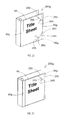
- FIG. 9 is a perspective view of another ring binder with a cover sheet in a closed position
- FIG. 10 is a perspective view of the binder of FIG. 9 as the cover sheet is moved between the closed position and an open position;
- FIG. 11 is a perspective view of the binder of FIG. 9 with the cover sheet in the open position;
- FIG. 12 is an end view of another label sleeve being inserted into a spine of another binder
- FIG. 13 is a perspective view of the binder of FIG. 12 including the label sleeve and spine label;
- FIG. 14 is a perspective view of another construction of a binder including a cover sheet
- FIG. 15 is a perspective view of another construction of a binder including a cover sheet
- FIG. 16 is a perspective view of yet another construction of a binder including a cover sheet
- FIG. 17 is a perspective view of still another construction of a binder including a cover sheet
- FIG. 18 is an enlarged perspective view of the binder of FIG. 17 taken along line 18 - 18 and showing one construction of a movable lip;
- FIG. 19 is an enlarged perspective view of the binder of FIG. 17 taken along line 18 - 18 and showing another construction of a movable lip;
- FIG. 20 is a perspective view of another construction of a binder including a cover sheet
- FIG. 21 is a perspective view of yet another construction of a binder including a cover sheet
- FIG. 22 is a perspective view of still another construction of a binder including a cover sheet
- FIG. 23 is a perspective view of another construction of a binder including a cover sheet
- FIG. 24 is a perspective view of yet another construction of a binder including a cover sheet
- FIG. 25 is a perspective view of still another construction of a binder including a cover sheet
- FIG. 26 is another perspective view of the binder of FIG. 25 ;
- FIG. 27 is a perspective view of another construction of a binder including a spine cover sheet
- FIG. 28 is a perspective view of another construction of a binder including a rear cover sheet
- FIG. 29 is a perspective view of another construction of a binder including an interior cover sheet
- FIG. 30 is a perspective view of another construction of a binder including a cover sheet
- FIG. 31 is a perspective view of yet another construction of a binder including a cover sheet
- FIG. 32 is a perspective view of still another construction of a binder including a pivotable cover sheet
- FIG. 33 is a perspective view of another construction of a binder including a cover sheet
- FIG. 34 is a perspective view of still another construction of a binder including a pivotable cover sheet
- FIG. 35 is a perspective view of another construction of a binder including a retainer
- FIG. 36 is an enlarged perspective view of the binder of FIG. 35 with the retainer partially removed.
- FIG. 37 is a section view of the binder of FIG. 35 taken along line 37 - 37 of FIG. 36 .
- the features of the present invention are also capable of being applied to other DSDs, such as folders, report covers, folios, and the like. Therefore, the present invention need not be limited to binder applications.
- FIG. 1 illustrates a molded plastic binder 10 that includes a front cover 15 , a rear cover 20 , and a spine 25 .
- the molded plastic binder 10 is formed from a substantially homogeneous plastic material in one or more manufacturing steps.
- the binder 10 of FIG. 1 also includes a ring mechanism 30 attached to the inner surface of one or more of the front cover 15 , the rear cover 20 , and the spine 25 .
- the ring mechanism 30 includes at least one ring 31 movable between an open position and a closed position. While the illustrated binder 10 includes the ring mechanism 30 , other binders suited to use with the present invention may not include the ring mechanism 30 .
- the front cover 15 and the rear cover 20 are substantially flat rectangular portions of the binder 10 that connect to the spine 25 along hinges 35 .
- the hinges 35 are generally thin flexible connections that allow the front cover 15 and the rear cover 20 to pivot relative to the spine 25 between an open position and a closed position.
- the front cover 15 defines a spine edge 40 adjacent the spine 25 and a lip edge 45 opposite and substantially parallel to the spine edge 40 .
- a top edge 50 extends between the lip edge 45 and the spine edge 40 along the top of the front cover 15
- a bottom edge 55 extends between the lip edge 45 and the spine edge 40 along the bottom of the front cover 15 .
- a translucent cover sheet 60 is attached to the front cover 15 .
- the cover sheet 60 is transparent to allow the uninhibited viewing of a title sheet 65 disposed within a title sheet space between the cover sheet 60 and the front cover 15 .
- the cover sheet 60 may include a pattern that enhances or otherwise affects the view of the title sheet 65 through the cover sheet 60 .
- the cover sheet 60 attaches to the front cover 15 or is formed as part of the front cover 15 such that it is substantially fixed at or adjacent to the spine edge 40 and is free along the remaining three cover edges 45 , 50 , 55 .
- the cover sheet 60 attaches to the front cover to define a hinge portion using any suitable means including but not limited to welding, adhesive, fasteners, and the like. In many constructions, a pocket is formed adjacent the hinge portion to receive a portion of the title sheet 65 . Other constructions may fix other edges of the cover sheet 60 such as the edge adjacent the top edge 50 , the bottom edge 55 , or the lip edge 45 .
- a cut-out portion 310 is provided to aid a user in grabbing or moving the cover sheet 60 .
- the cut-out portion 310 establishes an edge that a user can grab no matter the position of the cover sheet 60 .
- the cover sheet 60 is shown in an open position. As can be seen, the edges of the cover sheet 60 adjacent the lip edge 45 , the top edge 50 , and the bottom edge 55 are free to move relative to the front cover 15 . Once in the open position, the title sheet 65 can be inserted or removed as desired, as shown in FIG. 4 .
- the cover sheet 60 covers, protects, and retains the title sheet 65 in the desired position on the front cover 15 .
- the cover sheet 60 can be returned to the closed position as illustrated in FIG. 5 . Both the title sheet 65 and cover sheet 60 engage and are tucked under the lip edge 45 to retain them in the closed position during binder use. When the cover sheet 60 is in the closed position, the edges adjacent the top edge 50 and the bottom edge 55 are not secured to the front cover 15 . No additional securing device other than the lip edge 45 is needed to retain the cover sheet 60 in the closed position. In some constructions, static electricity and pressure forces (i.e., the low pressure between the cover sheet 60 and the front cover 15 and title sheet 65 created as they are separated) aid in holding the cover sheet 60 in the closed position.
- the front cover 15 includes a top lip 66 formed adjacent the top edge 50 and a bottom lip 67 formed adjacent the bottom edge 55 .
- the top lip 66 and the bottom lip 67 shown in FIG. 1 engage the title sheet 65 and inhibit its escape through the open top and bottom edges when the cover sheet 60 is in the closed position.
- the top lip 66 and bottom lip 67 may be continuous and extend completely across the top edge 50 and the bottom edge 55 or may extend along only a portion of the edges 50 , 55 .
- one or both of the lip edges may be made up of intermittent lips that extend across all or a portion of the top edge 50 and bottom edge 55 .
- the top lip 66 and the bottom lip 67 be formed as part of the front cover 15
- other constructions include separate pieces that attach to the front cover using any suitable attachment method.
- the lip edge 45 is shown in greater detail as including a top portion 70 and a panel portion 75 .
- the top portion 70 is spaced a distance from the panel portion 75 to define a gap 80 .
- the gap 80 is wide enough to receive at least the title sheet 65 and the cover sheet 60 .
- the lip edge 45 can be formed as part of the front cover 15 of the binder 10 or can be attached after the front cover 15 is formed. In constructions in which the lip edge 45 is connected to the front cover 15 , the lip edge 45 can be molded from a similar material as is used for the rest of the binder and the connection can be made using any suitable method (e.g., welding, adhesive, fasteners, and the like). While the lip edge 45 is shown as extending the entire height of the binder 10 , other constructions may employ a lip edge 45 that is shorter than the binder 10 if desired.
- the lip edge 45 extends the full length of the binder 10 and defines a depth 85 . While the actual depth 85 is not critical, it should be deep enough to retain the cover sheet 60 and title sheet 65 during normal binder use. As shown in FIG. 5 , the depth 85 extends from a contoured edge 90 to a lip edge bottom 95 (shown in FIG. 6 ). As such, the depth 85 varies along the length of the lip edge 45 .
- the contoured edge 90 includes an arcuate portion 100 near the center of the length. The arcuate portion 100 establishes an area having a small depth 85 .
- the arcuate portion 100 cooperates with the cut-out portion 60 a to allow the user to more easily insert and remove the cover sheet 60 for placement or removal of the title sheet 65 .
- Those of ordinary skill in the art will understand that other contouring can be used for the contoured edge 90 .
- the cover sheet 60 is pulled out from the lip edge 45 and opened to receive the title sheet 65 , as shown in FIG. 3 .
- the title sheet 65 is positioned as desired with at least a portion being positioned between the top portion 70 and the panel portion 75 of the lip edge 45 , as shown in FIG. 6 .
- the cover sheet 60 is then closed such that a portion of the cover sheet 60 also fits within the gap 80 adjacent the title sheet 65 .
- the panel portion 75 and the front cover 15 cooperate to define one surface, while the top portion 70 defines a second surface with the title sheet 65 sandwiched between the two surfaces.
- the front cover 15 alone defines the first surface such that the front cover 15 and the top portion 70 sandwich a portion of the title sheet 65 .
- the molded binder 10 employs a label sleeve 120 , as illustrated in FIG. 7 .
- the label sleeve 120 is a relatively stiff piece of plastic having a front portion 125 and a rear portion 130 , with at least a portion of the label sleeve 120 being translucent.
- the front portion 125 and rear portion 130 attach to each other along a hinge 135 that allows them to fold next to each other to form a substantially flat sheet.
- the spine label 115 disposed between the front and rear portions 125 , 130 is protected and stiffened to facilitate easy installation and removal.
- different colored label sleeves 120 are employed to further aid in identifying the contents of the binder 10 .
- FIG. 8 illustrates the label sleeve 120 being inserted into the spine cavity 136 of the molded binder 10 .
- the spine cavity 136 is formed by attaching a substantially rigid piece 137 to the spine 25 of the binder.
- the substantially rigid piece 137 is at least partially formed from a molded plastic portion. Attachment can be made using any suitable method including welding, adhesives, fasteners, and the like. In other constructions, the molded plastic piece 137 is formed as part of the binder 10 .
- the spine label 115 is positioned between the front portion 125 and rear portion 130 of the label sleeve 120 .
- the label sleeve 120 includes tabs 140 that extend above cut-outs 142 in the spine 25 to facilitate the easy removal of the label sleeve 120 .
- Tabs 140 can be located on both ends or only one end as may be required by the particular binder.
- a vinyl-covered binder 10 a incorporating a cover sheet 60 a is illustrated.
- the vinyl-covered binder 10 a is similar to the molded binder 10 in many respects but is manufactured differently.
- Vinyl-covered binders 10 a are generally manufactured by surrounding a relatively stiff material (e.g., cardboard, particle board, wood, plastic and the like) with vinyl or another plastic material.
- the binder structure is non-homogeneous.
- the vinyl-covered binder 10 a includes a front cover 15 a , a rear cover 20 a , and a spine portion 25 a .
- a ring mechanism 30 a may be employed to capture paper inserted in the binder 10 a .
- the ring mechanism 30 a if used, attaches to one or more of the front cover 15 a , the rear cover 20 a , or the binder spine 25 a.
- the front cover 15 a of the vinyl-covered binder 10 a defines a spine edge 40 a , a top edge 50 a , a bottom edge 55 a , and a lip edge 45 a .
- the cover sheet 60 a attaches to the binder 10 a adjacent the spine edge 40 a .
- the cover sheet 60 a can be formed as part of the vinyl cover, or can be attached separately using any suitable attachment method including, but not limited to adhesives, welding, fasteners, and the like. For example, one construction attaches the cover sheet 60 a to the vinyl cover in two locations. First, the cover sheet 60 a is inserted into a pocket such that it is positioned at least partially beneath the vinyl.
- the edge of the cover sheet 60 a is welded to the vinyl adjacent the edge of the cover sheet.
- a second weld line is placed along the junction where the cover sheet 60 a extends out from beneath the vinyl. In other constructions, only one of these weld locations is used. In still other constructions a jacket at least partially wraps around the binder cover and serves as an attachment point for the cover sheet 60 a . Any of the foregoing attachment methods will also work well with these constructions.
- the spine edge 40 a With the spine edge 40 a attached, the three edges of the cover sheet 60 a adjacent the top edge 50 a , the bottom edge 55 a , and the lip edge 45 a of the front cover 15 a remain free to move. This allows the cover sheet 60 a to move between a closed position and an open position as illustrated in FIGS. 9-11 . When in the closed position, the edge of the cover sheet 60 a opposite the spine edge 40 a engages a lip in the form of a pocket 105 that holds the cover sheet 60 a in the closed position.
- a sheet of plastic 110 attaches to the front cover 15 a to form the pocket 105 .
- the attachment can be made in any suitable manner including, but not limited to welding, adhesives, fasteners, and the like.
- the pocket 105 is able to receive a portion of the title sheet 65 a as well as a portion of the cover sheet 60 a and retain them in the closed position.
- a slit in the vinyl cover provides an opening that receives a portion of the title sheet 65 a and the cover sheet 60 a to hold them in the closed position.
- FIGS. 12 and 13 another label sleeve 120 a (with inserted label) is shown being inserted into a spine cavity in a vinyl-covered binder 10 a .
- the vinyl cover, or an additional piece of vinyl secured over the vinyl cover 145 defines a spine pocket 150 .
- the label sleeve 120 a is inserted into the spine pocket 150 from either the top opening or the bottom opening.
- the label sleeve 120 a can be pushed flat against the spine 25 a to aid in its insertion into the spine pocket 150 .
- the label sleeve 120 a illustrated in FIGS. 12-13 does not include tabs. However, other constructions of the label sleeve 120 a may include tabs if desired.
- the label sleeves 120 , 120 a are clear.
- other constructions include colored label sleeves.
- the colored label sleeves can be used to color code the binders and make it easier to pick a desired binder from a shelf based on the label sleeve color.
- label sleeves of different lengths or widths can be employed to accommodate different applications if desired.
- the label sleeves 120 , 120 a make it much easier to insert and remove spine labels 115 .
- the stiffness of the label sleeves 120 , 120 a provide the additional support needed to insert the long, narrow spine labels 115 .
- spine treatments could be used to retain a label 115 .
- the tuckable cover sheet configuration similar to the one shown and described as being used on the front covers 15 , 15 a could be used on the spines 25 , 25 a.
- FIGS. 14-34 illustrate a few of these possible constructions.
- FIGS. 14-34 illustrate a variety of different DSDs in the form of binders 200 .
- the binders 200 illustrated in FIGS. 14-34 could be constructed as molded binders, vinyl-covered binders, or any other type of binders known in the binder art. As one of ordinary skill will realize, the actual construction of the binder is not critical to the function of the invention.
- a binder 200 a is illustrated as including a spine-side pocket 205 and an edge pocket 210 .
- the spine-side pocket 205 and the edge pocket 210 extend the full vertical height of the binder 200 a and define lip edges 45 a sized to receive the title sheet 65 and a loose cover sheet 215 .
- the spine-side pocket 205 and the edge pocket 210 attach to the binder 200 a using any suitable means. For example, in one construction, three edges of each pocket 205 , 210 are welded to the cover of the binder 200 a . In another construction, the pockets 205 , 210 slide over the binder cover and are welded on the inside portion of the cover.
- the binder 200 a includes a top lip 66 and/or a bottom lip 67 (shown in FIG. 1 ) that hold the title sheet 65 and inhibit movement vertically.
- the pockets 205 , 210 are formed to perform this function and inhibit movement of the title sheet 65 and the cover sheet 215 in the vertical direction.
- the user To insert the title sheet 65 , the user first tucks one of the vertical edges into the spine-side pocket 205 or the edge pocket 210 and then tucks the opposite edge into the remaining pocket 205 , 210 .
- the translucent cover sheet 215 is inserted in a similar manner.
- the pockets 205 , 210 are sized and positioned to maintain the title sheet 65 and the cover sheet 215 in position during use of the binder.
- FIG. 15 shows the binder 200 a of FIG. 14 with the title sheet 65 and the cover sheet 215 in their tucked positions. While the construction of FIG. 15 illustrates the spine-side pocket 205 and the edge pocket 210 as being translucent, other constructions incorporate opaque pockets 205 , 210 .
- FIG. 16 illustrates a binder 200 b similar to that of FIGS. 1-9 with the exception that the cover sheet is defined by multiple separate cover sheet segments 220 a , 220 b , 220 c .
- FIG. 16 illustrates three segments 220 a , 220 b , 220 c with other constructions using two segments and still others using four or more segments.
- Each of the cover sheet segments 220 a , 220 b , 220 c is attached to the binder in a manner similar to that described with regard to the cover sheets 60 of FIGS. 1-9 .
- each cover sheet segment 220 a , 220 b , 220 c tucks beneath a lip edge 45 b to secure the cover sheet segment 220 a , 220 b , 220 c in place.
- multiple lip edges are provided for the multiple cover sheet segments.
- three lip edges could be provided to capture the three cover sheet segments illustrated in FIG. 16 .
- the three lip edges could be separated to define three separate pockets.
- cover sheet segments 220 a , 220 b , 220 c allow for the use of multiple colors, patterns, or textures if desired.
- multiple title sheet segments can be positioned under the individual cover sheet segments 220 a , 220 b , 220 c if desired.
- FIGS. 17-19 illustrate yet another construction of a binder 200 c in which a lip edge 225 is movably attached to the binder 200 c .
- the binder includes a translucent cover sheet 60 c that is attached to the binder 200 c along a spine edge 40 c in a manner that has been described. The remaining three edges remain free. The lip edge opposite the spine edge 40 c , tucks under the movable lip edge 225 .
- FIG. 18 shows one construction of the binder 200 c of FIG. 17 in which the movable lip edge 225 translates in a plane substantially parallel to the binder cover.
- the lip edge 225 a pivots about an axis B-B that is parallel to the binder cover.
- the movable lip edge 225 allows for the use of stiffer or thicker materials to make up the cover sheet 60 c or the title sheet 65 .
- the stiffer materials are not easily bent, thereby making them difficult to tuck.
- the cover sheet 60 c can be positioned as desired with the lip edge 225 in an open position. The lip edge 225 is then moved to a closed position to retain the title sheet 65 and the cover sheet 60 c.
- the binder 200 d includes a resilient member 230 such as a bungee or a rubber band that can be positioned to retain the cover sheet 60 d and the title sheet 65 in a desired position.
- the resilient member 230 attaches to the inner surface of the binder 200 d and can be positioned as illustrated in FIG. 20 .
- the cover sheet 60 d attaches to the binder 200 d as has been previously described, with the resilient member acting to restrain the free edge of the cover sheet 60 d opposite a binder spine edge 40 d .
- the resilient member can attach to any surface of the binder desired with the inner surface generally being the most convenient.
- FIG. 21 illustrates another construction of a binder 200 e having a cover sheet 60 e .
- the cover sheet 60 e attaches to the binder 200 e along a spine edge 40 e in much the same way as was described with regard to FIGS. 1-9 .
- the binder 200 e of FIG. 21 is similar to either of the binders 10 , 10 a described with reference to FIGS. 1-9 with the exception that no lip edge is provided.
- the binder 200 e of FIG. 21 includes an adhesive strip 235 positioned along the edge opposite the spine 40 e . The adhesive strip 235 engages and holds the cover sheet 60 e in the closed position.
- a permanent adhesive could be used
- preferred constructions include a reusable adhesive that allows for the multiple openings and closings of the cover sheet 60 e .
- adhesive as used within this application should be read broadly to include other fastening means such as, but not limited to, Velcro, snaps, hooks, buttons, and the like.
- FIG. 22 another binder 200 f including a movable cover sheet 60 f is illustrated.
- the translucent cover sheet 60 f is attached to the binder along two intersecting attachment edges 240 .
- the cover sheet 60 f is attached adjacent a spine edge 40 f , and a bottom edge 55 f of the binder 200 f to define a pocket 245 for receiving the title sheet 65 .
- the corner opposite the corner defined by the intersection of the attached edges 40 f , 55 f (the free corner) tucks beneath a lip to restrain the loose corner of the cover sheet 60 f .
- an adhesive portion is positioned adjacent the free corner to hold the corner of the cover sheet 60 f in place.
- a binder 200 g is illustrated as including a cover sheet 60 g attached to the binder 200 g along a spine edge 40 g in much the same manner as was described with regard to FIGS. 1-9 .
- the binder 200 g includes two corner pockets 245 that engage the corner of the title sheet 65 and the cover sheet 60 g to hold them in position. Attaching two edges 250 of a triangular piece 255 to the binder 200 g forms each pocket 245 .
- the corner pockets 245 slide over the corner of the binder 200 g and are welded to the inside portion of the cover to attach the pockets 245 to the binder 200 g.
- a single corner pocket 245 is used.
- the single pocket 245 can be positioned adjacent the top corner as illustrated, or alternatively, the corner pocket 245 can be positioned adjacent the bottom corner.
- FIGS. 25 and 26 illustrate yet another construction of a binder 200 h in which the cover sheet 60 h attaches to a cover 15 h of the binder 200 h adjacent a spine edge 40 h as has been previously described.
- the cover sheet 60 h wraps around the cover 15 h of the binder 200 h and tucks into a lip edge 45 h defined on the inner surface of the binder 200 h .
- the lip edge 45 h in the construction of FIG. 26 , includes a pocket 210 h having three edges welded to the binder 200 h and a fourth edge open to receive the cover sheet 60 h .
- the lip edge 45 h is formed as part of the binder 200 h rather than being a separate piece that attaches to the binder 200 h.
- FIG. 27 illustrates a binder 200 k that includes a tuckable cover sheet 260 positioned to hold a spine title page 265 .
- the tuckable sheet 260 attaches to the spine 25 k or to one of the binder covers 15 k , 20 k , adjacent one of the long edges of the spine 25 k .
- the opposite long edge includes a spine lip 270 that is similar to the lip edge 45 described herein.
- the spine lip 270 engages the free edge of the spine cover sheet 260 along with one edge of the spine title page 265 to restrain the two in the desired position.
- FIGS. 28 and 29 illustrate two examples of this.
- FIG. 28 illustrates a cover sheet 60 m positioned on a rear cover 20 m of a binder 200 m
- FIG. 29 illustrates a cover sheet 60 n positioned on an inside surface 275 of a binder 200 n front cover 15 n .
- the invention should not be limited to applications that include the front cover of the binder alone.
- FIG. 30 another binder 200 p is illustrated as including a cover sheet 60 p attached to the binder adjacent a top edge 50 p rather than a spine edge 40 p .
- the remaining three edges of the cover sheet 60 p remain free to move.
- a lip edge 45 p is positioned adjacent a bottom edge 55 p of the binder 200 p to engage the free edge of the cover sheet 60 p and hold the title sheet 65 and the cover sheet 60 p in place.
- the lip edge 45 p is similar to the lip edges already described.
- a cover sheet can be attached to a binder adjacent any edge of the binder.
- any of the remaining free edges of the cover sheet can engage a lip edge and hold the cover sheet as desired, with the opposite edge being preferred.
- the invention should not be limited to the orientations described herein.
- FIG. 31 illustrates another construction of a binder 200 r that includes a cover sheet 60 r that functions to cover a spine title page 265 r as well as a title sheet 65 r .
- the cover sheet 60 r attaches to the binder 200 r adjacent a rear vertical edge 275 of the binder 200 r and wraps around the front of the binder 200 r where a free end 280 engages a lip edge 45 r similar to those already described.
- the cover sheet 60 r can be attached to the binder 200 r on the spine side of the vertical edge 275 or on the rear cover side of the edge 275 as desired.
- a top edge lip and/or a bottom edge lip are provided on one or both of the spine and the front cover to inhibit undesirable vertical movement of the spine title page 265 r and the title sheet 65 r.
- top edge lip and a bottom edge lip could be applied to any construction of the binder to inhibit undesirable vertical movement of the spine title page or the title page if desired.
- the binder 200 r may also include a strip of adhesive 235 r adjacent the front vertical edge of the spine. The adhesive engages the cover sheet 60 r , thereby allowing the cover sheet 60 r to tightly cover the spine without slipping and disengaging from the lip edge 45 r.
- FIG. 32 illustrates another construction of a binder 200 s that includes a cover sheet 60 s .
- a pin 285 attaches the cover sheet 60 s to the front of the binder 200 s so that the cover sheet 60 s is pivotable about an axis.
- the cover sheet 60 s covers a title sheet 65 that is positioned on a binder cover 15 s .
- a lip edge 45 s extends around the perimeter of the binder cover 15 s in a position that facilitates the engagement of the edges of the cover sheet 60 s with the lip edges 45 s . In other constructions, only portions of the perimeter include lip edges 45 s.
- one or more corner pockets 245 s is used to hold the cover sheet 60 s in position.
- FIG. 34 illustrates a construction that includes three corner pockets 245 s . Each corner pocket 245 s attaches to the binder and functions in a manner similar to that already described.
- FIG. 33 illustrates another construction of a binder 200 t in which a cover sheet 215 t is not permanently attached to the binder 200 t .
- the cover sheet 215 t engages four corner pockets 245 t to cover a title sheet 65 positioned on a binder cover 15 t .
- three corner pockets 245 t , or even two corner pockets 245 t are used to hold the cover sheet 215 t .
- a lip edge in combination with one or more corner pockets 245 t holds the cover sheet 215 t in place.
- the hinder 200 u includes a cover that defines a front panel 15 u , a rear panel 20 u , and a spine 25 u .
- the binder 200 u also includes a retainer 290 that attaches to at least one of the front panel 15 u , the rear panel 20 u , and the spine 25 u to define a pocket 295 .
- the retainer 290 attaches to the spine 25 u .
- retainers 290 could be made to attach to any surface of the binder 200 u.
- the binder 200 u includes a plurality of binder attachment members in the form slots 300
- the retainer 290 includes a plurality of retainer attachment members in the form of tabs or hooks 305 .
- the hooks 305 align with and engage the slots 300 to define snap-fits and allow for the removable attachment of the retainer 290 to the spine 25 u.
- the pocket 295 is sized to receive a spine label 115 disposed in a label sleeve 120 similar to those illustrated in FIGS. 10 and 11 .
- the pocket 295 can be sized to hold other items.
- one construction includes a retainer that cooperates with the cover to define a pocket sized to retain a plurality of business cards. It should be clear that the pocket 295 can be sized to hold a variety of items. As such, the pocket 295 should not be limited to the few examples discussed.
Abstract
Description
Claims (20)
Priority Applications (1)
| Application Number | Priority Date | Filing Date | Title |
|---|---|---|---|
| US11/550,544 US7762589B2 (en) | 2004-01-30 | 2006-10-18 | Spine label insert for a document storage device |
Applications Claiming Priority (2)
| Application Number | Priority Date | Filing Date | Title |
|---|---|---|---|
| US10/768,850 US7320554B2 (en) | 2004-01-30 | 2004-01-30 | Tuckable cover for a document storage device |
| US11/550,544 US7762589B2 (en) | 2004-01-30 | 2006-10-18 | Spine label insert for a document storage device |
Related Parent Applications (1)
| Application Number | Title | Priority Date | Filing Date |
|---|---|---|---|
| US10/768,850 Division US7320554B2 (en) | 2004-01-30 | 2004-01-30 | Tuckable cover for a document storage device |
Publications (2)
| Publication Number | Publication Date |
|---|---|
| US20070086846A1 US20070086846A1 (en) | 2007-04-19 |
| US7762589B2 true US7762589B2 (en) | 2010-07-27 |
Family
ID=34826543
Family Applications (2)
| Application Number | Title | Priority Date | Filing Date |
|---|---|---|---|
| US10/768,850 Active 2025-05-01 US7320554B2 (en) | 2004-01-30 | 2004-01-30 | Tuckable cover for a document storage device |
| US11/550,544 Active 2025-05-17 US7762589B2 (en) | 2004-01-30 | 2006-10-18 | Spine label insert for a document storage device |
Family Applications Before (1)
| Application Number | Title | Priority Date | Filing Date |
|---|---|---|---|
| US10/768,850 Active 2025-05-01 US7320554B2 (en) | 2004-01-30 | 2004-01-30 | Tuckable cover for a document storage device |
Country Status (3)
| Country | Link |
|---|---|
| US (2) | US7320554B2 (en) |
| AU (1) | AU2004202154A1 (en) |
| CA (1) | CA2457235A1 (en) |
Cited By (3)
| Publication number | Priority date | Publication date | Assignee | Title |
|---|---|---|---|---|
| US20090314049A1 (en) * | 2006-07-24 | 2009-12-24 | Masaharu Ueda | Method for producing pearlitic rail excellent in wear resistance and ductility |
| USD667496S1 (en) | 2011-08-02 | 2012-09-18 | Avery Dennison Corporation | Spine region of a binder |
| US9327543B2 (en) | 2012-11-08 | 2016-05-03 | Ccl Label, Inc. | Binder |
Families Citing this family (16)
| Publication number | Priority date | Publication date | Assignee | Title |
|---|---|---|---|---|
| US7730593B1 (en) * | 2004-09-28 | 2010-06-08 | Juilly Brett A | Binder clip with label holder |
| US20110175343A1 (en) * | 2005-01-31 | 2011-07-21 | Pipe Maintenance, Inc. | Identification system for drill pipes and the like |
| US7717639B2 (en) * | 2006-10-11 | 2010-05-18 | Staples The Office Superstore, Llc | Binder |
| WO2008140318A1 (en) * | 2007-04-23 | 2008-11-20 | Roger Apelseth | Device and structure of a binder for inserting sheets |
| USD656188S1 (en) | 2008-07-07 | 2012-03-20 | Staples The Office Superstore, Llc | Binder |
| US20120180348A1 (en) * | 2011-01-14 | 2012-07-19 | Forever Cards Llc | Reusable greeting card and method |
| US20150021899A1 (en) | 2011-02-04 | 2015-01-22 | Rita Coore-Widener | Mirrored practice notebook |
| US9421811B2 (en) * | 2011-05-31 | 2016-08-23 | Hewlett-Packard Development Company, L.P. | Media binder |
| WO2012166128A1 (en) | 2011-05-31 | 2012-12-06 | Hewlett-Packard Development Company, Lp | Arrangements and assembly methods for a media binder and its components |
| US9994064B2 (en) | 2011-05-31 | 2018-06-12 | Hewlett-Packard Development Company, L.P. | Media binder |
| US20140311097A1 (en) * | 2013-02-21 | 2014-10-23 | Nicolas J. Etienne | Device for covering a door to provide for smoke and odor insulation and method for using and packaging same |
| US10239665B2 (en) * | 2013-05-31 | 2019-03-26 | Donn Molineux | Sanitizing pouch for electronics |
| USD882682S1 (en) * | 2014-08-29 | 2020-04-28 | Ideastream Consumer Products, Llc | Folder |
| USD849837S1 (en) * | 2017-10-04 | 2019-05-28 | Lsc Communications Us, Llc | Binder |
| CN109605976B (en) * | 2018-10-30 | 2021-02-19 | 西安科技大学 | Portable important data storage device for financial management |
| US11682316B2 (en) * | 2019-10-31 | 2023-06-20 | Worklife Brands Llc | Notebook with configurable note-taking guides and organizational features |
Citations (258)
| Publication number | Priority date | Publication date | Assignee | Title |
|---|---|---|---|---|
| US134249A (en) | 1872-12-24 | Improvement in book-covers | ||
| US170042A (en) | 1875-11-16 | Improvement in photograph-albums | ||
| US384697A (en) | 1888-06-19 | Thomas kelly | ||
| US478390A (en) | 1892-07-05 | William bergner | ||
| US498761A (en) | 1893-06-06 | Picture-holder | ||
| US720324A (en) | 1902-03-24 | 1903-02-10 | Alvah Bushnell Jr | Card-holder for envelops or wallets. |
| US757596A (en) | 1903-07-06 | 1904-04-19 | Alvah Bushnell Jr | Envelop or expanding wallet. |
| US868998A (en) | 1907-01-24 | 1907-10-22 | Samuel R Lang | Card holding or exhibiting device. |
| US1023834A (en) | 1911-03-03 | 1912-04-23 | John G Gareis | Bookbinding. |
| US1029280A (en) | 1911-01-23 | 1912-06-11 | Eli Davidson | Cover for magazines, pamphlets, sheet-music, and the like. |
| US1065414A (en) | 1910-10-05 | 1913-06-24 | Yawman & Erbe Mfg Co | Card or label holder. |
| US1194401A (en) | 1916-08-15 | Laweence a | ||
| US1330894A (en) | 1919-04-19 | 1920-02-17 | Elvay J Muffley | Visible-front magazine-holder |
| US1381674A (en) | 1921-06-14 | Film-mounting | ||
| US1435762A (en) | 1922-05-11 | 1922-11-14 | Tomsich Jakob | Picture frame |
| US1634064A (en) | 1926-03-20 | 1927-06-28 | Gaw O Hara Envelope Company | File wallet |
| US1673144A (en) | 1927-02-09 | 1928-06-12 | George Margaret E Barclay | Gift-presenting casing |
| US1677277A (en) | 1925-11-24 | 1928-07-17 | Max W Federbush | Removable window tag for binders |
| US1696629A (en) | 1928-04-16 | 1928-12-25 | Fenno Grace Lee | Book-cover file |
| US1723096A (en) | 1926-09-27 | 1929-08-06 | Clyde A Taylor | Manifold record holder |
| US1832715A (en) | 1930-08-05 | 1931-11-17 | London David | Garment bag |
| GB363876A (en) | 1931-02-04 | 1931-12-31 | William Joseph Evershed | Improvements in or relating to accounts books, ledgers and the like |
| US1865741A (en) | 1930-03-19 | 1932-07-05 | Rose E Carney | Binder and indicating device therefor |
| US1965679A (en) | 1932-06-22 | 1934-07-10 | Welliver | Detachable cover for paper bound books |
| US1975559A (en) | 1934-10-02 | smith | ||
| US2088953A (en) | 1935-12-30 | 1937-08-03 | Greer Elmer | Combined scholar's companion and loose leaf notebook |
| US2088672A (en) | 1936-09-24 | 1937-08-03 | Steinthal Augustus | Combined book cover and display mounting |
| US2150474A (en) | 1937-03-22 | 1939-03-14 | Williams Willis Park | Card holder for loose leaf binders |
| US2239145A (en) | 1939-06-26 | 1941-04-22 | Libbey Owens Ford Glass Co | Sample display book |
| US2304980A (en) | 1940-08-02 | 1942-12-15 | Gen Motors Corp | Method of making binders |
| US2390958A (en) | 1944-09-11 | 1945-12-11 | Perlin Samuel | Portfolio |
| US2422235A (en) | 1945-05-01 | 1947-06-17 | Arch C Greene | Book cover and case |
| US2477840A (en) | 1946-12-20 | 1949-08-02 | Andrew B Vasilas | Compact composite wallet |
| US2523129A (en) | 1947-02-25 | 1950-09-19 | Maier Betty | Combination book cover and handbag or wallet |
| US2532132A (en) | 1946-10-10 | 1950-11-28 | Paul R Vogel | Cardholder |
| US2544566A (en) | 1946-06-28 | 1951-03-06 | Joseph K Rose | Album |
| US2568178A (en) | 1949-01-18 | 1951-09-18 | Widder & Co J | Adjustable photograph mount |
| US2596131A (en) | 1947-08-08 | 1952-05-13 | Thomas | Combination bookholder and pocket construction |
| US2598755A (en) | 1949-04-20 | 1952-06-03 | Thomas H Birch | Display device |
| US2616431A (en) | 1952-11-04 | Display album | ||
| US2639168A (en) | 1950-09-19 | 1953-05-19 | Dayton Embossed Products Corp | Cover construction |
| US2639254A (en) | 1951-02-27 | 1953-05-19 | Eastman Kodak Co | Method of mounting 35-millimeter slides to prevent film buckle during projection |
| US2701426A (en) | 1953-08-18 | 1955-02-08 | Vlock Mark | Mount for X-ray films or radiographs |
| US2704546A (en) | 1955-03-22 | Ring binders | ||
| US2716985A (en) | 1955-02-24 | 1955-09-06 | Major Leather Goods Mfg Co | Combination loose leaf notebook and portable desk |
| US2742070A (en) | 1954-05-03 | 1956-04-17 | Jones Willard Winfred | Bible and sunday school data holder |
| US2755837A (en) | 1954-04-12 | 1956-07-24 | Henry E Kosek | Brief cases |
| US2801115A (en) | 1957-07-30 | Display panels for catalog binders and the like | ||
| US2828975A (en) | 1957-04-15 | 1958-04-01 | Wright Charles Buford | Pocket secretary |
| US2842882A (en) | 1954-08-27 | 1958-07-15 | Greene Nathan | Photographic mount for X-ray film |
| US2850294A (en) | 1958-09-02 | Picture album | ||
| US2852275A (en) | 1956-04-25 | 1958-09-16 | Wire O Corp | Contents indicator for binder covers |
| US2935807A (en) | 1957-09-03 | 1960-05-10 | Gibson Art Company | Display mount sheet for greeting cards |
| US3092400A (en) | 1959-11-27 | 1963-06-04 | William Jamieson | Loose-leaf binder |
| US3133750A (en) | 1961-09-29 | 1964-05-19 | Elizabeth B Gerald | Book cover |
| US3175847A (en) | 1963-03-06 | 1965-03-30 | Meredith Publishing Company | Plastic spine construction for ring binders |
| US3241863A (en) | 1962-10-19 | 1966-03-22 | George M Paddack | Book covers |
| US3252462A (en) | 1964-01-07 | 1966-05-24 | Demco Library Supplies Inc | Binder for magazines and the like |
| US3301621A (en) * | 1965-10-14 | 1967-01-31 | James H Stephenson | Transparent container for books, magazines and the like |
| US3431667A (en) | 1965-06-07 | 1969-03-11 | Richard M Woods | X-ray film mount |
| US3473246A (en) | 1967-05-03 | 1969-10-21 | Daniel M Parobek | Data recording device |
| US3485564A (en) | 1967-10-16 | 1969-12-23 | Holes Webway Co | Concealed binding and hinge means and cover |
| US3492743A (en) | 1967-11-06 | 1970-02-03 | Theodore G Schmidt | Educational art device |
| US3589049A (en) | 1969-07-08 | 1971-06-29 | Thelma L Cornelius | Picture frame box with record holder |
| US3663041A (en) | 1970-03-16 | 1972-05-16 | James C White | Binder |
| US3807883A (en) | 1970-03-17 | 1974-04-30 | Esselte Oebergs Ab | Label holding device for loose leaf binders |
| US3810324A (en) | 1972-10-27 | 1974-05-14 | R Hart | Mat for mounting prints |
| US3814527A (en) | 1972-06-08 | 1974-06-04 | M Lawes | Loose leaf binders |
| US3822495A (en) | 1972-11-28 | 1974-07-09 | Happy Shokai Co Ltd | Improved photograph mount |
| US3870223A (en) | 1974-01-07 | 1975-03-11 | Mead Corp | Double wing pocket portfolio and file folder |
| US3899082A (en) | 1973-09-04 | 1975-08-12 | Swingline Inc | Binder storage arrangement including removable flexible hangers |
| US3937493A (en) | 1974-09-30 | 1976-02-10 | The Smead Manufacturing Company | Color coded labels and file folders |
| US4001960A (en) | 1976-03-16 | 1977-01-11 | The Holson Company | Photo album cover with framed insert |
| US4164085A (en) | 1977-09-14 | 1979-08-14 | Hallmark Cards, Incorporated | Album having picture receiving frame assembly in cover |
| US4172332A (en) | 1977-10-03 | 1979-10-30 | The Holes-Webway Co. | Photograph album |
| US4175777A (en) | 1978-06-29 | 1979-11-27 | Horn Sherrye J | Book index and subject finder |
| US4215499A (en) | 1978-07-10 | 1980-08-05 | Wilson Harlan R | Collector's device |
| US4275517A (en) | 1977-03-18 | 1981-06-30 | Winthrop-Atkins Co., Inc. | Photograph mount |
| US4294469A (en) | 1979-08-06 | 1981-10-13 | Errichiello D | Book binders and books made with said binders |
| US4315642A (en) | 1979-08-06 | 1982-02-16 | Errichiello D | Integrally molded covers and spines for looseleaf books |
| US4332095A (en) | 1980-04-28 | 1982-06-01 | Goodren Products Corp. | Picture holder |
| US4336754A (en) | 1978-11-09 | 1982-06-29 | Identifax Nationwide Registry | Property identification system |
| US4378647A (en) | 1979-12-20 | 1983-04-05 | Vincenzo Stancato | Photographic album and method of fabrication of same |
| US4420112A (en) | 1979-07-20 | 1983-12-13 | Cline Robert C | Portfolio construction |
| USD272161S (en) | 1981-10-13 | 1984-01-10 | Wilson Jones Company | Divider sheet for a continuous form binder |
| US4531765A (en) | 1980-12-29 | 1985-07-30 | Polaroid Corporation, Patent Dept. | Color coded ID cards |
| US4566721A (en) | 1984-02-09 | 1986-01-28 | Buxton, Inc. | Folder with rewritable surface for checkbooks and the like |
| US4600346A (en) | 1985-11-22 | 1986-07-15 | Dennison National Company | Binder cover and method of manufacture thereof |
| US4605245A (en) | 1984-05-22 | 1986-08-12 | Weaver Leonard B | Self-adjusting book cover |
| US4629349A (en) | 1984-07-11 | 1986-12-16 | Dennison Manufacturing Company | Flexible transparent notebook and the like |
| US4630843A (en) | 1982-09-29 | 1986-12-23 | Harper House, Inc. | Binder |
| US4640413A (en) | 1985-05-31 | 1987-02-03 | Communications Transfer Corp. | Universal package for prerecorded computer disk and associated instructional material |
| USD289530S (en) | 1985-02-11 | 1987-04-28 | Arrington Galen C | Combined binder and radio |
| US4681472A (en) | 1986-05-02 | 1987-07-21 | Ruble Paul E | Self-loading binder |
| USD293335S (en) | 1984-06-08 | 1987-12-22 | Egly Robert A | Case for magnetic media, programs and the like |
| US4750884A (en) | 1985-08-09 | 1988-06-14 | American Trading And Production Corporation | Binder backing for notebooks |
| US4780975A (en) | 1987-02-26 | 1988-11-01 | Friedman Arthur S | Self mailer with easel |
| US4795194A (en) | 1987-05-20 | 1989-01-03 | Nancy Etheredge | Cover and jacket with pocket and method of manufacture thereof |
| US4809451A (en) | 1983-12-05 | 1989-03-07 | Canon Kabushiki Kaisha | Method for protecting a print |
| US4813803A (en) | 1987-10-05 | 1989-03-21 | Wilson Jones Company | Trigger mechanism for ring binder |
| US4828421A (en) | 1988-05-06 | 1989-05-09 | Arakaki Clifford S | Personalized loose-leaf album cover |
| US4830404A (en) | 1987-06-05 | 1989-05-16 | Lu Tsann T | Screen-like photo album |
| US4832369A (en) | 1987-10-30 | 1989-05-23 | Johnson Gary W | Wind resistant clipboard/padholder |
| US4831756A (en) | 1987-06-05 | 1989-05-23 | Huang Feng M | Album with replaceable front cover |
| US4835756A (en) | 1986-03-31 | 1989-05-30 | Hitachi, Ltd. | Optical memory apparatus using an optical disc having guide-grooves of V-shape and predetermined optical depth and access method therefor |
| US4838724A (en) | 1988-03-01 | 1989-06-13 | The Mead Corporation | Binder with pencil pocket |
| US4848798A (en) | 1988-09-23 | 1989-07-18 | The Mead Corporation | Perforated interior binder pocket |
| US4856817A (en) | 1988-08-12 | 1989-08-15 | The Mead Corporation | Easy grip binder |
| USD303548S (en) | 1986-04-21 | 1989-09-19 | The Mead Corporation | Ring binder |
| US4886299A (en) | 1989-01-03 | 1989-12-12 | Ducorday Gerard M | Book cover |
| US4890728A (en) | 1989-04-10 | 1990-01-02 | John Grimsley | Travel kit assembly |
| US4892333A (en) | 1987-06-04 | 1990-01-09 | Krulich Ronald F | Window pocket insertion device and method of use therefor |
| US4916838A (en) | 1988-06-17 | 1990-04-17 | The Holson Company | Photo holder for photo albums |
| US4934739A (en) | 1989-01-09 | 1990-06-19 | Albumx Corp. | Album page design |
| US4962951A (en) | 1988-04-21 | 1990-10-16 | Mechesney Veronica A | Book cover and note keeper system |
| USD313619S (en) | 1988-09-22 | 1991-01-08 | The Mead Corporation | Binder |
| US4991767A (en) | 1989-07-13 | 1991-02-12 | The Mead Corporation | Portfolio with photograph displaying cover |
| US4998840A (en) | 1990-06-12 | 1991-03-12 | Ruble Paul E | Method and tool for retrofitting an elongated label leader into the slot of an overlay binder |
| US5000319A (en) | 1989-06-02 | 1991-03-19 | Leon Mermelstein | Negative storage page with lock-in flaps |
| US5002311A (en) | 1989-09-29 | 1991-03-26 | Moore Business Forms | Parcel waybill |
| US5015011A (en) | 1990-07-23 | 1991-05-14 | The Mead Corporation | Binder with observation window |
| US5020828A (en) | 1989-05-24 | 1991-06-04 | The Mead Corporation | Heat-sealed die cut binder |
| US5030027A (en) | 1990-02-27 | 1991-07-09 | Scott Bachrach | Schedule and paperwork organizer |
| US5056825A (en) | 1990-04-09 | 1991-10-15 | Wallace Computer Services, Inc. | Referencing device |
| US5059052A (en) | 1989-09-18 | 1991-10-22 | T.H.E. Business Products Corporation | Portfolio system |
| US5067840A (en) | 1989-05-08 | 1991-11-26 | Acco World Corporation | Binder locking ring mechanism with configured trigger |
| US5074593A (en) | 1989-12-04 | 1991-12-24 | John Grosso | Insert holder with sealable opening |
| US5090732A (en) | 1990-05-14 | 1992-02-25 | Avant Incorporated | Inexpensive laminated universal sales presentation or security folder having many uses |
| US5100253A (en) | 1991-06-03 | 1992-03-31 | Acco World Corporation | Concealed rivet element and setting method for binder and the like |
| USD325928S (en) | 1984-12-05 | 1992-05-05 | American Trading And Production Corporation | Looseleaf binder |
| US5114009A (en) | 1991-04-26 | 1992-05-19 | Johnston Ronald C | Road-map holder and organizer |
| US5118137A (en) | 1991-02-21 | 1992-06-02 | American Trading And Production Corporation | Expansion pocket |
| US5160001A (en) | 1992-03-09 | 1992-11-03 | Incom America, Inc. A Corp. Of Texas | Computer carrying case |
| US5163768A (en) | 1992-01-07 | 1992-11-17 | Avery Dennison Corporation | Combined binder and suspended file assembly |
| US5199809A (en) | 1992-04-30 | 1993-04-06 | Semerjian Joseph K | Suspending clip for hanging binder |
| US5213368A (en) | 1992-04-27 | 1993-05-25 | The Mead Corporation | Loose-leaf binder having flexible spine |
| US5219437A (en) | 1992-01-21 | 1993-06-15 | The Mead Corporation | Fabric covered book cover |
| US5222825A (en) | 1992-03-18 | 1993-06-29 | The Mead Corporation | Round back binder |
| US5240340A (en) | 1991-11-22 | 1993-08-31 | Cullman Ventures, Inc. | Books and assemblies for books |
| USD340068S (en) | 1991-12-26 | 1993-10-05 | American Trading & Production Corporation | Combined memo holder and vertical file |
| US5261701A (en) | 1991-02-21 | 1993-11-16 | American Trading And Production Corporation | Expansion pocket |
| US5265359A (en) | 1992-02-13 | 1993-11-30 | Bennett Glazer | Display frame |
| USD343646S (en) | 1992-04-30 | 1994-01-25 | Acco Usa, Inc. | Trigger extension for a ring binder |
| US5286128A (en) | 1992-09-24 | 1994-02-15 | U.S. Ring Binder | Ring binder |
| US5299879A (en) | 1992-09-21 | 1994-04-05 | American Trading And Production Corporation | Index sheet assembly |
| US5330279A (en) | 1993-01-07 | 1994-07-19 | Ruble Paul E | Overlay binder including easy-release label leader |
| US5330281A (en) | 1993-07-16 | 1994-07-19 | Robert Kalan | Device for mounting photographs and the like |
| USD349514S (en) | 1991-10-11 | 1994-08-09 | Gotlund Sandra L | Pencil case |
| US5340155A (en) | 1992-11-20 | 1994-08-23 | Avery Dennison Corporation | Case-bound hot-melt binding system |
| USD350983S (en) | 1992-04-06 | 1994-09-27 | R. E. P. Industries, Inc. | Portable writing ledger |
| US5368333A (en) | 1994-01-31 | 1994-11-29 | Arroyo; Ralph | Loose leaf binder |
| US5383568A (en) | 1989-12-29 | 1995-01-24 | Avery Dennison Corporation | Method and article for packaging paper and the like |
| US5393154A (en) | 1992-10-27 | 1995-02-28 | Acco Usa, Inc. | Hook and binder arrangement |
| US5395137A (en) * | 1992-12-07 | 1995-03-07 | Kim; Hae-Woon | Color code label |
| USD356337S (en) | 1994-04-18 | 1995-03-14 | American Trading And Production Corporation | Horizontal and vertical organizer with insert |
| US5411293A (en) | 1994-06-07 | 1995-05-02 | American Trading And Production Corporation | Double cover ring binder |
| US5431449A (en) | 1993-04-02 | 1995-07-11 | Noritsu Koki Co., Ltd. | Film storing sheet |
| US5437514A (en) | 1994-11-18 | 1995-08-01 | The Chilcote Company | Photographic album leaf |
| US5441357A (en) | 1993-08-27 | 1995-08-15 | Avery Dennison Corporation | Case made ring binder and method of fabricating same |
| US5445417A (en) | 1993-07-12 | 1995-08-29 | Eskco, Inc. | Presentation folder and method of making |
| US5445251A (en) | 1993-08-02 | 1995-08-29 | American Trading & Production Corporation | Binder or portfolio |
| US5449202A (en) | 1994-06-24 | 1995-09-12 | Nalepka; Michael D. | Method and apparatus for color coded library and shelved media system |
| US5461810A (en) | 1994-05-31 | 1995-10-31 | Goserud; J. Thomas | Self-framing display holder for flat objects |
| USD365361S (en) | 1993-12-27 | 1995-12-19 | Smith Richard F | Molded album |
| US5490739A (en) | 1995-05-05 | 1996-02-13 | Olson; Kristin | Window display photo album |
| US5503487A (en) | 1994-09-09 | 1996-04-02 | Ong; Bon S. | Custom index tabs |
| US5509746A (en) | 1994-06-22 | 1996-04-23 | Ho; Cheng-Cheng | Loose-leaf picture album |
| US5562309A (en) | 1993-07-30 | 1996-10-08 | Waldorf Corporation | Print folder with pre-applied double stick tape |
| US5564623A (en) | 1993-06-11 | 1996-10-15 | American Trading And Production Corporation | Durable case formed from an expanded high-density polyethylene |
| US5569503A (en) | 1995-05-31 | 1996-10-29 | C. R. Gibson Company | Mounting substrate for display of items |
| US5584387A (en) | 1996-01-19 | 1996-12-17 | Grant; Richard B. | Combination book and package case assembly |
| US5605354A (en) | 1995-05-27 | 1997-02-25 | Kwon; Hyung-Seok | Album |
| US5607246A (en) | 1994-08-26 | 1997-03-04 | Avery Dennison Corporation | Ring binder |
| US5618061A (en) | 1995-09-21 | 1997-04-08 | American Trading And Production Corporation | Folder with slide-stiffener assembly |
| US5620207A (en) | 1992-04-21 | 1997-04-15 | Avery Dennison Corporation | Ring binder cover |
| US5642954A (en) | 1996-05-15 | 1997-07-01 | Avery Dennison Corporation | Space-saving collapsible ring binder |
| US5651628A (en) | 1993-07-30 | 1997-07-29 | Samsill Corporation | Loose-leaf binder and method and apparatus for manufacturing improved loose-leaf binders |
| US5660514A (en) | 1995-09-07 | 1997-08-26 | Specialty Loose Leaf, Inc. | Method of making pocket liner for covers of looseleaf binders or books |
| US5671950A (en) | 1996-09-26 | 1997-09-30 | Ampad Corporation | Fastenable binder with insert |
| US5674021A (en) | 1996-11-08 | 1997-10-07 | Hutnick; Maria | Cover for holding transcript and exhibit pages and method of making same |
| US5676482A (en) | 1996-06-21 | 1997-10-14 | Hawkins; Cynthia Sidwell | Machine-washable album with removably affixing means |
| US5683111A (en) | 1996-01-11 | 1997-11-04 | Image Bind, L.L.C. | Binder system and kit |
| US5711627A (en) * | 1996-05-08 | 1998-01-27 | Chapman; David R. | Flexible spine binder with window pocket and spine stiffener insert |
| US5720564A (en) | 1996-03-21 | 1998-02-24 | Winzen; Debra | Binder with label holder |
| US5762375A (en) | 1997-01-16 | 1998-06-09 | Dart Manufacturing Company | Inlaid portfolio and method of making same |
| US5826851A (en) | 1996-05-31 | 1998-10-27 | Arbisi; Dominic S. | Plastic mounting membrane using electrostatic attraction |
| US5836507A (en) | 1997-02-14 | 1998-11-17 | Mueller; David C. | Display folder |
| US5853259A (en) | 1997-12-02 | 1998-12-29 | Murray, Jr.; George E. | Binder labeling assembly |
| US5857797A (en) | 1996-12-17 | 1999-01-12 | H.C. Miller Company | Loose leaf binder including an exterior picture frame |
| USD405825S (en) | 1998-02-26 | 1999-02-16 | Avery Dennison Corporation | Embossed and decorated spine panel and cover for ring binder |
| US5876143A (en) | 1996-12-04 | 1999-03-02 | Ong; Bon S. | Document binder with cover pocket for custom title sheet |
| USD406602S (en) | 1998-02-26 | 1999-03-09 | Avery Dennison Corporation | Patterned embossed spine panel and cover for ring binder |
| USD406603S (en) | 1998-02-26 | 1999-03-09 | Avery Dennison Corporation | Linear embossed spine panel and cover for ring binder |
| US5882038A (en) | 1996-07-17 | 1999-03-16 | Ong; Bon S. | Custom presentation folder |
| USD409385S (en) | 1997-08-29 | 1999-05-11 | Acco Brands, Inc. | Thermo-form binder |
| US5911441A (en) | 1997-02-21 | 1999-06-15 | Avery Dennison Corporation | Zippered three-ring binder carrying case with additional external zippered cover for notepad |
| USD412530S (en) | 1997-08-29 | 1999-08-03 | Acco Brands, Inc. | Retractable, lay-flat handle for a binder |
| US5944352A (en) | 1998-02-20 | 1999-08-31 | Crouch; Jimmy | Notebook binder device with a central window |
| US5947524A (en) | 1995-11-08 | 1999-09-07 | Avery Dennison Corporation | Cover folder |
| USD413923S (en) | 1998-09-21 | 1999-09-14 | Acco Brands, Inc. | Binder |
| USD413924S (en) | 1997-08-28 | 1999-09-14 | Acco Brands, Inc. | Snap binder |
| USD414801S (en) | 1998-10-07 | 1999-10-05 | Avery Dennison Corporation | Curved configuration binder |
| USD417697S (en) | 1997-08-28 | 1999-12-14 | Acco Brands, Inc. | End portion of a hanging data binder |
| USD417890S (en) | 1998-10-02 | 1999-12-21 | Avery Dennison Corporation | Cover assembly of a binder with double layer transparent pockets |
| US6012866A (en) | 1997-02-11 | 2000-01-11 | Avery Dennison Corporation | Sheet protector |
| US6017164A (en) | 1998-09-15 | 2000-01-25 | Abbott; Marc Dean | Folio with three-part stiffener and viewing pockets |
| US6019540A (en) * | 1997-06-04 | 2000-02-01 | Duraweld Limited | Devices for inserting and removing labels |
| US6030140A (en) | 1998-10-07 | 2000-02-29 | Avery Dennison Corporation | Binder |
| US6030139A (en) | 1998-10-08 | 2000-02-29 | Avery Dennison Corporation | Flanged cover with prongs for a ring binder assembly |
| USD421460S (en) | 1998-10-02 | 2000-03-07 | Avery Dennison Corporation | Binder with double layer transparent pockets |
| US6032984A (en) | 1997-09-22 | 2000-03-07 | Visca Medical Filing Co., Ltd. | Mid-digit color coded filing system and folders |
| US6045161A (en) | 1998-04-07 | 2000-04-04 | Avery Dennison Corporation | Display sheet centering tab assembly |
| US6047990A (en) | 1996-10-18 | 2000-04-11 | Post-Fax Inc. | Report cover system with tuck closure |
| USD423044S (en) | 1998-11-05 | 2000-04-18 | Avery Dennison Corporation | Tab compatible divider label sheet |
| US6068423A (en) | 1994-12-01 | 2000-05-30 | Avery Dennison Corporation | Printable divider assembly having folded flap |
| US6086105A (en) | 1997-10-14 | 2000-07-11 | Learning Resources, Inc. | Book for packaging activity pieces in an activity kit |
| US6086106A (en) | 1998-09-18 | 2000-07-11 | Avery Dennison Corporation | Double vision cover and binder assembly |
| US6095564A (en) | 1999-06-24 | 2000-08-01 | Avery Dennison Corporation | Partitioned binder having a ring binder compartment and a storage compartment |
| US6109812A (en) | 1999-03-26 | 2000-08-29 | Acco Brands, Inc. | Binder with spine window and removable insert therein |
| US6117264A (en) | 1996-02-29 | 2000-09-12 | Brewster; Blair Meloy | Color coded warning label with removable coating |
| US6149205A (en) | 2000-03-24 | 2000-11-21 | Avery Dennison Corporation | Two layer mailer envelope for brochure |
| USD435269S (en) | 2000-03-27 | 2000-12-19 | Avery Dennison Corporation | Curvilinear molded plastic binder |
| US6186690B1 (en) | 1998-11-03 | 2001-02-13 | Napco, Inc. | Strap connection system |
| US6206602B1 (en) | 1999-07-27 | 2001-03-27 | Avery Dennison Corporation | “See-through” binder with printed frame cover |
| US6213670B1 (en) | 1999-07-26 | 2001-04-10 | Avery Dennison Corporation | Binders with a foldable pocket assembly |
| US6213669B1 (en) | 1999-06-18 | 2001-04-10 | Avery Dennison Corporation | Inflatable binder |
| US6227746B1 (en) | 1997-08-19 | 2001-05-08 | Acco Brands, Inc. | Hanging data binder |
| US6234701B1 (en) | 1998-10-07 | 2001-05-22 | Avery Dennison Corporation | Molded plastic binder |
| US6241414B1 (en) | 1999-07-26 | 2001-06-05 | Avery Dennison Corporation | Binders with flexible pockets |
| US6250834B1 (en) | 1999-06-16 | 2001-06-26 | Avery Dennison Corporation | Versatile binder assembly with an exterior pocket(s) |
| US6261021B1 (en) | 1999-11-16 | 2001-07-17 | Acco Brands, Inc. | Binder insert having a clip |
| US6276862B1 (en) | 1999-09-15 | 2001-08-21 | Acco Brands, Inc. | Binder mechanism |
| US6293722B1 (en) | 1999-09-15 | 2001-09-25 | Acco Brands, Inc. | Binder Mechanism |
| US6296727B1 (en) | 2000-03-17 | 2001-10-02 | Avery Dennison Corporation | Method for ultrasonically sealing a plastic film composed of polypropylene |
| US6305714B1 (en) | 1999-07-02 | 2001-10-23 | Acco Brands, Inc. | Folder with framed windows and method of manufacturing thereof |
| US6358587B1 (en) | 1999-03-11 | 2002-03-19 | Avery Dennison Corporation | Multiple material printable sheet with inset |
| US6361236B1 (en) | 1997-08-07 | 2002-03-26 | Avery Dennison Corporation | Paper storage item and method of making same |
| US6361639B1 (en) | 1999-05-12 | 2002-03-26 | Avery Dennison Corporation | Method of manufacturing an index divider sheet assembly |
| US6368005B1 (en) | 1996-12-17 | 2002-04-09 | H.C. Miller Company | Loose leaf binder including an exterior picture frame |
| US6367842B1 (en) | 1999-06-15 | 2002-04-09 | Avery Dennison Corporation | Binder with reclosable outer transparent window |
| US6375604B1 (en) | 1997-10-29 | 2002-04-23 | Avery Dennison Corporation | Method of forming a tabbed assembly |
| US6409409B2 (en) | 1998-12-15 | 2002-06-25 | Avery Dennison Corporation | Tabbed divider and pocket construction |
| US6450399B1 (en) | 2001-01-05 | 2002-09-17 | Avery Dennison Corporation | Printable triple-layer mailer assembly |
| US20020159816A1 (en) | 2001-04-25 | 2002-10-31 | Avery Dennison Corporation | Document protection and display assembly |
| US6478336B2 (en) | 2000-12-04 | 2002-11-12 | Lam H. Tran | Shallow box binder cover |
| US6481572B2 (en) | 2001-03-06 | 2002-11-19 | Avery Dennison Corporation | All in one multi-layer label and insert assembly |
| US20030044222A1 (en) | 2001-09-06 | 2003-03-06 | Avery Dennison Corporation | Conformable binders |
| US6550812B1 (en) | 2002-02-15 | 2003-04-22 | Avery Dennison Corporation | Magnetic write/erase binder |
| USD476682S1 (en) | 2001-11-09 | 2003-07-01 | Acco Brands, Inc. | Binder |
| USD478349S1 (en) | 2002-05-13 | 2003-08-12 | Avery Dennison Corporation | Belt binder |
| US6682247B1 (en) * | 2000-06-30 | 2004-01-27 | Avery Dennsion Corporation | Drawable and/or traceable carriers |
| US20040069841A1 (en) | 2002-10-10 | 2004-04-15 | Avery Dennison Corporation | Sleeve with corner tabs |
| US6761498B1 (en) * | 2003-04-02 | 2004-07-13 | Avery Dennison Corporation | Binder construction for easy insertion and removal of spine label |
| US20050046173A1 (en) | 2003-08-29 | 2005-03-03 | Hall Lindsay R. | Body with outer detachable pouch |
| US6902340B2 (en) * | 2003-04-02 | 2005-06-07 | Avery Dennison Corp. | Binder construction for easy insertion and removal of spine label |
| US20050226681A1 (en) | 2004-03-31 | 2005-10-13 | Adam Merzon | Binder |
| US7077596B1 (en) | 1999-11-17 | 2006-07-18 | Meadwestvaco Corporation | Notebook with two-way pocket |
| US20070086841A1 (en) | 2004-03-31 | 2007-04-19 | Adam Merzon | Title slide spine applicator |
Family Cites Families (4)
| Publication number | Priority date | Publication date | Assignee | Title |
|---|---|---|---|---|
| US5025581A (en) * | 1989-09-11 | 1991-06-25 | Polzin Ellen C | Display holder |
| CA2082251A1 (en) * | 1992-11-05 | 1994-05-06 | Peter L. Pacione | Two-piece presentation folder |
| SG46952A1 (en) * | 1995-10-13 | 1998-03-20 | Offshore Technology Dev Pte Lt | Self positioning fixation system |
| US5795089A (en) * | 1996-10-15 | 1998-08-18 | Ong; Bon S. | Transparency sheet protector |
-
2004
- 2004-01-30 US US10/768,850 patent/US7320554B2/en active Active
- 2004-02-06 CA CA002457235A patent/CA2457235A1/en not_active Abandoned
- 2004-05-19 AU AU2004202154A patent/AU2004202154A1/en not_active Abandoned
-
2006
- 2006-10-18 US US11/550,544 patent/US7762589B2/en active Active
Patent Citations (266)
| Publication number | Priority date | Publication date | Assignee | Title |
|---|---|---|---|---|
| US1975559A (en) | 1934-10-02 | smith | ||
| US170042A (en) | 1875-11-16 | Improvement in photograph-albums | ||
| US384697A (en) | 1888-06-19 | Thomas kelly | ||
| US478390A (en) | 1892-07-05 | William bergner | ||
| US498761A (en) | 1893-06-06 | Picture-holder | ||
| US1381674A (en) | 1921-06-14 | Film-mounting | ||
| US2850294A (en) | 1958-09-02 | Picture album | ||
| US2801115A (en) | 1957-07-30 | Display panels for catalog binders and the like | ||
| US134249A (en) | 1872-12-24 | Improvement in book-covers | ||
| US2704546A (en) | 1955-03-22 | Ring binders | ||
| US1194401A (en) | 1916-08-15 | Laweence a | ||
| US2616431A (en) | 1952-11-04 | Display album | ||
| US720324A (en) | 1902-03-24 | 1903-02-10 | Alvah Bushnell Jr | Card-holder for envelops or wallets. |
| US757596A (en) | 1903-07-06 | 1904-04-19 | Alvah Bushnell Jr | Envelop or expanding wallet. |
| US868998A (en) | 1907-01-24 | 1907-10-22 | Samuel R Lang | Card holding or exhibiting device. |
| US1065414A (en) | 1910-10-05 | 1913-06-24 | Yawman & Erbe Mfg Co | Card or label holder. |
| US1029280A (en) | 1911-01-23 | 1912-06-11 | Eli Davidson | Cover for magazines, pamphlets, sheet-music, and the like. |
| US1023834A (en) | 1911-03-03 | 1912-04-23 | John G Gareis | Bookbinding. |
| US1330894A (en) | 1919-04-19 | 1920-02-17 | Elvay J Muffley | Visible-front magazine-holder |
| US1435762A (en) | 1922-05-11 | 1922-11-14 | Tomsich Jakob | Picture frame |
| US1677277A (en) | 1925-11-24 | 1928-07-17 | Max W Federbush | Removable window tag for binders |
| US1634064A (en) | 1926-03-20 | 1927-06-28 | Gaw O Hara Envelope Company | File wallet |
| US1723096A (en) | 1926-09-27 | 1929-08-06 | Clyde A Taylor | Manifold record holder |
| US1673144A (en) | 1927-02-09 | 1928-06-12 | George Margaret E Barclay | Gift-presenting casing |
| US1696629A (en) | 1928-04-16 | 1928-12-25 | Fenno Grace Lee | Book-cover file |
| US1865741A (en) | 1930-03-19 | 1932-07-05 | Rose E Carney | Binder and indicating device therefor |
| US1832715A (en) | 1930-08-05 | 1931-11-17 | London David | Garment bag |
| GB363876A (en) | 1931-02-04 | 1931-12-31 | William Joseph Evershed | Improvements in or relating to accounts books, ledgers and the like |
| US1965679A (en) | 1932-06-22 | 1934-07-10 | Welliver | Detachable cover for paper bound books |
| US2088953A (en) | 1935-12-30 | 1937-08-03 | Greer Elmer | Combined scholar's companion and loose leaf notebook |
| US2088672A (en) | 1936-09-24 | 1937-08-03 | Steinthal Augustus | Combined book cover and display mounting |
| US2150474A (en) | 1937-03-22 | 1939-03-14 | Williams Willis Park | Card holder for loose leaf binders |
| US2239145A (en) | 1939-06-26 | 1941-04-22 | Libbey Owens Ford Glass Co | Sample display book |
| US2304980A (en) | 1940-08-02 | 1942-12-15 | Gen Motors Corp | Method of making binders |
| US2390958A (en) | 1944-09-11 | 1945-12-11 | Perlin Samuel | Portfolio |
| US2422235A (en) | 1945-05-01 | 1947-06-17 | Arch C Greene | Book cover and case |
| US2544566A (en) | 1946-06-28 | 1951-03-06 | Joseph K Rose | Album |
| US2532132A (en) | 1946-10-10 | 1950-11-28 | Paul R Vogel | Cardholder |
| US2477840A (en) | 1946-12-20 | 1949-08-02 | Andrew B Vasilas | Compact composite wallet |
| US2523129A (en) | 1947-02-25 | 1950-09-19 | Maier Betty | Combination book cover and handbag or wallet |
| US2596131A (en) | 1947-08-08 | 1952-05-13 | Thomas | Combination bookholder and pocket construction |
| US2568178A (en) | 1949-01-18 | 1951-09-18 | Widder & Co J | Adjustable photograph mount |
| US2598755A (en) | 1949-04-20 | 1952-06-03 | Thomas H Birch | Display device |
| US2639168A (en) | 1950-09-19 | 1953-05-19 | Dayton Embossed Products Corp | Cover construction |
| US2639254A (en) | 1951-02-27 | 1953-05-19 | Eastman Kodak Co | Method of mounting 35-millimeter slides to prevent film buckle during projection |
| US2701426A (en) | 1953-08-18 | 1955-02-08 | Vlock Mark | Mount for X-ray films or radiographs |
| US2755837A (en) | 1954-04-12 | 1956-07-24 | Henry E Kosek | Brief cases |
| US2742070A (en) | 1954-05-03 | 1956-04-17 | Jones Willard Winfred | Bible and sunday school data holder |
| US2842882A (en) | 1954-08-27 | 1958-07-15 | Greene Nathan | Photographic mount for X-ray film |
| US2716985A (en) | 1955-02-24 | 1955-09-06 | Major Leather Goods Mfg Co | Combination loose leaf notebook and portable desk |
| US2852275A (en) | 1956-04-25 | 1958-09-16 | Wire O Corp | Contents indicator for binder covers |
| US2828975A (en) | 1957-04-15 | 1958-04-01 | Wright Charles Buford | Pocket secretary |
| US2935807A (en) | 1957-09-03 | 1960-05-10 | Gibson Art Company | Display mount sheet for greeting cards |
| US3092400A (en) | 1959-11-27 | 1963-06-04 | William Jamieson | Loose-leaf binder |
| US3133750A (en) | 1961-09-29 | 1964-05-19 | Elizabeth B Gerald | Book cover |
| US3241863A (en) | 1962-10-19 | 1966-03-22 | George M Paddack | Book covers |
| US3175847A (en) | 1963-03-06 | 1965-03-30 | Meredith Publishing Company | Plastic spine construction for ring binders |
| US3252462A (en) | 1964-01-07 | 1966-05-24 | Demco Library Supplies Inc | Binder for magazines and the like |
| US3431667A (en) | 1965-06-07 | 1969-03-11 | Richard M Woods | X-ray film mount |
| US3301621A (en) * | 1965-10-14 | 1967-01-31 | James H Stephenson | Transparent container for books, magazines and the like |
| US3473246A (en) | 1967-05-03 | 1969-10-21 | Daniel M Parobek | Data recording device |
| US3485564A (en) | 1967-10-16 | 1969-12-23 | Holes Webway Co | Concealed binding and hinge means and cover |
| US3492743A (en) | 1967-11-06 | 1970-02-03 | Theodore G Schmidt | Educational art device |
| US3589049A (en) | 1969-07-08 | 1971-06-29 | Thelma L Cornelius | Picture frame box with record holder |
| US3663041A (en) | 1970-03-16 | 1972-05-16 | James C White | Binder |
| US3807883A (en) | 1970-03-17 | 1974-04-30 | Esselte Oebergs Ab | Label holding device for loose leaf binders |
| US3814527A (en) | 1972-06-08 | 1974-06-04 | M Lawes | Loose leaf binders |
| US3810324A (en) | 1972-10-27 | 1974-05-14 | R Hart | Mat for mounting prints |
| US3822495A (en) | 1972-11-28 | 1974-07-09 | Happy Shokai Co Ltd | Improved photograph mount |
| US3899082A (en) | 1973-09-04 | 1975-08-12 | Swingline Inc | Binder storage arrangement including removable flexible hangers |
| US3870223A (en) | 1974-01-07 | 1975-03-11 | Mead Corp | Double wing pocket portfolio and file folder |
| US3937493A (en) | 1974-09-30 | 1976-02-10 | The Smead Manufacturing Company | Color coded labels and file folders |
| US4001960A (en) | 1976-03-16 | 1977-01-11 | The Holson Company | Photo album cover with framed insert |
| US4275517A (en) | 1977-03-18 | 1981-06-30 | Winthrop-Atkins Co., Inc. | Photograph mount |
| US4164085A (en) | 1977-09-14 | 1979-08-14 | Hallmark Cards, Incorporated | Album having picture receiving frame assembly in cover |
| US4172332A (en) | 1977-10-03 | 1979-10-30 | The Holes-Webway Co. | Photograph album |
| US4175777A (en) | 1978-06-29 | 1979-11-27 | Horn Sherrye J | Book index and subject finder |
| US4215499A (en) | 1978-07-10 | 1980-08-05 | Wilson Harlan R | Collector's device |
| US4336754A (en) | 1978-11-09 | 1982-06-29 | Identifax Nationwide Registry | Property identification system |
| US4420112A (en) | 1979-07-20 | 1983-12-13 | Cline Robert C | Portfolio construction |
| US4294469A (en) | 1979-08-06 | 1981-10-13 | Errichiello D | Book binders and books made with said binders |
| US4315642A (en) | 1979-08-06 | 1982-02-16 | Errichiello D | Integrally molded covers and spines for looseleaf books |
| US4378647A (en) | 1979-12-20 | 1983-04-05 | Vincenzo Stancato | Photographic album and method of fabrication of same |
| US4332095A (en) | 1980-04-28 | 1982-06-01 | Goodren Products Corp. | Picture holder |
| US4531765A (en) | 1980-12-29 | 1985-07-30 | Polaroid Corporation, Patent Dept. | Color coded ID cards |
| USD272161S (en) | 1981-10-13 | 1984-01-10 | Wilson Jones Company | Divider sheet for a continuous form binder |
| US4630843A (en) | 1982-09-29 | 1986-12-23 | Harper House, Inc. | Binder |
| US4809451A (en) | 1983-12-05 | 1989-03-07 | Canon Kabushiki Kaisha | Method for protecting a print |
| US4566721A (en) | 1984-02-09 | 1986-01-28 | Buxton, Inc. | Folder with rewritable surface for checkbooks and the like |
| US4605245A (en) | 1984-05-22 | 1986-08-12 | Weaver Leonard B | Self-adjusting book cover |
| USD293335S (en) | 1984-06-08 | 1987-12-22 | Egly Robert A | Case for magnetic media, programs and the like |
| US4629349A (en) | 1984-07-11 | 1986-12-16 | Dennison Manufacturing Company | Flexible transparent notebook and the like |
| USD325928S (en) | 1984-12-05 | 1992-05-05 | American Trading And Production Corporation | Looseleaf binder |
| USD289530S (en) | 1985-02-11 | 1987-04-28 | Arrington Galen C | Combined binder and radio |
| US4640413A (en) | 1985-05-31 | 1987-02-03 | Communications Transfer Corp. | Universal package for prerecorded computer disk and associated instructional material |
| US4750884A (en) | 1985-08-09 | 1988-06-14 | American Trading And Production Corporation | Binder backing for notebooks |
| US4600346A (en) | 1985-11-22 | 1986-07-15 | Dennison National Company | Binder cover and method of manufacture thereof |
| US4835756A (en) | 1986-03-31 | 1989-05-30 | Hitachi, Ltd. | Optical memory apparatus using an optical disc having guide-grooves of V-shape and predetermined optical depth and access method therefor |
| USD303548S (en) | 1986-04-21 | 1989-09-19 | The Mead Corporation | Ring binder |
| US4681472A (en) | 1986-05-02 | 1987-07-21 | Ruble Paul E | Self-loading binder |
| US4780975A (en) | 1987-02-26 | 1988-11-01 | Friedman Arthur S | Self mailer with easel |
| US4795194A (en) | 1987-05-20 | 1989-01-03 | Nancy Etheredge | Cover and jacket with pocket and method of manufacture thereof |
| US4892333A (en) | 1987-06-04 | 1990-01-09 | Krulich Ronald F | Window pocket insertion device and method of use therefor |
| US4831756A (en) | 1987-06-05 | 1989-05-23 | Huang Feng M | Album with replaceable front cover |
| US4830404A (en) | 1987-06-05 | 1989-05-16 | Lu Tsann T | Screen-like photo album |
| US4813803A (en) | 1987-10-05 | 1989-03-21 | Wilson Jones Company | Trigger mechanism for ring binder |
| US4832369A (en) | 1987-10-30 | 1989-05-23 | Johnson Gary W | Wind resistant clipboard/padholder |
| US4838724A (en) | 1988-03-01 | 1989-06-13 | The Mead Corporation | Binder with pencil pocket |
| US4962951A (en) | 1988-04-21 | 1990-10-16 | Mechesney Veronica A | Book cover and note keeper system |
| US4828421A (en) | 1988-05-06 | 1989-05-09 | Arakaki Clifford S | Personalized loose-leaf album cover |
| US4916838A (en) | 1988-06-17 | 1990-04-17 | The Holson Company | Photo holder for photo albums |
| US4856817A (en) | 1988-08-12 | 1989-08-15 | The Mead Corporation | Easy grip binder |
| USD313619S (en) | 1988-09-22 | 1991-01-08 | The Mead Corporation | Binder |
| US4848798A (en) | 1988-09-23 | 1989-07-18 | The Mead Corporation | Perforated interior binder pocket |
| US4886299A (en) | 1989-01-03 | 1989-12-12 | Ducorday Gerard M | Book cover |
| US4934739A (en) | 1989-01-09 | 1990-06-19 | Albumx Corp. | Album page design |
| US4890728A (en) | 1989-04-10 | 1990-01-02 | John Grimsley | Travel kit assembly |
| US5067840A (en) | 1989-05-08 | 1991-11-26 | Acco World Corporation | Binder locking ring mechanism with configured trigger |
| US5020828A (en) | 1989-05-24 | 1991-06-04 | The Mead Corporation | Heat-sealed die cut binder |
| US5000319A (en) | 1989-06-02 | 1991-03-19 | Leon Mermelstein | Negative storage page with lock-in flaps |
| US4991767A (en) | 1989-07-13 | 1991-02-12 | The Mead Corporation | Portfolio with photograph displaying cover |
| US5059052A (en) | 1989-09-18 | 1991-10-22 | T.H.E. Business Products Corporation | Portfolio system |
| US5002311A (en) | 1989-09-29 | 1991-03-26 | Moore Business Forms | Parcel waybill |
| US5074593A (en) | 1989-12-04 | 1991-12-24 | John Grosso | Insert holder with sealable opening |
| US5383568A (en) | 1989-12-29 | 1995-01-24 | Avery Dennison Corporation | Method and article for packaging paper and the like |
| US5030027A (en) | 1990-02-27 | 1991-07-09 | Scott Bachrach | Schedule and paperwork organizer |
| US5056825A (en) | 1990-04-09 | 1991-10-15 | Wallace Computer Services, Inc. | Referencing device |
| US5090732A (en) | 1990-05-14 | 1992-02-25 | Avant Incorporated | Inexpensive laminated universal sales presentation or security folder having many uses |
| US4998840A (en) | 1990-06-12 | 1991-03-12 | Ruble Paul E | Method and tool for retrofitting an elongated label leader into the slot of an overlay binder |
| US5015011A (en) | 1990-07-23 | 1991-05-14 | The Mead Corporation | Binder with observation window |
| US5118137A (en) | 1991-02-21 | 1992-06-02 | American Trading And Production Corporation | Expansion pocket |
| US5261701A (en) | 1991-02-21 | 1993-11-16 | American Trading And Production Corporation | Expansion pocket |
| US5114009A (en) | 1991-04-26 | 1992-05-19 | Johnston Ronald C | Road-map holder and organizer |
| US5100253A (en) | 1991-06-03 | 1992-03-31 | Acco World Corporation | Concealed rivet element and setting method for binder and the like |
| USD349514S (en) | 1991-10-11 | 1994-08-09 | Gotlund Sandra L | Pencil case |
| US5240340A (en) | 1991-11-22 | 1993-08-31 | Cullman Ventures, Inc. | Books and assemblies for books |
| USD340068S (en) | 1991-12-26 | 1993-10-05 | American Trading & Production Corporation | Combined memo holder and vertical file |
| US5163768A (en) | 1992-01-07 | 1992-11-17 | Avery Dennison Corporation | Combined binder and suspended file assembly |
| US5219437A (en) | 1992-01-21 | 1993-06-15 | The Mead Corporation | Fabric covered book cover |
| US5265359A (en) | 1992-02-13 | 1993-11-30 | Bennett Glazer | Display frame |
| US5160001A (en) | 1992-03-09 | 1992-11-03 | Incom America, Inc. A Corp. Of Texas | Computer carrying case |
| US5222825A (en) | 1992-03-18 | 1993-06-29 | The Mead Corporation | Round back binder |
| USD350983S (en) | 1992-04-06 | 1994-09-27 | R. E. P. Industries, Inc. | Portable writing ledger |
| US5785445A (en) | 1992-04-21 | 1998-07-28 | Avery Dennison Corporation | Ring binder cover |
| US5620207A (en) | 1992-04-21 | 1997-04-15 | Avery Dennison Corporation | Ring binder cover |
| US5213368A (en) | 1992-04-27 | 1993-05-25 | The Mead Corporation | Loose-leaf binder having flexible spine |
| US5199809A (en) | 1992-04-30 | 1993-04-06 | Semerjian Joseph K | Suspending clip for hanging binder |
| USD343646S (en) | 1992-04-30 | 1994-01-25 | Acco Usa, Inc. | Trigger extension for a ring binder |
| US5299879A (en) | 1992-09-21 | 1994-04-05 | American Trading And Production Corporation | Index sheet assembly |
| US5286128A (en) | 1992-09-24 | 1994-02-15 | U.S. Ring Binder | Ring binder |
| US5393154A (en) | 1992-10-27 | 1995-02-28 | Acco Usa, Inc. | Hook and binder arrangement |
| US5340155A (en) | 1992-11-20 | 1994-08-23 | Avery Dennison Corporation | Case-bound hot-melt binding system |
| US5395137A (en) * | 1992-12-07 | 1995-03-07 | Kim; Hae-Woon | Color code label |
| US5330279A (en) | 1993-01-07 | 1994-07-19 | Ruble Paul E | Overlay binder including easy-release label leader |
| US5431449A (en) | 1993-04-02 | 1995-07-11 | Noritsu Koki Co., Ltd. | Film storing sheet |
| US5564623A (en) | 1993-06-11 | 1996-10-15 | American Trading And Production Corporation | Durable case formed from an expanded high-density polyethylene |
| US5445417A (en) | 1993-07-12 | 1995-08-29 | Eskco, Inc. | Presentation folder and method of making |
| US5330281A (en) | 1993-07-16 | 1994-07-19 | Robert Kalan | Device for mounting photographs and the like |
| US5651628A (en) | 1993-07-30 | 1997-07-29 | Samsill Corporation | Loose-leaf binder and method and apparatus for manufacturing improved loose-leaf binders |
| US5562309A (en) | 1993-07-30 | 1996-10-08 | Waldorf Corporation | Print folder with pre-applied double stick tape |
| US5445251A (en) | 1993-08-02 | 1995-08-29 | American Trading & Production Corporation | Binder or portfolio |
| US5441357A (en) | 1993-08-27 | 1995-08-15 | Avery Dennison Corporation | Case made ring binder and method of fabricating same |
| USD365361S (en) | 1993-12-27 | 1995-12-19 | Smith Richard F | Molded album |
| US5368333A (en) | 1994-01-31 | 1994-11-29 | Arroyo; Ralph | Loose leaf binder |
| USD356337S (en) | 1994-04-18 | 1995-03-14 | American Trading And Production Corporation | Horizontal and vertical organizer with insert |
| US5461810A (en) | 1994-05-31 | 1995-10-31 | Goserud; J. Thomas | Self-framing display holder for flat objects |
| US5411293A (en) | 1994-06-07 | 1995-05-02 | American Trading And Production Corporation | Double cover ring binder |
| US5509746A (en) | 1994-06-22 | 1996-04-23 | Ho; Cheng-Cheng | Loose-leaf picture album |
| US5449202A (en) | 1994-06-24 | 1995-09-12 | Nalepka; Michael D. | Method and apparatus for color coded library and shelved media system |
| US5607246A (en) | 1994-08-26 | 1997-03-04 | Avery Dennison Corporation | Ring binder |
| US5503487A (en) | 1994-09-09 | 1996-04-02 | Ong; Bon S. | Custom index tabs |
| US5437514A (en) | 1994-11-18 | 1995-08-01 | The Chilcote Company | Photographic album leaf |
| US6068423A (en) | 1994-12-01 | 2000-05-30 | Avery Dennison Corporation | Printable divider assembly having folded flap |
| US5490739A (en) | 1995-05-05 | 1996-02-13 | Olson; Kristin | Window display photo album |
| US5605354A (en) | 1995-05-27 | 1997-02-25 | Kwon; Hyung-Seok | Album |
| US5569503A (en) | 1995-05-31 | 1996-10-29 | C. R. Gibson Company | Mounting substrate for display of items |
| US5660514A (en) | 1995-09-07 | 1997-08-26 | Specialty Loose Leaf, Inc. | Method of making pocket liner for covers of looseleaf binders or books |
| US5618061A (en) | 1995-09-21 | 1997-04-08 | American Trading And Production Corporation | Folder with slide-stiffener assembly |
| US5947524A (en) | 1995-11-08 | 1999-09-07 | Avery Dennison Corporation | Cover folder |
| US5683111A (en) | 1996-01-11 | 1997-11-04 | Image Bind, L.L.C. | Binder system and kit |
| US5584387A (en) | 1996-01-19 | 1996-12-17 | Grant; Richard B. | Combination book and package case assembly |
| US6117264A (en) | 1996-02-29 | 2000-09-12 | Brewster; Blair Meloy | Color coded warning label with removable coating |
| CA2198056C (en) | 1996-03-21 | 2000-10-31 | Debra Winzen | Binder with label holder |
| US5720564A (en) | 1996-03-21 | 1998-02-24 | Winzen; Debra | Binder with label holder |
| US5951189A (en) | 1996-03-21 | 1999-09-14 | American Trading And Production Corporation | Binder with label holder |
| US5711627A (en) * | 1996-05-08 | 1998-01-27 | Chapman; David R. | Flexible spine binder with window pocket and spine stiffener insert |
| US5642954A (en) | 1996-05-15 | 1997-07-01 | Avery Dennison Corporation | Space-saving collapsible ring binder |
| US5826851A (en) | 1996-05-31 | 1998-10-27 | Arbisi; Dominic S. | Plastic mounting membrane using electrostatic attraction |
| US5676482A (en) | 1996-06-21 | 1997-10-14 | Hawkins; Cynthia Sidwell | Machine-washable album with removably affixing means |
| US5882038A (en) | 1996-07-17 | 1999-03-16 | Ong; Bon S. | Custom presentation folder |
| US5671950A (en) | 1996-09-26 | 1997-09-30 | Ampad Corporation | Fastenable binder with insert |
| US6047990A (en) | 1996-10-18 | 2000-04-11 | Post-Fax Inc. | Report cover system with tuck closure |
| US5674021A (en) | 1996-11-08 | 1997-10-07 | Hutnick; Maria | Cover for holding transcript and exhibit pages and method of making same |
| US5876143A (en) | 1996-12-04 | 1999-03-02 | Ong; Bon S. | Document binder with cover pocket for custom title sheet |
| US5857797A (en) | 1996-12-17 | 1999-01-12 | H.C. Miller Company | Loose leaf binder including an exterior picture frame |
| US6368005B1 (en) | 1996-12-17 | 2002-04-09 | H.C. Miller Company | Loose leaf binder including an exterior picture frame |
| US5762375A (en) | 1997-01-16 | 1998-06-09 | Dart Manufacturing Company | Inlaid portfolio and method of making same |
| US6012866A (en) | 1997-02-11 | 2000-01-11 | Avery Dennison Corporation | Sheet protector |
| US5836507A (en) | 1997-02-14 | 1998-11-17 | Mueller; David C. | Display folder |
| US5911441A (en) | 1997-02-21 | 1999-06-15 | Avery Dennison Corporation | Zippered three-ring binder carrying case with additional external zippered cover for notepad |
| US6019540A (en) * | 1997-06-04 | 2000-02-01 | Duraweld Limited | Devices for inserting and removing labels |
| US6361236B1 (en) | 1997-08-07 | 2002-03-26 | Avery Dennison Corporation | Paper storage item and method of making same |
| US6227746B1 (en) | 1997-08-19 | 2001-05-08 | Acco Brands, Inc. | Hanging data binder |
| USD413924S (en) | 1997-08-28 | 1999-09-14 | Acco Brands, Inc. | Snap binder |
| USD417697S (en) | 1997-08-28 | 1999-12-14 | Acco Brands, Inc. | End portion of a hanging data binder |
| USD412530S (en) | 1997-08-29 | 1999-08-03 | Acco Brands, Inc. | Retractable, lay-flat handle for a binder |
| USD409385S (en) | 1997-08-29 | 1999-05-11 | Acco Brands, Inc. | Thermo-form binder |
| US6032984A (en) | 1997-09-22 | 2000-03-07 | Visca Medical Filing Co., Ltd. | Mid-digit color coded filing system and folders |
| US6086105A (en) | 1997-10-14 | 2000-07-11 | Learning Resources, Inc. | Book for packaging activity pieces in an activity kit |
| US6375604B1 (en) | 1997-10-29 | 2002-04-23 | Avery Dennison Corporation | Method of forming a tabbed assembly |
| US5853259A (en) | 1997-12-02 | 1998-12-29 | Murray, Jr.; George E. | Binder labeling assembly |
| US5944352A (en) | 1998-02-20 | 1999-08-31 | Crouch; Jimmy | Notebook binder device with a central window |
| USD405825S (en) | 1998-02-26 | 1999-02-16 | Avery Dennison Corporation | Embossed and decorated spine panel and cover for ring binder |
| USD406602S (en) | 1998-02-26 | 1999-03-09 | Avery Dennison Corporation | Patterned embossed spine panel and cover for ring binder |
| USD406603S (en) | 1998-02-26 | 1999-03-09 | Avery Dennison Corporation | Linear embossed spine panel and cover for ring binder |
| US6045161A (en) | 1998-04-07 | 2000-04-04 | Avery Dennison Corporation | Display sheet centering tab assembly |
| US6302443B1 (en) | 1998-04-07 | 2001-10-16 | Avery Dennison Corporation | Centering cuts or tabs for binder frames |
| US6017164A (en) | 1998-09-15 | 2000-01-25 | Abbott; Marc Dean | Folio with three-part stiffener and viewing pockets |
| US6086106A (en) | 1998-09-18 | 2000-07-11 | Avery Dennison Corporation | Double vision cover and binder assembly |
| USD413923S (en) | 1998-09-21 | 1999-09-14 | Acco Brands, Inc. | Binder |
| USD417890S (en) | 1998-10-02 | 1999-12-21 | Avery Dennison Corporation | Cover assembly of a binder with double layer transparent pockets |
| USD421460S (en) | 1998-10-02 | 2000-03-07 | Avery Dennison Corporation | Binder with double layer transparent pockets |
| US6030140A (en) | 1998-10-07 | 2000-02-29 | Avery Dennison Corporation | Binder |
| USD414801S (en) | 1998-10-07 | 1999-10-05 | Avery Dennison Corporation | Curved configuration binder |
| US6234701B1 (en) | 1998-10-07 | 2001-05-22 | Avery Dennison Corporation | Molded plastic binder |
| US6030139A (en) | 1998-10-08 | 2000-02-29 | Avery Dennison Corporation | Flanged cover with prongs for a ring binder assembly |
| US6186690B1 (en) | 1998-11-03 | 2001-02-13 | Napco, Inc. | Strap connection system |
| USD423044S (en) | 1998-11-05 | 2000-04-18 | Avery Dennison Corporation | Tab compatible divider label sheet |
| US6409409B2 (en) | 1998-12-15 | 2002-06-25 | Avery Dennison Corporation | Tabbed divider and pocket construction |
| US6358587B1 (en) | 1999-03-11 | 2002-03-19 | Avery Dennison Corporation | Multiple material printable sheet with inset |
| US6109812A (en) | 1999-03-26 | 2000-08-29 | Acco Brands, Inc. | Binder with spine window and removable insert therein |
| US6290421B1 (en) | 1999-03-26 | 2001-09-18 | Acco Brand, Inc. | Binder with spine window and removable insert therein |
| US6361639B1 (en) | 1999-05-12 | 2002-03-26 | Avery Dennison Corporation | Method of manufacturing an index divider sheet assembly |
| US6488433B2 (en) | 1999-06-15 | 2002-12-03 | Avery Dennison Corporation | Binder with reclosable outer transparent window |
| US6367842B1 (en) | 1999-06-15 | 2002-04-09 | Avery Dennison Corporation | Binder with reclosable outer transparent window |
| US6250834B1 (en) | 1999-06-16 | 2001-06-26 | Avery Dennison Corporation | Versatile binder assembly with an exterior pocket(s) |
| US6213669B1 (en) | 1999-06-18 | 2001-04-10 | Avery Dennison Corporation | Inflatable binder |
| US6161979A (en) | 1999-06-24 | 2000-12-19 | Avery Dennison Corporation | Dual binder with ring binder compartment and storage compartment |
| US6095564A (en) | 1999-06-24 | 2000-08-01 | Avery Dennison Corporation | Partitioned binder having a ring binder compartment and a storage compartment |
| US6305714B1 (en) | 1999-07-02 | 2001-10-23 | Acco Brands, Inc. | Folder with framed windows and method of manufacturing thereof |
| US6241414B1 (en) | 1999-07-26 | 2001-06-05 | Avery Dennison Corporation | Binders with flexible pockets |
| US6213670B1 (en) | 1999-07-26 | 2001-04-10 | Avery Dennison Corporation | Binders with a foldable pocket assembly |
| US6206602B1 (en) | 1999-07-27 | 2001-03-27 | Avery Dennison Corporation | “See-through” binder with printed frame cover |
| US6276862B1 (en) | 1999-09-15 | 2001-08-21 | Acco Brands, Inc. | Binder mechanism |
| US6293722B1 (en) | 1999-09-15 | 2001-09-25 | Acco Brands, Inc. | Binder Mechanism |
| US6261021B1 (en) | 1999-11-16 | 2001-07-17 | Acco Brands, Inc. | Binder insert having a clip |
| US7077596B1 (en) | 1999-11-17 | 2006-07-18 | Meadwestvaco Corporation | Notebook with two-way pocket |
| US6296727B1 (en) | 2000-03-17 | 2001-10-02 | Avery Dennison Corporation | Method for ultrasonically sealing a plastic film composed of polypropylene |
| US6149205A (en) | 2000-03-24 | 2000-11-21 | Avery Dennison Corporation | Two layer mailer envelope for brochure |
| USD435269S (en) | 2000-03-27 | 2000-12-19 | Avery Dennison Corporation | Curvilinear molded plastic binder |
| US6682247B1 (en) * | 2000-06-30 | 2004-01-27 | Avery Dennsion Corporation | Drawable and/or traceable carriers |
| US6478336B2 (en) | 2000-12-04 | 2002-11-12 | Lam H. Tran | Shallow box binder cover |
| US6450399B1 (en) | 2001-01-05 | 2002-09-17 | Avery Dennison Corporation | Printable triple-layer mailer assembly |
| US6481572B2 (en) | 2001-03-06 | 2002-11-19 | Avery Dennison Corporation | All in one multi-layer label and insert assembly |
| US20020159816A1 (en) | 2001-04-25 | 2002-10-31 | Avery Dennison Corporation | Document protection and display assembly |
| US20030044222A1 (en) | 2001-09-06 | 2003-03-06 | Avery Dennison Corporation | Conformable binders |
| USD476682S1 (en) | 2001-11-09 | 2003-07-01 | Acco Brands, Inc. | Binder |
| US6550812B1 (en) | 2002-02-15 | 2003-04-22 | Avery Dennison Corporation | Magnetic write/erase binder |
| US6607216B1 (en) | 2002-02-15 | 2003-08-19 | Avery Dennison Corporation | Magnetic write/erase binder |
| USD478349S1 (en) | 2002-05-13 | 2003-08-12 | Avery Dennison Corporation | Belt binder |
| US20040069841A1 (en) | 2002-10-10 | 2004-04-15 | Avery Dennison Corporation | Sleeve with corner tabs |
| US6761498B1 (en) * | 2003-04-02 | 2004-07-13 | Avery Dennison Corporation | Binder construction for easy insertion and removal of spine label |
| US6902340B2 (en) * | 2003-04-02 | 2005-06-07 | Avery Dennison Corp. | Binder construction for easy insertion and removal of spine label |
| US20050046173A1 (en) | 2003-08-29 | 2005-03-03 | Hall Lindsay R. | Body with outer detachable pouch |
| US20050226681A1 (en) | 2004-03-31 | 2005-10-13 | Adam Merzon | Binder |
| US20070086841A1 (en) | 2004-03-31 | 2007-04-19 | Adam Merzon | Title slide spine applicator |
Cited By (5)
| Publication number | Priority date | Publication date | Assignee | Title |
|---|---|---|---|---|
| US20090314049A1 (en) * | 2006-07-24 | 2009-12-24 | Masaharu Ueda | Method for producing pearlitic rail excellent in wear resistance and ductility |
| USD667496S1 (en) | 2011-08-02 | 2012-09-18 | Avery Dennison Corporation | Spine region of a binder |
| US9327543B2 (en) | 2012-11-08 | 2016-05-03 | Ccl Label, Inc. | Binder |
| US10328741B2 (en) | 2012-11-08 | 2019-06-25 | Ccl Label, Inc. | Binder |
| US10675908B2 (en) | 2012-11-08 | 2020-06-09 | Ccl Label, Inc. | Binder |
Also Published As
| Publication number | Publication date |
|---|---|
| US20070086846A1 (en) | 2007-04-19 |
| AU2004202154A1 (en) | 2005-08-18 |
| CA2457235A1 (en) | 2005-07-30 |
| US20050179247A1 (en) | 2005-08-18 |
| US7320554B2 (en) | 2008-01-22 |
Similar Documents
| Publication | Publication Date | Title |
|---|---|---|
| US7762589B2 (en) | Spine label insert for a document storage device | |
| US5597256A (en) | Insert for loose-leaf binder | |
| US6045161A (en) | Display sheet centering tab assembly | |
| AU748017B2 (en) | Folio with three-part stiffener and viewing pockets | |
| US5857797A (en) | Loose leaf binder including an exterior picture frame | |
| US4679823A (en) | Shelf filing system with identification handle for file pockets | |
| US5494366A (en) | Organizer notebook | |
| US6606810B1 (en) | Unique display kit and method for creating unique displays | |
| US10160254B2 (en) | Lift tab hanging structure | |
| US5183296A (en) | Photograph album and method for making same | |
| CA2451448C (en) | Notebook with pouch cover | |
| US6874968B2 (en) | Binder view pocket | |
| US5545087A (en) | Storage pockets for file folders | |
| US4259799A (en) | Combination package comprising a loose leaf book, a plurality of transparent plastic frames, and means for hanging the same | |
| US5358279A (en) | Elastomeric bookmark assembly with static electricity and adhesive portions | |
| US7591093B2 (en) | Pull-out index for file folders and the like | |
| US5470141A (en) | Modular filing system | |
| US20030006603A1 (en) | Binder with whiteboard labelling member | |
| US20090283576A1 (en) | Customizable folder | |
| US6106018A (en) | Cover mounted tab index system | |
| US20050011795A1 (en) | Display page with pockets | |
| US4302032A (en) | Clip-on ledger book identifier | |
| WO2002028664A1 (en) | Binder spine and removable insert | |
| US20040042844A1 (en) | Binder with indexing extension | |
| CA2016677C (en) | One-write book assembly with removable insert |
Legal Events
| Date | Code | Title | Description |
|---|---|---|---|
| AS | Assignment |
Owner name: CITIBANK NORTH AMERICA, INC., AS ADMINISTRATIVE AG Free format text: SECURITY AGREEMENT;ASSIGNORS:ACCO BRANDS CORPORATION;ACCO BRANDS USA LLC;GENERAL BINDING CORPORATION;REEL/FRAME:022203/0848;SIGNING DATES FROM 20080130 TO 20090130 Owner name: CITIBANK NORTH AMERICA, INC., AS ADMINISTRATIVE AG Free format text: SECURITY AGREEMENT;ASSIGNORS:ACCO BRANDS CORPORATION;ACCO BRANDS USA LLC;GENERAL BINDING CORPORATION;SIGNING DATES FROM 20080130 TO 20090130;REEL/FRAME:022203/0848 |
|
| AS | Assignment |
Owner name: ACCO BRANDS CORPORATION, ILLINOIS Free format text: RELEASE BY SECURED PARTY;ASSIGNOR:CITICORP NORTH AMERICA, INC.;REEL/FRAME:023312/0784 Effective date: 20090930 Owner name: ACCO BRANDS USA LLC, ILLINOIS Free format text: RELEASE BY SECURED PARTY;ASSIGNOR:CITICORP NORTH AMERICA, INC.;REEL/FRAME:023312/0784 Effective date: 20090930 Owner name: BOONE INTERNATIONAL, INC., ILLINOIS Free format text: RELEASE BY SECURED PARTY;ASSIGNOR:CITICORP NORTH AMERICA, INC.;REEL/FRAME:023312/0784 Effective date: 20090930 Owner name: GENERAL BINDING CORPORATION, ILLINOIS Free format text: RELEASE BY SECURED PARTY;ASSIGNOR:CITICORP NORTH AMERICA, INC.;REEL/FRAME:023312/0784 Effective date: 20090930 Owner name: U.S. BANK NATIONAL ASSOCIATION, ILLINOIS Free format text: SECURITY AGREEMENT;ASSIGNORS:ACCO BRANDS CORPORATION;ACCO BRANDS USA LLC;DAY-TIMERS INC.;AND OTHERS;REEL/FRAME:023312/0902 Effective date: 20090930 Owner name: ACCO BRANDS CORPORATION,ILLINOIS Free format text: RELEASE BY SECURED PARTY;ASSIGNOR:CITICORP NORTH AMERICA, INC.;REEL/FRAME:023312/0784 Effective date: 20090930 Owner name: ACCO BRANDS USA LLC,ILLINOIS Free format text: RELEASE BY SECURED PARTY;ASSIGNOR:CITICORP NORTH AMERICA, INC.;REEL/FRAME:023312/0784 Effective date: 20090930 Owner name: BOONE INTERNATIONAL, INC.,ILLINOIS Free format text: RELEASE BY SECURED PARTY;ASSIGNOR:CITICORP NORTH AMERICA, INC.;REEL/FRAME:023312/0784 Effective date: 20090930 Owner name: GENERAL BINDING CORPORATION,ILLINOIS Free format text: RELEASE BY SECURED PARTY;ASSIGNOR:CITICORP NORTH AMERICA, INC.;REEL/FRAME:023312/0784 Effective date: 20090930 Owner name: U.S. BANK NATIONAL ASSOCIATION,ILLINOIS Free format text: SECURITY AGREEMENT;ASSIGNORS:ACCO BRANDS CORPORATION;ACCO BRANDS USA LLC;DAY-TIMERS INC.;AND OTHERS;REEL/FRAME:023312/0902 Effective date: 20090930 |
|
| AS | Assignment |
Owner name: DEUTSCHE BANK AG NEW YORK BRANCH, NEW YORK Free format text: SECURITY AGREEMENT;ASSIGNORS:ACCO BRANDS CORPORATION;ACCO BRANDS USA LLC;DAY-TIMERS INC.;AND OTHERS;REEL/FRAME:023449/0180 Effective date: 20090930 Owner name: DEUTSCHE BANK AG NEW YORK BRANCH,NEW YORK Free format text: SECURITY AGREEMENT;ASSIGNORS:ACCO BRANDS CORPORATION;ACCO BRANDS USA LLC;DAY-TIMERS INC.;AND OTHERS;REEL/FRAME:023449/0180 Effective date: 20090930 |
|
| AS | Assignment |
Owner name: ACCO BRANDS, INC.,ILLINOIS Free format text: ASSIGNMENT OF ASSIGNORS INTEREST;ASSIGNORS:HOUGH, JACK B.;KIM, SUE Y.;CORR, STEPHEN P.;AND OTHERS;SIGNING DATES FROM 20040122 TO 20040130;REEL/FRAME:024169/0037 Owner name: ACCO BRANDS USA LLC,ILLINOIS Free format text: CHANGE OF NAME;ASSIGNOR:ACCO BRANDS, INC.;REEL/FRAME:024169/0114 Effective date: 20050802 Owner name: ACCO BRANDS, INC., ILLINOIS Free format text: ASSIGNMENT OF ASSIGNORS INTEREST;ASSIGNORS:HOUGH, JACK B.;KIM, SUE Y.;CORR, STEPHEN P.;AND OTHERS;SIGNING DATES FROM 20040122 TO 20040130;REEL/FRAME:024169/0037 Owner name: ACCO BRANDS USA LLC, ILLINOIS Free format text: CHANGE OF NAME;ASSIGNOR:ACCO BRANDS, INC.;REEL/FRAME:024169/0114 Effective date: 20050802 |
|
| STCF | Information on status: patent grant |
Free format text: PATENTED CASE |
|
| AS | Assignment |
Owner name: DEUTSCHE BANK AG NEW YORK BRANCH, NEW YORK Free format text: SECURITY AGREEMENT;ASSIGNORS:ACCO BRANDS CORPORATION;ACCO BRANDS USA LLC;GENERAL BINDING CORPORATION;AND OTHERS;REEL/FRAME:025694/0797 Effective date: 20101014 Owner name: U.S. BANK NATIONAL ASSOCIATION, ILLINOIS Free format text: SECURITY AGREEMENT;ASSIGNORS:ACCO BRANDS CORPORATION;ACCO BRANDS USA LLC;GENERAL BINDING CORPORATION;AND OTHERS;REEL/FRAME:025694/0817 Effective date: 20101014 |
|
| AS | Assignment |
Owner name: ACCO BRANDS CORPORATION, ILLINOIS Free format text: RELEASE BY SECURED PARTY;ASSIGNOR:U.S. BANK NATIONAL ASSOCIATION, AS COLLATERAL TRUSTEE;REEL/FRAME:028162/0081 Effective date: 20120430 |
|
| AS | Assignment |
Owner name: ACCO BRANDS CORPORATION, ILLINOIS Free format text: RELEASE BY SECURED PARTY;ASSIGNOR:U.S. BANK NATIONAL ASSOCIATION, AS COLLATERAL TRUSTEE;REEL/FRAME:028168/0713 Effective date: 20120430 Owner name: ACCO BRANDS CORPORATION, ILLINOIS Free format text: RELEASE BY SECURED PARTY;ASSIGNOR:DEUTSCHE BANK AG NEW YORK BRANCH, AS COLLATERAL AGENT;REEL/FRAME:028168/0738 Effective date: 20120430 Owner name: ACCO BRANDS CORPORATION, ILLINOIS Free format text: RELEASE BY SECURED PARTY;ASSIGNOR:DEUTSCHE BANK AG NEW YORK BRANCH, AS COLLATERAL AGENT;REEL/FRAME:028166/0282 Effective date: 20120430 |
|
| AS | Assignment |
Owner name: BARCLAYS BANK PLC, AS ADMINISTRATIVE AGENT, NEW YO Free format text: SECURITY AGREEMENT;ASSIGNOR:ACCO BRANDS USA LLC;REEL/FRAME:028217/0360 Effective date: 20120430 |
|
| AS | Assignment |
Owner name: GENERAL BINDING CORPORATION, ILLINOIS Free format text: CORRECTIVE ASSIGNMENT TO CORRECT THE THE MISSING ASSIGNEES ON THE RELEASE OF SECURITY INTEREST IN TRADEMARKS PREVIOUSLY RECORDED ON REEL 028162 FRAME 0081. ASSIGNOR(S) HEREBY CONFIRMS THE ACCO BRANDS USA LLC AND GENERAL BINDING CORPORATION ARE ADDITIONAL ASSIGNEES;ASSIGNOR:U.S. BANK NATIONAL ASSOCIATION, AS COLLATERAL TRUSTEE;REEL/FRAME:028349/0961 Effective date: 20120430 Owner name: ACCO BRANDS CORPORATION, ILLINOIS Free format text: CORRECTIVE ASSIGNMENT TO CORRECT THE THE MISSING ASSIGNEES ON THE RELEASE OF SECURITY INTEREST IN TRADEMARKS PREVIOUSLY RECORDED ON REEL 028162 FRAME 0081. ASSIGNOR(S) HEREBY CONFIRMS THE ACCO BRANDS USA LLC AND GENERAL BINDING CORPORATION ARE ADDITIONAL ASSIGNEES;ASSIGNOR:U.S. BANK NATIONAL ASSOCIATION, AS COLLATERAL TRUSTEE;REEL/FRAME:028349/0961 Effective date: 20120430 Owner name: ACCO BRANDS USA LLC, ILLINOIS Free format text: CORRECTIVE ASSIGNMENT TO CORRECT THE THE MISSING ASSIGNEES ON THE RELEASE OF SECURITY INTEREST IN TRADEMARKS PREVIOUSLY RECORDED ON REEL 028162 FRAME 0081. ASSIGNOR(S) HEREBY CONFIRMS THE ACCO BRANDS USA LLC AND GENERAL BINDING CORPORATION ARE ADDITIONAL ASSIGNEES;ASSIGNOR:U.S. BANK NATIONAL ASSOCIATION, AS COLLATERAL TRUSTEE;REEL/FRAME:028349/0961 Effective date: 20120430 |
|
| AS | Assignment |
Owner name: GENERAL BINDING CORPORATION, ILLINOIS Free format text: CORRECTIVE ASSIGNMENT TO CORRECT THE MISSING ASSIGNEES ON THE RELEASE OF SECURITY INTEREST IN PATENTS PREVIOUSLY RECORDED ON REEL 028166 FRAME 0282. ASSIGNOR(S) HEREBY CONFIRMS THE ADDITIONAL ASSIGNEES ARE ACCO BRANDS USA LLC AND GENERAL BINDING CORPORATION;ASSIGNOR:DEUTSCHE BANK AG NEW YORK BRANCH, AS COLLATERAL AGENT;REEL/FRAME:028354/0439 Effective date: 20120430 Owner name: ACCO BRANDS CORPORATION, ILLINOIS Free format text: CORRECTIVE ASSIGNMENT TO CORRECT THE MISSING ASSIGNEES ON THE RELEASE OF SECURITY INTEREST IN PATENTS PREVIOUSLY RECORDED ON REEL 028166 FRAME 0282. ASSIGNOR(S) HEREBY CONFIRMS THE ADDITIONAL ASSIGNEES ARE ACCO BRANDS USA LLC AND GENERAL BINDING CORPORATION;ASSIGNOR:DEUTSCHE BANK AG NEW YORK BRANCH, AS COLLATERAL AGENT;REEL/FRAME:028354/0439 Effective date: 20120430 Owner name: ACCO BRANDS USA LLC, ILLINOIS Free format text: CORRECTIVE ASSIGNMENT TO CORRECT THE MISSING ASSIGNEES ON THE RELEASE OF SECURITY INTEREST IN PATENTS PREVIOUSLY RECORDED ON REEL 028166 FRAME 0282. ASSIGNOR(S) HEREBY CONFIRMS THE ADDITIONAL ASSIGNEES ARE ACCO BRANDS USA LLC AND GENERAL BINDING CORPORATION;ASSIGNOR:DEUTSCHE BANK AG NEW YORK BRANCH, AS COLLATERAL AGENT;REEL/FRAME:028354/0439 Effective date: 20120430 |
|
| AS | Assignment |
Owner name: ACCO BRANDS CORPORATION, ILLINOIS Free format text: CORRECTIVE ASSIGNMENT TO CORRECT THE THE MISSING ASSIGNEES ON THE RELEASE OF SECURITY INTEREST IN PATENTS PREVIOUSLY RECORDED ON REEL 028168 FRAME 0713. ASSIGNOR(S) HEREBY CONFIRMS THE ASSIGNEES ACCO BRANDS USA LLC AND GENERAL BINDING CORPORATION ARE ADDITIONAL ASSIGNEES;ASSIGNOR:U.S. BANK NATIONAL ASSOCIATION, AS COLLATERAL TRUSTEE;REEL/FRAME:028487/0671 Effective date: 20120430 Owner name: ACCO BRANDS USA LLC, ILLINOIS Free format text: CORRECTIVE ASSIGNMENT TO CORRECT THE THE MISSING ASSIGNEES ON THE RELEASE OF SECURITY INTEREST IN PATENTS PREVIOUSLY RECORDED ON REEL 028168 FRAME 0713. ASSIGNOR(S) HEREBY CONFIRMS THE ASSIGNEES ACCO BRANDS USA LLC AND GENERAL BINDING CORPORATION ARE ADDITIONAL ASSIGNEES;ASSIGNOR:U.S. BANK NATIONAL ASSOCIATION, AS COLLATERAL TRUSTEE;REEL/FRAME:028487/0671 Effective date: 20120430 Owner name: ACCO BRANDS USA LLC, ILLINOIS Free format text: CORRECTIVE ASSIGNMENT TO CORRECT THE MISSING ASSIGNEES ON THE RELEASE OF SECURITY INTEREST IN PATENTS PREVIOUSLY RECORDED ON REEL 028168 FRAME 0738. ASSIGNOR(S) HEREBY CONFIRMS THE ASSIGNEES ACCO BRANDS USA LLC, AND GENERAL BINDING CORPORATION ARE ADDITIONAL ASIGNEES;ASSIGNOR:DEUTSCHE BANK AG NEW YORK BRANK, AS COLLATERAL AGENT;REEL/FRAME:028488/0056 Effective date: 20120430 Owner name: GENERAL BINDING CORPORATION, ILLINOIS Free format text: CORRECTIVE ASSIGNMENT TO CORRECT THE THE MISSING ASSIGNEES ON THE RELEASE OF SECURITY INTEREST IN PATENTS PREVIOUSLY RECORDED ON REEL 028168 FRAME 0713. ASSIGNOR(S) HEREBY CONFIRMS THE ASSIGNEES ACCO BRANDS USA LLC AND GENERAL BINDING CORPORATION ARE ADDITIONAL ASSIGNEES;ASSIGNOR:U.S. BANK NATIONAL ASSOCIATION, AS COLLATERAL TRUSTEE;REEL/FRAME:028487/0671 Effective date: 20120430 Owner name: ACCO BRANDS CORPORATION, ILLINOIS Free format text: CORRECTIVE ASSIGNMENT TO CORRECT THE MISSING ASSIGNEES ON THE RELEASE OF SECURITY INTEREST IN PATENTS PREVIOUSLY RECORDED ON REEL 028168 FRAME 0738. ASSIGNOR(S) HEREBY CONFIRMS THE ASSIGNEES ACCO BRANDS USA LLC, AND GENERAL BINDING CORPORATION ARE ADDITIONAL ASIGNEES;ASSIGNOR:DEUTSCHE BANK AG NEW YORK BRANK, AS COLLATERAL AGENT;REEL/FRAME:028488/0056 Effective date: 20120430 Owner name: GENERAL BINDING CORPORATION, ILLINOIS Free format text: CORRECTIVE ASSIGNMENT TO CORRECT THE MISSING ASSIGNEES ON THE RELEASE OF SECURITY INTEREST IN PATENTS PREVIOUSLY RECORDED ON REEL 028168 FRAME 0738. ASSIGNOR(S) HEREBY CONFIRMS THE ASSIGNEES ACCO BRANDS USA LLC, AND GENERAL BINDING CORPORATION ARE ADDITIONAL ASIGNEES;ASSIGNOR:DEUTSCHE BANK AG NEW YORK BRANK, AS COLLATERAL AGENT;REEL/FRAME:028488/0056 Effective date: 20120430 |
|
| AS | Assignment |
Owner name: BANK OF AMERICA, N.A., AS NEW ADMINISTRATIVE AGENT Free format text: ASSIGNMENT AND ASSUMPTION OF INTELLECTUAL PROPERTY SECURITY AGREEMENT RECORDED AT R/F 028217/0360;ASSIGNOR:BARCLAYS BANK PLC, AS EXISTING ADMINISTRATIVE AGENT, EXISTING SWING LINE LENDER AND EXISTING L/C ISSUER;REEL/FRAME:030427/0574 Effective date: 20130513 |
|
| FPAY | Fee payment |
Year of fee payment: 4 |
|
| FEPP | Fee payment procedure |
Free format text: MAINTENANCE FEE REMINDER MAILED (ORIGINAL EVENT CODE: REM.) |
|
| FEPP | Fee payment procedure |
Free format text: 7.5 YR SURCHARGE - LATE PMT W/IN 6 MO, LARGE ENTITY (ORIGINAL EVENT CODE: M1555) |
|
| MAFP | Maintenance fee payment |
Free format text: PAYMENT OF MAINTENANCE FEE, 8TH YEAR, LARGE ENTITY (ORIGINAL EVENT CODE: M1552) Year of fee payment: 8 |
|
| MAFP | Maintenance fee payment |
Free format text: PAYMENT OF MAINTENANCE FEE, 12TH YEAR, LARGE ENTITY (ORIGINAL EVENT CODE: M1553); ENTITY STATUS OF PATENT OWNER: LARGE ENTITY Year of fee payment: 12 |