US7772081B2 - Semiconductor device and method of forming high-frequency circuit structure and method thereof - Google Patents
Semiconductor device and method of forming high-frequency circuit structure and method thereof Download PDFInfo
- Publication number
- US7772081B2 US7772081B2 US12/212,524 US21252408A US7772081B2 US 7772081 B2 US7772081 B2 US 7772081B2 US 21252408 A US21252408 A US 21252408A US 7772081 B2 US7772081 B2 US 7772081B2
- Authority
- US
- United States
- Prior art keywords
- ipd
- over
- metal layer
- layer
- capacitor
- Prior art date
- Legal status (The legal status is an assumption and is not a legal conclusion. Google has not performed a legal analysis and makes no representation as to the accuracy of the status listed.)
- Active, expires
Links
- 239000004065 semiconductor Substances 0.000 title claims abstract description 127
- 238000000034 method Methods 0.000 title claims description 58
- 229910052751 metal Inorganic materials 0.000 claims abstract description 122
- 239000002184 metal Substances 0.000 claims abstract description 122
- 239000003990 capacitor Substances 0.000 claims abstract description 74
- 239000000463 material Substances 0.000 claims abstract description 46
- 238000000151 deposition Methods 0.000 claims abstract description 30
- 239000000853 adhesive Substances 0.000 claims abstract description 12
- 230000001070 adhesive effect Effects 0.000 claims abstract description 12
- 229910052710 silicon Inorganic materials 0.000 claims abstract description 10
- 239000010703 silicon Substances 0.000 claims abstract description 10
- 238000009413 insulation Methods 0.000 claims description 100
- 239000004020 conductor Substances 0.000 claims description 31
- 229910000679 solder Inorganic materials 0.000 claims description 25
- 238000004519 manufacturing process Methods 0.000 claims description 18
- 238000000465 moulding Methods 0.000 claims description 14
- 238000007639 printing Methods 0.000 claims description 14
- 238000004528 spin coating Methods 0.000 claims description 8
- 239000008393 encapsulating agent Substances 0.000 claims description 7
- 238000003475 lamination Methods 0.000 claims description 7
- 238000005498 polishing Methods 0.000 claims description 6
- 238000000227 grinding Methods 0.000 claims description 3
- 238000001020 plasma etching Methods 0.000 claims description 3
- 238000001039 wet etching Methods 0.000 claims description 3
- 229920000642 polymer Polymers 0.000 claims description 2
- 239000010410 layer Substances 0.000 claims 33
- 239000012790 adhesive layer Substances 0.000 claims 2
- 239000000758 substrate Substances 0.000 description 49
- 230000008569 process Effects 0.000 description 32
- ZGHQUYZPMWMLBM-UHFFFAOYSA-N 1,2-dichloro-4-phenylbenzene Chemical compound C1=C(Cl)C(Cl)=CC=C1C1=CC=CC=C1 ZGHQUYZPMWMLBM-UHFFFAOYSA-N 0.000 description 20
- 238000005240 physical vapour deposition Methods 0.000 description 17
- 238000009713 electroplating Methods 0.000 description 16
- 238000004806 packaging method and process Methods 0.000 description 16
- 239000011135 tin Substances 0.000 description 16
- 238000005229 chemical vapour deposition Methods 0.000 description 15
- 238000007772 electroless plating Methods 0.000 description 15
- 238000002955 isolation Methods 0.000 description 13
- 229910052718 tin Inorganic materials 0.000 description 12
- 239000010949 copper Substances 0.000 description 9
- 239000010931 gold Substances 0.000 description 9
- PXHVJJICTQNCMI-UHFFFAOYSA-N Nickel Chemical compound [Ni] PXHVJJICTQNCMI-UHFFFAOYSA-N 0.000 description 8
- 229910052581 Si3N4 Inorganic materials 0.000 description 8
- 229910052802 copper Inorganic materials 0.000 description 8
- 230000008021 deposition Effects 0.000 description 8
- 229910052737 gold Inorganic materials 0.000 description 8
- 239000011133 lead Substances 0.000 description 8
- BPUBBGLMJRNUCC-UHFFFAOYSA-N oxygen(2-);tantalum(5+) Chemical compound [O-2].[O-2].[O-2].[O-2].[O-2].[Ta+5].[Ta+5] BPUBBGLMJRNUCC-UHFFFAOYSA-N 0.000 description 8
- HQVNEWCFYHHQES-UHFFFAOYSA-N silicon nitride Chemical compound N12[Si]34N5[Si]62N3[Si]51N64 HQVNEWCFYHHQES-UHFFFAOYSA-N 0.000 description 8
- 238000005530 etching Methods 0.000 description 7
- 230000003647 oxidation Effects 0.000 description 7
- 238000007254 oxidation reaction Methods 0.000 description 7
- 239000010944 silver (metal) Substances 0.000 description 7
- VYPSYNLAJGMNEJ-UHFFFAOYSA-N Silicium dioxide Chemical compound O=[Si]=O VYPSYNLAJGMNEJ-UHFFFAOYSA-N 0.000 description 6
- ATJFFYVFTNAWJD-UHFFFAOYSA-N Tin Chemical compound [Sn] ATJFFYVFTNAWJD-UHFFFAOYSA-N 0.000 description 6
- 229910052782 aluminium Inorganic materials 0.000 description 6
- 230000008020 evaporation Effects 0.000 description 6
- 238000001704 evaporation Methods 0.000 description 6
- 238000001465 metallisation Methods 0.000 description 6
- 229910001120 nichrome Inorganic materials 0.000 description 6
- 229910052759 nickel Inorganic materials 0.000 description 6
- 238000007650 screen-printing Methods 0.000 description 6
- 229910021332 silicide Inorganic materials 0.000 description 6
- 229910001936 tantalum oxide Inorganic materials 0.000 description 6
- 229910004166 TaN Inorganic materials 0.000 description 5
- 150000001875 compounds Chemical class 0.000 description 5
- 238000005553 drilling Methods 0.000 description 5
- -1 e.g. Substances 0.000 description 5
- 239000010408 film Substances 0.000 description 5
- 230000006870 function Effects 0.000 description 5
- 238000010329 laser etching Methods 0.000 description 5
- 229910021420 polycrystalline silicon Inorganic materials 0.000 description 5
- 238000000708 deep reactive-ion etching Methods 0.000 description 4
- 238000013461 design Methods 0.000 description 4
- 230000005684 electric field Effects 0.000 description 4
- 229910000449 hafnium oxide Inorganic materials 0.000 description 4
- 229920002120 photoresistant polymer Polymers 0.000 description 4
- 238000005245 sintering Methods 0.000 description 4
- 230000015572 biosynthetic process Effects 0.000 description 3
- 230000007613 environmental effect Effects 0.000 description 3
- 230000005496 eutectics Effects 0.000 description 3
- TWNQGVIAIRXVLR-UHFFFAOYSA-N oxo(oxoalumanyloxy)alumane Chemical compound O=[Al]O[Al]=O TWNQGVIAIRXVLR-UHFFFAOYSA-N 0.000 description 3
- 238000000059 patterning Methods 0.000 description 3
- 239000000047 product Substances 0.000 description 3
- 235000012239 silicon dioxide Nutrition 0.000 description 3
- 239000000377 silicon dioxide Substances 0.000 description 3
- 229910052709 silver Inorganic materials 0.000 description 3
- 229910052845 zircon Inorganic materials 0.000 description 3
- GFQYVLUOOAAOGM-UHFFFAOYSA-N zirconium(iv) silicate Chemical compound [Zr+4].[O-][Si]([O-])([O-])[O-] GFQYVLUOOAAOGM-UHFFFAOYSA-N 0.000 description 3
- 208000032365 Electromagnetic interference Diseases 0.000 description 2
- XUIMIQQOPSSXEZ-UHFFFAOYSA-N Silicon Chemical compound [Si] XUIMIQQOPSSXEZ-UHFFFAOYSA-N 0.000 description 2
- 230000009471 action Effects 0.000 description 2
- 229910045601 alloy Inorganic materials 0.000 description 2
- 239000000956 alloy Substances 0.000 description 2
- 238000004891 communication Methods 0.000 description 2
- 238000010292 electrical insulation Methods 0.000 description 2
- 239000012535 impurity Substances 0.000 description 2
- 238000012986 modification Methods 0.000 description 2
- 230000004048 modification Effects 0.000 description 2
- 239000005022 packaging material Substances 0.000 description 2
- 238000000206 photolithography Methods 0.000 description 2
- 239000000126 substance Substances 0.000 description 2
- 230000001131 transforming effect Effects 0.000 description 2
- RYGMFSIKBFXOCR-UHFFFAOYSA-N Copper Chemical compound [Cu] RYGMFSIKBFXOCR-UHFFFAOYSA-N 0.000 description 1
- 239000004593 Epoxy Substances 0.000 description 1
- 229910004541 SiN Inorganic materials 0.000 description 1
- BQCADISMDOOEFD-UHFFFAOYSA-N Silver Chemical compound [Ag] BQCADISMDOOEFD-UHFFFAOYSA-N 0.000 description 1
- OFLYIWITHZJFLS-UHFFFAOYSA-N [Si].[Au] Chemical compound [Si].[Au] OFLYIWITHZJFLS-UHFFFAOYSA-N 0.000 description 1
- 239000003082 abrasive agent Substances 0.000 description 1
- 230000006978 adaptation Effects 0.000 description 1
- XAGFODPZIPBFFR-UHFFFAOYSA-N aluminium Chemical compound [Al] XAGFODPZIPBFFR-UHFFFAOYSA-N 0.000 description 1
- 229910052797 bismuth Inorganic materials 0.000 description 1
- 239000000919 ceramic Substances 0.000 description 1
- 239000007795 chemical reaction product Substances 0.000 description 1
- 238000005520 cutting process Methods 0.000 description 1
- 238000009792 diffusion process Methods 0.000 description 1
- 230000009977 dual effect Effects 0.000 description 1
- 230000005611 electricity Effects 0.000 description 1
- 239000003822 epoxy resin Substances 0.000 description 1
- 230000005669 field effect Effects 0.000 description 1
- 239000000945 filler Substances 0.000 description 1
- 230000004907 flux Effects 0.000 description 1
- 239000011521 glass Substances 0.000 description 1
- PCHJSUWPFVWCPO-UHFFFAOYSA-N gold Chemical compound [Au] PCHJSUWPFVWCPO-UHFFFAOYSA-N 0.000 description 1
- CJNBYAVZURUTKZ-UHFFFAOYSA-N hafnium(iv) oxide Chemical compound O=[Hf]=O CJNBYAVZURUTKZ-UHFFFAOYSA-N 0.000 description 1
- 239000012212 insulator Substances 0.000 description 1
- 238000005468 ion implantation Methods 0.000 description 1
- 230000001788 irregular Effects 0.000 description 1
- 238000003698 laser cutting Methods 0.000 description 1
- 229910052745 lead Inorganic materials 0.000 description 1
- 239000007788 liquid Substances 0.000 description 1
- 230000015654 memory Effects 0.000 description 1
- 229910044991 metal oxide Inorganic materials 0.000 description 1
- 150000004706 metal oxides Chemical class 0.000 description 1
- 239000012778 molding material Substances 0.000 description 1
- 239000002245 particle Substances 0.000 description 1
- 239000004033 plastic Substances 0.000 description 1
- 238000007747 plating Methods 0.000 description 1
- 229920000647 polyepoxide Polymers 0.000 description 1
- 239000002861 polymer material Substances 0.000 description 1
- 238000010248 power generation Methods 0.000 description 1
- 238000012545 processing Methods 0.000 description 1
- KCTAWXVAICEBSD-UHFFFAOYSA-N prop-2-enoyloxy prop-2-eneperoxoate Chemical compound C=CC(=O)OOOC(=O)C=C KCTAWXVAICEBSD-UHFFFAOYSA-N 0.000 description 1
- 230000004044 response Effects 0.000 description 1
- FVBUAEGBCNSCDD-UHFFFAOYSA-N silicide(4-) Chemical compound [Si-4] FVBUAEGBCNSCDD-UHFFFAOYSA-N 0.000 description 1
- 239000004332 silver Substances 0.000 description 1
- 239000002904 solvent Substances 0.000 description 1
- 229910052715 tantalum Inorganic materials 0.000 description 1
- GUVRBAGPIYLISA-UHFFFAOYSA-N tantalum atom Chemical compound [Ta] GUVRBAGPIYLISA-UHFFFAOYSA-N 0.000 description 1
- PBCFLUZVCVVTBY-UHFFFAOYSA-N tantalum pentoxide Inorganic materials O=[Ta](=O)O[Ta](=O)=O PBCFLUZVCVVTBY-UHFFFAOYSA-N 0.000 description 1
- JBQYATWDVHIOAR-UHFFFAOYSA-N tellanylidenegermanium Chemical compound [Te]=[Ge] JBQYATWDVHIOAR-UHFFFAOYSA-N 0.000 description 1
- 239000010409 thin film Substances 0.000 description 1
- 238000000427 thin-film deposition Methods 0.000 description 1
- 238000012876 topography Methods 0.000 description 1
- 230000000007 visual effect Effects 0.000 description 1
- 229910052725 zinc Inorganic materials 0.000 description 1
- 239000011701 zinc Substances 0.000 description 1
Images


Classifications
-
- H—ELECTRICITY
- H01—ELECTRIC ELEMENTS
- H01L—SEMICONDUCTOR DEVICES NOT COVERED BY CLASS H10
- H01L27/00—Devices consisting of a plurality of semiconductor or other solid-state components formed in or on a common substrate
- H01L27/01—Devices consisting of a plurality of semiconductor or other solid-state components formed in or on a common substrate comprising only passive thin-film or thick-film elements formed on a common insulating substrate
- H01L27/016—Thin-film circuits
-
- H—ELECTRICITY
- H01—ELECTRIC ELEMENTS
- H01L—SEMICONDUCTOR DEVICES NOT COVERED BY CLASS H10
- H01L21/00—Processes or apparatus adapted for the manufacture or treatment of semiconductor or solid state devices or of parts thereof
- H01L21/67—Apparatus specially adapted for handling semiconductor or electric solid state devices during manufacture or treatment thereof; Apparatus specially adapted for handling wafers during manufacture or treatment of semiconductor or electric solid state devices or components ; Apparatus not specifically provided for elsewhere
- H01L21/683—Apparatus specially adapted for handling semiconductor or electric solid state devices during manufacture or treatment thereof; Apparatus specially adapted for handling wafers during manufacture or treatment of semiconductor or electric solid state devices or components ; Apparatus not specifically provided for elsewhere for supporting or gripping
- H01L21/6835—Apparatus specially adapted for handling semiconductor or electric solid state devices during manufacture or treatment thereof; Apparatus specially adapted for handling wafers during manufacture or treatment of semiconductor or electric solid state devices or components ; Apparatus not specifically provided for elsewhere for supporting or gripping using temporarily an auxiliary support
-
- H—ELECTRICITY
- H01—ELECTRIC ELEMENTS
- H01L—SEMICONDUCTOR DEVICES NOT COVERED BY CLASS H10
- H01L23/00—Details of semiconductor or other solid state devices
- H01L23/48—Arrangements for conducting electric current to or from the solid state body in operation, e.g. leads, terminal arrangements ; Selection of materials therefor
- H01L23/481—Internal lead connections, e.g. via connections, feedthrough structures
-
- H—ELECTRICITY
- H01—ELECTRIC ELEMENTS
- H01L—SEMICONDUCTOR DEVICES NOT COVERED BY CLASS H10
- H01L23/00—Details of semiconductor or other solid state devices
- H01L23/52—Arrangements for conducting electric current within the device in operation from one component to another, i.e. interconnections, e.g. wires, lead frames
- H01L23/522—Arrangements for conducting electric current within the device in operation from one component to another, i.e. interconnections, e.g. wires, lead frames including external interconnections consisting of a multilayer structure of conductive and insulating layers inseparably formed on the semiconductor body
- H01L23/5222—Capacitive arrangements or effects of, or between wiring layers
- H01L23/5223—Capacitor integral with wiring layers
-
- H—ELECTRICITY
- H01—ELECTRIC ELEMENTS
- H01L—SEMICONDUCTOR DEVICES NOT COVERED BY CLASS H10
- H01L23/00—Details of semiconductor or other solid state devices
- H01L23/52—Arrangements for conducting electric current within the device in operation from one component to another, i.e. interconnections, e.g. wires, lead frames
- H01L23/522—Arrangements for conducting electric current within the device in operation from one component to another, i.e. interconnections, e.g. wires, lead frames including external interconnections consisting of a multilayer structure of conductive and insulating layers inseparably formed on the semiconductor body
- H01L23/5227—Inductive arrangements or effects of, or between, wiring layers
-
- H—ELECTRICITY
- H01—ELECTRIC ELEMENTS
- H01L—SEMICONDUCTOR DEVICES NOT COVERED BY CLASS H10
- H01L23/00—Details of semiconductor or other solid state devices
- H01L23/52—Arrangements for conducting electric current within the device in operation from one component to another, i.e. interconnections, e.g. wires, lead frames
- H01L23/522—Arrangements for conducting electric current within the device in operation from one component to another, i.e. interconnections, e.g. wires, lead frames including external interconnections consisting of a multilayer structure of conductive and insulating layers inseparably formed on the semiconductor body
- H01L23/5228—Resistive arrangements or effects of, or between, wiring layers
-
- H—ELECTRICITY
- H01—ELECTRIC ELEMENTS
- H01L—SEMICONDUCTOR DEVICES NOT COVERED BY CLASS H10
- H01L23/00—Details of semiconductor or other solid state devices
- H01L23/552—Protection against radiation, e.g. light or electromagnetic waves
-
- H—ELECTRICITY
- H01—ELECTRIC ELEMENTS
- H01L—SEMICONDUCTOR DEVICES NOT COVERED BY CLASS H10
- H01L2221/00—Processes or apparatus adapted for the manufacture or treatment of semiconductor or solid state devices or of parts thereof covered by H01L21/00
- H01L2221/67—Apparatus for handling semiconductor or electric solid state devices during manufacture or treatment thereof; Apparatus for handling wafers during manufacture or treatment of semiconductor or electric solid state devices or components; Apparatus not specifically provided for elsewhere
- H01L2221/683—Apparatus for handling semiconductor or electric solid state devices during manufacture or treatment thereof; Apparatus for handling wafers during manufacture or treatment of semiconductor or electric solid state devices or components; Apparatus not specifically provided for elsewhere for supporting or gripping
- H01L2221/68304—Apparatus for handling semiconductor or electric solid state devices during manufacture or treatment thereof; Apparatus for handling wafers during manufacture or treatment of semiconductor or electric solid state devices or components; Apparatus not specifically provided for elsewhere for supporting or gripping using temporarily an auxiliary support
- H01L2221/68327—Apparatus for handling semiconductor or electric solid state devices during manufacture or treatment thereof; Apparatus for handling wafers during manufacture or treatment of semiconductor or electric solid state devices or components; Apparatus not specifically provided for elsewhere for supporting or gripping using temporarily an auxiliary support used during dicing or grinding
-
- H—ELECTRICITY
- H01—ELECTRIC ELEMENTS
- H01L—SEMICONDUCTOR DEVICES NOT COVERED BY CLASS H10
- H01L2221/00—Processes or apparatus adapted for the manufacture or treatment of semiconductor or solid state devices or of parts thereof covered by H01L21/00
- H01L2221/67—Apparatus for handling semiconductor or electric solid state devices during manufacture or treatment thereof; Apparatus for handling wafers during manufacture or treatment of semiconductor or electric solid state devices or components; Apparatus not specifically provided for elsewhere
- H01L2221/683—Apparatus for handling semiconductor or electric solid state devices during manufacture or treatment thereof; Apparatus for handling wafers during manufacture or treatment of semiconductor or electric solid state devices or components; Apparatus not specifically provided for elsewhere for supporting or gripping
- H01L2221/68304—Apparatus for handling semiconductor or electric solid state devices during manufacture or treatment thereof; Apparatus for handling wafers during manufacture or treatment of semiconductor or electric solid state devices or components; Apparatus not specifically provided for elsewhere for supporting or gripping using temporarily an auxiliary support
- H01L2221/6834—Apparatus for handling semiconductor or electric solid state devices during manufacture or treatment thereof; Apparatus for handling wafers during manufacture or treatment of semiconductor or electric solid state devices or components; Apparatus not specifically provided for elsewhere for supporting or gripping using temporarily an auxiliary support used to protect an active side of a device or wafer
-
- H—ELECTRICITY
- H01—ELECTRIC ELEMENTS
- H01L—SEMICONDUCTOR DEVICES NOT COVERED BY CLASS H10
- H01L2224/00—Indexing scheme for arrangements for connecting or disconnecting semiconductor or solid-state bodies and methods related thereto as covered by H01L24/00
- H01L2224/01—Means for bonding being attached to, or being formed on, the surface to be connected, e.g. chip-to-package, die-attach, "first-level" interconnects; Manufacturing methods related thereto
- H01L2224/02—Bonding areas; Manufacturing methods related thereto
- H01L2224/04—Structure, shape, material or disposition of the bonding areas prior to the connecting process
- H01L2224/0401—Bonding areas specifically adapted for bump connectors, e.g. under bump metallisation [UBM]
-
- H—ELECTRICITY
- H01—ELECTRIC ELEMENTS
- H01L—SEMICONDUCTOR DEVICES NOT COVERED BY CLASS H10
- H01L2224/00—Indexing scheme for arrangements for connecting or disconnecting semiconductor or solid-state bodies and methods related thereto as covered by H01L24/00
- H01L2224/01—Means for bonding being attached to, or being formed on, the surface to be connected, e.g. chip-to-package, die-attach, "first-level" interconnects; Manufacturing methods related thereto
- H01L2224/02—Bonding areas; Manufacturing methods related thereto
- H01L2224/04—Structure, shape, material or disposition of the bonding areas prior to the connecting process
- H01L2224/04042—Bonding areas specifically adapted for wire connectors, e.g. wirebond pads
-
- H—ELECTRICITY
- H01—ELECTRIC ELEMENTS
- H01L—SEMICONDUCTOR DEVICES NOT COVERED BY CLASS H10
- H01L2224/00—Indexing scheme for arrangements for connecting or disconnecting semiconductor or solid-state bodies and methods related thereto as covered by H01L24/00
- H01L2224/01—Means for bonding being attached to, or being formed on, the surface to be connected, e.g. chip-to-package, die-attach, "first-level" interconnects; Manufacturing methods related thereto
- H01L2224/02—Bonding areas; Manufacturing methods related thereto
- H01L2224/04—Structure, shape, material or disposition of the bonding areas prior to the connecting process
- H01L2224/05—Structure, shape, material or disposition of the bonding areas prior to the connecting process of an individual bonding area
- H01L2224/05001—Internal layers
- H01L2224/05099—Material
- H01L2224/051—Material with a principal constituent of the material being a metal or a metalloid, e.g. boron [B], silicon [Si], germanium [Ge], arsenic [As], antimony [Sb], tellurium [Te] and polonium [Po], and alloys thereof
- H01L2224/05101—Material with a principal constituent of the material being a metal or a metalloid, e.g. boron [B], silicon [Si], germanium [Ge], arsenic [As], antimony [Sb], tellurium [Te] and polonium [Po], and alloys thereof the principal constituent melting at a temperature of less than 400°C
- H01L2224/05111—Tin [Sn] as principal constituent
-
- H—ELECTRICITY
- H01—ELECTRIC ELEMENTS
- H01L—SEMICONDUCTOR DEVICES NOT COVERED BY CLASS H10
- H01L2224/00—Indexing scheme for arrangements for connecting or disconnecting semiconductor or solid-state bodies and methods related thereto as covered by H01L24/00
- H01L2224/01—Means for bonding being attached to, or being formed on, the surface to be connected, e.g. chip-to-package, die-attach, "first-level" interconnects; Manufacturing methods related thereto
- H01L2224/02—Bonding areas; Manufacturing methods related thereto
- H01L2224/04—Structure, shape, material or disposition of the bonding areas prior to the connecting process
- H01L2224/05—Structure, shape, material or disposition of the bonding areas prior to the connecting process of an individual bonding area
- H01L2224/05001—Internal layers
- H01L2224/05099—Material
- H01L2224/051—Material with a principal constituent of the material being a metal or a metalloid, e.g. boron [B], silicon [Si], germanium [Ge], arsenic [As], antimony [Sb], tellurium [Te] and polonium [Po], and alloys thereof
- H01L2224/05117—Material with a principal constituent of the material being a metal or a metalloid, e.g. boron [B], silicon [Si], germanium [Ge], arsenic [As], antimony [Sb], tellurium [Te] and polonium [Po], and alloys thereof the principal constituent melting at a temperature of greater than or equal to 400°C and less than 950°C
- H01L2224/05124—Aluminium [Al] as principal constituent
-
- H—ELECTRICITY
- H01—ELECTRIC ELEMENTS
- H01L—SEMICONDUCTOR DEVICES NOT COVERED BY CLASS H10
- H01L2224/00—Indexing scheme for arrangements for connecting or disconnecting semiconductor or solid-state bodies and methods related thereto as covered by H01L24/00
- H01L2224/01—Means for bonding being attached to, or being formed on, the surface to be connected, e.g. chip-to-package, die-attach, "first-level" interconnects; Manufacturing methods related thereto
- H01L2224/02—Bonding areas; Manufacturing methods related thereto
- H01L2224/04—Structure, shape, material or disposition of the bonding areas prior to the connecting process
- H01L2224/05—Structure, shape, material or disposition of the bonding areas prior to the connecting process of an individual bonding area
- H01L2224/05001—Internal layers
- H01L2224/05099—Material
- H01L2224/051—Material with a principal constituent of the material being a metal or a metalloid, e.g. boron [B], silicon [Si], germanium [Ge], arsenic [As], antimony [Sb], tellurium [Te] and polonium [Po], and alloys thereof
- H01L2224/05138—Material with a principal constituent of the material being a metal or a metalloid, e.g. boron [B], silicon [Si], germanium [Ge], arsenic [As], antimony [Sb], tellurium [Te] and polonium [Po], and alloys thereof the principal constituent melting at a temperature of greater than or equal to 950°C and less than 1550°C
- H01L2224/05139—Silver [Ag] as principal constituent
-
- H—ELECTRICITY
- H01—ELECTRIC ELEMENTS
- H01L—SEMICONDUCTOR DEVICES NOT COVERED BY CLASS H10
- H01L2224/00—Indexing scheme for arrangements for connecting or disconnecting semiconductor or solid-state bodies and methods related thereto as covered by H01L24/00
- H01L2224/01—Means for bonding being attached to, or being formed on, the surface to be connected, e.g. chip-to-package, die-attach, "first-level" interconnects; Manufacturing methods related thereto
- H01L2224/02—Bonding areas; Manufacturing methods related thereto
- H01L2224/04—Structure, shape, material or disposition of the bonding areas prior to the connecting process
- H01L2224/05—Structure, shape, material or disposition of the bonding areas prior to the connecting process of an individual bonding area
- H01L2224/05001—Internal layers
- H01L2224/05099—Material
- H01L2224/051—Material with a principal constituent of the material being a metal or a metalloid, e.g. boron [B], silicon [Si], germanium [Ge], arsenic [As], antimony [Sb], tellurium [Te] and polonium [Po], and alloys thereof
- H01L2224/05138—Material with a principal constituent of the material being a metal or a metalloid, e.g. boron [B], silicon [Si], germanium [Ge], arsenic [As], antimony [Sb], tellurium [Te] and polonium [Po], and alloys thereof the principal constituent melting at a temperature of greater than or equal to 950°C and less than 1550°C
- H01L2224/05144—Gold [Au] as principal constituent
-
- H—ELECTRICITY
- H01—ELECTRIC ELEMENTS
- H01L—SEMICONDUCTOR DEVICES NOT COVERED BY CLASS H10
- H01L2224/00—Indexing scheme for arrangements for connecting or disconnecting semiconductor or solid-state bodies and methods related thereto as covered by H01L24/00
- H01L2224/01—Means for bonding being attached to, or being formed on, the surface to be connected, e.g. chip-to-package, die-attach, "first-level" interconnects; Manufacturing methods related thereto
- H01L2224/02—Bonding areas; Manufacturing methods related thereto
- H01L2224/04—Structure, shape, material or disposition of the bonding areas prior to the connecting process
- H01L2224/05—Structure, shape, material or disposition of the bonding areas prior to the connecting process of an individual bonding area
- H01L2224/05001—Internal layers
- H01L2224/05099—Material
- H01L2224/051—Material with a principal constituent of the material being a metal or a metalloid, e.g. boron [B], silicon [Si], germanium [Ge], arsenic [As], antimony [Sb], tellurium [Te] and polonium [Po], and alloys thereof
- H01L2224/05138—Material with a principal constituent of the material being a metal or a metalloid, e.g. boron [B], silicon [Si], germanium [Ge], arsenic [As], antimony [Sb], tellurium [Te] and polonium [Po], and alloys thereof the principal constituent melting at a temperature of greater than or equal to 950°C and less than 1550°C
- H01L2224/05147—Copper [Cu] as principal constituent
-
- H—ELECTRICITY
- H01—ELECTRIC ELEMENTS
- H01L—SEMICONDUCTOR DEVICES NOT COVERED BY CLASS H10
- H01L2224/00—Indexing scheme for arrangements for connecting or disconnecting semiconductor or solid-state bodies and methods related thereto as covered by H01L24/00
- H01L2224/01—Means for bonding being attached to, or being formed on, the surface to be connected, e.g. chip-to-package, die-attach, "first-level" interconnects; Manufacturing methods related thereto
- H01L2224/02—Bonding areas; Manufacturing methods related thereto
- H01L2224/04—Structure, shape, material or disposition of the bonding areas prior to the connecting process
- H01L2224/05—Structure, shape, material or disposition of the bonding areas prior to the connecting process of an individual bonding area
- H01L2224/05001—Internal layers
- H01L2224/05099—Material
- H01L2224/051—Material with a principal constituent of the material being a metal or a metalloid, e.g. boron [B], silicon [Si], germanium [Ge], arsenic [As], antimony [Sb], tellurium [Te] and polonium [Po], and alloys thereof
- H01L2224/05138—Material with a principal constituent of the material being a metal or a metalloid, e.g. boron [B], silicon [Si], germanium [Ge], arsenic [As], antimony [Sb], tellurium [Te] and polonium [Po], and alloys thereof the principal constituent melting at a temperature of greater than or equal to 950°C and less than 1550°C
- H01L2224/05155—Nickel [Ni] as principal constituent
-
- H—ELECTRICITY
- H01—ELECTRIC ELEMENTS
- H01L—SEMICONDUCTOR DEVICES NOT COVERED BY CLASS H10
- H01L2224/00—Indexing scheme for arrangements for connecting or disconnecting semiconductor or solid-state bodies and methods related thereto as covered by H01L24/00
- H01L2224/01—Means for bonding being attached to, or being formed on, the surface to be connected, e.g. chip-to-package, die-attach, "first-level" interconnects; Manufacturing methods related thereto
- H01L2224/02—Bonding areas; Manufacturing methods related thereto
- H01L2224/04—Structure, shape, material or disposition of the bonding areas prior to the connecting process
- H01L2224/05—Structure, shape, material or disposition of the bonding areas prior to the connecting process of an individual bonding area
- H01L2224/0554—External layer
- H01L2224/05599—Material
- H01L2224/056—Material with a principal constituent of the material being a metal or a metalloid, e.g. boron [B], silicon [Si], germanium [Ge], arsenic [As], antimony [Sb], tellurium [Te] and polonium [Po], and alloys thereof
- H01L2224/05601—Material with a principal constituent of the material being a metal or a metalloid, e.g. boron [B], silicon [Si], germanium [Ge], arsenic [As], antimony [Sb], tellurium [Te] and polonium [Po], and alloys thereof the principal constituent melting at a temperature of less than 400°C
- H01L2224/05611—Tin [Sn] as principal constituent
-
- H—ELECTRICITY
- H01—ELECTRIC ELEMENTS
- H01L—SEMICONDUCTOR DEVICES NOT COVERED BY CLASS H10
- H01L2224/00—Indexing scheme for arrangements for connecting or disconnecting semiconductor or solid-state bodies and methods related thereto as covered by H01L24/00
- H01L2224/01—Means for bonding being attached to, or being formed on, the surface to be connected, e.g. chip-to-package, die-attach, "first-level" interconnects; Manufacturing methods related thereto
- H01L2224/02—Bonding areas; Manufacturing methods related thereto
- H01L2224/04—Structure, shape, material or disposition of the bonding areas prior to the connecting process
- H01L2224/05—Structure, shape, material or disposition of the bonding areas prior to the connecting process of an individual bonding area
- H01L2224/0554—External layer
- H01L2224/05599—Material
- H01L2224/056—Material with a principal constituent of the material being a metal or a metalloid, e.g. boron [B], silicon [Si], germanium [Ge], arsenic [As], antimony [Sb], tellurium [Te] and polonium [Po], and alloys thereof
- H01L2224/05617—Material with a principal constituent of the material being a metal or a metalloid, e.g. boron [B], silicon [Si], germanium [Ge], arsenic [As], antimony [Sb], tellurium [Te] and polonium [Po], and alloys thereof the principal constituent melting at a temperature of greater than or equal to 400°C and less than 950°C
- H01L2224/05624—Aluminium [Al] as principal constituent
-
- H—ELECTRICITY
- H01—ELECTRIC ELEMENTS
- H01L—SEMICONDUCTOR DEVICES NOT COVERED BY CLASS H10
- H01L2224/00—Indexing scheme for arrangements for connecting or disconnecting semiconductor or solid-state bodies and methods related thereto as covered by H01L24/00
- H01L2224/01—Means for bonding being attached to, or being formed on, the surface to be connected, e.g. chip-to-package, die-attach, "first-level" interconnects; Manufacturing methods related thereto
- H01L2224/02—Bonding areas; Manufacturing methods related thereto
- H01L2224/04—Structure, shape, material or disposition of the bonding areas prior to the connecting process
- H01L2224/05—Structure, shape, material or disposition of the bonding areas prior to the connecting process of an individual bonding area
- H01L2224/0554—External layer
- H01L2224/05599—Material
- H01L2224/056—Material with a principal constituent of the material being a metal or a metalloid, e.g. boron [B], silicon [Si], germanium [Ge], arsenic [As], antimony [Sb], tellurium [Te] and polonium [Po], and alloys thereof
- H01L2224/05638—Material with a principal constituent of the material being a metal or a metalloid, e.g. boron [B], silicon [Si], germanium [Ge], arsenic [As], antimony [Sb], tellurium [Te] and polonium [Po], and alloys thereof the principal constituent melting at a temperature of greater than or equal to 950°C and less than 1550°C
- H01L2224/05639—Silver [Ag] as principal constituent
-
- H—ELECTRICITY
- H01—ELECTRIC ELEMENTS
- H01L—SEMICONDUCTOR DEVICES NOT COVERED BY CLASS H10
- H01L2224/00—Indexing scheme for arrangements for connecting or disconnecting semiconductor or solid-state bodies and methods related thereto as covered by H01L24/00
- H01L2224/01—Means for bonding being attached to, or being formed on, the surface to be connected, e.g. chip-to-package, die-attach, "first-level" interconnects; Manufacturing methods related thereto
- H01L2224/02—Bonding areas; Manufacturing methods related thereto
- H01L2224/04—Structure, shape, material or disposition of the bonding areas prior to the connecting process
- H01L2224/05—Structure, shape, material or disposition of the bonding areas prior to the connecting process of an individual bonding area
- H01L2224/0554—External layer
- H01L2224/05599—Material
- H01L2224/056—Material with a principal constituent of the material being a metal or a metalloid, e.g. boron [B], silicon [Si], germanium [Ge], arsenic [As], antimony [Sb], tellurium [Te] and polonium [Po], and alloys thereof
- H01L2224/05638—Material with a principal constituent of the material being a metal or a metalloid, e.g. boron [B], silicon [Si], germanium [Ge], arsenic [As], antimony [Sb], tellurium [Te] and polonium [Po], and alloys thereof the principal constituent melting at a temperature of greater than or equal to 950°C and less than 1550°C
- H01L2224/05644—Gold [Au] as principal constituent
-
- H—ELECTRICITY
- H01—ELECTRIC ELEMENTS
- H01L—SEMICONDUCTOR DEVICES NOT COVERED BY CLASS H10
- H01L2224/00—Indexing scheme for arrangements for connecting or disconnecting semiconductor or solid-state bodies and methods related thereto as covered by H01L24/00
- H01L2224/01—Means for bonding being attached to, or being formed on, the surface to be connected, e.g. chip-to-package, die-attach, "first-level" interconnects; Manufacturing methods related thereto
- H01L2224/02—Bonding areas; Manufacturing methods related thereto
- H01L2224/04—Structure, shape, material or disposition of the bonding areas prior to the connecting process
- H01L2224/05—Structure, shape, material or disposition of the bonding areas prior to the connecting process of an individual bonding area
- H01L2224/0554—External layer
- H01L2224/05599—Material
- H01L2224/056—Material with a principal constituent of the material being a metal or a metalloid, e.g. boron [B], silicon [Si], germanium [Ge], arsenic [As], antimony [Sb], tellurium [Te] and polonium [Po], and alloys thereof
- H01L2224/05638—Material with a principal constituent of the material being a metal or a metalloid, e.g. boron [B], silicon [Si], germanium [Ge], arsenic [As], antimony [Sb], tellurium [Te] and polonium [Po], and alloys thereof the principal constituent melting at a temperature of greater than or equal to 950°C and less than 1550°C
- H01L2224/05647—Copper [Cu] as principal constituent
-
- H—ELECTRICITY
- H01—ELECTRIC ELEMENTS
- H01L—SEMICONDUCTOR DEVICES NOT COVERED BY CLASS H10
- H01L2224/00—Indexing scheme for arrangements for connecting or disconnecting semiconductor or solid-state bodies and methods related thereto as covered by H01L24/00
- H01L2224/01—Means for bonding being attached to, or being formed on, the surface to be connected, e.g. chip-to-package, die-attach, "first-level" interconnects; Manufacturing methods related thereto
- H01L2224/02—Bonding areas; Manufacturing methods related thereto
- H01L2224/04—Structure, shape, material or disposition of the bonding areas prior to the connecting process
- H01L2224/05—Structure, shape, material or disposition of the bonding areas prior to the connecting process of an individual bonding area
- H01L2224/0554—External layer
- H01L2224/05599—Material
- H01L2224/056—Material with a principal constituent of the material being a metal or a metalloid, e.g. boron [B], silicon [Si], germanium [Ge], arsenic [As], antimony [Sb], tellurium [Te] and polonium [Po], and alloys thereof
- H01L2224/05638—Material with a principal constituent of the material being a metal or a metalloid, e.g. boron [B], silicon [Si], germanium [Ge], arsenic [As], antimony [Sb], tellurium [Te] and polonium [Po], and alloys thereof the principal constituent melting at a temperature of greater than or equal to 950°C and less than 1550°C
- H01L2224/05655—Nickel [Ni] as principal constituent
-
- H—ELECTRICITY
- H01—ELECTRIC ELEMENTS
- H01L—SEMICONDUCTOR DEVICES NOT COVERED BY CLASS H10
- H01L2224/00—Indexing scheme for arrangements for connecting or disconnecting semiconductor or solid-state bodies and methods related thereto as covered by H01L24/00
- H01L2224/01—Means for bonding being attached to, or being formed on, the surface to be connected, e.g. chip-to-package, die-attach, "first-level" interconnects; Manufacturing methods related thereto
- H01L2224/10—Bump connectors; Manufacturing methods related thereto
- H01L2224/11—Manufacturing methods
- H01L2224/118—Post-treatment of the bump connector
- H01L2224/11848—Thermal treatments, e.g. annealing, controlled cooling
- H01L2224/11849—Reflowing
-
- H—ELECTRICITY
- H01—ELECTRIC ELEMENTS
- H01L—SEMICONDUCTOR DEVICES NOT COVERED BY CLASS H10
- H01L2224/00—Indexing scheme for arrangements for connecting or disconnecting semiconductor or solid-state bodies and methods related thereto as covered by H01L24/00
- H01L2224/01—Means for bonding being attached to, or being formed on, the surface to be connected, e.g. chip-to-package, die-attach, "first-level" interconnects; Manufacturing methods related thereto
- H01L2224/10—Bump connectors; Manufacturing methods related thereto
- H01L2224/12—Structure, shape, material or disposition of the bump connectors prior to the connecting process
- H01L2224/13—Structure, shape, material or disposition of the bump connectors prior to the connecting process of an individual bump connector
- H01L2224/13001—Core members of the bump connector
- H01L2224/1302—Disposition
- H01L2224/13022—Disposition the bump connector being at least partially embedded in the surface
-
- H—ELECTRICITY
- H01—ELECTRIC ELEMENTS
- H01L—SEMICONDUCTOR DEVICES NOT COVERED BY CLASS H10
- H01L2224/00—Indexing scheme for arrangements for connecting or disconnecting semiconductor or solid-state bodies and methods related thereto as covered by H01L24/00
- H01L2224/01—Means for bonding being attached to, or being formed on, the surface to be connected, e.g. chip-to-package, die-attach, "first-level" interconnects; Manufacturing methods related thereto
- H01L2224/10—Bump connectors; Manufacturing methods related thereto
- H01L2224/15—Structure, shape, material or disposition of the bump connectors after the connecting process
- H01L2224/16—Structure, shape, material or disposition of the bump connectors after the connecting process of an individual bump connector
- H01L2224/161—Disposition
- H01L2224/16151—Disposition the bump connector connecting between a semiconductor or solid-state body and an item not being a semiconductor or solid-state body, e.g. chip-to-substrate, chip-to-passive
- H01L2224/16221—Disposition the bump connector connecting between a semiconductor or solid-state body and an item not being a semiconductor or solid-state body, e.g. chip-to-substrate, chip-to-passive the body and the item being stacked
- H01L2224/16225—Disposition the bump connector connecting between a semiconductor or solid-state body and an item not being a semiconductor or solid-state body, e.g. chip-to-substrate, chip-to-passive the body and the item being stacked the item being non-metallic, e.g. insulating substrate with or without metallisation
- H01L2224/16235—Disposition the bump connector connecting between a semiconductor or solid-state body and an item not being a semiconductor or solid-state body, e.g. chip-to-substrate, chip-to-passive the body and the item being stacked the item being non-metallic, e.g. insulating substrate with or without metallisation the bump connector connecting to a via metallisation of the item
-
- H—ELECTRICITY
- H01—ELECTRIC ELEMENTS
- H01L—SEMICONDUCTOR DEVICES NOT COVERED BY CLASS H10
- H01L2224/00—Indexing scheme for arrangements for connecting or disconnecting semiconductor or solid-state bodies and methods related thereto as covered by H01L24/00
- H01L2224/01—Means for bonding being attached to, or being formed on, the surface to be connected, e.g. chip-to-package, die-attach, "first-level" interconnects; Manufacturing methods related thereto
- H01L2224/42—Wire connectors; Manufacturing methods related thereto
- H01L2224/47—Structure, shape, material or disposition of the wire connectors after the connecting process
- H01L2224/48—Structure, shape, material or disposition of the wire connectors after the connecting process of an individual wire connector
- H01L2224/4805—Shape
- H01L2224/4809—Loop shape
- H01L2224/48091—Arched
-
- H—ELECTRICITY
- H01—ELECTRIC ELEMENTS
- H01L—SEMICONDUCTOR DEVICES NOT COVERED BY CLASS H10
- H01L2224/00—Indexing scheme for arrangements for connecting or disconnecting semiconductor or solid-state bodies and methods related thereto as covered by H01L24/00
- H01L2224/01—Means for bonding being attached to, or being formed on, the surface to be connected, e.g. chip-to-package, die-attach, "first-level" interconnects; Manufacturing methods related thereto
- H01L2224/42—Wire connectors; Manufacturing methods related thereto
- H01L2224/47—Structure, shape, material or disposition of the wire connectors after the connecting process
- H01L2224/48—Structure, shape, material or disposition of the wire connectors after the connecting process of an individual wire connector
- H01L2224/481—Disposition
- H01L2224/48151—Connecting between a semiconductor or solid-state body and an item not being a semiconductor or solid-state body, e.g. chip-to-substrate, chip-to-passive
- H01L2224/48221—Connecting between a semiconductor or solid-state body and an item not being a semiconductor or solid-state body, e.g. chip-to-substrate, chip-to-passive the body and the item being stacked
- H01L2224/48245—Connecting between a semiconductor or solid-state body and an item not being a semiconductor or solid-state body, e.g. chip-to-substrate, chip-to-passive the body and the item being stacked the item being metallic
- H01L2224/48247—Connecting between a semiconductor or solid-state body and an item not being a semiconductor or solid-state body, e.g. chip-to-substrate, chip-to-passive the body and the item being stacked the item being metallic connecting the wire to a bond pad of the item
-
- H—ELECTRICITY
- H01—ELECTRIC ELEMENTS
- H01L—SEMICONDUCTOR DEVICES NOT COVERED BY CLASS H10
- H01L24/00—Arrangements for connecting or disconnecting semiconductor or solid-state bodies; Methods or apparatus related thereto
- H01L24/01—Means for bonding being attached to, or being formed on, the surface to be connected, e.g. chip-to-package, die-attach, "first-level" interconnects; Manufacturing methods related thereto
- H01L24/10—Bump connectors ; Manufacturing methods related thereto
- H01L24/11—Manufacturing methods
-
- H—ELECTRICITY
- H01—ELECTRIC ELEMENTS
- H01L—SEMICONDUCTOR DEVICES NOT COVERED BY CLASS H10
- H01L24/00—Arrangements for connecting or disconnecting semiconductor or solid-state bodies; Methods or apparatus related thereto
- H01L24/01—Means for bonding being attached to, or being formed on, the surface to be connected, e.g. chip-to-package, die-attach, "first-level" interconnects; Manufacturing methods related thereto
- H01L24/10—Bump connectors ; Manufacturing methods related thereto
- H01L24/12—Structure, shape, material or disposition of the bump connectors prior to the connecting process
- H01L24/13—Structure, shape, material or disposition of the bump connectors prior to the connecting process of an individual bump connector
-
- H—ELECTRICITY
- H01—ELECTRIC ELEMENTS
- H01L—SEMICONDUCTOR DEVICES NOT COVERED BY CLASS H10
- H01L27/00—Devices consisting of a plurality of semiconductor or other solid-state components formed in or on a common substrate
- H01L27/14—Devices consisting of a plurality of semiconductor or other solid-state components formed in or on a common substrate including semiconductor components sensitive to infrared radiation, light, electromagnetic radiation of shorter wavelength or corpuscular radiation and specially adapted either for the conversion of the energy of such radiation into electrical energy or for the control of electrical energy by such radiation
- H01L27/144—Devices controlled by radiation
- H01L27/146—Imager structures
- H01L27/14601—Structural or functional details thereof
- H01L27/14618—Containers
-
- H—ELECTRICITY
- H01—ELECTRIC ELEMENTS
- H01L—SEMICONDUCTOR DEVICES NOT COVERED BY CLASS H10
- H01L2924/00—Indexing scheme for arrangements or methods for connecting or disconnecting semiconductor or solid-state bodies as covered by H01L24/00
- H01L2924/01—Chemical elements
- H01L2924/01078—Platinum [Pt]
-
- H—ELECTRICITY
- H01—ELECTRIC ELEMENTS
- H01L—SEMICONDUCTOR DEVICES NOT COVERED BY CLASS H10
- H01L2924/00—Indexing scheme for arrangements or methods for connecting or disconnecting semiconductor or solid-state bodies as covered by H01L24/00
- H01L2924/01—Chemical elements
- H01L2924/01079—Gold [Au]
-
- H—ELECTRICITY
- H01—ELECTRIC ELEMENTS
- H01L—SEMICONDUCTOR DEVICES NOT COVERED BY CLASS H10
- H01L2924/00—Indexing scheme for arrangements or methods for connecting or disconnecting semiconductor or solid-state bodies as covered by H01L24/00
- H01L2924/013—Alloys
- H01L2924/0132—Binary Alloys
- H01L2924/01322—Eutectic Alloys, i.e. obtained by a liquid transforming into two solid phases
-
- H—ELECTRICITY
- H01—ELECTRIC ELEMENTS
- H01L—SEMICONDUCTOR DEVICES NOT COVERED BY CLASS H10
- H01L2924/00—Indexing scheme for arrangements or methods for connecting or disconnecting semiconductor or solid-state bodies as covered by H01L24/00
- H01L2924/10—Details of semiconductor or other solid state devices to be connected
- H01L2924/11—Device type
- H01L2924/12—Passive devices, e.g. 2 terminal devices
- H01L2924/1204—Optical Diode
- H01L2924/12041—LED
-
- H—ELECTRICITY
- H01—ELECTRIC ELEMENTS
- H01L—SEMICONDUCTOR DEVICES NOT COVERED BY CLASS H10
- H01L2924/00—Indexing scheme for arrangements or methods for connecting or disconnecting semiconductor or solid-state bodies as covered by H01L24/00
- H01L2924/10—Details of semiconductor or other solid state devices to be connected
- H01L2924/11—Device type
- H01L2924/13—Discrete devices, e.g. 3 terminal devices
- H01L2924/1304—Transistor
- H01L2924/1306—Field-effect transistor [FET]
- H01L2924/13091—Metal-Oxide-Semiconductor Field-Effect Transistor [MOSFET]
-
- H—ELECTRICITY
- H01—ELECTRIC ELEMENTS
- H01L—SEMICONDUCTOR DEVICES NOT COVERED BY CLASS H10
- H01L2924/00—Indexing scheme for arrangements or methods for connecting or disconnecting semiconductor or solid-state bodies as covered by H01L24/00
- H01L2924/10—Details of semiconductor or other solid state devices to be connected
- H01L2924/11—Device type
- H01L2924/14—Integrated circuits
- H01L2924/143—Digital devices
- H01L2924/1433—Application-specific integrated circuit [ASIC]
-
- H—ELECTRICITY
- H01—ELECTRIC ELEMENTS
- H01L—SEMICONDUCTOR DEVICES NOT COVERED BY CLASS H10
- H01L2924/00—Indexing scheme for arrangements or methods for connecting or disconnecting semiconductor or solid-state bodies as covered by H01L24/00
- H01L2924/15—Details of package parts other than the semiconductor or other solid state devices to be connected
- H01L2924/151—Die mounting substrate
- H01L2924/1517—Multilayer substrate
- H01L2924/15172—Fan-out arrangement of the internal vias
- H01L2924/15174—Fan-out arrangement of the internal vias in different layers of the multilayer substrate
-
- H—ELECTRICITY
- H01—ELECTRIC ELEMENTS
- H01L—SEMICONDUCTOR DEVICES NOT COVERED BY CLASS H10
- H01L2924/00—Indexing scheme for arrangements or methods for connecting or disconnecting semiconductor or solid-state bodies as covered by H01L24/00
- H01L2924/15—Details of package parts other than the semiconductor or other solid state devices to be connected
- H01L2924/151—Die mounting substrate
- H01L2924/153—Connection portion
- H01L2924/1531—Connection portion the connection portion being formed only on the surface of the substrate opposite to the die mounting surface
- H01L2924/15311—Connection portion the connection portion being formed only on the surface of the substrate opposite to the die mounting surface being a ball array, e.g. BGA
-
- H—ELECTRICITY
- H01—ELECTRIC ELEMENTS
- H01L—SEMICONDUCTOR DEVICES NOT COVERED BY CLASS H10
- H01L2924/00—Indexing scheme for arrangements or methods for connecting or disconnecting semiconductor or solid-state bodies as covered by H01L24/00
- H01L2924/15—Details of package parts other than the semiconductor or other solid state devices to be connected
- H01L2924/181—Encapsulation
-
- H—ELECTRICITY
- H01—ELECTRIC ELEMENTS
- H01L—SEMICONDUCTOR DEVICES NOT COVERED BY CLASS H10
- H01L2924/00—Indexing scheme for arrangements or methods for connecting or disconnecting semiconductor or solid-state bodies as covered by H01L24/00
- H01L2924/19—Details of hybrid assemblies other than the semiconductor or other solid state devices to be connected
- H01L2924/1901—Structure
- H01L2924/19011—Structure including integrated passive components
-
- H—ELECTRICITY
- H01—ELECTRIC ELEMENTS
- H01L—SEMICONDUCTOR DEVICES NOT COVERED BY CLASS H10
- H01L2924/00—Indexing scheme for arrangements or methods for connecting or disconnecting semiconductor or solid-state bodies as covered by H01L24/00
- H01L2924/19—Details of hybrid assemblies other than the semiconductor or other solid state devices to be connected
- H01L2924/1901—Structure
- H01L2924/1904—Component type
- H01L2924/19041—Component type being a capacitor
-
- H—ELECTRICITY
- H01—ELECTRIC ELEMENTS
- H01L—SEMICONDUCTOR DEVICES NOT COVERED BY CLASS H10
- H01L2924/00—Indexing scheme for arrangements or methods for connecting or disconnecting semiconductor or solid-state bodies as covered by H01L24/00
- H01L2924/19—Details of hybrid assemblies other than the semiconductor or other solid state devices to be connected
- H01L2924/1901—Structure
- H01L2924/1904—Component type
- H01L2924/19042—Component type being an inductor
-
- H—ELECTRICITY
- H01—ELECTRIC ELEMENTS
- H01L—SEMICONDUCTOR DEVICES NOT COVERED BY CLASS H10
- H01L2924/00—Indexing scheme for arrangements or methods for connecting or disconnecting semiconductor or solid-state bodies as covered by H01L24/00
- H01L2924/19—Details of hybrid assemblies other than the semiconductor or other solid state devices to be connected
- H01L2924/1901—Structure
- H01L2924/1904—Component type
- H01L2924/19043—Component type being a resistor
-
- H—ELECTRICITY
- H01—ELECTRIC ELEMENTS
- H01L—SEMICONDUCTOR DEVICES NOT COVERED BY CLASS H10
- H01L2924/00—Indexing scheme for arrangements or methods for connecting or disconnecting semiconductor or solid-state bodies as covered by H01L24/00
- H01L2924/30—Technical effects
- H01L2924/301—Electrical effects
- H01L2924/30105—Capacitance
-
- H—ELECTRICITY
- H01—ELECTRIC ELEMENTS
- H01L—SEMICONDUCTOR DEVICES NOT COVERED BY CLASS H10
- H01L2924/00—Indexing scheme for arrangements or methods for connecting or disconnecting semiconductor or solid-state bodies as covered by H01L24/00
- H01L2924/30—Technical effects
- H01L2924/301—Electrical effects
- H01L2924/3025—Electromagnetic shielding
Definitions
- the present invention relates in general to semiconductor devices and, more particularly, to a semiconductor device having an integrated passive device (IPD) connected to an inductor and capacitor formed over the IPD.
- IPD integrated passive device
- Semiconductor devices are commonly found in modern electronic products. Semiconductor devices vary in the number and density of electrical components. Discrete semiconductor devices generally contain one type of electrical component, e.g., light emitting diode (LED), transistor, resistor, capacitor, inductor, and power metal oxide semiconductor field effect transistor (MOSFET). Integrated semiconductor devices typically contain hundreds to millions of electrical components. Examples of integrated semiconductor devices include microcontrollers, microprocessors, charged-coupled devices (CCDs), solar cells, and digital micro-mirror devices (DMDs).
- LED light emitting diode
- MOSFET power metal oxide semiconductor field effect transistor
- Semiconductor devices perform a wide range of functions such as high-speed calculations, transmitting and receiving electromagnetic signals, controlling electronic devices, transforming sunlight to electricity, and creating visual projections for television displays.
- Semiconductor devices are found in the fields of entertainment, communications, power generation, networks, computers, and consumer products. Semiconductor devices are also found in electronic products including military, aviation, automotive, industrial controllers, and office equipment.
- Semiconductor devices exploit the electrical properties of semiconductor materials.
- the atomic structure of semiconductor material allows its electrical conductivity to be manipulated by the application of an electric field or through the process of doping. Doping introduces impurities into the semiconductor material.
- a semiconductor device contains active and passive electrical structures.
- Active structures including transistors, control the flow of electrical current. By varying levels of doping and application of an electric field, the transistor either promotes or restricts the flow of electrical current.
- Passive structures including resistors, diodes, and inductors, create a relationship between voltage and current necessary to perform a variety of electrical functions.
- the passive and active structures are electrically connected to form logic circuits, which enable the semiconductor device to perform high-speed calculations and other useful functions.
- Front-end manufacturing involves the formation of a plurality of die on the surface of a semiconductor wafer. Each die is typically identical and contains circuits formed by electrically connecting active and passive components.
- Back-end manufacturing involves singulating individual die from the finished wafer and packaging the die to provide structural support and environmental isolation.
- One goal of semiconductor manufacturing is to produce smaller semiconductor devices. Smaller devices typically consume less power, have higher performance, and can be produced more efficiently. In addition, smaller semiconductor devices have a smaller footprint, which is desirable for smaller end products.
- a smaller die size may be achieved by improvements in the front-end process resulting in die with smaller, higher density active and passive components. Back-end processes may result in semiconductor device packages with a smaller footprint by improvements in electrical interconnection and packaging materials.
- inductors and capacitors In most applications, semiconductor devices use one or more inductors and capacitors to implement the device's filters and to provide system functionality. In some packages, the inductors and capacitors are provided as part of a pre-fabricated integrated passive device (IPD) that is mounted to the semiconductor device and electrically connected to the other components of the semiconductor device.
- IPD integrated passive device
- the two-dimensional layout of an IPD limits the capacity of capacitors and inductors formed within its substrate. In applications requiring relatively large capacitors and inductors, therefore, it is difficult to provide the necessary inductors and capacitors within the IPD itself.
- the present invention is a method of making a semiconductor device comprising the steps of providing an integrated passive device (IPD), forming through-silicon vias (TSVs) in the IPD, and forming a capacitor over a surface of the IPD.
- the capacitor is formed by depositing a first metal layer over the IPD, depositing a resistive layer over the first metal layer, depositing a dielectric layer over the first metal layer, and depositing a second metal layer over the resistive and dielectric layers.
- the first metal layer and the resistive layer are electrically connected to form a resistor and the first metal layer forms a first inductor.
- the method includes mounting a wafer supporter over the IPD using an adhesive material, and depositing a third metal layer over the IPD.
- the third metal layer forms a second inductor.
- the second inductor is electrically connected to the capacitor and the resistor by the TSVs of the IPD.
- the method includes connecting an interconnect structure to the IPD.
- the present invention is a method of making a semiconductor device comprising the steps of providing an integrated passive device (IPD) having a plurality of through-silicon vias (TSVs), and forming a capacitor over a first surface of the IPD.
- IPD integrated passive device
- TSVs through-silicon vias
- the capacitor is electrically connected to a TSV of the IPD.
- the method includes forming a resistor over the first surface of the IPD.
- the resistor is electrically connected to the capacitor.
- the method includes forming an inductor over a second surface of the IPD opposite the first surface.
- the inductor is electrically connected to the capacitor and the resistor by the TSVs of the IPD.
- the method includes connecting an interconnect structure to the IPD.
- the present invention is a method of making a semiconductor device comprising the steps of providing a substrate having a through substrate via, and forming a capacitor over a first surface of the substrate.
- the capacitor is connected to the via.
- the method includes forming an inductor over a second surface of the substrate opposite the first surface.
- the inductor is connected to the capacitor by the through substrate via.
- the present invention is a semiconductor device comprising an integrated passive device (IPD) having a through-silicon via (TSV), and a capacitor formed over a first surface of the IPD.
- IPD integrated passive device
- TSV through-silicon via
- the capacitor is electrically connected to the TSV of the IPD.
- the device includes a resistor formed over the first surface of the IPD.
- the resistor is electrically connected to the capacitor.
- the device includes an inductor formed over a second surface of the IPD opposite the first surface. The inductor is electrically connected to the capacitor and the resistor by the TSV of the IPD.
- the device includes an interconnect structure connected to the IPD.
- FIG. 1 illustrates a PCB with different types of packages mounted to its surface
- FIGS. 2 a - 2 c illustrate further detail of the semiconductor packages mounted to the PCB
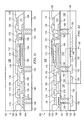
- FIGS. 3 a - 3 e illustrate a method of forming a semiconductor device having an integrated passive device (IPD) connected to an inductor and capacitor, the inductor and capacitor are formed over the IPD;
- IPD integrated passive device
- FIG. 4 illustrates a semiconductor device having an IPD connected to an inductor and capacitor, an interconnect structure is formed over the inductor;
- FIG. 5 illustrates a semiconductor device having an IPD connected to an inductor and capacitor, an inductor structure is formed over a back-surface of the IPD;
- FIG. 6 illustrates a semiconductor device having an IPD connected to an inductor and capacitor, TSVS of the IPD are formed together with a bottom electrode of the capacitor;
- FIG. 7 illustrates a semiconductor device having an IPD connected to an inductor and capacitor, the inductor and capacitor are formed over the IPD, a second inductor is formed over a top surface of the IPD.
- Front-end manufacturing involves the formation of a plurality of die on the surface of a semiconductor wafer.
- Each die on the wafer contains active and passive electrical components which are electrically connected to form functional electrical circuits.
- Active electrical components such as transistors, have the ability to control the flow of electrical current.
- Passive electrical components such as capacitors, inductors, resistors, and transformers, create a relationship between voltage and current necessary to perform electrical circuit functions.
- Passive and active components are formed on the surface of the semiconductor wafer by a series of process steps including doping, deposition, photolithography, etching, and planarization.
- Doping introduces impurities into the semiconductor material by techniques such as ion implantation or thermal diffusion.
- the doping process modifies the electrical conductivity of semiconductor material in active devices, transforming the semiconductor material into a permanent insulator, permanent conductor, or changing the way the semiconductor material changes in conductivity in response to an electric field.
- Transistors contain regions of varying types and degrees of doping arranged as necessary to enable the transistor to promote or restrict the flow of electrical current upon the application of an electric field.
- Active and passive components are formed by layers of materials with different electrical properties.
- the layers can be formed by a variety of deposition techniques determined in part by the type of material being deposited. For example, thin film deposition may involve chemical vapor deposition (CVD), physical vapor deposition (PVD), electrolytic plating, and electroless plating processes.
- CVD chemical vapor deposition
- PVD physical vapor deposition
- electrolytic plating electroless plating processes.
- Each layer is generally patterned to form portions of active components, passive components, or electrical connections between components.
- the layers can be patterned using photolithography, which involves the deposition of light sensitive material, e.g., photoresist, over the layer to be patterned.
- a pattern is transferred from a photomask to the photoresist using light.
- the portion of the photoresist pattern subjected to light is removed using a solvent, exposing portions of the underlying layer to be patterned.
- the remainder of the photoresist is removed, leaving behind a patterned layer.
- some types of materials are patterned by directly depositing the material into the areas or voids formed by a previous deposition/etch process using techniques such as electrolytic plating.
- Planarization can be used to remove material from the surface of the wafer and produce a uniformly flat surface. Planarization involves polishing the surface of the wafer with a polishing pad. An abrasive material and corrosive chemical are added to the surface of the wafer during polishing. The combined mechanical action of the abrasive and corrosive action of the chemical removes any irregular topography, resulting in a uniformly flat surface.
- Back-end manufacturing refers to cutting or singulating the finished wafer into the individual die and then packaging the die for structural support and environmental isolation.
- the wafer is scored and broken along non-functional regions of the wafer called saw streets or scribes.
- the wafer is singulated using a laser cutting device or saw blade.
- the individual die are mounted to a package substrate that includes pins or contact pads for interconnection with other system components.
- Contact pads formed over the semiconductor die are then connected to contact pads within the package.
- the electrical connections can be made with solder bumps, stud bumps, conductive paste, or wirebonds.
- An encapsulant or other molding material is deposited over the package to provide physical support and electrical isolation.
- the finished package is then inserted into an electrical system and the functionality of the semiconductor device is made available to the other system components.
- FIG. 1 illustrates electronic device 10 having a chip carrier substrate or printed circuit board (PCB) 12 with a plurality of semiconductor packages mounted on its surface.
- Electronic device 10 may have one type of semiconductor package, or multiple types of semiconductor packages, depending on the application. The different types of semiconductor packages are shown in FIG. 1 for purposes of illustration.
- Electronic device 10 may be a stand-alone system that uses the semiconductor packages to perform an electrical function.
- electronic device 10 may be a subcomponent of a larger system.
- electronic device 10 may be a graphics card, network interface card, or other signal processing card that can be inserted into a computer.
- the semiconductor package can include microprocessors, memories, application specific integrated circuits (ASICs), logic circuits, analog circuits, RF circuits, discrete devices, or other semiconductor die or electrical components.
- PCB 12 provides a general substrate for structural support and electrical interconnect of the semiconductor packages mounted on the PCB.
- Conductive signal traces 14 are formed on a surface or within layers of PCB 12 using evaporation, electrolytic plating, electroless plating, screen printing, PVD, or other suitable metal deposition process. Signal traces 14 provide for electrical communication between each of the semiconductor packages, mounted components, and other external system components. Traces 14 also provide power and ground connections to each of the semiconductor packages.
- a semiconductor device has two packaging levels.
- First level packaging is the technique for mechanically and electrically attaching the semiconductor die to a carrier.
- Second level packaging involves mechanically and electrically attaching the carrier to the PCB.
- a semiconductor device may only have the first level packaging where the die is mechanically and electrically mounted directly to the PCB.
- first level packaging including wire bond package 16 and flip chip 18
- second level packaging including ball grid array (BGA) 20 , bump chip carrier (BCC) 22 , dual in-line package (DIP) 24 , land grid array (LGA) 26 , multi-chip module (MCM) 28 , quad flat non-leaded package (QFN) 30 , and quad flat package 32 .
- BGA ball grid array
- BCC bump chip carrier
- DIP dual in-line package
- LGA land grid array
- MCM multi-chip module
- QFN quad flat non-leaded package
- quad flat package 32 quad flat package
- electronic device 10 includes a single attached semiconductor package, while other embodiments call for multiple interconnected packages.
- manufacturers can incorporate pre-made components into electronic devices and systems. Because the semiconductor packages include sophisticated functionality, electronic devices can be manufactured using cheaper components and a shorter manufacturing process. The resulting devices are less likely to fail and less expensive to manufacture resulting in lower costs for consumers.
- FIG. 2 a illustrates further detail of DIP 24 mounted on PCB 12 .
- DIP 24 includes semiconductor die 34 having contact pads 36 .
- Semiconductor die 34 includes an active area containing analog or digital circuits implemented as active devices, passive devices, conductive layers, and dielectric layers formed within semiconductor die 34 and are electrically interconnected according to the electrical design of the die.
- the circuit may include one or more transistors, diodes, inductors, capacitors, resistors, and other circuit elements formed within the active area of die 34 .
- Contact pads 36 are made with a conductive material, such as aluminum (Al), copper (Cu), tin (Sn), nickel (Ni), gold (Au), or silver (Ag), and are electrically connected to the circuit elements formed within die 34 .
- Contact pads 36 are formed by PVD, CVD, electrolytic plating, or electroless plating process.
- semiconductor die 34 is mounted to a carrier 38 using a gold-silicon eutectic layer or adhesive material such as thermal epoxy.
- the package body includes an insulative packaging material such as plastic or ceramic.
- Conductor leads 40 are connected to carrier 38 and wire bonds 42 are formed between leads 40 and contact pads 36 of die 34 as a first level packaging.
- Encapsulant 44 is deposited over the package for environmental protection by preventing moisture and particles from entering the package and contaminating die 34 , contact pads 36 , or wire bonds 42 .
- DIP 24 is connected to PCB 12 by inserting leads 40 into holes formed through PCB 12 .
- Solder material 46 is flowed around leads 40 and into the holes to physically and electrically connect DIP 24 to PCB 12 .
- Solder material 46 can be any metal or electrically conductive material, e.g., Sn, lead (Pb), Au, Ag, Cu, zinc (Zn), bismuthinite (Bi), and alloys thereof, with an optional flux material.
- the solder material can be eutectic Sn/Pb, high-lead, or lead-free.
- FIG. 2 b illustrates further detail of BCC 22 mounted on PCB 12 .
- Semiconductor die 16 is connected to a carrier by wire bond style first level packaging.
- BCC 22 is mounted to PCB 12 with a BCC style second level packaging.
- Semiconductor die 16 having contact pads 48 is mounted over a carrier using an underfill or epoxy-resin adhesive material 50 .
- Semiconductor die 16 includes an active area containing analog or digital circuits implemented as active devices, passive devices, conductive layers, and dielectric layers formed within semiconductor die 16 and are electrically interconnected according to the electrical design of the die.
- the circuit may include one or more transistors, diodes, inductors, capacitors, resistors, and other circuit elements formed within the active area of die 16 .
- Contact pads 48 are made with a conductive material, such as Al, Cu, Sn, Ni, Au, or Ag, and are electrically connected to the circuit elements formed within die 16 .
- Contact pads 48 are formed by PVD, CVD, electrolytic plating, or electroless plating process.
- Wire bonds 54 and bond pads 56 and 58 electrically connect contact pads 48 of semiconductor die 16 to contact pads 52 of BCC 22 forming the first level packaging.
- Molding compound or encapsulant 60 is deposited over semiconductor die 16 , wire bonds 54 , contact pads 48 , and contact pads 52 to provide physical support and electrical isolation for the device.
- Contact pads 64 are formed on a surface of PCB 12 using evaporation, electrolytic plating, electroless plating, screen printing, PVD, or other suitable metal deposition process and are typically plated to prevent oxidation. Contact pads 64 electrically connect to one or more conductive signal traces 14 . Solder material is deposited between contact pads 52 of BCC 22 and contact pads 64 of PCB 12 . The solder material is reflowed to form bumps 66 which form a mechanical and electrical connection between BCC 22 and PCB 12 .
- semiconductor die 18 is mounted face down to carrier 76 with a flip chip style first level packaging.
- BGA 20 is attached to PCB 12 with a BGA style second level packaging.
- Active area 70 containing analog or digital circuits implemented as active devices, passive devices, conductive layers, and dielectric layers formed within semiconductor die 18 is electrically interconnected according to the electrical design of the die.
- the circuit may include one or more transistors, diodes, inductors, capacitors, resistors, and other circuit elements formed within active area 70 of semiconductor die 18 .
- Semiconductor die 18 is electrically and mechanically attached to the carrier 76 through a large number of individual conductive solder bumps or balls 78 .
- Solder bumps 78 are formed on bump pads or interconnect sites 80 , which are disposed on active areas 70 .
- Bump pads 80 are made with a conductive material, such as Al, Cu, Sn, Ni, Au, or Ag, and are electrically connected to the circuit elements formed in active area 70 .
- Bump pads 80 are formed by PVD, CVD, electrolytic plating, or electroless plating process.
- Solder bumps 78 are electrically and mechanically connected to contact pads or interconnect sites 82 on carrier 76 by a solder reflow process.
- BGA 20 is electrically and mechanically attached to PCB 12 by a large number of individual conductive solder bumps or balls 86 .
- the solder bumps are formed on bump pads or interconnect sites 84 .
- the bump pads 84 are electrically connected to interconnect sites 82 through conductive lines 90 routed through carrier 76 .
- Contact pads 88 are formed on a surface of PCB 12 using evaporation, electrolytic plating, electroless plating, screen printing, PVD, or other suitable metal deposition process and are typically plated to prevent oxidation.
- Contact pads 88 electrically connect to one or more conductive signal traces 14 .
- the solder bumps 86 are electrically and mechanically connected to contact pads or bonding pads 88 on PCB 12 by a solder reflow process.
- Molding compound or encapsulant 92 is deposited over semiconductor die 18 and carrier 76 to provide physical support and electrical isolation for the device.
- the flip chip semiconductor device provides a short electrical conduction path from the active devices on semiconductor die 18 to conduction tracks on PCB 12 in order to reduce signal propagation distance, lower capacitance, and achieve overall better circuit performance.
- the semiconductor die 18 can be mechanically and electrically attached directly to PCB 12 using flip chip style first level packaging without carrier 76 .
- FIGS. 3 a - 3 e illustrate a method of forming semiconductor device 100 having an integrated passive device (IPD) with connections to an inductor and capacitor, the inductor and capacitor may be formed over different surfaces or substrates of IPD 102 .
- semiconductor substrate or high resistivity substrate 102 is first provided.
- the substrate of IPD 102 includes silicon (Si), other semi-conducting materials, or a high-resistivity substrate material and may include an optional pre-built circuit.
- An active region is formed within IPD 102 that includes one or more integrated circuits and passive or active devices used by semiconductor device 100 for implementing radio-frequency (RF), or other high-frequency applications.
- RF radio-frequency
- Insulation layer 104 is formed over the substrate of IPD 102 .
- Insulation layer 104 is typically made with silicon dioxide (SiO2), but can also be made with silicon nitride (Si3N4), silicon oxynitride (SiON), tantalum pentoxide (Ta2O5), zircon (ZrO2), aluminum oxide (Al2O3), or other material having dielectric insulation properties.
- the deposition of insulation layer 104 involves CVD, or thermal oxidation, for example.
- Insulation layer 104 is formed conformally over the substrate of IPD 102 and a conductive material is deposited into the vias to form through-silicon vias (TSVs) 106 .
- TSVs 106 may be blind (as indicated by 107 on FIG. 3 a ) or may be exposed at the back-surface of the substrate of IPD 102 .
- Conductive materials are formed in TSVs 106 using an evaporation, electrolytic plating, electroless plating, screen printing, or another suitable metal deposition process and include Al, Cu, Sn, Ni, Au, or Ag or another conductive material.
- various passive devices including capacitors, resistors and inductors are formed over a surface of the substrate of IPD 102 .
- Metal layer 108 is deposited over insulation layer 104 and is electrically connected to TSVs 106 .
- Resistive layer 110 is deposited over metal layer 108 and insulation layer 104 and includes tantalum silicide (TaxSiy) or other metal silicides, TaN, nichrome (NiCr), TiN, or doped poly-silicon.
- Dielectric layer 112 is deposited over resistive layer 110 .
- Dielectric layer 112 can be silicon nitride (Si3N4), tantalum oxide (Ta2O5), hafnium oxide (HfO2), or a dielectric film material.
- resistive layer 110 formed between dielectric layer 112 and metal layer 108 , is optional.
- Insulation layer 114 is deposited over insulation layer 104 , metal layer 108 , resistive layer 110 , and dielectric layer 112 .
- Metal layer 116 includes a conductive material and is deposited over insulation layer 114 using a PVD, CVD, electrolytic plating, or electroless plating process.
- the combination of metal, insulation, dielectric, and resistive layers forms one or more passive devices over a surface of the substrate of IPD 102 .
- Box 122 shown on FIG. 3 b indicates a resistor structure formed over the substrate of IPD 102 that includes portions of resistive layer 110 and metal layer 116 .
- Box 124 indicates a capacitor structure formed over IPD 102 that includes portions of metal layer 108 , resistive layer 110 , dielectric layer 112 and metal layer 116 . Portions of metal layers 108 and 116 form the electrodes of the capacitor indicated by box 124 .
- different combinations of passive devices, RF circuitry, or other electronic circuits are formed over the substrate of IPD 102 to provide the necessary functionality of semiconductor device 100 .
- Insulation layer 120 is deposited over the substrate of IPD 102 to provide electrical isolation and physical protection to semiconductor device 100 . Insulation layer 120 is patterned to expose portions of metal layer 116 .
- Temporary wafer carrier 126 is mounted over device 100 using adhesion layer 128 .
- Temporary wafer carrier 126 includes a stiff material such as a glass wafer or flexible tape substrate and facilitates the build-up process performed over the back-surface of the substrate of IPD 102 .
- Temporary wafer carrier 126 can also include certain flexible tapes, such as high temperature back grinding tape, to support the wafer.
- Adhesion layer 128 is deposited using spin coating, or printing, and may include a laminated polymer adhesive or an ultra-violet (UV) curable liquid adhesive. In one embodiment, adhesion layer 128 is light, heat or mechanically releasable.
- a backgrinding process is used to remove a portion of IPD 102 to expose conductive TSVs 106 .
- the backgrinding process may involve mechanical griding, chemical-mechanical polishing (CMP), wet etching, or plasma etching. After backgrinding, the metal in TSVs 106 is exposed.
- additional conductive and insulation layers are formed over a back-surface of the substrate of IPD 102 .
- insulation layer 130 is deposited over IPD 102 .
- Insulation layer 130 is patterned to expose TSVs 106 of the substrate of IPD 102 .
- Metal layer 132 is deposited and patterned over insulation layer 130 .
- Metal layer 132 is electrically connected to TSVs 106 .
- TSVs 106 metal layer 132 is also connected to the resistor, capacitor, and other circuit elements formed over the back-surface of IPD 102 .
- Insulation layer 134 is deposited over metal layer 132 to provide electrical isolation and mechanical support to semiconductor device 100 .
- Insulation layer 134 may be deposited using spin coating, printing, lamination or molding, for example. As shown in FIG. 3 d , metal layer 132 is patterned such that a portion of metal layer 132 forms an inductor structure indicated by box 136 . In alternative embodiments, additional metal, dielectric, or insulation layers may be formed over the substrate of IPD 102 to form additional passive circuit elements over a back-surface of IPD 102 .
- the interconnect structure includes solder bumps 138 deposited over insulation layer 120 and electrically connected to metal layer 116 .
- Bumps 138 include an electrically conductive material such as solder or other electrically conductive material, e.g., Sn, Pb, Au, Ag, Cu, Zn, Bi, and alloys thereof.
- the solder material can be eutectic Sn/Pb, high lead, or lead free.
- the solder material is deposited over the patterned regions of insulation layer 120 and is reflowed to form bumps 138 .
- other interconnect structures such as stud bumping, wirebonds or conductive pillars are connected to semiconductor device 100 to allow for the connection of external system components.
- a semiconductor device is formed that includes passive circuit elements formed over the surfaces of a semiconductor substrate.
- the semiconductor substrate includes an IPD that provides integrated circuits and functionality for RF, or other high-frequency applications.
- a capacitor is formed over a first surface of the IPD, while an inductor is formed over the opposite surface of the IPD.
- the capacitor may also be formed vertically over a central region of the inductor. The dimensions of the capacitor are not limited by those of the inductor as when trying to form a capacitor at the center of the inductor.
- the passive circuit elements are formed in an IPD and are connected with each other using 2D and 3D interconnections.
- a plurality of TSVs are formed within the substrate of the IPD. The TSVs allow for the formation of integrated circuits that interconnect the IPD with more flexibility and greater functionality.
- FIG. 4 illustrates semiconductor device 200 having an IPD connecting an inductor, resistor, and capacitor, an interconnect structure is formed over the inductor.
- the substrate of IPD 202 includes Si, other semi-conducting materials, or a high-resistivity substrate material.
- the substrate of IPD 202 may include an optional prebuilt circuit.
- An active region is formed over the substrate of IPD 202 that includes one or more integrated circuits and passive or active devices used by semiconductor device 200 . Vias are formed in the substrate of IPD 202 using DRIE, laser etching, laser drilling, or another etching process.
- Insulation layer 204 is formed over the substrate of IPD 202 and includes a material having dielectric insulation properties.
- insulation layer 204 involves PVD, CVD, printing, sintering, or thermal oxidation, for example.
- Insulation layer 204 is formed conformally over the substrate of IPD 202 and a conductive material is deposited into the vias to form TSVs 206 .
- TSVs 206 are exposed by backgrinding of the substrate of IPD 202 .
- the conductive materials of TSVs 206 are formed using an evaporation, electrolytic plating, electroless plating, screen printing, or another suitable metal deposition process and include Al, Cu, Sn, Ni, Au, or Ag or another conductive material.
- Metal layer 208 is deposited over insulation layer 204 and is electrically connected to TSVs 206 .
- Resistive layer 210 is deposited over metal layer 208 and insulation layer 204 and includes TaxSiy or other metal silicides, TaN, NiCr, TiN, or doped poly-silicon.
- Dielectric layer 212 is deposited over resistive layer 210 .
- Dielectric layer 212 can be Si3N4, SiON, Ta2O5, HfO2, or a dielectric film material.
- Insulation layer 214 is deposited over insulation layer 204 , metal layer 208 , resistive layer 210 , and dielectric layer 212 .
- Metal layer 216 includes a conductive material and is deposited over insulation layer 214 using a PVD, CVD, electrolytic plating, or electroless plating process.
- the combination of metal, insulation, dielectric, and resistive layers forms one or more passive devices over a surface of IPD 202 .
- By patterning each layer, various resistors, inductors, or capacitors are formed over a surface of IPD 202 .
- Encapsulant 220 such as a molding compound, is deposited over metal layer 216 to provide electrical isolation and physical support to semiconductor device 200 .
- Molding compound 220 includes epoxy acrylate or other polymer material with or without filler, and is applied by paste printing, compressive molding, or other molding processes. In an alternative embodiment, however, molding compound 220 is replaced by a permanently bonding adhesive material.
- An optional mechanical carrier 222 is mounted to adhesive material 220 to provide additional physical support to device 200 .
- Mechanical carrier 222 may include a conductive layer to provide electro-magnetic interference (EMI) protection to device 200 .
- mechanical carrier 222 may include heat sinks, thermal sheets, or heat spreaders to facilitate the removal of thermal energy from device 200 .
- EMI electro-magnetic interference
- Insulation layer 224 is deposited over a back side of IPD 202 . Insulation layer 224 is patterned to expose TSVs 206 of IPD 202 . Metal layer 226 is deposited and patterned over insulation layer 224 . Metal layer 226 is electrically connected to TSVs 206 . Using TSVs 206 , metal layer 226 is also connected to the resistor, capacitor, and other circuit elements formed over the back-surface of IPD 202 . Insulation layer 228 is deposited over metal layer 226 to provide electrical isolation and mechanical support to semiconductor device 200 . Insulation layer 228 may be deposited using spin coating, printing, lamination or molding, for example. Metal layer 226 forms an inductor structure over the back surface of IPD 202 . In alternative embodiments, additional metal, dielectric, or insulation layers may be deposited over IPD 202 to form additional passive circuit elements.
- interconnect structure is connected to device 200 .
- the interconnect structure includes solder bumps 230 deposited over insulation layer 228 and electrically connected to metal layer 226 .
- Bumps 230 include an electrically conductive material such as solder. The conductive material is deposited over the patterned regions of insulation layer 228 and is reflowed to form bumps 230 .
- other interconnect structures such as stud bumping, wirebonds or conductive pillars are connected to semiconductor device 200 to allow for the connection of external system components.
- FIG. 5 illustrates semiconductor device 300 having an IPD connected to an inductor and capacitor, an inductor structure is formed over a front-surface of the IPD.
- the substrate of IPD 302 includes Si, other semi-conducting materials, or a high-resistivity substrate material.
- the substrate of IPD 302 may include an optional prebuilt circuit.
- An active region is formed over the substrate of IPD 302 that includes one or more integrated circuits and passive or active devices used by semiconductor device 300 . Vias are formed in IPD 302 using laser etching, laser drilling, or another etching process.
- Insulation layer 304 is formed over IPD 302 and includes a material having dielectric insulation properties.
- insulation layer 304 involves PVD, CVD, printing, sintering, or thermal oxidation, for example.
- Insulation layer 304 is formed conformally over IPD 302 and a conductive material is deposited into the vias to form TSVs 306 .
- TSVs 306 are exposed by backgrinding of IPD 302 .
- the conductive material of TSVs 306 is formed using an evaporation, electrolytic plating, electroless plating, screen printing, or another suitable metal deposition process and include Al, Cu, Sn, Ni, Au, or Ag or another conductive material.
- Metal layer 308 is deposited over insulation layer 304 and is electrically connected to TSVs 306 . As shown in FIG. 5 , metal layer 308 is patterned to form an inductor structure over the top surface of IPD 302 . The inductor is connected to TSVs 306 of IPD 302 . Insulation layer 310 is formed over metal layer 308 to provide electrical insulation and mechanical support for semiconductor device 300 . Insulation layer 310 is deposited using spin coating, printing, or molding, for example. In an alternative embodiment, additional resistive layers are formed over the top surface of IPD 302 to form a resistor structure connected to metal layer 308 .
- Insulation layer 312 is deposited over a back surface of IPD 302 . Insulation layer 312 is patterned to expose TSVs 306 of IPD 302 . Metal layer 314 is deposited and patterned over insulation layer 312 . Metal layer 314 is electrically connected to TSVs 306 . Using TSVs 306 , metal layer 314 is also connected to the inductor structure and other circuitry formed over IPD 302 by metal layer 308 . Resistive layer 316 is deposited over metal layer 314 and insulation layer 312 and includes TaxSiy or other metal silicides, TaN, NiCr, TiN, or doped poly-silicon. Dielectric layer 318 is deposited over resistive layer 316 .
- Dielectric layer 318 can be Si3N4, Ta2O5, HfO2, or a dielectric film material.
- Insulation layer 320 is deposited over insulation layer 312 , metal layer 314 , resistive layer 316 , and dielectric layer 318 .
- Metal layer 322 includes a conductive material and is deposited over insulation layer 320 using a PVD, CVD, electrolytic plating, or electroless plating process. The combination of metal, insulation, dielectric, and resistive layers forms one or more passive devices over a surface of IPD 302 . By patterning each layer, various resistors, inductors, or capacitors are formed over a surface of IPD 302 .
- Insulation layer 324 is deposited over metal layer 322 . Insulation layer 324 provides electrical insulation and mechanical support to device 300 and is patterned to expose portions of metal layer 322 . Insulation layer 324 may be deposited using spin coating, printing, lamination or molding, for example.
- interconnect structure is connected to device 300 .
- the interconnect structure includes solder bumps 326 deposited over insulation layer 324 and electrically connected to metal layer 322 .
- Bumps 326 include an electrically conductive material such as solder. The conductive material is deposited over the patterned regions of insulation layer 324 and is reflowed to form bumps 326 .
- other interconnect structures such as stud bumping, wirebonds or conductive pillars are connected to semiconductor device 300 to allow for the connection of external system components.
- FIG. 6 illustrates semiconductor device 400 having an IPD connected to an inductor and capacitor, the metal in TSVs of the IPD is formed together with a bottom electrode of the capacitor.
- the substrate of IPD 402 includes Si, other semi-conducting materials, or a high-resistivity substrate material.
- An active region is formed over IPD 402 that includes one or more integrated circuits and passive or active devices used by semiconductor device 400 . Vias are formed in IPD 402 using DRIE, laser etching, laser drilling, or another etching process.
- Insulation layer 404 is formed over IPD 402 .
- the deposition of insulation layer 404 involves PVD, CVD, printing, sintering, or thermal oxidation, for example.
- Insulation layer 404 is formed conformally over IPD 402 .
- Metal layer 406 is deposited over insulation layer 404 and fills in the vias to form conductive TSVs in IPD 402 . Additional CMP processes may be applied to smooth the top surface of metal 406 .
- Resistive layer 408 is deposited over metal layer 406 and insulation layer 404 and includes TaxSiy or other metal silicides, TaN, NiCr, TiN, or doped poly-silicon. In one embodiment, the seed layer etching for plating metal layer 406 is performed after the patterning of resistive layer 408 is complete.
- Dielectric layer 410 is deposited over resistive layer 408 .
- Dielectric layer 410 can be Si3N4, Ta2O5, HfO2, or a dielectric film material.
- Insulation layer 412 is deposited over insulation layer 404 , metal layer 406 , resistive layer 408 , and dielectric layer 410 .
- Metal layer 414 includes a conductive material and is deposited over insulation layer 412 using a PVD, CVD, electrolytic plating, or electroless plating process.
- the combination of metal, insulation, dielectric, and resistive layers forms one or more passive devices over a surface of IPD 402 .
- a capacitor is formed over IPD 402 (indicated by box 426 ).
- One electrode of capacitor 426 is formed by a portion of metal layer 406 .
- Box 428 indicates a resistor structure formed over IPD 402 that includes portions of resistive layer 408 and metal layer 414 .
- different combinations of passive devices, RF circuitry, or other electronic circuits are formed over IPD 402 to provide the necessary functionality of semiconductor device 400 .
- Insulation layer 416 is deposited over IPD 402 to provide electrical isolation and physical protection to semiconductor device 400 .
- Insulation layer 420 is deposited over IPD 402 .
- Insulation layer 420 is patterned to expose TSVs 406 of IPD 402 .
- Metal layer 422 is deposited and patterned over insulation layer 420 .
- Metal layer 422 is electrically connected to TSVs 406 .
- TSVs 406 metal layer 422 is connected to the resistor and capacitor structures formed over the back-surface of IPD 402 .
- Insulation layer 424 is deposited over metal layer 422 to provide electrical isolation and mechanical support to semiconductor device 400 . Insulation layer 424 may be deposited using spin coating, printing, lamination or molding, for example.
- interconnect structure is connected to device 400 .
- the interconnect structure includes solder bumps 418 deposited over insulation layer 416 and electrically connected to metal layer 414 .
- Bumps 418 include an electrically conductive material that is deposited over the patterned regions of insulation layer 416 and reflowed to form bumps 418 .
- other interconnect structures such as stud bumping, wirebonds or conductive pillars are connected to semiconductor device 400 to allow for the connection of external system components.
- FIG. 7 illustrates semiconductor device 500 having an IPD connected to an inductor and capacitor, the inductor and capacitor are formed over the IPD, a second inductor is formed over a top surface of the IPD.
- IPD 502 includes Si, other semi-conducting materials, or a high-resistivity substrate material.
- An active region is formed over IPD 502 that includes one or more integrated circuits and passive or active devices used by semiconductor device 500 . Vias are formed in IPD 502 using laser etching, laser drilling, or another etching process. Insulation layer 504 is formed over IPD 502 .
- Insulation layer 504 is typically made with SiO2, but can also be made with Si3N4, SiON, Ta2O5, ZrO2, Al2O3, or other material having dielectric insulation properties.
- the deposition of insulation layer 504 involves PVD, CVD, printing, sintering, or thermal oxidation, for example. Insulation layer 504 is formed conformally over IPD 502 and a conductive material is deposited into the vias to form TSVs 506 .
- Metal layer 508 is deposited over insulation layer 504 and is electrically connected to TSVs 506 .
- Resistive layer 510 is deposited over metal layer 508 and insulation layer 504 and includes TaxSiy or other metal silicides, TaN, NiCr, TiN, or doped poly-silicon.
- Dielectric layer 512 is deposited over resistive layer 510 .
- Dielectric layer 512 can be SiN, Ta2O5, HfO2, or a dielectric film material.
- Insulation layer 514 is deposited over insulation layer 504 , metal layer 508 , resistive layer 510 , and dielectric layer 512 .
- Metal layer 516 includes a conductive material and is deposited over insulation layer 514 using a PVD, CVD, electrolytic plating, or electroless plating process.
- the combination of metal, insulation, dielectric, and resistive layers forms one or more passive devices over a surface of IPD 502 .
- Box 518 shown on FIG. 7 indicates a resistor structure formed over IPD 502 that includes portions of resistive layer 510 and metal layer 516 .
- Box 520 indicates a capacitor structure formed over IPD 502 that includes portions of metal layer 508 , resistive layer 510 , dielectric layer 512 and metal layer 516 . Portions of metal layers 508 and 516 form the electrodes of the capacitor indicated by box 520 .
- Box 522 indicates an inductor structure formed by portions of metal layer 516 .
- different combinations of passive devices, RF circuitry, or other electronic circuits are formed over IPD 502 to provide the necessary functionality of semiconductor device 500 .
- Insulation layer 524 is deposited over IPD 502 to provide electrical isolation and physical protection to semiconductor device 500 .
- Insulation layer 528 is deposited over IPD 502 .
- Insulation layer 528 is patterned to expose TSVs 506 of IPD 502 .
- Metal layer 530 is deposited and patterned over insulation layer 528 .
- Metal layer 530 is electrically connected to TSVs 506 .
- TSVs 506 metal layer 530 is also connected to the resistor, capacitor, inductor and other circuit elements formed over the back-surface of IPD 502 .
- Insulation layer 534 is deposited over metal layer 530 to provide electrical isolation and mechanical support to semiconductor device 500 . Insulation layer 534 may be deposited using spin coating, printing, lamination or molding, for example. As shown in FIG.
- metal layer 530 is patterned such that a portion of metal layer 530 forms an inductor structure indicated by box 532 .
- additional metal, dielectric, or insulation layers may be formed over IPD 502 to form additional passive circuit elements over a back-surface of IPD 502 .
- interconnect structure is connected to device 500 .
- the interconnect structure includes solder bumps 526 deposited over insulation layer 524 and electrically connected to metal layer 516 .
- Bumps 526 include an electrically conductive material deposited over the patterned regions of insulation layer 524 and reflowed to form bumps 526 .
- other interconnect structures such as stud bumping, wirebonds or conductive pillars are connected to semiconductor device 500 to allow for the connection of external system components.
Abstract
Description
Claims (18)
Priority Applications (2)
| Application Number | Priority Date | Filing Date | Title |
|---|---|---|---|
| US12/212,524 US7772081B2 (en) | 2008-09-17 | 2008-09-17 | Semiconductor device and method of forming high-frequency circuit structure and method thereof |
| US12/826,368 US8110477B2 (en) | 2008-09-17 | 2010-06-29 | Semiconductor device and method of forming high-frequency circuit structure and method thereof |
Applications Claiming Priority (1)
| Application Number | Priority Date | Filing Date | Title |
|---|---|---|---|
| US12/212,524 US7772081B2 (en) | 2008-09-17 | 2008-09-17 | Semiconductor device and method of forming high-frequency circuit structure and method thereof |
Related Child Applications (1)
| Application Number | Title | Priority Date | Filing Date |
|---|---|---|---|
| US12/826,368 Continuation US8110477B2 (en) | 2008-09-17 | 2010-06-29 | Semiconductor device and method of forming high-frequency circuit structure and method thereof |
Publications (2)
| Publication Number | Publication Date |
|---|---|
| US20100065942A1 US20100065942A1 (en) | 2010-03-18 |
| US7772081B2 true US7772081B2 (en) | 2010-08-10 |
Family
ID=42006458
Family Applications (2)
| Application Number | Title | Priority Date | Filing Date |
|---|---|---|---|
| US12/212,524 Active 2029-01-29 US7772081B2 (en) | 2008-09-17 | 2008-09-17 | Semiconductor device and method of forming high-frequency circuit structure and method thereof |
| US12/826,368 Active 2028-11-14 US8110477B2 (en) | 2008-09-17 | 2010-06-29 | Semiconductor device and method of forming high-frequency circuit structure and method thereof |
Family Applications After (1)
| Application Number | Title | Priority Date | Filing Date |
|---|---|---|---|
| US12/826,368 Active 2028-11-14 US8110477B2 (en) | 2008-09-17 | 2010-06-29 | Semiconductor device and method of forming high-frequency circuit structure and method thereof |
Country Status (1)
| Country | Link |
|---|---|
| US (2) | US7772081B2 (en) |
Cited By (41)
| Publication number | Priority date | Publication date | Assignee | Title |
|---|---|---|---|---|
| US20090294959A1 (en) * | 2008-05-28 | 2009-12-03 | Siliconware Precision Industries Co., Ltd. | Semiconductor package device, semiconductor package structure, and fabrication methods thereof |
| US20100140805A1 (en) * | 2008-12-10 | 2010-06-10 | Hung-Pin Chang | Bump Structure for Stacked Dies |
| US20100171197A1 (en) * | 2009-01-05 | 2010-07-08 | Hung-Pin Chang | Isolation Structure for Stacked Dies |
| US20100230783A1 (en) * | 2009-03-13 | 2010-09-16 | Nec Electronics Corporation | Semiconductor device |
| US20110042576A1 (en) * | 2009-08-20 | 2011-02-24 | Icemos Technology Ltd. | Direct wafer-bonded through-hole photodiode |
| US20110068468A1 (en) * | 2008-12-08 | 2011-03-24 | Stats Chippac, Ltd. | Semiconductor Package with Semiconductor Core Structure and Method of Forming the Same |
| US20110068466A1 (en) * | 2009-09-22 | 2011-03-24 | Taiwan Semiconductor Manufacturing Company, Ltd. | Wafer Backside Interconnect Structure Connected to TSVs |
| US20110210453A1 (en) * | 2008-12-11 | 2011-09-01 | Panasonic Corporation | Method for designing electronic system |
| US8035213B2 (en) | 2007-10-22 | 2011-10-11 | Advanced Semiconductor Engineering, Inc. | Chip package structure and method of manufacturing the same |
| US20110304014A1 (en) * | 2010-06-10 | 2011-12-15 | Stmicroelectronics (Tours) Sas | Passive integrated circuit |
| US8446000B2 (en) | 2009-11-24 | 2013-05-21 | Chi-Chih Shen | Package structure and package process |
| US8466059B2 (en) | 2010-03-30 | 2013-06-18 | Taiwan Semiconductor Manufacturing Company, Ltd. | Multi-layer interconnect structure for stacked dies |
| US8541883B2 (en) | 2011-11-29 | 2013-09-24 | Advanced Semiconductor Engineering, Inc. | Semiconductor device having shielded conductive vias |
| US8592947B2 (en) | 2010-12-08 | 2013-11-26 | International Business Machines Corporation | Thermally controlled refractory metal resistor |
| US8643167B2 (en) | 2011-01-06 | 2014-02-04 | Advanced Semiconductor Engineering, Inc. | Semiconductor package with through silicon vias and method for making the same |
| US8692362B2 (en) | 2010-08-30 | 2014-04-08 | Advanced Semiconductor Engineering, Inc. | Semiconductor structure having conductive vias and method for manufacturing the same |
| US8786060B2 (en) | 2012-05-04 | 2014-07-22 | Advanced Semiconductor Engineering, Inc. | Semiconductor package integrated with conformal shield and antenna |
| US8786098B2 (en) | 2010-10-11 | 2014-07-22 | Advanced Semiconductor Engineering, Inc. | Semiconductor element having conductive vias and semiconductor package having a semiconductor element with conductive vias and method for making the same |
| US8841751B2 (en) | 2013-01-23 | 2014-09-23 | Advanced Semiconductor Engineering, Inc. | Through silicon vias for semiconductor devices and manufacturing method thereof |
| US8853819B2 (en) | 2011-01-07 | 2014-10-07 | Advanced Semiconductor Engineering, Inc. | Semiconductor structure with passive element network and manufacturing method thereof |
| US20140306261A1 (en) * | 2013-04-15 | 2014-10-16 | Samsung Electronics Co., Ltd. | Electronic device package and package substrate for the same |
| US8865520B2 (en) | 2010-08-27 | 2014-10-21 | Advanced Semiconductor Engineering, Inc. | Carrier bonding and detaching processes for a semiconductor wafer |
| US8900994B2 (en) | 2011-06-09 | 2014-12-02 | Taiwan Semiconductor Manufacturing Company, Ltd. | Method for producing a protective structure |
| US8937387B2 (en) | 2012-11-07 | 2015-01-20 | Advanced Semiconductor Engineering, Inc. | Semiconductor device with conductive vias |
| US8952542B2 (en) | 2012-11-14 | 2015-02-10 | Advanced Semiconductor Engineering, Inc. | Method for dicing a semiconductor wafer having through silicon vias and resultant structures |
| US8963316B2 (en) | 2012-02-15 | 2015-02-24 | Advanced Semiconductor Engineering, Inc. | Semiconductor device and method for manufacturing the same |
| US8975157B2 (en) | 2012-02-08 | 2015-03-10 | Advanced Semiconductor Engineering, Inc. | Carrier bonding and detaching processes for a semiconductor wafer |
| US8987734B2 (en) | 2013-03-15 | 2015-03-24 | Advanced Semiconductor Engineering, Inc. | Semiconductor wafer, semiconductor process and semiconductor package |
| US9007273B2 (en) | 2010-09-09 | 2015-04-14 | Advances Semiconductor Engineering, Inc. | Semiconductor package integrated with conformal shield and antenna |
| US9024445B2 (en) | 2010-11-19 | 2015-05-05 | Advanced Semiconductor Engineering, Inc. | Semiconductor device having conductive vias and semiconductor package having semiconductor device |
| US9029984B2 (en) | 2012-08-15 | 2015-05-12 | Industrial Technology Research Institute | Semiconductor substrate assembly |
| US9089268B2 (en) | 2013-03-13 | 2015-07-28 | Advanced Semiconductor Engineering, Inc. | Neural sensing device and method for making the same |
| US9153542B2 (en) | 2012-08-01 | 2015-10-06 | Advanced Semiconductor Engineering, Inc. | Semiconductor package having an antenna and manufacturing method thereof |
| US9173583B2 (en) | 2013-03-15 | 2015-11-03 | Advanced Semiconductor Engineering, Inc. | Neural sensing device and method for making the same |
| US9343393B2 (en) | 2012-08-15 | 2016-05-17 | Industrial Technology Research Institute | Semiconductor substrate assembly with embedded resistance element |
| US9406552B2 (en) | 2012-12-20 | 2016-08-02 | Advanced Semiconductor Engineering, Inc. | Semiconductor device having conductive via and manufacturing process |
| US9418915B2 (en) | 2014-01-16 | 2016-08-16 | Samsung Electronics Co., Ltd. | Semiconductor device and method for fabricating the same |
| US9728450B2 (en) | 2015-06-25 | 2017-08-08 | International Business Machines Corporation | Insulating a via in a semiconductor substrate |
| US9978688B2 (en) | 2013-02-28 | 2018-05-22 | Advanced Semiconductor Engineering, Inc. | Semiconductor package having a waveguide antenna and manufacturing method thereof |
| US10263170B1 (en) | 2017-11-30 | 2019-04-16 | International Business Machines Corporation | Bumped resonator structure |
| US10593858B2 (en) | 2017-11-30 | 2020-03-17 | International Business Machines Corporation | Low loss architecture for superconducting qubit circuits |
Families Citing this family (31)
| Publication number | Priority date | Publication date | Assignee | Title |
|---|---|---|---|---|
| US8168470B2 (en) | 2008-12-08 | 2012-05-01 | Stats Chippac, Ltd. | Semiconductor device and method of forming vertical interconnect structure in substrate for IPD and baseband circuit separated by high-resistivity molding compound |
| US20100224960A1 (en) * | 2009-03-04 | 2010-09-09 | Kevin John Fischer | Embedded capacitor device and methods of fabrication |
| US8164158B2 (en) | 2009-09-11 | 2012-04-24 | Stats Chippac, Ltd. | Semiconductor device and method of forming integrated passive device |
| US8242604B2 (en) * | 2009-10-28 | 2012-08-14 | International Business Machines Corporation | Coaxial through-silicon via |
| TWI412114B (en) * | 2009-12-31 | 2013-10-11 | Advanced Semiconductor Eng | Semiconductor package and method for making the same |
| TWI395292B (en) * | 2009-12-31 | 2013-05-01 | Advanced Semiconductor Eng | Semiconductor package and method for making the same |
| US8513966B2 (en) * | 2010-08-11 | 2013-08-20 | Intel Corporation | Probes formed from semiconductor region vias |
| US8552554B2 (en) | 2010-08-12 | 2013-10-08 | Industrial Technology Research Institute | Heat dissipation structure for electronic device and fabrication method thereof |
| TWI396267B (en) * | 2010-08-12 | 2013-05-11 | Ind Tech Res Inst | Electronic package and heat dissipation structure for electronic device and fabrication method thereof |
| US9224647B2 (en) * | 2010-09-24 | 2015-12-29 | Stats Chippac, Ltd. | Semiconductor device and method of forming TSV interposer with semiconductor die and build-up interconnect structure on opposing surfaces of the interposer |
| US8993377B2 (en) | 2010-09-29 | 2015-03-31 | Stats Chippac, Ltd. | Semiconductor device and method of bonding different size semiconductor die at the wafer level |
| DE102010054898A1 (en) * | 2010-12-17 | 2012-06-21 | Osram Opto Semiconductors Gmbh | Carrier for an optoelectronic semiconductor chip and semiconductor chip |
| TWI446464B (en) * | 2011-05-20 | 2014-07-21 | Subtron Technology Co Ltd | Package structure and manufacturing method thereof |
| US9484259B2 (en) | 2011-09-21 | 2016-11-01 | STATS ChipPAC Pte. Ltd. | Semiconductor device and method of forming protection and support structure for conductive interconnect structure |
| US9082832B2 (en) | 2011-09-21 | 2015-07-14 | Stats Chippac, Ltd. | Semiconductor device and method of forming protection and support structure for conductive interconnect structure |
| US9123789B2 (en) | 2013-01-23 | 2015-09-01 | United Microelectronics Corp. | Chip with through silicon via electrode and method of forming the same |
| US20140264733A1 (en) * | 2013-03-14 | 2014-09-18 | GLOBALFOUNDERS Singapore Pte. Ltd. | Device with integrated passive component |
| KR101397667B1 (en) * | 2013-04-25 | 2014-05-23 | 전자부품연구원 | Line of semiconductor device, and method for manufacturing line in semiconductor device |
| US9577025B2 (en) * | 2014-01-31 | 2017-02-21 | Qualcomm Incorporated | Metal-insulator-metal (MIM) capacitor in redistribution layer (RDL) of an integrated device |
| US9230944B1 (en) * | 2014-08-20 | 2016-01-05 | Intel Corporation | Techniques and configurations associated with a capductor assembly |
| CN104600059B (en) * | 2015-02-03 | 2017-06-30 | 华进半导体封装先导技术研发中心有限公司 | A kind of TSV pore structures and its processing method with IPD |
| US10090241B2 (en) * | 2015-05-29 | 2018-10-02 | Taiwan Semiconductor Manufacturing Co., Ltd. | Device, package structure and method of forming the same |
| US9992871B2 (en) | 2015-11-10 | 2018-06-05 | Intel Corporation | Systems and methods for controlled effective series resistance component |
| WO2017111861A1 (en) * | 2015-12-26 | 2017-06-29 | Intel Corporation | Integrated passive devices on chip |
| US10304804B2 (en) | 2017-03-31 | 2019-05-28 | Intel Corporation | System on package architecture including structures on die back side |
| US10304686B2 (en) * | 2017-03-31 | 2019-05-28 | Intel Corporation | Electronic devices with components formed by late binding using self-assembled monolayers |
| US10535585B2 (en) * | 2017-08-23 | 2020-01-14 | Semiconductor Components Industries, Llc | Integrated passive device and fabrication method using a last through-substrate via |
| US10381309B2 (en) * | 2017-11-21 | 2019-08-13 | Taiwan Semiconductor Manufacturing Co., Ltd. | Package structure having connecting module |
| US11195801B2 (en) * | 2018-11-28 | 2021-12-07 | Intel Corporation | Embedded reference layers for semiconductor package substrates |
| KR102187498B1 (en) * | 2018-12-28 | 2020-12-08 | 한국과학기술원 | Method of fabricating electronic device |
| CN112234143B (en) * | 2020-12-14 | 2021-04-20 | 成都嘉纳海威科技有限责任公司 | On-chip integrated IPD packaging structure, packaging method thereof and three-dimensional packaging structure |
Citations (9)
| Publication number | Priority date | Publication date | Assignee | Title |
|---|---|---|---|---|
| US5250843A (en) | 1991-03-27 | 1993-10-05 | Integrated System Assemblies Corp. | Multichip integrated circuit modules |
| US5353498A (en) | 1993-02-08 | 1994-10-11 | General Electric Company | Method for fabricating an integrated circuit module |
| US5841193A (en) | 1996-05-20 | 1998-11-24 | Epic Technologies, Inc. | Single chip modules, repairable multichip modules, and methods of fabrication thereof |
| US20050023664A1 (en) * | 2002-12-09 | 2005-02-03 | Chudzik Michael Patrick | High density chip carrier with integrated passive devices |
| US20070205855A1 (en) * | 2006-03-03 | 2007-09-06 | Seiko Epson Corporation | Electronic substrate, semiconductor device, and electronic device |
| US7619901B2 (en) | 2007-06-25 | 2009-11-17 | Epic Technologies, Inc. | Integrated structures and fabrication methods thereof implementing a cell phone or other electronic system |
| US20090302435A1 (en) * | 2008-06-04 | 2009-12-10 | Stats Chippac, Ltd. | Semiconductor Device and Method of Shielding Semiconductor Die from Inter-Device Interference |
| US20090302437A1 (en) * | 2008-06-10 | 2009-12-10 | Stats Chippac, Ltd. | Semiconductor Device and Method of Connecting a Shielding Layer to Ground Through Conductive Vias |
| US7648911B2 (en) * | 2008-05-27 | 2010-01-19 | Stats Chippac, Ltd. | Semiconductor device and method of forming embedded passive circuit elements interconnected to through hole vias |
-
2008
- 2008-09-17 US US12/212,524 patent/US7772081B2/en active Active
-
2010
- 2010-06-29 US US12/826,368 patent/US8110477B2/en active Active
Patent Citations (9)
| Publication number | Priority date | Publication date | Assignee | Title |
|---|---|---|---|---|
| US5250843A (en) | 1991-03-27 | 1993-10-05 | Integrated System Assemblies Corp. | Multichip integrated circuit modules |
| US5353498A (en) | 1993-02-08 | 1994-10-11 | General Electric Company | Method for fabricating an integrated circuit module |
| US5841193A (en) | 1996-05-20 | 1998-11-24 | Epic Technologies, Inc. | Single chip modules, repairable multichip modules, and methods of fabrication thereof |
| US20050023664A1 (en) * | 2002-12-09 | 2005-02-03 | Chudzik Michael Patrick | High density chip carrier with integrated passive devices |
| US20070205855A1 (en) * | 2006-03-03 | 2007-09-06 | Seiko Epson Corporation | Electronic substrate, semiconductor device, and electronic device |
| US7619901B2 (en) | 2007-06-25 | 2009-11-17 | Epic Technologies, Inc. | Integrated structures and fabrication methods thereof implementing a cell phone or other electronic system |
| US7648911B2 (en) * | 2008-05-27 | 2010-01-19 | Stats Chippac, Ltd. | Semiconductor device and method of forming embedded passive circuit elements interconnected to through hole vias |
| US20090302435A1 (en) * | 2008-06-04 | 2009-12-10 | Stats Chippac, Ltd. | Semiconductor Device and Method of Shielding Semiconductor Die from Inter-Device Interference |
| US20090302437A1 (en) * | 2008-06-10 | 2009-12-10 | Stats Chippac, Ltd. | Semiconductor Device and Method of Connecting a Shielding Layer to Ground Through Conductive Vias |
Cited By (66)
| Publication number | Priority date | Publication date | Assignee | Title |
|---|---|---|---|---|
| US8035213B2 (en) | 2007-10-22 | 2011-10-11 | Advanced Semiconductor Engineering, Inc. | Chip package structure and method of manufacturing the same |
| US8802507B2 (en) | 2008-05-28 | 2014-08-12 | Siliconware Precision Industries Co., Ltd. | Fabrication method of semiconductor package device, and fabrication method of semiconductor package structure |
| US8304891B2 (en) * | 2008-05-28 | 2012-11-06 | Siliconware Precision Industries Co., Ltd. | Semiconductor package device, semiconductor package structure, and fabrication methods thereof |
| US20090294959A1 (en) * | 2008-05-28 | 2009-12-03 | Siliconware Precision Industries Co., Ltd. | Semiconductor package device, semiconductor package structure, and fabrication methods thereof |
| US8445323B2 (en) | 2008-12-08 | 2013-05-21 | Stats Chippac, Ltd. | Semiconductor package with semiconductor core structure and method of forming same |
| US8193604B2 (en) * | 2008-12-08 | 2012-06-05 | Stats Chippac, Ltd. | Semiconductor package with semiconductor core structure and method of forming the same |
| US20110068468A1 (en) * | 2008-12-08 | 2011-03-24 | Stats Chippac, Ltd. | Semiconductor Package with Semiconductor Core Structure and Method of Forming the Same |
| US9312225B2 (en) | 2008-12-10 | 2016-04-12 | Taiwan Semiconductor Manufacturing Company, Ltd. | Bump structure for stacked dies |
| US8513119B2 (en) * | 2008-12-10 | 2013-08-20 | Taiwan Semiconductor Manufacturing Company, Ltd. | Method of forming bump structure having tapered sidewalls for stacked dies |
| US20100140805A1 (en) * | 2008-12-10 | 2010-06-10 | Hung-Pin Chang | Bump Structure for Stacked Dies |
| US20110210453A1 (en) * | 2008-12-11 | 2011-09-01 | Panasonic Corporation | Method for designing electronic system |
| US10163756B2 (en) | 2009-01-05 | 2018-12-25 | Taiwan Semiconductor Manufacturing Company, Ltd. | Isolation structure for stacked dies |
| US20100171197A1 (en) * | 2009-01-05 | 2010-07-08 | Hung-Pin Chang | Isolation Structure for Stacked Dies |
| US8410493B2 (en) * | 2009-03-13 | 2013-04-02 | Renesas Electronics Corporation | Semiconductor device which can transmit electrical signals between two circuits |
| US20100230783A1 (en) * | 2009-03-13 | 2010-09-16 | Nec Electronics Corporation | Semiconductor device |
| US9922926B2 (en) | 2009-03-13 | 2018-03-20 | Renesas Electronics Corporation | Semiconductor device for transmitting electrical signals between two circuits |
| US20110042576A1 (en) * | 2009-08-20 | 2011-02-24 | Icemos Technology Ltd. | Direct wafer-bonded through-hole photodiode |
| US20110068466A1 (en) * | 2009-09-22 | 2011-03-24 | Taiwan Semiconductor Manufacturing Company, Ltd. | Wafer Backside Interconnect Structure Connected to TSVs |
| US9449875B2 (en) | 2009-09-22 | 2016-09-20 | Taiwan Semiconductor Manufacturing Company, Ltd. | Wafer backside interconnect structure connected to TSVs |
| US9716074B2 (en) | 2009-09-22 | 2017-07-25 | Taiwan Semiconductor Manufacturing Company, Ltd. | Wafer backside interconnect structure connected to TSVs |
| US9978708B2 (en) | 2009-09-22 | 2018-05-22 | Taiwan Semiconductor Manufacturing Company, Ltd. | Wafer backside interconnect structure connected to TSVs |
| US8791549B2 (en) | 2009-09-22 | 2014-07-29 | Taiwan Semiconductor Manufacturing Company, Ltd. | Wafer backside interconnect structure connected to TSVs |
| US8446000B2 (en) | 2009-11-24 | 2013-05-21 | Chi-Chih Shen | Package structure and package process |
| US8466059B2 (en) | 2010-03-30 | 2013-06-18 | Taiwan Semiconductor Manufacturing Company, Ltd. | Multi-layer interconnect structure for stacked dies |
| US8841773B2 (en) | 2010-03-30 | 2014-09-23 | Taiwan Semiconductor Manufacturing Company, Ltd. | Multi-layer interconnect structure for stacked dies |
| US20110304014A1 (en) * | 2010-06-10 | 2011-12-15 | Stmicroelectronics (Tours) Sas | Passive integrated circuit |
| US9117693B2 (en) * | 2010-06-10 | 2015-08-25 | Stmicroelectronics (Tours) Sas | Passive integrated circuit |
| US8865520B2 (en) | 2010-08-27 | 2014-10-21 | Advanced Semiconductor Engineering, Inc. | Carrier bonding and detaching processes for a semiconductor wafer |
| US8692362B2 (en) | 2010-08-30 | 2014-04-08 | Advanced Semiconductor Engineering, Inc. | Semiconductor structure having conductive vias and method for manufacturing the same |
| US9007273B2 (en) | 2010-09-09 | 2015-04-14 | Advances Semiconductor Engineering, Inc. | Semiconductor package integrated with conformal shield and antenna |
| US8786098B2 (en) | 2010-10-11 | 2014-07-22 | Advanced Semiconductor Engineering, Inc. | Semiconductor element having conductive vias and semiconductor package having a semiconductor element with conductive vias and method for making the same |
| US9024445B2 (en) | 2010-11-19 | 2015-05-05 | Advanced Semiconductor Engineering, Inc. | Semiconductor device having conductive vias and semiconductor package having semiconductor device |
| US8765568B2 (en) | 2010-12-08 | 2014-07-01 | International Business Machines Corporation | Method of fabricating thermally controlled refractory metal resistor |
| US8592947B2 (en) | 2010-12-08 | 2013-11-26 | International Business Machines Corporation | Thermally controlled refractory metal resistor |
| US8643167B2 (en) | 2011-01-06 | 2014-02-04 | Advanced Semiconductor Engineering, Inc. | Semiconductor package with through silicon vias and method for making the same |
| US8853819B2 (en) | 2011-01-07 | 2014-10-07 | Advanced Semiconductor Engineering, Inc. | Semiconductor structure with passive element network and manufacturing method thereof |
| US8952506B2 (en) | 2011-06-09 | 2015-02-10 | Taiwan Semiconductor Manufacturing Company, Ltd. | Through silicon via structure |
| US9997497B2 (en) | 2011-06-09 | 2018-06-12 | Taiwan Semiconductor Manufacturing Company, Ltd. | Through silicon via structure |
| US9633900B2 (en) | 2011-06-09 | 2017-04-25 | Taiwan Semiconductor Manufacturing Company, Ltd. | Method for through silicon via structure |
| US8900994B2 (en) | 2011-06-09 | 2014-12-02 | Taiwan Semiconductor Manufacturing Company, Ltd. | Method for producing a protective structure |
| US9299676B2 (en) | 2011-06-09 | 2016-03-29 | Taiwan Semiconductor Manufacturing Company, Ltd. | Through silicon via structure |
| US8541883B2 (en) | 2011-11-29 | 2013-09-24 | Advanced Semiconductor Engineering, Inc. | Semiconductor device having shielded conductive vias |
| US8975157B2 (en) | 2012-02-08 | 2015-03-10 | Advanced Semiconductor Engineering, Inc. | Carrier bonding and detaching processes for a semiconductor wafer |
| US8963316B2 (en) | 2012-02-15 | 2015-02-24 | Advanced Semiconductor Engineering, Inc. | Semiconductor device and method for manufacturing the same |
| US8786060B2 (en) | 2012-05-04 | 2014-07-22 | Advanced Semiconductor Engineering, Inc. | Semiconductor package integrated with conformal shield and antenna |
| US9153542B2 (en) | 2012-08-01 | 2015-10-06 | Advanced Semiconductor Engineering, Inc. | Semiconductor package having an antenna and manufacturing method thereof |
| US9029984B2 (en) | 2012-08-15 | 2015-05-12 | Industrial Technology Research Institute | Semiconductor substrate assembly |
| US9343393B2 (en) | 2012-08-15 | 2016-05-17 | Industrial Technology Research Institute | Semiconductor substrate assembly with embedded resistance element |
| US8937387B2 (en) | 2012-11-07 | 2015-01-20 | Advanced Semiconductor Engineering, Inc. | Semiconductor device with conductive vias |
| US8952542B2 (en) | 2012-11-14 | 2015-02-10 | Advanced Semiconductor Engineering, Inc. | Method for dicing a semiconductor wafer having through silicon vias and resultant structures |
| US9406552B2 (en) | 2012-12-20 | 2016-08-02 | Advanced Semiconductor Engineering, Inc. | Semiconductor device having conductive via and manufacturing process |
| US9960121B2 (en) | 2012-12-20 | 2018-05-01 | Advanced Semiconductor Engineering, Inc. | Semiconductor device having conductive via and manufacturing process for same |
| US9728451B2 (en) | 2013-01-23 | 2017-08-08 | Advanced Semiconductor Engineering, Inc. | Through silicon vias for semiconductor devices and manufacturing method thereof |
| US8841751B2 (en) | 2013-01-23 | 2014-09-23 | Advanced Semiconductor Engineering, Inc. | Through silicon vias for semiconductor devices and manufacturing method thereof |
| US9978688B2 (en) | 2013-02-28 | 2018-05-22 | Advanced Semiconductor Engineering, Inc. | Semiconductor package having a waveguide antenna and manufacturing method thereof |
| US9089268B2 (en) | 2013-03-13 | 2015-07-28 | Advanced Semiconductor Engineering, Inc. | Neural sensing device and method for making the same |
| US8987734B2 (en) | 2013-03-15 | 2015-03-24 | Advanced Semiconductor Engineering, Inc. | Semiconductor wafer, semiconductor process and semiconductor package |
| US9173583B2 (en) | 2013-03-15 | 2015-11-03 | Advanced Semiconductor Engineering, Inc. | Neural sensing device and method for making the same |
| US20140306261A1 (en) * | 2013-04-15 | 2014-10-16 | Samsung Electronics Co., Ltd. | Electronic device package and package substrate for the same |
| US9391250B2 (en) * | 2013-04-15 | 2016-07-12 | Samsung Electronics Co., Ltd. | Electronic device package and package substrate for the same |
| US9418915B2 (en) | 2014-01-16 | 2016-08-16 | Samsung Electronics Co., Ltd. | Semiconductor device and method for fabricating the same |
| US9728450B2 (en) | 2015-06-25 | 2017-08-08 | International Business Machines Corporation | Insulating a via in a semiconductor substrate |
| US10079175B2 (en) | 2015-06-25 | 2018-09-18 | International Business Machines Corporation | Insulating a via in a semiconductor substrate |
| US10263170B1 (en) | 2017-11-30 | 2019-04-16 | International Business Machines Corporation | Bumped resonator structure |
| US10593858B2 (en) | 2017-11-30 | 2020-03-17 | International Business Machines Corporation | Low loss architecture for superconducting qubit circuits |
| US10651361B2 (en) | 2017-11-30 | 2020-05-12 | International Business Machines Corporation | Bumped resonator structure |
Also Published As
| Publication number | Publication date |
|---|---|
| US20100065942A1 (en) | 2010-03-18 |
| US20100264512A1 (en) | 2010-10-21 |
| US8110477B2 (en) | 2012-02-07 |
Similar Documents
| Publication | Publication Date | Title |
|---|---|---|
| US7772081B2 (en) | Semiconductor device and method of forming high-frequency circuit structure and method thereof | |
| US9865482B2 (en) | Semiconductor device and method of forming a fan-out structure with integrated passive device and discrete component | |
| US9478486B2 (en) | Semiconductor device and method of forming topside and bottom-side interconnect structures around core die with TSV | |
| US9443829B2 (en) | Semiconductor device and method of dual-molding die formed on opposite sides of build-up interconnect structure | |
| US10141222B2 (en) | Semiconductor device and method of forming conductive vias through interconnect structures and encapsulant of WLCSP | |
| US9305897B2 (en) | Semiconductor package and method of mounting semiconductor die to opposite sides of TSV substrate | |
| US8994184B2 (en) | Semiconductor device and method of forming interposer and opposing build-up interconnect structure with connecting conductive TMV for electrical interconnect of FO-WLCSP | |
| US9324672B2 (en) | Semiconductor device and method of forming dual-active sided semiconductor die in fan-out wafer level chip scale package | |
| US7858441B2 (en) | Semiconductor package with semiconductor core structure and method of forming same | |
| US10068843B2 (en) | Semiconductor device and method of forming cavity in build-up interconnect structure for short signal path between die | |
| US9559046B2 (en) | Semiconductor device and method of forming a fan-in package-on-package structure using through silicon vias | |
| US9337116B2 (en) | Semiconductor device and method of forming stepped interposer for stacking and electrically connecting semiconductor die | |
| US9099455B2 (en) | Semiconductor device and method of forming conductive posts embedded in photosensitive encapsulant | |
| US8349658B2 (en) | Semiconductor device and method of forming conductive posts and heat sink over semiconductor die using leadframe | |
| US8872320B2 (en) | Semiconductor device and method of forming overlapping semiconductor die with coplanar vertical interconnect structure | |
| US9589910B2 (en) | Semiconductor device and method of forming base leads from base substrate as standoff for stacking semiconductor die |
Legal Events
| Date | Code | Title | Description |
|---|---|---|---|
| AS | Assignment |
Owner name: STATS CHIPPAC, LTD.,SINGAPORE Free format text: ASSIGNMENT OF ASSIGNORS INTEREST;ASSIGNORS:LIN, YAOJIAN;CHEN, KANG;CAO, HAIJING;AND OTHERS;REEL/FRAME:021545/0648 Effective date: 20080917 Owner name: STATS CHIPPAC, LTD., SINGAPORE Free format text: ASSIGNMENT OF ASSIGNORS INTEREST;ASSIGNORS:LIN, YAOJIAN;CHEN, KANG;CAO, HAIJING;AND OTHERS;REEL/FRAME:021545/0648 Effective date: 20080917 |
|
| STCF | Information on status: patent grant |
Free format text: PATENTED CASE |
|
| FPAY | Fee payment |
Year of fee payment: 4 |
|
| AS | Assignment |
Owner name: CITICORP INTERNATIONAL LIMITED, AS COMMON SECURITY AGENT, HONG KONG Free format text: SECURITY INTEREST;ASSIGNORS:STATS CHIPPAC, INC.;STATS CHIPPAC LTD.;REEL/FRAME:036288/0748 Effective date: 20150806 Owner name: CITICORP INTERNATIONAL LIMITED, AS COMMON SECURITY Free format text: SECURITY INTEREST;ASSIGNORS:STATS CHIPPAC, INC.;STATS CHIPPAC LTD.;REEL/FRAME:036288/0748 Effective date: 20150806 |
|
| AS | Assignment |
Owner name: STATS CHIPPAC PTE. LTE., SINGAPORE Free format text: CHANGE OF NAME;ASSIGNOR:STATS CHIPPAC LTD.;REEL/FRAME:038378/0309 Effective date: 20160329 |
|
| MAFP | Maintenance fee payment |
Free format text: PAYMENT OF MAINTENANCE FEE, 8TH YEAR, LARGE ENTITY (ORIGINAL EVENT CODE: M1552) Year of fee payment: 8 |
|
| AS | Assignment |
Owner name: STATS CHIPPAC, INC., CALIFORNIA Free format text: RELEASE BY SECURED PARTY;ASSIGNOR:CITICORP INTERNATIONAL LIMITED, AS COMMON SECURITY AGENT;REEL/FRAME:052924/0007 Effective date: 20190503 Owner name: STATS CHIPPAC PTE. LTD. FORMERLY KNOWN AS STATS CHIPPAC LTD., SINGAPORE Free format text: RELEASE BY SECURED PARTY;ASSIGNOR:CITICORP INTERNATIONAL LIMITED, AS COMMON SECURITY AGENT;REEL/FRAME:052924/0007 Effective date: 20190503 |
|
| MAFP | Maintenance fee payment |
Free format text: PAYMENT OF MAINTENANCE FEE, 12TH YEAR, LARGE ENTITY (ORIGINAL EVENT CODE: M1553); ENTITY STATUS OF PATENT OWNER: LARGE ENTITY Year of fee payment: 12 |
|
| AS | Assignment |
Owner name: STATS CHIPPAC PTE. LTD., SINGAPORE Free format text: CORRECTIVE ASSIGNMENT TO CORRECT THE THE ASSIGNEE'S NAME PREVIOUSLY RECORDED AT REEL: 038378 FRAME: 0309. ASSIGNOR(S) HEREBY CONFIRMS THE ASSIGNMENT;ASSIGNOR:STATS CHIPPAC LTD.;REEL/FRAME:065236/0767 Effective date: 20160329 |