US7779788B2 - Animal training system with multiple configurable correction settings - Google Patents
Animal training system with multiple configurable correction settings Download PDFInfo
- Publication number
- US7779788B2 US7779788B2 US11/442,837 US44283706A US7779788B2 US 7779788 B2 US7779788 B2 US 7779788B2 US 44283706 A US44283706 A US 44283706A US 7779788 B2 US7779788 B2 US 7779788B2
- Authority
- US
- United States
- Prior art keywords
- stimulus
- receiver
- signal
- transmitted signal
- correction
- Prior art date
- Legal status (The legal status is an assumption and is not a legal conclusion. Google has not performed a legal analysis and makes no representation as to the accuracy of the status listed.)
- Active, expires
Links
Images


Classifications
-
- A—HUMAN NECESSITIES
- A01—AGRICULTURE; FORESTRY; ANIMAL HUSBANDRY; HUNTING; TRAPPING; FISHING
- A01K—ANIMAL HUSBANDRY; CARE OF BIRDS, FISHES, INSECTS; FISHING; REARING OR BREEDING ANIMALS, NOT OTHERWISE PROVIDED FOR; NEW BREEDS OF ANIMALS
- A01K15/00—Devices for taming animals, e.g. nose-rings or hobbles; Devices for overturning animals in general; Training or exercising equipment; Covering boxes
- A01K15/02—Training or exercising equipment, e.g. mazes or labyrinths for animals ; Electric shock devices ; Toys specially adapted for animals
- A01K15/021—Electronic training devices specially adapted for dogs or cats
- A01K15/023—Anti-evasion devices
-
- A—HUMAN NECESSITIES
- A01—AGRICULTURE; FORESTRY; ANIMAL HUSBANDRY; HUNTING; TRAPPING; FISHING
- A01K—ANIMAL HUSBANDRY; CARE OF BIRDS, FISHES, INSECTS; FISHING; REARING OR BREEDING ANIMALS, NOT OTHERWISE PROVIDED FOR; NEW BREEDS OF ANIMALS
- A01K15/00—Devices for taming animals, e.g. nose-rings or hobbles; Devices for overturning animals in general; Training or exercising equipment; Covering boxes
- A01K15/02—Training or exercising equipment, e.g. mazes or labyrinths for animals ; Electric shock devices ; Toys specially adapted for animals
- A01K15/021—Electronic training devices specially adapted for dogs or cats
- A01K15/022—Anti-barking devices
Definitions
- the present invention relates to animal training systems, and, more particularly, to an animal training collar and receiver with multiple configurable correction settings.
- Stimulus collars for animal training, particularly dog training which can provide a variety of stimuli to the animal to encourage a trained response by the animal, and/or to discourage an inappropriate response.
- Such stimuli can include electrical, sound and vibrational stimuli, for example.
- a collar worn receiver typically includes a pair of electrodes which can deliver the electrical stimulus to a dog's neck. The receiver energizes the electrodes responsive to a transmitter. Examples of such a transmitter can include a remote training transmitter hand operated by a human trainer, a containment transmitter and an avoidance transmitter.
- a collar worn receiver may receive audio or vibration signals from a microphone or transducer attached or connected to the receiver unit or the collar.
- electrical stimulation is provided to a dog, for example, through the collar worn receiver electrodes which are in contact with some part of the dog's neck.
- the general difference in coat/skin of one breed versus another breed may provide a general difference in contact resistance, which can generally make a given breed more correctable at a lower electrical stimulation than another breed which has a thicker coat with a downy underlayer, for example.
- a relatively strong willed dog may require more stimulation for a given training condition than a more amenable dog.
- training conditions can inherently require different degrees of correction.
- the correction level required by a containment system may inherently be relatively high because, if the animal were to leave the containment area, the animal may pose a risk to itself or others; whereas, an animal entering an avoidance zone, such as a couch inside a home, may only pose an inconvenience or nuisance.
- Animal training systems which have an adjustable intensity selected by an adjustable intensity control which are typically limited by a relatively few number of correction levels, for example, no correction, very low, low medium, high and very high.
- this relatively few number of correction levels is not adequate for the existing wide variety of dogs with their attendant differences in coat, temperament, etc., under a wide variety of training conditions; nor is it adequate for a variety of other animals.
- the receivers are not programmable to respond differently to different type of signals.
- An animal training system which reports the strength of the detected electromagnetic signal to the control unit, and which is programmed to determine a degree of correction to be applied to the animal in response to the separation between the animal and the transmitter.
- this system has relatively few correction levels which it can program, and therefore does not address the need for a relatively large number of correction levels.
- the present invention provides an animal training system in which a large number of correction levels are programmed, and which such programming is accomplished by adjusting both an amplitude and a rate, or number, of correction pulses
- the invention comprises, in one form thereof, a receiver for an animal training system which includes a stimulation unit for providing at least one stimulus having a quantity of energy pulses and a stimulus pulse width; and a controller connected to the stimulation unit.
- the controller receives at least one transmitted signal and assigns amplitude information and rate information to at least one correction signal.
- the stimulation unit receives the at least one correction signal and outputs a corresponding stimulus having the quantity of energy pulses corresponding to the rate information.
- the stimulus has the stimulus pulse width corresponding to the amplitude information.
- the invention comprises, in another form thereof, an animal training system which includes at least one transmitter transmitting at least one transmitted signal, and a receiver in electrical communication with the at least one transmitter.
- the receiver includes a stimulation unit for providing at least one stimulus having a quantity of energy pulses and a stimulus pulse width; and a controller connected to the stimulation unit.
- the controller receives at least one transmitted signal and assigns amplitude information and rate information to at least one correction signal.
- the stimulation unit receives the at least one correction signal and outputs a corresponding stimulus having the quantity of energy pulses corresponding to the rate information.
- the stimulus has the stimulus pulse width corresponding to the amplitude information.
- the invention comprises, in yet another form thereof, a method of configuring correction levels in a receiver for an animal training system, including the steps of: connecting the receiver to a programming unit; selecting one of a indoor correction level and an outdoor correction level; choosing an amplitude setting for the correction level; and selecting a rate setting for the correction level.
- the invention comprises, in yet another form thereof, a receiver for an animal training system which includes a stimulation unit for providing at least one stimulus having a quantity of energy pulses and a stimulus pulse width; and a controller connected to the stimulation unit.
- the controller receives a first transmitted signal and a second transmitted signal, and the controller is preprogrammed to provide a first correction signal corresponding to the first transmitted signal and a second correction signal corresponding to the second transmitted signal.
- the stimulation unit for receives the first correction signal and outputs a corresponding first stimulus, and also receives the second correction signal and outputs a corresponding second stimulus.
- the first stimulus and second stimulus differs by at least one of the quantity of energy pulses and the stimulus pulse width.
- the invention comprises, in yet another form thereof, a receiver for an animal training system which includes a stimulation unit for providing at least one stimulus having a quantity of energy pulses and a stimulus pulse width; and a controller connected to the stimulation unit.
- the controller receives a first transmitted signal triggered by a first event and a second transmitted signal triggered by a second event.
- the controller is preprogrammed to provide to the stimulation unit a first correction signal corresponding to the first transmitted signal and a second correction signal corresponding to the second transmitted signal, where the first correction signal is different than the second correction signal.
- An advantage of the present invention is that it provides a relatively large number of configurable correction settings.
- the receiver of the present invention can be programmed to configure both an amplitude and a rate, corresponding to a pulse width and a number of pulses, for the correction setting.
- Yet another advantage of the present invention is that it is adaptable to a wide variety of animals.
- Yet another advantage of the present invention is that it is adaptable to a wide variety of animal training systems.
- Yet another advantage of the present invention is that it is adaptable to a wide variety of animal training conditions.
- receiver of the present invention can be programmed to provide different types of correction for different types of transmitted signals.
- FIG. 1 is an electrical schematic view of an embodiment of an animal training system according to the present invention
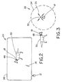
- FIG. 2 is a schematic view of an embodiment of a containment type animal training system according to the present invention.
- FIG. 3 is a schematic view of an embodiment of an avoidance type animal training system according to the present invention.
- FIG. 4 is a schematic view of an embodiment of a containment type animal training system which includes two containment areas, one outdoor and one indoor according to the present invention
- FIG. 5 is a timing diagram view of an embodiment of transmission data packets according to the present invention:
- FIG. 6 is a timing diagram view of an embodiment of transmitted signals used in the transmission data packets of FIG. 5 ;
- FIG. 7 is a table view showing possible embodiments of bit assignments for indoor and outdoor signals according to the present invention.
- FIG. 8 is a table view showing possible rate and amplitude settings for indoor and outdoor signals according to the present invention.
- FIG. 9 is a timing diagram view of an embodiment of a stimulus signal according to the present invention.
- FIG. 10 is a table view of values of the parameters of the timing diagram of FIG. 9 , and with different amplitude and rate settings, under different load conditions (HP probe and 10 k ⁇ );
- FIG. 11 is a perspective, exploded fragmentary view of an embodiment of programming unit of the animal training system, shown in conjunction with a receiver collar assembly according to the present invention
- FIG. 12 is a perspective fragmentary detail of the programming unit and receiver of FIG. 11 , shown with the receiver connected to the serial interface of the programming unit;
- FIG. 13 is a bottom view of the receiver of FIG. 11 , showing particularly the serial interface of the receiver, and taken along section line 13 - 13 of FIG. 11 ;
- FIG. 14 is a flowchart view of an embodiment of a method according to the present invention.
- FIG. 15 is a flowchart view of a continuation of the method of FIG. 14 .
- an animal training system 10 which generally includes at least one transmitter 12 transmitting at least one transmitted signal 14 , 16 .
- a receiver 18 is in electrical, typically wireless, communication with transmitter 14 .
- Examples of animal training system include a single containment loop system 20 ( FIG. 2 ), an avoidance type animal training system 22 ( FIG. 3 ), a multiple containment loop system 24 ( FIG. 4 ), and/or some combination thereof, or even remote training systems or bark control collars.
- Transmitter 12 can include a modulator 26 for energizing at least one antenna 28 , 29 , and a controller 30 connected to modulator 26 .
- Transmitter 12 can include other elements such as pushbutton switches, an enunciator(s), indicator lights and the like.
- Avoidance system 22 includes an avoidance type antenna 32 , which is typically different than a containment wire loop antenna, and which creates avoidance zone 34 . Avoidance system 22 can transmit an avoidance type transmitted signal 35 .
- the signal or signals 14 , 16 , 35 emitted by antenna(s) 28 , 29 , 32 can include use on/off keying with 7.5 kHz and 10.7 kHz carrier frequencies, although other keying arrangements and carrier frequencies are possible.
- signal packets 36 of signals 14 , 16 , 35 can be spaced by 22 ⁇ 5 milliseconds randomly dithered. Each data bit can contain eight carrier cycles.
- a header 38 (of signals 14 , 16 , 35 ) of seventeen carrier cycles followed by eight cycles of zero is used to identify the start of an 8 bit data block 40 .
- An entire signal packet 36 takes eighty-nine carrier cycles. The total temporal length of a packet will depend on the carrier frequency.
- the present invention can include indoor type signals 42 and/or outdoor type signals 44 ( FIG. 7 ), where the difference in signal types can signal different correction levels 46 ( FIG. 8 ) in receiver 18 , for example. That is, an outdoor signal type may stimulate a higher correction level in receiver 18 as the repercussion of an animal leaving a yard may be greater (wandering into traffic, for example) than the repercussions of an animal leaving a containment area within a building, or entering an avoidance zone in a building, but staying in the building because of physical barriers.
- the signal radiated by avoidance antenna 32 may be an indoor type signal, as may be the signal radiated by second containment wire loop 29 in FIG. 4 , although this is not necessarily the case, and either indoor or outdoor signal types are possible.
- the indoor or outdoor signals 42 , 44 can be digital signals or words created using on/off keying by transmitter 14 , and having coded therewithin signal type, and/or other attributes, for example.
- Receiver 18 can be connected to collar 48 which is worn by an animal 50 , for example, although other configurations are possible.
- Receiver 18 can include a receiver antenna 52 to receive a transmitted signal 14 , 16 (from transmitter 14 through antenna(s) 28 , 29 , 32 ), where antenna 52 is connected to a demodulator 54 which is connected to a receiver controller 56 .
- Controller 56 receives at least one transmitted signal 14 , 16 , 35 , and outputs at least one correction signal 58 , which includes amplitude information and rate information as shown in FIG. 8 . If dog 50 approaches too closely to the geographical area defined by containment wire loop antenna 28 , this can be considered a first event wherein transmitted signal 14 triggers a first correction signal. Similarly, if dog 50 approaches too closely to the geographical area defined by avoidance zone 34 , this can be considered a second event wherein transmitted signal 35 triggers a second correction signal different from the first correction signal.
- a stimulation unit 60 is connected to controller 56 .
- Stimulation unit 60 receives at least one correction signal 58 and provides at least one stimulus 62 , as shown particularly in FIGS. 9 and 10 , having a predetermined quantity of energy pulses corresponding to the rate information, and where each pulse has a predetermined stimulus pulse width corresponding to the amplitude information.
- Stimulation unit 60 can include an electrical stimulus switch which is connected to controller 56 , and which electrical stimulus switch in turn energizes the primary winding of a transformer, which is connected to a voltage source, to thereby energizes the secondary winding of the same transformer which are connected to electrodes 64 which are in contact with the animal's neck and connected to the secondary wind.
- Stimulation unit 60 can further include a tone switch which is connected to and activates an enunciator; and/or a vibration switch which is connected to and activates a vibrational element.
- a tone switch which is connected to and activates an enunciator
- a vibration switch which is connected to and activates a vibrational element.
- An example of rate information is shown at 66 in FIGS. 8 and 10
- amplitude information is shown at 68 in FIGS. 8 and 10
- the quantity of energy pulses is shown at 70 in FIG. 10
- the stimulus pulse width is shown at 72 in FIG. 10 .
- amplitude settings there can be six amplitude settings (one being 0 for tone-only), and five rate settings, although different amplitude and rate settings are possible.
- a rate setting of 2 corresponds to three pulses whereas a rate setting of 5 corresponds to ten pulses (see FIG. 10 ).
- Receiver 18 can be programmed so that there is a separate set of settings for the correction delivered when indoor signal 42 is decoded.
- the amplitude setting defines the pulse width of the shock, while the rate setting defines the rate administered during the beep period, and the corresponding number of pulses. Stimulation pulses can occur while the piezo (speaker or enunciator) is oscillating (to produce a beep).
- Stimulation pulses can be evenly spaced ( ⁇ ⁇ 20%) throughout the duration of the beep.
- Examples of stimulation profiles when receiver 18 is powered by a 3.0 V power supply with the two specified load conditions (HP probe and 10 k ⁇ ) are shown in FIG. 10 ; however, the electrical load presented to electrodes 64 by the skin/fur of animal 50 is highly variable and dependent on such factors as breed, humidity, skin dryness, etc. Further, the skin/fur's electrical impedance can also be a function of the stimulus voltage as a relatively high energy pulse voltage can cause ionizing effects at the electrode's contact area, which breaks down the skin/fur's electrical impedance. Consequently, the stimulation profiles shown in FIG. 10 can be modified by the actual load conditions provided by a particular animal's skin/coat; however, the data using the 10 k ⁇ load is at least somewhat representative of actual conditions.
- Transmitted signals 14 , 16 , 35 can be outdoor type signal 44 , indoor type signal 42 and/or some combination thereof, and receiver 18 can provide correspondingly different stimuli depending on the rate and amplitude selected from FIG. 8 , for example, for the respective signal type. Consequently a first stimulus can be different than a second stimulus by a quantity of energy pulses and/or a stimulus pulse width, which allows a selectable different level of correction outputted by receiver 18 , as required by the trainer, training system and/or training conditions. Further, receiver 18 can be programmed to respond to multiple transmitters, as may be the case when receiver 18 is used with both containment loop systems 20 or 24 , and/or avoidance system 22 .
- Receiver 18 can further include a communication interface 74 , 76 connected to controller 56 , where communication interface 74 , 76 is used for programming controller 56 to provide a respective correction signal 58 corresponding to a respective transmitted signal.
- Receiver 18 can further include a + terminal at 78 for connection to the positive terminal of a battery, where terminal 76 doubles as a ⁇ terminal for connection to the negative terminal of a battery.
- Communication interface 74 , 46 can be a serial interface (two terminal).
- Animal training system 10 can include a programming unit 80 ( FIGS. 11 and 12 ) for configuring amplitude information 68 and rate information 66 for a respective correction signal 58 , within receiver 18 .
- Programming unit 80 can include user interface 82 with pushbuttons 84 and display 86 connected to a programming unit controller (not shown).
- the programming unit controller is connected to post 88 , which has post terminals 90 , 92 and 94 corresponding to receiver terminals 74 , 76 and 78 , respectively.
- receiver 18 To connect receiver 18 to programming unit 80 , receiver 18 must be disassembled from collar assembly 96 including collar 48 , retaining strip 98 and electrodes 64 . Additionally, battery 100 is removed from receiver 18 thereby exposing receiver terminals 74 , 76 , 78 for connection to programming unit 80 post terminals 90 , 92 , 94 . Retaining clip 102 holds receiver 18 to programming unit 80 during programming of receiver 18 .
- a method of configuring correction levels 46 in a receiver 18 for an animal training system 10 , 20 , 22 , 24 which includes the steps of: removing battery 100 from receiver 18 (S 100 ), connecting receiver 18 to programming unit 80 (S 102 ); selecting a configuration mode (S 104 ) using user interface 82 ; selecting one of frequency setting mode, delay setting mode or correction level mode (S 106 ); if frequency setting mode is selected then the transmitted frequencies for indoor and/or outdoor type signals can be set in steps S 108 , S 110 and S 112 ; if delay setting mode is selected then delay can be set in step S 114 ; if correction level mode is selected then one of a indoor or outdoor signal is selected corresponding to a respective indoor or outdoor correction level (S 116 ); choosing an amplitude setting for a corresponding correction level (S 118 and S 120 ); and selecting a rate setting for a corresponding correction level (S 122 and S 124 ). In step 126 , a determination is made if the correction level settings are complete;
Abstract
Description
Claims (10)
Priority Applications (7)
| Application Number | Priority Date | Filing Date | Title |
|---|---|---|---|
| US11/442,837 US7779788B2 (en) | 2006-05-30 | 2006-05-30 | Animal training system with multiple configurable correction settings |
| ES07010466.6T ES2602268T3 (en) | 2006-05-30 | 2007-05-25 | Animal training system with multiple configurable correction settings |
| EP07010466.6A EP1862067B1 (en) | 2006-05-30 | 2007-05-25 | Animal training system with multiple configurable correction settings |
| DK07010466.6T DK1862067T3 (en) | 2006-05-30 | 2007-05-25 | Animal training system with several configurable correction settings |
| CA2590483A CA2590483C (en) | 2006-05-30 | 2007-05-29 | Animal training system with multiple configurable correction settings |
| AU2007202432A AU2007202432B2 (en) | 2006-05-30 | 2007-05-29 | Animal training system with multiple configurable correction settings |
| CN200710146486XA CN101103703B (en) | 2006-05-30 | 2007-05-30 | Animal training system with multiple configurable correction settings |
Applications Claiming Priority (1)
| Application Number | Priority Date | Filing Date | Title |
|---|---|---|---|
| US11/442,837 US7779788B2 (en) | 2006-05-30 | 2006-05-30 | Animal training system with multiple configurable correction settings |
Publications (2)
| Publication Number | Publication Date |
|---|---|
| US20070277749A1 US20070277749A1 (en) | 2007-12-06 |
| US7779788B2 true US7779788B2 (en) | 2010-08-24 |
Family
ID=38577594
Family Applications (1)
| Application Number | Title | Priority Date | Filing Date |
|---|---|---|---|
| US11/442,837 Active 2029-04-26 US7779788B2 (en) | 2006-05-30 | 2006-05-30 | Animal training system with multiple configurable correction settings |
Country Status (7)
| Country | Link |
|---|---|
| US (1) | US7779788B2 (en) |
| EP (1) | EP1862067B1 (en) |
| CN (1) | CN101103703B (en) |
| AU (1) | AU2007202432B2 (en) |
| CA (1) | CA2590483C (en) |
| DK (1) | DK1862067T3 (en) |
| ES (1) | ES2602268T3 (en) |
Cited By (19)
| Publication number | Priority date | Publication date | Assignee | Title |
|---|---|---|---|---|
| US7826804B1 (en) * | 2006-11-17 | 2010-11-02 | Patrick Wright | Wireless animal calling system and associated method |
| US20120000431A1 (en) * | 2010-07-05 | 2012-01-05 | Kamran Khoshkish | Electronic Pet Containment System |
| US20160100552A1 (en) * | 2014-10-14 | 2016-04-14 | E-Collar Technologies, Inc. | Reconfigurable animal traning apparatus and system |
| US9516863B2 (en) | 2013-12-03 | 2016-12-13 | Radio Systems Corporation | Threshold barrier system |
| US9703964B2 (en) | 2013-12-03 | 2017-07-11 | Radio Systems Corporation | Method and apparatus for verifying battery authenticity |
| US10231440B2 (en) | 2015-06-16 | 2019-03-19 | Radio Systems Corporation | RF beacon proximity determination enhancement |
| US10514439B2 (en) | 2017-12-15 | 2019-12-24 | Radio Systems Corporation | Location based wireless pet containment system using single base unit |
| US10613559B2 (en) | 2016-07-14 | 2020-04-07 | Radio Systems Corporation | Apparatus, systems and methods for generating voltage excitation waveforms |
| US10645908B2 (en) | 2015-06-16 | 2020-05-12 | Radio Systems Corporation | Systems and methods for providing a sound masking environment |
| US10674709B2 (en) | 2011-12-05 | 2020-06-09 | Radio Systems Corporation | Piezoelectric detection coupling of a bark collar |
| US10842128B2 (en) | 2017-12-12 | 2020-11-24 | Radio Systems Corporation | Method and apparatus for applying, monitoring, and adjusting a stimulus to a pet |
| US10986813B2 (en) | 2017-12-12 | 2021-04-27 | Radio Systems Corporation | Method and apparatus for applying, monitoring, and adjusting a stimulus to a pet |
| US11109182B2 (en) | 2017-02-27 | 2021-08-31 | Radio Systems Corporation | Threshold barrier system |
| US11238889B2 (en) | 2019-07-25 | 2022-02-01 | Radio Systems Corporation | Systems and methods for remote multi-directional bark deterrence |
| US11372077B2 (en) | 2017-12-15 | 2022-06-28 | Radio Systems Corporation | Location based wireless pet containment system using single base unit |
| US11394196B2 (en) | 2017-11-10 | 2022-07-19 | Radio Systems Corporation | Interactive application to protect pet containment systems from external surge damage |
| US11470814B2 (en) | 2011-12-05 | 2022-10-18 | Radio Systems Corporation | Piezoelectric detection coupling of a bark collar |
| US11490597B2 (en) | 2020-07-04 | 2022-11-08 | Radio Systems Corporation | Systems, methods, and apparatus for establishing keep out zones within wireless containment regions |
| US11553692B2 (en) | 2011-12-05 | 2023-01-17 | Radio Systems Corporation | Piezoelectric detection coupling of a bark collar |
Families Citing this family (8)
| Publication number | Priority date | Publication date | Assignee | Title |
|---|---|---|---|---|
| CN101554142B (en) * | 2009-05-18 | 2011-11-23 | 中国人民解放军国防科学技术大学 | Animal intelligence training system |
| CN101755688B (en) * | 2009-10-24 | 2011-09-21 | 宁波市鄞州云帆工程咨询有限公司 | Voice reminding type feeder |
| US20110221597A1 (en) * | 2010-03-11 | 2011-09-15 | Jameson James L | Animal Training Device Having a Programmable Stimulus Delivery Switch |
| CN102160527B (en) * | 2011-03-07 | 2012-11-28 | 沈阳医学院 | Intelligent wireless remote control simulation device used for animal memory training system |
| CN105191818B (en) * | 2015-10-15 | 2017-10-27 | 成都九十度工业产品设计有限公司 | The automatic control system and method for calling trainer back of a kind of pet dog |
| CN106688897A (en) * | 2017-01-19 | 2017-05-24 | 福建省农业科学院畜牧兽医研究所 | Annular ecological cycle sheep cot system under forest in hilly and mountain area and using method thereof |
| CN109106361A (en) * | 2017-06-23 | 2019-01-01 | 周厚荣 | A kind of monitoring device inducing animal ventricular fibrillation |
| CN112167090B (en) * | 2020-11-11 | 2023-05-02 | 四川省建研全固建筑新技术工程有限公司 | Animal behavior training and displaying system and method |
Citations (13)
| Publication number | Priority date | Publication date | Assignee | Title |
|---|---|---|---|---|
| US5606936A (en) * | 1995-04-25 | 1997-03-04 | Davis; James E. | Animal restraining system |
| US5787841A (en) | 1996-10-29 | 1998-08-04 | Joint Techno Concepts International, Inc. | Apparatus and method for electronic exclusion and confinement of animals relative to a selected area |
| US5844489A (en) | 1994-08-05 | 1998-12-01 | Yarnall, Jr.; Robert G. | Electronic confinement system for animals or people transmitting digitally encoded signals |
| US6151276A (en) | 1997-12-19 | 2000-11-21 | Ifco Enterprises, Inc. | Echo-ranging electronic boundary system |
| US6166643A (en) * | 1997-10-23 | 2000-12-26 | Janning; Joseph J. | Method and apparatus for controlling the whereabouts of an animal |
| US6170439B1 (en) * | 1999-06-24 | 2001-01-09 | Tri-Tronics, Inc. | Remote controlled animal training system |
| US6191693B1 (en) | 2000-03-07 | 2001-02-20 | Radio Systems Corporation | Electronic animal deterrent for protecting an area |
| US20010035134A1 (en) | 1999-03-24 | 2001-11-01 | Norval Stapelfeld | Animal control system |
| US20010042522A1 (en) | 1996-10-29 | 2001-11-22 | Joint Techno Concepts International, Inc. | Apparatus and method for electronic exclusion and confinement of animals relative ro a selected area |
| US6360698B1 (en) * | 1999-03-24 | 2002-03-26 | Dogwatch Inc. | Animal control system |
| US6433671B1 (en) * | 1996-11-29 | 2002-08-13 | X-Cyte, Inc. | Dual mode transmitter-receiver and decoder for RF transponder tags |
| US20030034887A1 (en) | 2001-03-12 | 2003-02-20 | Crabtree Timothy L. | Article locator system |
| US6657544B2 (en) | 1996-10-29 | 2003-12-02 | Joint Techno Concepts International, Inc. | Apparatus and method for electronic exclusion and confinement of animals relative to a selected area |
Family Cites Families (4)
| Publication number | Priority date | Publication date | Assignee | Title |
|---|---|---|---|---|
| US5913284A (en) * | 1996-02-27 | 1999-06-22 | Innotek, Inc. | Stimulation device and technique |
| US6079367A (en) * | 1997-10-10 | 2000-06-27 | Dogwatch, Inc. | Animal training apparatus and method |
| US6575120B1 (en) * | 2000-09-11 | 2003-06-10 | Dogwatch Inc. | Animal control system |
| CN2759161Y (en) * | 2004-12-24 | 2006-02-22 | 张卫忠 | Pets training device |
-
2006
- 2006-05-30 US US11/442,837 patent/US7779788B2/en active Active
-
2007
- 2007-05-25 ES ES07010466.6T patent/ES2602268T3/en active Active
- 2007-05-25 DK DK07010466.6T patent/DK1862067T3/en active
- 2007-05-25 EP EP07010466.6A patent/EP1862067B1/en active Active
- 2007-05-29 AU AU2007202432A patent/AU2007202432B2/en active Active
- 2007-05-29 CA CA2590483A patent/CA2590483C/en active Active
- 2007-05-30 CN CN200710146486XA patent/CN101103703B/en active Active
Patent Citations (16)
| Publication number | Priority date | Publication date | Assignee | Title |
|---|---|---|---|---|
| US5844489A (en) | 1994-08-05 | 1998-12-01 | Yarnall, Jr.; Robert G. | Electronic confinement system for animals or people transmitting digitally encoded signals |
| US5606936A (en) * | 1995-04-25 | 1997-03-04 | Davis; James E. | Animal restraining system |
| US20010042522A1 (en) | 1996-10-29 | 2001-11-22 | Joint Techno Concepts International, Inc. | Apparatus and method for electronic exclusion and confinement of animals relative ro a selected area |
| US5787841A (en) | 1996-10-29 | 1998-08-04 | Joint Techno Concepts International, Inc. | Apparatus and method for electronic exclusion and confinement of animals relative to a selected area |
| US6657544B2 (en) | 1996-10-29 | 2003-12-02 | Joint Techno Concepts International, Inc. | Apparatus and method for electronic exclusion and confinement of animals relative to a selected area |
| US6600422B2 (en) | 1996-10-29 | 2003-07-29 | Joint Techno Concepts International, Inc. | Apparatus and method for electronic exclusion and confinement of animals relative to a selected area |
| US6433671B1 (en) * | 1996-11-29 | 2002-08-13 | X-Cyte, Inc. | Dual mode transmitter-receiver and decoder for RF transponder tags |
| US6166643A (en) * | 1997-10-23 | 2000-12-26 | Janning; Joseph J. | Method and apparatus for controlling the whereabouts of an animal |
| US6151276A (en) | 1997-12-19 | 2000-11-21 | Ifco Enterprises, Inc. | Echo-ranging electronic boundary system |
| US20010035134A1 (en) | 1999-03-24 | 2001-11-01 | Norval Stapelfeld | Animal control system |
| US6360698B1 (en) * | 1999-03-24 | 2002-03-26 | Dogwatch Inc. | Animal control system |
| US6467435B2 (en) * | 1999-03-24 | 2002-10-22 | Dogwatch Inc. | Animal control system |
| US6170439B1 (en) * | 1999-06-24 | 2001-01-09 | Tri-Tronics, Inc. | Remote controlled animal training system |
| US6191693B1 (en) | 2000-03-07 | 2001-02-20 | Radio Systems Corporation | Electronic animal deterrent for protecting an area |
| US20030034887A1 (en) | 2001-03-12 | 2003-02-20 | Crabtree Timothy L. | Article locator system |
| US6788199B2 (en) | 2001-03-12 | 2004-09-07 | Eureka Technology Partners, Llc | Article locator system |
Cited By (21)
| Publication number | Priority date | Publication date | Assignee | Title |
|---|---|---|---|---|
| US7826804B1 (en) * | 2006-11-17 | 2010-11-02 | Patrick Wright | Wireless animal calling system and associated method |
| US20120000431A1 (en) * | 2010-07-05 | 2012-01-05 | Kamran Khoshkish | Electronic Pet Containment System |
| US11553692B2 (en) | 2011-12-05 | 2023-01-17 | Radio Systems Corporation | Piezoelectric detection coupling of a bark collar |
| US11470814B2 (en) | 2011-12-05 | 2022-10-18 | Radio Systems Corporation | Piezoelectric detection coupling of a bark collar |
| US10674709B2 (en) | 2011-12-05 | 2020-06-09 | Radio Systems Corporation | Piezoelectric detection coupling of a bark collar |
| US9516863B2 (en) | 2013-12-03 | 2016-12-13 | Radio Systems Corporation | Threshold barrier system |
| US9703964B2 (en) | 2013-12-03 | 2017-07-11 | Radio Systems Corporation | Method and apparatus for verifying battery authenticity |
| US10653114B2 (en) * | 2014-10-14 | 2020-05-19 | E-Collar Technologies, Inc. | Reconfigurable animal traning apparatus and system |
| US20160100552A1 (en) * | 2014-10-14 | 2016-04-14 | E-Collar Technologies, Inc. | Reconfigurable animal traning apparatus and system |
| US10231440B2 (en) | 2015-06-16 | 2019-03-19 | Radio Systems Corporation | RF beacon proximity determination enhancement |
| US10645908B2 (en) | 2015-06-16 | 2020-05-12 | Radio Systems Corporation | Systems and methods for providing a sound masking environment |
| US10613559B2 (en) | 2016-07-14 | 2020-04-07 | Radio Systems Corporation | Apparatus, systems and methods for generating voltage excitation waveforms |
| US11109182B2 (en) | 2017-02-27 | 2021-08-31 | Radio Systems Corporation | Threshold barrier system |
| US11394196B2 (en) | 2017-11-10 | 2022-07-19 | Radio Systems Corporation | Interactive application to protect pet containment systems from external surge damage |
| US10842128B2 (en) | 2017-12-12 | 2020-11-24 | Radio Systems Corporation | Method and apparatus for applying, monitoring, and adjusting a stimulus to a pet |
| US10986813B2 (en) | 2017-12-12 | 2021-04-27 | Radio Systems Corporation | Method and apparatus for applying, monitoring, and adjusting a stimulus to a pet |
| US10955521B2 (en) | 2017-12-15 | 2021-03-23 | Radio Systems Corporation | Location based wireless pet containment system using single base unit |
| US11372077B2 (en) | 2017-12-15 | 2022-06-28 | Radio Systems Corporation | Location based wireless pet containment system using single base unit |
| US10514439B2 (en) | 2017-12-15 | 2019-12-24 | Radio Systems Corporation | Location based wireless pet containment system using single base unit |
| US11238889B2 (en) | 2019-07-25 | 2022-02-01 | Radio Systems Corporation | Systems and methods for remote multi-directional bark deterrence |
| US11490597B2 (en) | 2020-07-04 | 2022-11-08 | Radio Systems Corporation | Systems, methods, and apparatus for establishing keep out zones within wireless containment regions |
Also Published As
| Publication number | Publication date |
|---|---|
| AU2007202432A1 (en) | 2007-12-20 |
| ES2602268T3 (en) | 2017-02-20 |
| EP1862067A2 (en) | 2007-12-05 |
| CN101103703B (en) | 2010-06-02 |
| US20070277749A1 (en) | 2007-12-06 |
| CA2590483C (en) | 2010-10-19 |
| CA2590483A1 (en) | 2007-11-30 |
| EP1862067A3 (en) | 2007-12-12 |
| CN101103703A (en) | 2008-01-16 |
| AU2007202432B2 (en) | 2010-03-11 |
| DK1862067T3 (en) | 2016-10-24 |
| EP1862067B1 (en) | 2016-08-10 |
Similar Documents
| Publication | Publication Date | Title |
|---|---|---|
| US7779788B2 (en) | Animal training system with multiple configurable correction settings | |
| US5815077A (en) | Electronic collar for locating and training animals | |
| US8342135B2 (en) | Method and apparatus for varying animal correction signals | |
| US5353744A (en) | Animal control apparatus | |
| US20050217606A1 (en) | Intensity variation device for training animals | |
| US6079367A (en) | Animal training apparatus and method | |
| US5351653A (en) | Animal training method using positive and negative audio stimuli | |
| US5911199A (en) | Pressure sensitive animal training device | |
| US7819087B2 (en) | Remote controlled animal training system with wireless communication system | |
| US5559498A (en) | Combination confinement and remote training system | |
| US7017524B2 (en) | Intensity variation device for training animals | |
| US7565885B2 (en) | Control of animal containment system transmitter settings with minimal switches | |
| US7937042B2 (en) | Animal training and tracking system using RF identification tags | |
| US6058889A (en) | Combination confinement system and bark inhibitor | |
| AU746263B2 (en) | An echo-ranging electronic boundary system | |
| US5868103A (en) | Method and apparatus for controlling an animal | |
| US7204204B1 (en) | Method for creating an avoidance zone | |
| US20090013939A1 (en) | Apparatus and method for restricting movement of an animal into or out of a defined area | |
| US7046152B1 (en) | Method and apparatus for communicating control signals | |
| US20220394955A1 (en) | Remote animal training system | |
| US20210185984A1 (en) | Systems and methods of monitoring and training dogs and determining the distance between a dog and a person | |
| US7068174B1 (en) | Method and apparatus for communicating an animal control signal | |
| US20230146762A1 (en) | Electronic training collar and base system | |
| KR101712383B1 (en) | Animal training apparatus by using compliment message |
Legal Events
| Date | Code | Title | Description |
|---|---|---|---|
| AS | Assignment |
Owner name: INNOTEK, INC., INDIANA Free format text: ASSIGNMENT OF ASSIGNORS INTEREST;ASSIGNOR:MOORE, WILLIAM P.;REEL/FRAME:017991/0131 Effective date: 20060602 |
|
| AS | Assignment |
Owner name: FIFTH THIRD BANK, AS ADMINISTRATIVE AGENT, OHIO Free format text: SECURITY INTEREST;ASSIGNOR:INNOTEK, INC.;REEL/FRAME:018291/0913 Effective date: 20060915 Owner name: FIFTH THIRD BANK, AS ADMINISTRATIVE AGENT,OHIO Free format text: SECURITY INTEREST;ASSIGNOR:INNOTEK, INC.;REEL/FRAME:018291/0913 Effective date: 20060915 |
|
| STCF | Information on status: patent grant |
Free format text: PATENTED CASE |
|
| FEPP | Fee payment procedure |
Free format text: PAT HOLDER NO LONGER CLAIMS SMALL ENTITY STATUS, ENTITY STATUS SET TO UNDISCOUNTED (ORIGINAL EVENT CODE: STOL); ENTITY STATUS OF PATENT OWNER: LARGE ENTITY |
|
| AS | Assignment |
Owner name: THE BANK OF NEW YORK MELLON TRUST COMPANY, N.A., F Free format text: SECURITY AGREEMENT;ASSIGNORS:RADIO SYSTEMS CORPORATION;INNOTEK, INC.;INVISIBLE FENCE, INC.;REEL/FRAME:029308/0434 Effective date: 20121023 Owner name: THE BANK OF NEW YORK MELLON TRUST COMPANY, N.A., F Free format text: SECURITY AGREEMENT;ASSIGNORS:RADIO SYSTEMS CORPORATION;INNOTEK, INC.;INVISIBLE FENCE, INC.;REEL/FRAME:029308/0001 Effective date: 20121023 |
|
| FPAY | Fee payment |
Year of fee payment: 4 |
|
| AS | Assignment |
Owner name: THE BANK OF NEW YORK MELLON TRUST COMPANY, N.A., F Free format text: CORRECTIVE ASSIGNMENT TO CORRECT THE ASSIGNMENT DOCUMENT WHICH INCORRECTLY IDENTIFIED PATENT APP. NO. 13/302,477 PREVIOUSLY RECORDED ON REEL 029308 FRAME 0001. ASSIGNOR(S) HEREBY CONFIRMS THE SECURITY INTEREST;ASSIGNORS:RADIO SYSTEMS CORPORATION;INVISIBLE FENCE, INC.;INNOTEK, INC.;REEL/FRAME:037127/0491 Effective date: 20150929 |
|
| AS | Assignment |
Owner name: THE BANK OF NEW YORK MELLON TRUST COMPANY, N.A., F Free format text: CORRECTIVE ASSIGNMENT TO CORRECT THE INCORRECT PATENT NO. 7814565 PREVIOUSLY RECORDED AT REEL: 029308 FRAME: 0001. ASSIGNOR(S) HEREBY CONFIRMS THE SECURITY AGREEMENT;ASSIGNORS:RADIO SYSTEMS CORPORATION;INNOTEK, INC.;INVISIBLE FENCE, INC.;REEL/FRAME:038332/0343 Effective date: 20121023 |
|
| AS | Assignment |
Owner name: THE BANK OF NEW YORK MELLON TRUST COMPANY, N.A., F Free format text: CORRECTIVE ASSIGNMENT TO CORRECT THE INCORRECT PATENT NO. 7814565 PREVIOUSLY RECORDED AT REEL: 037127 FRAME: 0491. ASSIGNOR(S) HEREBY CONFIRMS THE SECURITY INTEREST;ASSIGNORS:RADIO SYSTEMS CORPORATION;INVISIBLE FENCE, INC.;INNOTEK, INC.;REEL/FRAME:038601/0757 Effective date: 20150929 |
|
| AS | Assignment |
Owner name: FIFTH THIRD BANK, AS ADMINISTRATIVE AGENT, ILLINOI Free format text: SECURITY AGREEMENT;ASSIGNOR:RADIO SYSTEMS CORPORATION;REEL/FRAME:042523/0729 Effective date: 20170502 Owner name: FIFTH THIRD BANK, AS ADMINISTRATIVE AGENT, ILLINOIS Free format text: SECURITY AGREEMENT;ASSIGNOR:RADIO SYSTEMS CORPORATION;REEL/FRAME:042523/0729 Effective date: 20170502 |
|
| AS | Assignment |
Owner name: INVISIBLE FENCE, INC., TENNESSEE Free format text: RELEASE BY SECURED PARTY;ASSIGNOR:THE BANK OF NEW YORK MELLON TRUST COMPANY, N.A.;REEL/FRAME:043038/0291 Effective date: 20170502 Owner name: RADIO SYSTEMS CORPORATION, TENNESSEE Free format text: RELEASE BY SECURED PARTY;ASSIGNOR:THE BANK OF NEW YORK MELLON TRUST COMPANY, N.A.;REEL/FRAME:043038/0291 Effective date: 20170502 Owner name: INNOTEK, INC., TENNESSEE Free format text: RELEASE BY SECURED PARTY;ASSIGNOR:THE BANK OF NEW YORK MELLON TRUST COMPANY, N.A.;REEL/FRAME:043038/0291 Effective date: 20170502 |
|
| MAFP | Maintenance fee payment |
Free format text: PAYMENT OF MAINTENANCE FEE, 8TH YEAR, LARGE ENTITY (ORIGINAL EVENT CODE: M1552) Year of fee payment: 8 |
|
| AS | Assignment |
Owner name: RADIO SYSTEMS CORPORATION, TENNESSEE Free format text: ASSIGNMENT OF ASSIGNORS INTEREST;ASSIGNOR:INNOTEK, INC.;REEL/FRAME:052926/0847 Effective date: 20200610 |
|
| AS | Assignment |
Owner name: FIFTH THIRD BANK, N.A., AS COLLATERAL AGENT, OHIO Free format text: SECURITY AGREEMENT;ASSIGNORS:RADIO SYSTEMS CORPORATION;INNOTEK, INC.;REEL/FRAME:053116/0599 Effective date: 20200701 Owner name: WILMINGTON TRUST, NATIONAL ASSOCIATION, MINNESOTA Free format text: NOTICE OF CONFIRMATION OF GRANT OF SECURITY INTEREST IN PATENTS;ASSIGNORS:INNOTEK, INC.;RADIO SYSTEMS CORPORATION;REEL/FRAME:053117/0189 Effective date: 20200701 |
|
| AS | Assignment |
Owner name: RADIO SYSTEMS CORPORATION, TENNESSEE Free format text: RELEASE OF SECURITY INTEREST IN PATENTS;ASSIGNOR:FIFTH THIRD BANK;REEL/FRAME:053122/0378 Effective date: 20200701 Owner name: PREMIER PET PRODUCTS, LLC, TENNESSEE Free format text: RELEASE OF SECURITY INTEREST IN PATENTS;ASSIGNOR:FIFTH THIRD BANK;REEL/FRAME:053122/0344 Effective date: 20200701 Owner name: RADIO SYSTEMS CORPORATION, TENNESSEE Free format text: RELEASE OF SECURITY INTEREST IN PATENTS;ASSIGNOR:FIFTH THIRD BANK;REEL/FRAME:053122/0268 Effective date: 20200701 Owner name: INNOTEK, INC., TENNESSEE Free format text: RELEASE OF SECURITY INTEREST IN PATENTS;ASSIGNOR:FIFTH THIRD BANK;REEL/FRAME:053122/0378 Effective date: 20200701 Owner name: INVISIBLE FENCE, INC., TENNESSEE Free format text: RELEASE OF SECURITY INTEREST IN PATENTS;ASSIGNOR:FIFTH THIRD BANK;REEL/FRAME:053122/0453 Effective date: 20200701 Owner name: PREMIER PET PRODUCTS, LLC, TENNESSEE Free format text: RELEASE OF SECURITY INTEREST IN PATENTS;ASSIGNOR:FIFTH THIRD BANK;REEL/FRAME:053122/0268 Effective date: 20200701 Owner name: INNOTEK, INC., TENNESSEE Free format text: RELEASE OF SECURITY INTEREST IN PATENTS;ASSIGNOR:FIFTH THIRD BANK;REEL/FRAME:053122/0344 Effective date: 20200701 Owner name: INNOTEK, INC., TENNESSEE Free format text: RELEASE OF SECURITY INTEREST IN PATENTS;ASSIGNOR:FIFTH THIRD BANK;REEL/FRAME:053122/0268 Effective date: 20200701 Owner name: RADIO SYSTEMS CORPORATION, TENNESSEE Free format text: RELEASE OF SECURITY INTEREST IN PATENTS;ASSIGNOR:FIFTH THIRD BANK;REEL/FRAME:053122/0344 Effective date: 20200701 Owner name: PREMIER PET PRODUCTS, LLC, TENNESSEE Free format text: RELEASE OF SECURITY INTEREST IN PATENTS;ASSIGNOR:FIFTH THIRD BANK;REEL/FRAME:053122/0378 Effective date: 20200701 Owner name: INVISIBLE FENCE, INC., TENNESSEE Free format text: RELEASE OF SECURITY INTEREST IN PATENTS;ASSIGNOR:FIFTH THIRD BANK;REEL/FRAME:053122/0344 Effective date: 20200701 Owner name: INNOTEK, INC., TENNESSEE Free format text: RELEASE OF SECURITY INTEREST IN PATENTS;ASSIGNOR:FIFTH THIRD BANK;REEL/FRAME:053122/0453 Effective date: 20200701 Owner name: RADIO SYSTEMS CORPORATION, TENNESSEE Free format text: RELEASE OF SECURITY INTEREST IN PATENTS;ASSIGNOR:FIFTH THIRD BANK;REEL/FRAME:053122/0453 Effective date: 20200701 Owner name: INVISIBLE FENCE, INC., TENNESSEE Free format text: RELEASE OF SECURITY INTEREST IN PATENTS;ASSIGNOR:FIFTH THIRD BANK;REEL/FRAME:053122/0268 Effective date: 20200701 Owner name: PREMIER PET PRODUCTS, LLC, TENNESSEE Free format text: RELEASE OF SECURITY INTEREST IN PATENTS;ASSIGNOR:FIFTH THIRD BANK;REEL/FRAME:053122/0453 Effective date: 20200701 Owner name: INVISIBLE FENCE, INC., TENNESSEE Free format text: RELEASE OF SECURITY INTEREST IN PATENTS;ASSIGNOR:FIFTH THIRD BANK;REEL/FRAME:053122/0378 Effective date: 20200701 Owner name: INNOTEK, INC., TENNESSEE Free format text: RELEASE OF SECURITY INTEREST IN PATENTS - ABL;ASSIGNOR:FIFTH THIRD BANK;REEL/FRAME:053122/0711 Effective date: 20200701 |
|
| AS | Assignment |
Owner name: BANK OF MONTREAL, ILLINOIS Free format text: TERM LOAN NOTICE AND CONFIRMATION OF GRANT OF SECURITY INTEREST IN PATENTS;ASSIGNOR:RADIO SYSTEMS CORPORATION;REEL/FRAME:058313/0755 Effective date: 20211119 |
|
| MAFP | Maintenance fee payment |
Free format text: PAYMENT OF MAINTENANCE FEE, 12TH YEAR, LARGE ENTITY (ORIGINAL EVENT CODE: M1553); ENTITY STATUS OF PATENT OWNER: LARGE ENTITY Year of fee payment: 12 |